CN115593399A - Driving assistance device for vehicle - Google Patents
Driving assistance device for vehicle Download PDFInfo
- Publication number
- CN115593399A CN115593399A CN202210683750.8A CN202210683750A CN115593399A CN 115593399 A CN115593399 A CN 115593399A CN 202210683750 A CN202210683750 A CN 202210683750A CN 115593399 A CN115593399 A CN 115593399A
- Authority
- CN
- China
- Prior art keywords
- vehicle
- intersection
- oncoming vehicle
- path
- predicted
- Prior art date
- Legal status (The legal status is an assumption and is not a legal conclusion. Google has not performed a legal analysis and makes no representation as to the accuracy of the status listed.)
- Pending
Links
- 238000012937 correction Methods 0.000 claims description 18
- 230000004397 blinking Effects 0.000 claims description 4
- 238000012545 processing Methods 0.000 description 10
- 238000000034 method Methods 0.000 description 9
- 101100208381 Caenorhabditis elegans tth-1 gene Proteins 0.000 description 7
- 230000001133 acceleration Effects 0.000 description 6
- 239000013256 coordination polymer Substances 0.000 description 5
- 238000010586 diagram Methods 0.000 description 5
- 230000008569 process Effects 0.000 description 5
- 238000001514 detection method Methods 0.000 description 4
- 239000000470 constituent Substances 0.000 description 3
- 230000001629 suppression Effects 0.000 description 3
- 230000005540 biological transmission Effects 0.000 description 2
- 230000000694 effects Effects 0.000 description 2
- 239000000284 extract Substances 0.000 description 2
- 230000007246 mechanism Effects 0.000 description 2
- 238000012544 monitoring process Methods 0.000 description 2
- 230000003044 adaptive effect Effects 0.000 description 1
- 238000004891 communication Methods 0.000 description 1
- 238000005516 engineering process Methods 0.000 description 1
- 239000012530 fluid Substances 0.000 description 1
- 238000012986 modification Methods 0.000 description 1
- 230000004048 modification Effects 0.000 description 1
- 230000002093 peripheral effect Effects 0.000 description 1
- 230000004044 response Effects 0.000 description 1
- 239000007787 solid Substances 0.000 description 1
- 230000001360 synchronised effect Effects 0.000 description 1
Images


Classifications
-
- G—PHYSICS
- G06—COMPUTING; CALCULATING OR COUNTING
- G06V—IMAGE OR VIDEO RECOGNITION OR UNDERSTANDING
- G06V20/00—Scenes; Scene-specific elements
- G06V20/50—Context or environment of the image
- G06V20/56—Context or environment of the image exterior to a vehicle by using sensors mounted on the vehicle
-
- B—PERFORMING OPERATIONS; TRANSPORTING
- B60—VEHICLES IN GENERAL
- B60W—CONJOINT CONTROL OF VEHICLE SUB-UNITS OF DIFFERENT TYPE OR DIFFERENT FUNCTION; CONTROL SYSTEMS SPECIALLY ADAPTED FOR HYBRID VEHICLES; ROAD VEHICLE DRIVE CONTROL SYSTEMS FOR PURPOSES NOT RELATED TO THE CONTROL OF A PARTICULAR SUB-UNIT
- B60W30/00—Purposes of road vehicle drive control systems not related to the control of a particular sub-unit, e.g. of systems using conjoint control of vehicle sub-units, or advanced driver assistance systems for ensuring comfort, stability and safety or drive control systems for propelling or retarding the vehicle
- B60W30/08—Active safety systems predicting or avoiding probable or impending collision or attempting to minimise its consequences
- B60W30/09—Taking automatic action to avoid collision, e.g. braking and steering
-
- B—PERFORMING OPERATIONS; TRANSPORTING
- B60—VEHICLES IN GENERAL
- B60W—CONJOINT CONTROL OF VEHICLE SUB-UNITS OF DIFFERENT TYPE OR DIFFERENT FUNCTION; CONTROL SYSTEMS SPECIALLY ADAPTED FOR HYBRID VEHICLES; ROAD VEHICLE DRIVE CONTROL SYSTEMS FOR PURPOSES NOT RELATED TO THE CONTROL OF A PARTICULAR SUB-UNIT
- B60W10/00—Conjoint control of vehicle sub-units of different type or different function
- B60W10/18—Conjoint control of vehicle sub-units of different type or different function including control of braking systems
-
- B—PERFORMING OPERATIONS; TRANSPORTING
- B60—VEHICLES IN GENERAL
- B60W—CONJOINT CONTROL OF VEHICLE SUB-UNITS OF DIFFERENT TYPE OR DIFFERENT FUNCTION; CONTROL SYSTEMS SPECIALLY ADAPTED FOR HYBRID VEHICLES; ROAD VEHICLE DRIVE CONTROL SYSTEMS FOR PURPOSES NOT RELATED TO THE CONTROL OF A PARTICULAR SUB-UNIT
- B60W30/00—Purposes of road vehicle drive control systems not related to the control of a particular sub-unit, e.g. of systems using conjoint control of vehicle sub-units, or advanced driver assistance systems for ensuring comfort, stability and safety or drive control systems for propelling or retarding the vehicle
- B60W30/08—Active safety systems predicting or avoiding probable or impending collision or attempting to minimise its consequences
- B60W30/095—Predicting travel path or likelihood of collision
- B60W30/0953—Predicting travel path or likelihood of collision the prediction being responsive to vehicle dynamic parameters
-
- B—PERFORMING OPERATIONS; TRANSPORTING
- B60—VEHICLES IN GENERAL
- B60W—CONJOINT CONTROL OF VEHICLE SUB-UNITS OF DIFFERENT TYPE OR DIFFERENT FUNCTION; CONTROL SYSTEMS SPECIALLY ADAPTED FOR HYBRID VEHICLES; ROAD VEHICLE DRIVE CONTROL SYSTEMS FOR PURPOSES NOT RELATED TO THE CONTROL OF A PARTICULAR SUB-UNIT
- B60W30/00—Purposes of road vehicle drive control systems not related to the control of a particular sub-unit, e.g. of systems using conjoint control of vehicle sub-units, or advanced driver assistance systems for ensuring comfort, stability and safety or drive control systems for propelling or retarding the vehicle
- B60W30/08—Active safety systems predicting or avoiding probable or impending collision or attempting to minimise its consequences
- B60W30/095—Predicting travel path or likelihood of collision
- B60W30/0956—Predicting travel path or likelihood of collision the prediction being responsive to traffic or environmental parameters
-
- B—PERFORMING OPERATIONS; TRANSPORTING
- B60—VEHICLES IN GENERAL
- B60W—CONJOINT CONTROL OF VEHICLE SUB-UNITS OF DIFFERENT TYPE OR DIFFERENT FUNCTION; CONTROL SYSTEMS SPECIALLY ADAPTED FOR HYBRID VEHICLES; ROAD VEHICLE DRIVE CONTROL SYSTEMS FOR PURPOSES NOT RELATED TO THE CONTROL OF A PARTICULAR SUB-UNIT
- B60W30/00—Purposes of road vehicle drive control systems not related to the control of a particular sub-unit, e.g. of systems using conjoint control of vehicle sub-units, or advanced driver assistance systems for ensuring comfort, stability and safety or drive control systems for propelling or retarding the vehicle
- B60W30/18—Propelling the vehicle
- B60W30/18009—Propelling the vehicle related to particular drive situations
- B60W30/18109—Braking
-
- B—PERFORMING OPERATIONS; TRANSPORTING
- B60—VEHICLES IN GENERAL
- B60W—CONJOINT CONTROL OF VEHICLE SUB-UNITS OF DIFFERENT TYPE OR DIFFERENT FUNCTION; CONTROL SYSTEMS SPECIALLY ADAPTED FOR HYBRID VEHICLES; ROAD VEHICLE DRIVE CONTROL SYSTEMS FOR PURPOSES NOT RELATED TO THE CONTROL OF A PARTICULAR SUB-UNIT
- B60W30/00—Purposes of road vehicle drive control systems not related to the control of a particular sub-unit, e.g. of systems using conjoint control of vehicle sub-units, or advanced driver assistance systems for ensuring comfort, stability and safety or drive control systems for propelling or retarding the vehicle
- B60W30/18—Propelling the vehicle
- B60W30/18009—Propelling the vehicle related to particular drive situations
- B60W30/18145—Cornering
-
- B—PERFORMING OPERATIONS; TRANSPORTING
- B60—VEHICLES IN GENERAL
- B60W—CONJOINT CONTROL OF VEHICLE SUB-UNITS OF DIFFERENT TYPE OR DIFFERENT FUNCTION; CONTROL SYSTEMS SPECIALLY ADAPTED FOR HYBRID VEHICLES; ROAD VEHICLE DRIVE CONTROL SYSTEMS FOR PURPOSES NOT RELATED TO THE CONTROL OF A PARTICULAR SUB-UNIT
- B60W30/00—Purposes of road vehicle drive control systems not related to the control of a particular sub-unit, e.g. of systems using conjoint control of vehicle sub-units, or advanced driver assistance systems for ensuring comfort, stability and safety or drive control systems for propelling or retarding the vehicle
- B60W30/18—Propelling the vehicle
- B60W30/18009—Propelling the vehicle related to particular drive situations
- B60W30/18154—Approaching an intersection
-
- B—PERFORMING OPERATIONS; TRANSPORTING
- B60—VEHICLES IN GENERAL
- B60W—CONJOINT CONTROL OF VEHICLE SUB-UNITS OF DIFFERENT TYPE OR DIFFERENT FUNCTION; CONTROL SYSTEMS SPECIALLY ADAPTED FOR HYBRID VEHICLES; ROAD VEHICLE DRIVE CONTROL SYSTEMS FOR PURPOSES NOT RELATED TO THE CONTROL OF A PARTICULAR SUB-UNIT
- B60W30/00—Purposes of road vehicle drive control systems not related to the control of a particular sub-unit, e.g. of systems using conjoint control of vehicle sub-units, or advanced driver assistance systems for ensuring comfort, stability and safety or drive control systems for propelling or retarding the vehicle
- B60W30/18—Propelling the vehicle
- B60W30/18009—Propelling the vehicle related to particular drive situations
- B60W30/18159—Traversing an intersection
-
- B—PERFORMING OPERATIONS; TRANSPORTING
- B60—VEHICLES IN GENERAL
- B60W—CONJOINT CONTROL OF VEHICLE SUB-UNITS OF DIFFERENT TYPE OR DIFFERENT FUNCTION; CONTROL SYSTEMS SPECIALLY ADAPTED FOR HYBRID VEHICLES; ROAD VEHICLE DRIVE CONTROL SYSTEMS FOR PURPOSES NOT RELATED TO THE CONTROL OF A PARTICULAR SUB-UNIT
- B60W40/00—Estimation or calculation of non-directly measurable driving parameters for road vehicle drive control systems not related to the control of a particular sub unit, e.g. by using mathematical models
- B60W40/02—Estimation or calculation of non-directly measurable driving parameters for road vehicle drive control systems not related to the control of a particular sub unit, e.g. by using mathematical models related to ambient conditions
- B60W40/04—Traffic conditions
-
- G—PHYSICS
- G06—COMPUTING; CALCULATING OR COUNTING
- G06V—IMAGE OR VIDEO RECOGNITION OR UNDERSTANDING
- G06V20/00—Scenes; Scene-specific elements
- G06V20/50—Context or environment of the image
- G06V20/56—Context or environment of the image exterior to a vehicle by using sensors mounted on the vehicle
- G06V20/58—Recognition of moving objects or obstacles, e.g. vehicles or pedestrians; Recognition of traffic objects, e.g. traffic signs, traffic lights or roads
- G06V20/584—Recognition of moving objects or obstacles, e.g. vehicles or pedestrians; Recognition of traffic objects, e.g. traffic signs, traffic lights or roads of vehicle lights or traffic lights
-
- B—PERFORMING OPERATIONS; TRANSPORTING
- B60—VEHICLES IN GENERAL
- B60W—CONJOINT CONTROL OF VEHICLE SUB-UNITS OF DIFFERENT TYPE OR DIFFERENT FUNCTION; CONTROL SYSTEMS SPECIALLY ADAPTED FOR HYBRID VEHICLES; ROAD VEHICLE DRIVE CONTROL SYSTEMS FOR PURPOSES NOT RELATED TO THE CONTROL OF A PARTICULAR SUB-UNIT
- B60W2420/00—Indexing codes relating to the type of sensors based on the principle of their operation
- B60W2420/40—Photo or light sensitive means, e.g. infrared sensors
- B60W2420/403—Image sensing, e.g. optical camera
-
- B60W2420/408—
-
- B—PERFORMING OPERATIONS; TRANSPORTING
- B60—VEHICLES IN GENERAL
- B60W—CONJOINT CONTROL OF VEHICLE SUB-UNITS OF DIFFERENT TYPE OR DIFFERENT FUNCTION; CONTROL SYSTEMS SPECIALLY ADAPTED FOR HYBRID VEHICLES; ROAD VEHICLE DRIVE CONTROL SYSTEMS FOR PURPOSES NOT RELATED TO THE CONTROL OF A PARTICULAR SUB-UNIT
- B60W2420/00—Indexing codes relating to the type of sensors based on the principle of their operation
- B60W2420/54—Audio sensitive means, e.g. ultrasound
-
- B—PERFORMING OPERATIONS; TRANSPORTING
- B60—VEHICLES IN GENERAL
- B60W—CONJOINT CONTROL OF VEHICLE SUB-UNITS OF DIFFERENT TYPE OR DIFFERENT FUNCTION; CONTROL SYSTEMS SPECIALLY ADAPTED FOR HYBRID VEHICLES; ROAD VEHICLE DRIVE CONTROL SYSTEMS FOR PURPOSES NOT RELATED TO THE CONTROL OF A PARTICULAR SUB-UNIT
- B60W2552/00—Input parameters relating to infrastructure
- B60W2552/10—Number of lanes
-
- B—PERFORMING OPERATIONS; TRANSPORTING
- B60—VEHICLES IN GENERAL
- B60W—CONJOINT CONTROL OF VEHICLE SUB-UNITS OF DIFFERENT TYPE OR DIFFERENT FUNCTION; CONTROL SYSTEMS SPECIALLY ADAPTED FOR HYBRID VEHICLES; ROAD VEHICLE DRIVE CONTROL SYSTEMS FOR PURPOSES NOT RELATED TO THE CONTROL OF A PARTICULAR SUB-UNIT
- B60W2554/00—Input parameters relating to objects
- B60W2554/40—Dynamic objects, e.g. animals, windblown objects
- B60W2554/404—Characteristics
- B60W2554/4045—Intention, e.g. lane change or imminent movement
-
- B—PERFORMING OPERATIONS; TRANSPORTING
- B60—VEHICLES IN GENERAL
- B60W—CONJOINT CONTROL OF VEHICLE SUB-UNITS OF DIFFERENT TYPE OR DIFFERENT FUNCTION; CONTROL SYSTEMS SPECIALLY ADAPTED FOR HYBRID VEHICLES; ROAD VEHICLE DRIVE CONTROL SYSTEMS FOR PURPOSES NOT RELATED TO THE CONTROL OF A PARTICULAR SUB-UNIT
- B60W2554/00—Input parameters relating to objects
- B60W2554/40—Dynamic objects, e.g. animals, windblown objects
- B60W2554/404—Characteristics
- B60W2554/4046—Behavior, e.g. aggressive or erratic
-
- B—PERFORMING OPERATIONS; TRANSPORTING
- B60—VEHICLES IN GENERAL
- B60W—CONJOINT CONTROL OF VEHICLE SUB-UNITS OF DIFFERENT TYPE OR DIFFERENT FUNCTION; CONTROL SYSTEMS SPECIALLY ADAPTED FOR HYBRID VEHICLES; ROAD VEHICLE DRIVE CONTROL SYSTEMS FOR PURPOSES NOT RELATED TO THE CONTROL OF A PARTICULAR SUB-UNIT
- B60W2554/00—Input parameters relating to objects
- B60W2554/60—Traversable objects, e.g. speed bumps or curbs
-
- B—PERFORMING OPERATIONS; TRANSPORTING
- B60—VEHICLES IN GENERAL
- B60W—CONJOINT CONTROL OF VEHICLE SUB-UNITS OF DIFFERENT TYPE OR DIFFERENT FUNCTION; CONTROL SYSTEMS SPECIALLY ADAPTED FOR HYBRID VEHICLES; ROAD VEHICLE DRIVE CONTROL SYSTEMS FOR PURPOSES NOT RELATED TO THE CONTROL OF A PARTICULAR SUB-UNIT
- B60W2556/00—Input parameters relating to data
- B60W2556/40—High definition maps
Abstract
The invention provides a driving assistance device for a vehicle, which can restrain unnecessary emergency braking for an opposite vehicle from being executed in a cross road. A traveling _ ECU (14) calculates a predicted vehicle traveling path (Cm), calculates a predicted oncoming vehicle traveling path (Co) on the basis of the behavior of an oncoming vehicle (O), determines whether or not the vehicle (M) has the intention of turning right to enter a right-turn path in an intersection, corrects the predicted vehicle traveling path to a limit traveling path for the vehicle (M) to enter the right-turn path when the vehicle (M) has the intention of entering the right-turn path and cannot enter the right-turn path on the current predicted vehicle traveling path, determines whether or not the oncoming vehicle has the intention of turning right to enter the right-turn path in the intersection, and corrects the predicted oncoming vehicle traveling path (Co) to the limit traveling path for the oncoming vehicle to enter the right-turn path when the oncoming vehicle has the intention of turning right to enter the intersection and cannot enter the right-turn path on the current predicted oncoming vehicle traveling path (Co).
Description
Technical Field
The present invention relates to a driving assistance device for a vehicle capable of controlling braking of an obstacle such as a preceding vehicle and/or an oncoming vehicle.
Background
In recent years, in vehicles such as automobiles, a driving assistance device for assisting a driving operation of a driver has been put to practical use for the purpose of reducing a burden of the driving operation of the driver and improving safety. In such a driving assistance device, as the driving mode, for example, a manual driving mode in which steering and/or acceleration and deceleration are performed in accordance with an autonomous driving operation by the driver, a driving assistance mode in which steering assistance control and/or acceleration and deceleration control are performed on the premise of the autonomous driving operation by the driver, a driving assistance mode (so-called automatic driving mode) in which the vehicle travels without requiring a driving operation by the driver, and the like are set.
The driving assistance Control in each driving assistance mode is basically realized by providing an following vehicle distance Control (ACC) function and an Active Lane Keep center Control (ALKC) function. In addition, by such driving assistance control, the vehicle can be automatically driven along the driving lane while keeping the inter-vehicle distance from the preceding vehicle.
Further, as technologies relating to active safety of the driving assistance device, there are practically used: when an obstacle requiring an Emergency stop, such as a preceding vehicle or a stopped vehicle, is recognized ahead of the host vehicle, emergency Braking (AEB (collision loss reducing Braking) control is performed on the obstacle as interrupt control, and deceleration is performed until the relative speed between the host vehicle and the obstacle becomes zero. The subject of this emergency braking is not only a preceding vehicle and/or a stopped vehicle traveling ahead of the own vehicle traveling road but also an oncoming vehicle having a high risk of colliding with the own vehicle in an intersection.
For example, patent document 1 discloses the following technique: the travel risk of the vehicle is determined by predicting a travel trajectory (calculating a predicted travel path) of the vehicle when the vehicle travels at the intersection based on speed information related to the moving speed of the vehicle and intersection information including the shape of the intersection, and determining a determination position where the predicted trajectory intersects with the oncoming lane. Further, patent document 1 discloses the following technique: when it is determined that there is a risk of traveling, the vehicle is automatically braked and stopped in addition to the alarm output.
Documents of the prior art
Patent literature
Patent document 1: japanese patent laid-open publication No. 2019-32712
Disclosure of Invention
Technical problem
However, when the determination result of the travel risk started in the above-described patent document 1 is applied to the emergency braking control, for example, in a case where the oncoming vehicle does not start turning right until it reaches a position very close to the host vehicle turning right in the intersection, there is a possibility that unnecessary emergency braking is executed.
That is, the time when the host vehicle and the oncoming vehicle start turning right within the intersection is greatly different depending on the individual driver, and the turning may not be started until the road near the right turning destination depending on the driver. Therefore, even when both the host vehicle and the oncoming vehicle turn right, there is a possibility that the oncoming vehicle is determined to be a straight-ahead vehicle and emergency braking is performed, depending on the timing at which the predicted travel path in the right-turn direction of the oncoming vehicle is calculated.
The present invention has been made in view of the above circumstances, and an object thereof is to provide a driving assistance device for a vehicle capable of suppressing unnecessary sudden braking of an oncoming vehicle from being performed in an intersection.
Technical scheme
A driving assistance device for a vehicle according to an aspect of the present invention includes: a running environment recognition unit that recognizes running environment information outside the vehicle; a vehicle predicted travel path calculation unit that calculates a vehicle predicted travel path based on a driving state of a vehicle; a oncoming vehicle predicted travel path calculation unit that calculates a oncoming vehicle predicted travel path based on a behavior of the oncoming vehicle when the oncoming vehicle is detected based on the travel environment information; a vehicle turning intention determining means for determining whether or not the vehicle has an intention to enter a first intersection of the target crossing the opposite lane by turning in the intersection; a vehicle predicted path correcting unit that corrects the vehicle predicted path to a vehicle limit path that is a limit path for allowing the vehicle to enter the first intersection when the vehicle has an intention to enter the first intersection and the vehicle cannot enter the first intersection on the current vehicle predicted path; a turning intention determining unit for determining whether or not the oncoming vehicle has an intention to enter a second intersection crossing the target of the own vehicle traveling lane through a turn in the intersection; a oncoming vehicle predicted travel path correction unit that corrects the oncoming vehicle predicted travel path to an oncoming vehicle limit travel path that is a limit travel path for the oncoming vehicle to reach the second intersection, when the oncoming vehicle has an intention to enter the second intersection and cannot enter the second intersection on the current oncoming vehicle predicted travel path; and a control target setting unit that sets the oncoming vehicle as a control target for emergency braking when the predicted travel route of the subject vehicle and the predicted travel route of the oncoming vehicle overlap at least partially up to a predetermined time.
Effects of the invention
According to the driving assistance device for a vehicle of the present invention, unnecessary emergency braking for the oncoming vehicle can be suppressed from being performed within the intersection.
Drawings
Fig. 1 is an overall configuration diagram of a driving assistance device.
Fig. 2 is an explanatory view showing a monitoring area of a stereo camera, a radar, and a sonar.
Fig. 3 is a flowchart showing an emergency braking control routine.
Fig. 4 is a flowchart showing a correction processing subroutine of the predicted travel route.
Fig. 5 is an explanatory diagram illustrating a predicted travel route of the host vehicle and a predicted travel route of a preceding vehicle.
Fig. 6 is an explanatory view illustrating the predicted path of travel of the host vehicle and the predicted path of travel of the oncoming vehicle at the intersection when both the host vehicle and the oncoming vehicle start sufficient right-turn operation.
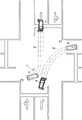
Fig. 7 is an explanatory view illustrating the predicted path of travel of the host vehicle and the predicted path of travel of the oncoming vehicle in the intersection when the host vehicle does not start a sufficient right-turn operation and the oncoming vehicle starts a sufficient right-turn operation.
Fig. 8 is an explanatory diagram showing the predicted travel path of the host vehicle and the predicted travel path of the oncoming vehicle of fig. 7 after the correction processing.
Fig. 9 is an explanatory view illustrating the predicted path of travel of the host vehicle and the predicted path of travel of the oncoming vehicle within the intersection when the host vehicle has started a sufficient turning operation and the oncoming vehicle has not started a sufficient turning operation.
Fig. 10 is an explanatory diagram showing the predicted travel path of the own vehicle and the predicted travel path of the oncoming vehicle of fig. 9 after the correction processing.
Fig. 11 is an explanatory view illustrating the predicted path of travel of the host vehicle and the predicted path of travel of the oncoming vehicle in the intersection when the host vehicle does not start a sufficient right-turn operation and the oncoming vehicle is traveling straight ahead.
Fig. 12 is an explanatory view showing the predicted travel path of the host vehicle and the predicted travel path of the oncoming vehicle in fig. 11 after the correction processing.
Description of the symbols
1 \ 8230and driving auxiliary device
10 \ 8230and camera unit
11 \ 8230and stereo camera
11a 8230and main camera
11b 8230and auxiliary camera
13 \ 8230and image recognition _ ECU
14 \ 8230and driving _ ECU
21…CP_ECU
22…E/G_ECU
23…T/M_ECU
24…BK_ECU
25…PS_ECU
31…HMI
32' 8230a throttle valve actuator
33 \ 8230and hydraulic control loop
34 \ 8230and brake actuator
35-8230and electric power steering motor
36 \ 8230and positioning unit
36a \8230andGNSS sensor
36b 8230and road map DB
37lf \8230andleft front side sensor
37rf 8230and right front side sensor
37lr @ 8230and left rear side sensor
37rr 8230and right rear lateral sensor
38-8230and rear sensor
Af (air temp./8230); region
Alf, arf 8230and area
Alr, arr 8230area
Ar 8230area
M \8230andvehicle (vehicle)
O8230and opposite vehicle
Cm 8230and predicted path of vehicle
Co 8230and predicted path of opposite vehicles
P1, P2' 8230and corner of intersection
Detailed Description
Hereinafter, embodiments of the present invention will be described with reference to the drawings. Fig. 1 is an overall configuration diagram of a driving assistance device according to an embodiment of the present invention.
As shown in fig. 1, the driving assistance device 1 is configured to have a camera unit 10 fixed to the center of the upper portion of the front portion in the vehicle interior of a vehicle (host vehicle) M, for example.
The camera unit 10 is configured to include a stereo camera 11, an Image Processing Unit (IPU) 12, an image recognition unit (image recognition _ ECU) 13, and a travel control unit (travel _ ECU) 14.
The stereo camera 11 has a main camera 11a and a sub-camera 11b. The main camera 11a and the sub-camera 11b are disposed at positions that are bilaterally symmetrical with respect to the center in the vehicle width direction, for example. The main camera 11a and the sub-camera 11b are made of, for example, CMOS or the like, and stereoscopically photograph the traveling environment of the area Af (see fig. 2) in front of the outside of the vehicle from different viewpoints at predetermined photographing periods synchronized with each other.
The IPU12 performs image processing on the driving environment image captured by the stereo camera 11 in a predetermined manner, and detects edges of various objects such as a solid object and/or a dividing line on a road surface shown in the image. Then, the IPU12 obtains distance information from the amount of positional shift of the corresponding edge on the left and right images, and generates image information (distance image information) including the distance information.
The image recognition _ ECU13 obtains the road curvature (1/M) of the dividing line dividing the left and right sides of the traveling path (the vehicle traveling path) on which the vehicle M travels and the width (lane width) between the left and right dividing lines, based on the distance image information and the like received from the IPU 12. Various methods of calculating the road curvature and lane width are known. For example, the image recognition _ ECU13 recognizes the left and right dividing lines by binarization processing based on the luminance difference based on the running environment information, and obtains the curvature of the left and right dividing lines for each predetermined section by a curve approximation equation based on the least square method or the like. Further, the image recognition _ ECU13 calculates the lane width from the difference in the curvature of the left and right dividing lines.
Then, the image recognition _ ECU13 calculates the lane center, the vehicle lateral position deviation which is the distance from the lane center to the vehicle width direction center of the vehicle M, and the like based on the curvature of the left and right dividing lines and the lane width.
The image recognition _ ECU13 performs predetermined pattern matching or the like on the distance image information, and recognizes a three-dimensional object such as a guardrail, a curb, and a surrounding vehicle extending along the road. Here, in the recognition of the three-dimensional object in the image recognition _ ECU13, for example, the type of the three-dimensional object, the height of the three-dimensional object, the distance to the three-dimensional object, the speed of the three-dimensional object, the relative speed Vrel between the three-dimensional object and the host vehicle M, and the like are recognized.
These various pieces of information recognized by the image recognition _ ECU13 are output to the travel _ ECU14 as travel environment information.
As described above, in the present embodiment, the image recognition _ ECU13 functions as a running environment recognition means that recognizes running environment information outside the vehicle together with the stereo camera 11 and the IPU 12.
The travel _ ECU14 is a control unit for centrally controlling the driving assistance device 1.
The travel ECU14 is connected as various control units to a cab control unit (CP ECU) 21, an engine control unit (E/G _ ECU) 22, a transmission control unit (T/M _ ECU) 23, a brake control unit (BK _ ECU) 24, and a power steering control unit (PS _ ECU) 25 via an in-vehicle communication line such as a CAN (Controller Area network).
Furthermore, the positioning means 36, the left front side sensor 37lf, the right front side sensor 37rf, the left rear side sensor 37lr, the right rear side sensor 37rr, and the rear sensor 38 are connected to the travel _ ECU14 as various sensors.
A Human Machine Interface (HMI) 31 disposed around the driver's seat is connected to the CP _ ECU 21. The HMI31 is configured to have, for example, a switch for instructing execution of various driving assistance controls, a mode changeover switch for performing changeover of a driving assistance mode, a steering touch sensor that detects a steering holding state of the driver, a Driver Monitoring System (DMS) that detects face authentication and/or a line of sight of the driver, a touch panel type display, a combination meter, a speaker, and the like.
Upon receiving the control signal from the travel _ ECU14, the CP _ ECU21 appropriately notifies the driver of various alarms for preceding vehicles and the like, the execution status of driving assistance control, various information on the traveling environment of the host vehicle M, and the like, by display and/or sound through the HMI 31. The CP _ ECU21 also outputs various input information such as on/off operation states for various driving assistance controls input from the driver via the HMI31 to the travel _ ECU14.
A throttle valve actuator 32 for electronically controlling a throttle valve and the like are connected to the output side of the E/G _ ECU 22. Various sensors such as an accelerator sensor, not shown, are connected to the input side of the E/G _ ECU 22.
The E/G _ ECU22 performs drive control of the throttle valve actuator 32 based on a control signal from the travel _ ECU14, detection signals from various sensors, and the like. Thus, the E/G _ ECU22 adjusts the intake air amount of the engine to produce a desired engine output. Further, the E/G _ ECU22 outputs signals such as the accelerator opening degree detected in various sensors to the travel _ ECU14.
The hydraulic control circuit 33 is connected to the output side of the T/M _ ECU 23. Various sensors such as a shift position sensor, not shown, are connected to the input side of the T/M _ ECU 23. The T/M _ ECU23 performs hydraulic control of the hydraulic control circuit 33 based on an engine torque signal estimated by the E/G _ ECU22, detection signals from various sensors, and the like. Thus, the T/M _ ECU23 operates the frictional engagement element and/or the pulley provided in the automatic transmission, and shifts the engine output at a desired speed ratio. Further, the T/M _ ECU23 outputs signals of the shift position and the like detected in various sensors to the travel _ ECU14.
A brake actuator 34 for adjusting the brake fluid pressure output to each of the brake wheel cylinders provided in the respective wheels is connected to the output side of the BK _ ECU 24. Various sensors, not shown, such as a brake pedal sensor, a yaw rate sensor, a longitudinal acceleration sensor, and a vehicle speed sensor, are connected to an input side of the BK _ ECU 24.
The BK _ ECU24 controls the driving of the brake actuator 34 based on a control signal from the travel _ ECU14 or detection signals from various sensors. Thus, the BK _ ECU24 appropriately generates braking forces for performing forced braking control and/or yaw rate control on the host vehicle M, for example, at the respective wheels. Further, the BK _ ECU24 outputs signals such as the brake operation state, yaw rate, longitudinal acceleration, and vehicle speed (vehicle speed) detected by various sensors to the travel _ ECU14.
An electric power steering motor 35 that applies a steering torque based on a rotational force of the motor to the steering mechanism is connected to the output side of the PS _ ECU 25. Various sensors such as a steering torque sensor and a steering angle sensor are connected to the input side of PS _ ECU 25.
The PS _ ECU25 performs drive control of the electric power steering motor 35 based on a control signal from the travel _ ECU14 or detection signals from various sensors. Thereby, the PS _ ECU25 causes the electric power steering motor 35 to generate a steering torque for the steering mechanism. The PS _ ECU25 outputs signals such as steering torque and steering angle detected by various sensors to the travel _ ECU14.
The positioning unit 36 is configured to include a GNSS sensor 36a and a high-precision road map database (road map DB) 36b.
The GNSS sensor 36a receives positioning signals transmitted from a plurality of positioning satellites, and thereby positions the position (latitude, longitude, altitude, and the like) of the host vehicle M.
The road map DB36b is a large-capacity storage medium such as an HDD, and stores high-precision road map information (dynamic map). The road map DB36b includes lane width data, lane center position coordinate data, lane travel azimuth data, speed limit data, and the like as lane data necessary for automated driving. The lane data is stored at intervals of several meters for each lane on the road map. Further, the road map DB has information of various facilities and/or parking lots and the like. The road map DB36b outputs road map information of a set range with reference to the position of the vehicle located by the GNSS sensor 36a as traveling environment information to the travel _ ECU14, for example, based on a request signal from the travel _ ECU14.
As described above, in the present embodiment, the road map DB36b functions as a travel environment recognition means for recognizing travel environment information outside the vehicle together with the GNSS sensor 36 a.
Further, the positioning unit 36 has a function as a navigation device. That is, if a destination is input by the driver through a touch panel type display or the like provided to the HMI31, the positioning unit 36 sets a target route from the current position to the destination. The target course thus set is appropriately output to the travel _ ECU14, and displayed on a display or the like provided in the HMI 31.
The left front side sensor 37lf and the right front side sensor 37rf are constituted by, for example, millimeter wave radars. These left and right front side sensors 37lf, 37rf are disposed on the left and right side portions of the front bumper, respectively. The left and right front side sensors 37lf and 37rf detect, as running environment information, three-dimensional objects in regions Alf and Arf (see fig. 2) diagonally in front of and to the left and right sides of the host vehicle M, which are difficult to recognize in the image of the stereo camera 11.
The left rear side sensor 37lr and the right rear side sensor 37rr are constituted by, for example, millimeter wave radars. These left and right rear side sensors 37lr and 37rr are disposed on, for example, left and right side portions of the rear bumper, respectively. The left and right rear side sensors 37lr and 37rr detect three-dimensional objects in regions Alr and Arr (see fig. 2) present on the right and left oblique sides and behind the host vehicle M, which are difficult to recognize by the left and right front side sensors 37lf and 37rf, as running environment information.
Here, the millimeter wave radar constituting each radar mainly detects a three-dimensional object such as a parallel running vehicle by analyzing a reflected wave from an object with respect to an output radio wave. Specifically, each radar detects, as information on the three-dimensional object, the lateral width of the three-dimensional object, the position (relative position to the host vehicle M) and the speed of the representative point of the three-dimensional object, and the like.
As described above, in the present embodiment, the left front side sensor 37lf, the right front side sensor 37rf, the left rear side sensor 37lr, and the right rear side sensor 37rr function as a running environment recognition means for recognizing running environment information outside the vehicle.
The rear sensor 38 is constituted by sonar, for example. The rear sensor 38 is disposed on a rear bumper, for example. The rear sensor 38 detects, as the running environment information, a three-dimensional object present in an area Ar (see fig. 2) behind the host vehicle M, which is difficult to recognize by the left rear side sensor 37lr and the right rear side sensor 37 rr.
As described above, in the present embodiment, the rear sensor 38 functions as a running environment recognition means for recognizing running environment information outside the vehicle.
The coordinates of each object outside the vehicle, which are included in the running environment information recognized by the image recognition _ ECU13, the running environment information recognized by the positioning means 36, the running environment information recognized by the left front side sensor 37lf, the running environment information recognized by the right front side sensor 37rf, the running environment information recognized by the left rear side sensor 37lr, the running environment information recognized by the right rear side sensor 37rr, and the running environment information recognized by the rear sensor 38, are converted into the coordinates of a three-dimensional coordinate system (see fig. 2) with the center of the vehicle M as the origin in the running _ ECU14.
In the travel _ ECU14, as the driving mode, a manual driving mode, a first travel control mode and a second travel control mode as modes for travel control, and a retreat mode are set. These driving modes can be selectively switched by the travel _ ECU14 based on, for example, the operation state of a mode switch provided in the HMI 31.
Here, the manual driving mode is a driving mode in which the driver needs to hold the steering, and is a driving mode in which the host vehicle M travels in accordance with driving operations such as a steering operation, an acceleration operation, and a braking operation performed by the driver, for example.
Similarly, the first travel control mode is a driving mode in which steering is required to be held by the driver. That is, the first travel Control mode is a so-called semi-automatic drive mode in which the host vehicle M travels along the target travel path by reflecting the driving operation performed by the driver and appropriately combining mainly forward following Control (ACC: adaptive Cruise Control), lane center keeping (ALKC: active Lane Keep Centering) Control, and Lane departure suppression (ALKB: active Lane Keep keeping) Control by the Control of, for example, the E/G _ ECU22, BK _ ECU24, PS _ ECU25, etc., while performing the Control.
Here, the preceding vehicle following control is basically performed based on the running environment information input from the image recognition _ ECU 13. That is, the preceding vehicle following control is performed based on, for example, preceding vehicle information included in the running environment information from the image recognition _ ECU 13.
Further, the lane center keeping control and the lane departure suppressing control are basically performed based on the running environment information input from at least any one of the image recognition _ ECU13 and the positioning unit 36. That is, the lane center keeping control and the lane departure suppression control are performed based on, for example, lane marking line information and the like included in the running environment information from the image recognition _ ECU13 or the positioning unit 36.
Further, the second travel control mode is an automatic drive mode in which the own vehicle M travels in accordance with the target course (course map information) by executing mainly preceding vehicle following control, lane center keeping control, and lane departure suppression control in appropriate combination through control of, for example, the E/G _ ECU22, BK _ ECU24, PS _ ECU25, etc., without requiring steering hold, acceleration operation, and braking operation by the driver.
The evacuation mode is a mode for automatically stopping the vehicle M in the roadside area or the like when, for example, during traveling in the second travel control mode, traveling in the mode cannot be continued and the driving operation cannot be handed over to the driver (that is, when the mode cannot be shifted to the manual driving mode or the first travel control mode).
In each of the driving modes described above, the travel _ ECU14 appropriately performs Emergency Braking (AEB (automated ignition Braking)) control for an obstacle such as a preceding vehicle on the own-vehicle travel path, which has a high possibility of collision with the own vehicle M.
That is, the travel _ ECU14 extracts a preceding vehicle L (see fig. 5) present in front of the host vehicle M on the host vehicle travel path and/or a three-dimensional object such as a stopped vehicle, for example, based on the travel environment information. In addition, when there is an intersection on the vehicle traveling road, the traveling _ ECU14 extracts a three-dimensional object such as an oncoming vehicle O (see fig. 6 to 12) entering the intersection.
The travel _ ECU14 determines the possibility of collision with the host vehicle M for each of the extracted three-dimensional objects, and calculates a predicted time to collision TTC (= (relative distance to the control target)/(relative speed to the control target)) for the three-dimensional object determined to have a high possibility of collision with the host vehicle M.
Further, the travel _ ECU14 sets, as the control target Trg (obstacle), a three-dimensional object for which the shortest predicted time to collision TTC is calculated, of three-dimensional objects determined to have a high possibility of collision with the own vehicle M.
Then, when the predicted collision time TTC becomes equal to or less than a first threshold value Tth1 set in advance, the travel _ ECU14 gives an alarm to the driver to prompt avoidance of a collision with the control target Trg. Note that, the alarm may include alarm braking (slow braking) using a preset deceleration a1, in addition to an alarm based on sound and/or display.
When the predicted time to collision TTC becomes equal to or less than the preset second threshold value Tth2 (Tth 2< Tth 1) in response to the warning driver not performing an appropriate collision avoidance operation, the travel _ ECU14 performs emergency braking (forced travel) of the host vehicle M with respect to the control target Trg using the preset deceleration a2 (a 2> a 1).
These warning control and sudden braking control are not limited to the case where the driving mode is the first running control mode and the second running control mode, for example, and are also applicable to the case where the driving mode is the manual driving mode.
Here, when the control target Trg is set, the travel _ ECU14 calculates a predicted travel route until a predetermined time N (for example, about N =4 seconds) elapses for the host vehicle M and each three-dimensional object.
That is, the travel _ ECU14 calculates a predicted travel path (the predicted travel path Cm of the own vehicle M) of the own vehicle M until the set time N elapses, for example, based on the driving state of the own vehicle M (the own vehicle speed, the steering angle, the yaw rate, and the like) (see fig. 5, 6, 7, 9, 11, and the like). In the figure, "M'" indicates the vehicle at the time when the set time N has elapsed.
When a three-dimensional object is detected based on the traveling environment information, for example, the travel _ ECU14 calculates a predicted travel route of the three-dimensional object up to the time when the set time N has elapsed, based on the behavior (traveling speed, traveling direction, and the like) of the three-dimensional object.
Here, fig. 5 shows the predicted travel route (predicted travel route Cl for preceding vehicle) in the case where the three-dimensional object is the preceding vehicle L. In the figure, "L'" indicates a preceding vehicle at the time when the set time N has elapsed. Fig. 6, 7, 9, 11, and the like show predicted travel paths (predicted travel path Co for oncoming vehicle) in the case where the three-dimensional object is oncoming vehicle O. In the figure, "O'" indicates an oncoming vehicle at the time when the set time N has elapsed.
The predicted path Cm of the host vehicle and the predicted path Co of the oncoming vehicle among these predicted paths are appropriately corrected within the intersection.
Specifically, when the host vehicle M enters the intersection, the travel _ ECU14 determines whether or not the host vehicle M (the driver of the host vehicle M) has an intention to turn right in the intersection. That is, the travel _ ECU14 determines whether the host vehicle M has an intention to enter a right turn (first intersection) of the target crossing the oncoming lane by turning (right turn) in the intersection.
Here, the travel _ ECU14 determines that the host vehicle M has the right turn intention within the intersection when at least one of the type of the travel lane immediately before the host vehicle M enters the intersection is the right-turn-only lane, the turn signal for the right turn of the host vehicle M is operated, and the target route set by the positioning unit 36 is the right turn direction within the intersection, for example.
Then, the travel _ ECU14 corrects the own vehicle predicted travel path Cm when the own vehicle M has an intention to enter the right turn path and the current predicted travel path of the own vehicle M (own vehicle predicted travel path Cm) is not enough to enter the right turn path (for example, refer to fig. 7, fig. 11, and the like). That is, the travel _ ECU14 performs necessary minimum correction on the own-vehicle predicted travel path Cm on the basis of an assumption that the own-vehicle predicted travel path Cm is changed to a state in which the own-vehicle predicted travel path Cm can enter the right-turn road by steering of the driver or the like while the own vehicle M is traveling in the intersection.
When correcting the predicted travel path of the host vehicle, the travel _ ECU14 detects the intersection corner P1 closest to the host vehicle M in the right-turn direction of the host vehicle M.
The travel _ ECU14 calculates a travel path (outermost path) that is a limit for guiding the host vehicle M to a position on the inner side in the turning direction (inside the right-turn path) than the intersection corner P1 by turning of the host vehicle M with the minimum turning radius r1, as a host vehicle limit travel path. The minimum turning radius r1 of the host vehicle M is a minimum turning radius set in advance as a specification of the host vehicle M.
Then, the travel _ ECU14 corrects (resets) the current vehicle predicted travel path Cm to the vehicle limit travel path (see fig. 8, 12, and the like).
When the oncoming vehicle O as a three-dimensional object enters the intersection, the travel _ ECU14 determines whether or not the oncoming vehicle O (the driver of the oncoming vehicle O) has the intention to turn right in the intersection. That is, the travel _ ECU14 determines whether the oncoming vehicle O has an intention to enter a right turn (second intersection) of the target crossing the own vehicle travel lane through a turn (right turn) in the intersection.
Here, the travel _ ECU14 determines that the oncoming vehicle O has the intention to turn right within the intersection, for example, when at least one of a case where the type of the travel lane immediately before the oncoming vehicle O enters the intersection is the right-turn exclusive lane and a case where a turn signal for turning right of the oncoming vehicle O is blinking is satisfied.
Then, the travel _ ECU14 corrects the oncoming vehicle predicted travel path Co when the oncoming vehicle O has an intention to enter a right turn path (a left turn path as viewed from the own vehicle M) and the predicted travel path of the oncoming vehicle O (the oncoming vehicle predicted travel path Co) is not deflected by an amount sufficient to enter the right turn path (see fig. 9 and the like). That is, while the oncoming vehicle O is traveling in the intersection, the travel _ ECU14 performs necessary minimum correction on the oncoming vehicle predicted travel path Co based on the assumption that the oncoming vehicle predicted travel path Co is changed to a state in which it can enter the right turn path by steering by the driver or the like.
When the predicted path is corrected, the travel _ ECU14 detects the intersection corner P2 closest to the oncoming vehicle O in the right-turn direction of the oncoming vehicle O.
The travel _ ECU14 calculates a travel route (outermost route) serving as a limit for guiding the oncoming vehicle O to a position on the inside in the turning direction (inside the right-hand road) with respect to the intersection corner P2 by turning of the oncoming vehicle O with the minimum turning radius r2 as an oncoming vehicle limit travel route. The minimum turning radius r2 of the oncoming vehicle O is a fixed value (for example, about 5.5 m) set in advance as the minimum turning radius of a general vehicle.
Then, the travel _ ECU14 corrects (resets) the current oncoming vehicle predicted travel path Co to the oncoming vehicle limit travel path (see fig. 10 and the like).
As described above, in the present embodiment, the travel _ ECU14 realizes each function as the vehicle predicted travel path calculation means, the oncoming vehicle predicted travel path calculation means, the vehicle turning intention determination means, the vehicle predicted travel path correction means, the oncoming vehicle turning intention determination means, the oncoming vehicle predicted travel path correction means, and the control target setting means.
Next, the emergency braking control executed in the travel _ ECU14 will be described according to a flowchart showing an emergency braking control routine shown in fig. 3. This routine is repeatedly executed for each set time in the travel _ ECU14.
When the routine is started, the travel _ ECU14 checks in step S101 whether or not various three-dimensional objects such as the preceding vehicle L and the oncoming vehicle O exist ahead of the host vehicle M.
Then, in step S101, when it is determined that there is no three-dimensional object in front of the host vehicle M, the travel _ ECU14 directly exits the routine.
On the other hand, when it is determined in step S101 that a three-dimensional object is present in front of the host vehicle M, the travel _ ECU14 proceeds to step S102 to calculate a predicted travel path of the host vehicle M. That is, the travel _ ECU14 calculates the predicted travel path Cm of the host vehicle M until the set time N elapses, based on the driving state of the host vehicle M (the host vehicle speed, the steering angle, the yaw rate, and the like).
In the next step S103, the travel _ ECU14 calculates the predicted travel path of each three-dimensional object present in front of the host vehicle M. That is, for example, when there is a preceding vehicle L ahead of the host vehicle M, the travel _ ECU14 calculates the predicted preceding vehicle travel path Cl up to the time when the set time N has elapsed, based on the behavior (the moving speed, the moving direction, and the like) of the preceding vehicle L. Further, for example, when there is an oncoming vehicle O ahead of the host vehicle M, the travel _ ECU14 calculates the predicted travelling path Co of the oncoming vehicle up to the time when the set time N has elapsed, based on the behavior (moving speed, moving direction, and the like) of the oncoming vehicle O.
In the next step S104, the travel _ ECU14 checks whether or not the host vehicle M enters the intersection.
If it is determined in step S104 that the vehicle M is not present in the intersection, the travel _ ECU14 proceeds to step S106.
On the other hand, when it is determined in step S104 that the vehicle M is present in the intersection, the travel _ ECU14 proceeds to step S105 to perform a correction process for the predicted travel route. This predicted travel path correction process is appropriately performed for the predicted travel path Cm of the host vehicle and the predicted travel path Co of the oncoming vehicle. Specifically, the correction processing of the predicted travel route is performed according to a flowchart showing a correction processing subroutine of the predicted travel route, as shown in fig. 4, for example.
When the subroutine starts, the travel _ ECU14 investigates in step S201 whether the own vehicle M has an intention to turn right within the intersection. That is, the travel _ ECU14 checks whether the own vehicle M has the right turn intention within the intersection, based on, for example, the type of the travel lane immediately before the own vehicle M enters the intersection, the operating state of the right turn signal, the target route set by the positioning means 36, and the like.
Then, when it is determined in step S201 that the host vehicle M has no intention to turn right within the intersection, the travel _ ECU14 proceeds to step S205.
On the other hand, when it is determined in step S201 that the own vehicle M has the right turn intention in the intersection, the travel _ ECU14 proceeds to step S202 to investigate whether or not the own vehicle M can make a right turn based on the current own-vehicle predicted travel path Cm. That is, the travel _ ECU14 checks whether or not the own vehicle M can enter the right-turn road based on the current own predicted travel path Cm.
Then, in step S202, if it is determined that the vehicle M can turn right on the predicted travel path Cm based on the current vehicle, the travel _ ECU14 proceeds to step S205.
On the other hand, when it is determined in step S202 that the host vehicle M cannot turn right on the predicted travel path Cm based on the current host vehicle, the travel _ ECU14 proceeds to step S203 to calculate a limited travel path (host-vehicle limited travel path) for the host vehicle M to turn right.
In the next step S204, the travel _ ECU14 resets the vehicle limit travel path calculated in step S203 to the vehicle predicted travel path Cm, and then proceeds to step S205.
If the process proceeds from step S201, step S202, or step S204 to step S205, the travel _ ECU14 checks whether or not the oncoming vehicle O is present in the three-dimensional object detected in front of the host vehicle M.
Then, in step S205, if it is determined that the oncoming vehicle O is not present in the three-dimensional object, the travel _ ECU14 exits the subroutine as it is.
On the other hand, when it is determined in step S205 that the oncoming vehicle O is present in the three-dimensional object, the travel _ ECU14 proceeds to step S206 to extract the oncoming vehicle O as the correction processing target.
In the next step S207, the travel _ ECU14 checks whether or not the extracted oncoming vehicle O has an intention to turn right within the intersection. That is, the travel _ ECU14 checks whether the oncoming vehicle O has the right turn intention within the intersection based on, for example, the type of the travel lane immediately before the oncoming vehicle O enters the intersection, the blinking state of the right turn signal, and the like.
Then, in step S207, if it is determined that the oncoming vehicle O has no intention to turn right within the intersection, the traveling _ ECU14 directly exits the subroutine.
On the other hand, when it is determined in step S207 that the oncoming vehicle O has the right turn intention within the intersection, the travel _ ECU14 proceeds to step S208, and examines whether or not the oncoming vehicle O can make a right turn, by predicting the travel path Co from the current oncoming vehicle. That is, the travel _ ECU14 checks whether the oncoming vehicle O can enter the right-turn road or not by predicting the travel path Co from the current oncoming vehicle.
Then, in step S208, when it is determined that the oncoming vehicle O can turn right based on the current oncoming vehicle prediction travel path Co, the travel _ ECU14 exits the subroutine as it is.
On the other hand, when it is determined in step S208 that the oncoming vehicle O cannot turn right based on the current oncoming vehicle prediction travel path Co, the travel _ ECU14 proceeds to step S209 to calculate a limit travel path (oncoming vehicle limit travel path) for turning right of the oncoming vehicle O.
In the next step S210, the travel _ ECU14 resets the oncoming vehicle limit travel path calculated in step S209 to the oncoming vehicle predicted travel path Co, and thereafter exits the subroutine.
In the main routine of fig. 3, if the process proceeds from step S104 or step S105 to step S106, the travel _ ECU14 checks whether or not there is a three-dimensional object that overlaps the predicted travel path Cm of the host vehicle within the set time N. That is, the travel _ ECU14 checks whether or not there is a three-dimensional object (the preceding vehicle L and/or the oncoming vehicle O) in which the predicted travel path (the preceding vehicle predicted travel path Cl and/or the oncoming vehicle predicted travel path Co, etc.) overlaps the own-vehicle predicted travel path Cm before the time when the set time N has elapsed.
Then, in step S106, if it is determined that there is no three-dimensional object that overlaps the predicted path Cm of the vehicle before the set time N elapses, the travel _ ECU14 directly exits the routine.
On the other hand, if it is determined in step S106 that there is a three-dimensional object that overlaps the own-vehicle predicted travel path Cm before the time when the set time N has elapsed, the travel _ ECU14 proceeds to step S107, and calculates the predicted time-to-collision TTC for each three-dimensional object that overlaps the own-vehicle predicted travel path Cm.
In the next step S108, the travel _ ECU14 sets the three-dimensional object with the smallest predicted time to collision TTC calculated in step S107 as the control target Trg for emergency braking.
When the process proceeds from step S108 to step S109, the travel _ ECU14 checks whether or not the predicted time to collision TTC of the control target Trg is equal to or less than a preset first threshold value Tth1 (Tth 1< N).
Then, in step S109, when it is determined that the predicted time to collision TTC is greater than the first threshold value Tth1, the travel _ ECU14 directly exits the routine.
On the other hand, when it is determined in step S109 that the predicted time to collision TTC is equal to or less than the first threshold value Tth1, the traveling _ ECU14 proceeds to step S110 to investigate whether or not the predicted time to collision TTC of the control target Trg is equal to or less than a preset second threshold value Tth2 (Tth 2< Tth 1).
Then, when it is determined in step S110 that the predicted collision time TTC is greater than the second threshold value Tth2, the travel _ ECU14 proceeds to step S111, executes an alarm for the control target Trg, and then exits the routine.
On the other hand, when it is determined in step S110 that the predicted time to collision TTC is equal to or less than the second threshold value Tth2, the travel _ ECU14 proceeds to step S112, and after performing emergency braking on the control target Trg, exits the routine.
According to such an embodiment, the travel _ ECU14 calculates the own-vehicle predicted travel path Cm based on the driving state of the own vehicle M, and when the oncoming vehicle O is detected based on the travel environment information, calculates the oncoming vehicle predicted travel path Co based on the behavior of the oncoming vehicle O. The traveling _ ECU14 determines whether or not the subject vehicle M has an intention to turn right at the intersection to enter the right-turn road, corrects the subject vehicle predicted travel path Cm to a limit travel path for making the subject vehicle M enter the right-turn road when the subject vehicle M has an intention to enter the right-turn road and cannot enter the right-turn road on the current subject vehicle predicted travel path Cm, determines whether or not the oncoming vehicle O has an intention to turn right at the intersection to enter the right-turn road, and corrects the oncoming vehicle predicted travel path Co to a limit travel path for making the oncoming vehicle O enter the right-turn road when the oncoming vehicle O has an intention to turn right at the intersection and cannot enter the right-turn road on the current oncoming vehicle predicted travel path Co. Then, the travel _ ECU14 sets the oncoming vehicle O as a control target for emergency braking when the predicted travel path Cm of the own vehicle and the predicted travel path Co of the oncoming vehicle overlap at least partially until the set time N elapses. This can suppress unnecessary emergency braking for the oncoming vehicle O from being performed in the intersection.
That is, when both the host vehicle M and the oncoming vehicle O turn right at the intersection, the host vehicle predicted travel path Cm and the oncoming vehicle predicted travel path Co do not overlap basically, and therefore, the emergency braking is not executed. However, the individual difference in the time when the driver starts steering in the intersection is large, and depending on the steering time of the driver, the own-vehicle predicted travel path Cm and the oncoming-vehicle predicted travel path Co may overlap.
For example, as shown in fig. 6, when both the driver of the host vehicle M and the driver of the oncoming vehicle O start steering for each right-turn road at a relatively early timing after entering the intersection, there is a low possibility that the host vehicle predicted travel path Cm and the oncoming vehicle predicted travel path Co overlap. Therefore, in such a case, the oncoming vehicle O is less likely to become the subject Trg of emergency braking.
On the other hand, for example, as shown in fig. 7, when the steering start time of the host vehicle M with respect to the right-turn road is late, there is a high possibility that the host vehicle predicted travel path Cm and a part of the oncoming vehicle predicted travel path Co overlap. Therefore, in such a case, although the oncoming vehicle O turns in the right-turn direction in which collision with the own vehicle M can be avoided, the possibility that it becomes the subject of emergency braking Trg becomes high.
On the other hand, for example, as shown in fig. 8, by predicting that the host vehicle M will start steering for a right turn and correcting the host vehicle predicted travel path Cm, it is possible to reduce the possibility that the host vehicle predicted travel path Cm overlaps with a part of the oncoming vehicle predicted travel path Co, and it is possible to suppress execution of unnecessary emergency braking.
Similarly, for example, as shown in fig. 9, when the steering start time of the oncoming vehicle O with respect to the right-turn road is late, there is a high possibility that the own-vehicle predicted travel path Cm and a part of the oncoming-vehicle predicted travel path Co overlap. Therefore, in such a case, although the oncoming vehicle O turns in the right-turn direction in which collision with the own vehicle M can be avoided, there is a high possibility that it becomes the control target Trg for sudden braking.
On the other hand, for example, as shown in fig. 10, by correcting the predicted oncoming vehicle travel path Co by predicting that the oncoming vehicle O will start steering for a right turn, it is possible to reduce the possibility that the predicted own vehicle travel path Cm overlaps with a part of the predicted oncoming vehicle travel path Co, and to suppress execution of unnecessary emergency braking.
Note that, for example, as shown in fig. 11, when the host vehicle M has a right-turn intention and the oncoming vehicle O does not have a right-turn intention, if the steering start time of the host vehicle M with respect to the right-turn road is late, there is a possibility that the oncoming vehicle predicted travel path Co does not overlap (cross) with the host vehicle predicted travel path Cm. In such a case, although the oncoming vehicle O has a high possibility of colliding with the own vehicle M, the possibility that it does not become the control target Trg for sudden braking also becomes high.
On the other hand, for example, as shown in fig. 12, by predicting that the own vehicle M will start steering for a right turn and correcting the own vehicle predicted travel path Cm, it is possible to overlap the own vehicle predicted travel path Cm and the oncoming vehicle predicted travel path Co and to perform emergency braking as needed.
Here, when correcting the predicted vehicle travel path Cm, the travel _ ECU14 detects the intersection corner P1 closest to the vehicle M in the turning direction for making the vehicle M enter the right-turn road, and calculates the minimum vehicle travel path (the minimum vehicle travel path closest to the right-turn road) necessary for guiding the vehicle M to the position on the inside in the turning direction than the intersection corner P1 by the minimum turning radius r1 of the vehicle M. This makes it possible to perform necessary correction of the predicted path Cm of the vehicle M, while respecting the driving state of the vehicle M.
Further, when correcting the predicted oncoming vehicle travel path Co, the travel _ ECU14 detects the intersection corner portion P2 closest to the oncoming vehicle O in the turning direction for making the oncoming vehicle O enter the right-turn road, and calculates the minimum oncoming vehicle limit travel path (the minimum right-turn road) necessary for guiding the oncoming vehicle O to the position on the inside in the turning direction from the intersection corner portion P2 by the minimum turning radius r2 of the oncoming vehicle O. This makes it possible to perform necessary correction of the predicted travel route Co of the oncoming vehicle while respecting the behavior of the oncoming vehicle O.
In the above-described embodiment, the IPU12, the image recognition _ ECU13, the travel _ ECU14, the CP _ ECU21, the E/G _ ECU22, the T/M _ ECU23, the BK _ ECU24, the PS _ ECU25, and the like are configured by a known microcomputer and peripheral devices thereof including a CPU, a RAM, a ROM, a nonvolatile storage unit, and the like, and fixed data such as a program executed by the CPU, a data table, and the like are stored in advance in the ROM. All or part of the functions of the processor may be implemented by logic circuits or analog circuits, or various programs may be processed by electronic circuits such as an FPGA.
The invention described in the above embodiments is not limited to the above embodiments, and various modifications can be made in other embodiments without departing from the scope of the invention.
For example, in the above-described embodiment, although an example in which the driving assistance device 1 is applied to a road that is legally left-handed is described, the driving assistance device 1 can be applied also to a road that is legally right-handed by replacing "right" with "left" and "left" with "right" in the above-described embodiment.
Further, the above-described embodiments include inventions at various stages, and various inventions can be extracted by appropriate combinations of a plurality of disclosed constituent elements.
For example, even if some of the constituent elements shown in each of the embodiments are deleted, the above-described problems can be solved, and if the above-described effects can be obtained, a configuration in which the constituent elements are deleted can be extracted as an invention.
Claims (7)
1. A driving assistance device for a vehicle, comprising:
a running environment recognition unit that recognizes running environment information outside the vehicle;
a vehicle predicted travel path calculation unit that calculates a vehicle predicted travel path based on a driving state of a vehicle;
a oncoming vehicle predicted travel path calculation unit that calculates a oncoming vehicle predicted travel path based on a behavior of the oncoming vehicle when the oncoming vehicle is detected based on the travel environment information;
a vehicle turning intention determining means for determining whether or not the vehicle has an intention to enter a first intersection of the target crossing the opposite lane by turning in the intersection;
a vehicle predicted path correcting unit that corrects the vehicle predicted path to a vehicle limit path that is a limit path for allowing the vehicle to enter the first intersection when the vehicle has an intention to enter the first intersection and the vehicle cannot enter the first intersection on the current vehicle predicted path;
a turning intention determining unit for determining whether or not the oncoming vehicle has an intention to enter a second intersection crossing the target of the own vehicle traveling lane through a turn in the intersection;
a oncoming vehicle predicted travel route correction unit that corrects the oncoming vehicle predicted travel route to an oncoming vehicle limit travel route that is a limit travel route for allowing the oncoming vehicle to reach the second intersection when the oncoming vehicle has an intention to enter the second intersection and cannot enter the second intersection on the current oncoming vehicle predicted travel route; and
and a control target setting unit that sets the oncoming vehicle as a control target for emergency braking when the predicted travel path of the subject vehicle and the predicted travel path of the oncoming vehicle overlap at least partially up to a predetermined time.
2. The driving assistance apparatus for a vehicle according to claim 1,
the predicted-to-be-driven-vehicle-path correcting unit detects an intersection corner closest to the host vehicle in a turning direction for entering the first intersection, and calculates, as the host-vehicle-limit traveling path, a traveling path for guiding the host vehicle to a position inside the intersection corner by turning of the host vehicle with a minimum turning radius.
3. The driving assist device of a vehicle according to claim 1,
the oncoming vehicle predicted travel path correcting unit detects an intersection corner closest to the oncoming vehicle in a turning direction for entering the second intersection, and calculates, as the oncoming vehicle limit travel path, a travel path for guiding the oncoming vehicle to a position further inward than the intersection corner by a turn of the oncoming vehicle based on a minimum turning radius.
4. The driving assistance apparatus for a vehicle according to claim 2,
the oncoming vehicle predicted travel path correction unit detects an intersection corner closest to the oncoming vehicle in a turning direction for entering the second intersection, and calculates, as the oncoming vehicle limit travel path, a travel path for guiding the oncoming vehicle to a position inward of the intersection corner by turning of the oncoming vehicle based on a minimum turning radius.
5. The driving assistance apparatus of a vehicle according to any one of claims 1 to 4,
the own vehicle turning intention determining means determines the presence or absence of the intention to enter the first intersection based on at least any one of the type of a traveling lane when the own vehicle enters the intersection, the presence or absence of a turn signal operation, and a target traveling path set for the own vehicle.
6. The driving assist device of a vehicle according to any one of claims 1 to 4,
the turning intention determination means determines whether or not the intention to enter the second intersection is present based on at least one of the type of a traveling lane when the oncoming vehicle enters the intersection and whether or not a turn signal is blinking.
7. The driving assist apparatus of a vehicle according to claim 5,
the oncoming vehicle turning intention determination means determines whether or not the intention to enter the second intersection is present based on at least one of the type of a traveling lane when the oncoming vehicle enters the intersection and whether or not a turn signal is blinking.
Applications Claiming Priority (2)
| Application Number | Priority Date | Filing Date | Title |
|---|---|---|---|
| JP2021-113034 | 2021-07-07 | ||
| JP2021113034A JP2023009609A (en) | 2021-07-07 | 2021-07-07 | Vehicle operation support device |
Publications (1)
| Publication Number | Publication Date |
|---|---|
| CN115593399A true CN115593399A (en) | 2023-01-13 |
Family
ID=84798067
Family Applications (1)
| Application Number | Title | Priority Date | Filing Date |
|---|---|---|---|
| CN202210683750.8A Pending CN115593399A (en) | 2021-07-07 | 2022-06-16 | Driving assistance device for vehicle |
Country Status (3)
| Country | Link |
|---|---|
| US (1) | US20230008744A1 (en) |
| JP (1) | JP2023009609A (en) |
| CN (1) | CN115593399A (en) |
-
2021
- 2021-07-07 JP JP2021113034A patent/JP2023009609A/en active Pending
-
2022
- 2022-06-16 CN CN202210683750.8A patent/CN115593399A/en active Pending
- 2022-06-27 US US17/850,230 patent/US20230008744A1/en active Pending
Also Published As
| Publication number | Publication date |
|---|---|
| JP2023009609A (en) | 2023-01-20 |
| US20230008744A1 (en) | 2023-01-12 |
Similar Documents
| Publication | Publication Date | Title |
|---|---|---|
| CN109154820B (en) | Vehicle control system, vehicle control method, and storage medium | |
| CN108698608B (en) | Vehicle control system, vehicle control method, and storage medium | |
| CN109070887B (en) | Vehicle control system, vehicle control method, and storage medium | |
| WO2017158731A1 (en) | Vehicle control system, vehicle control method, and vehicle control program | |
| WO2017138513A1 (en) | Vehicle control device, vehicle control method, and vehicle control program | |
| CN110770064B (en) | Target vehicle speed generation method and target vehicle speed generation device for driving assistance vehicle | |
| CN112298181A (en) | Vehicle control device, vehicle control method, and storage medium | |
| JP7473277B2 (en) | Vehicle driving control device | |
| US20210139019A1 (en) | Driving assistance apparatus | |
| CN112429000A (en) | Vehicle control device, vehicle control method, and storage medium | |
| US11364912B2 (en) | Vehicle control device | |
| US20190375401A1 (en) | Vehicle control system | |
| US20230234574A1 (en) | Vehicle driving assist device | |
| US20190375402A1 (en) | Vehicle control system | |
| US20220297724A1 (en) | Mobile object control system, mobile object control method, and storage medium | |
| JP2005081999A (en) | Vehicular driving assistance device | |
| JP2023015858A (en) | Driving support device of vehicle | |
| CN115593399A (en) | Driving assistance device for vehicle | |
| JP7421692B2 (en) | Vehicle control device | |
| JP7397609B2 (en) | Driving environment recognition device | |
| WO2023248472A1 (en) | Driving assistance device, driving assistance method, and program | |
| US20230234579A1 (en) | Vehicle driving assist device | |
| WO2023054196A1 (en) | Vehicle control device | |
| US20230294702A1 (en) | Control device, control method, and storage medium | |
| US20230234572A1 (en) | Vehicle driving assist device |
Legal Events
| Date | Code | Title | Description |
|---|---|---|---|
| PB01 | Publication | ||
| PB01 | Publication |