CN115583370A - Biological agent quantitative subpackaging device and method - Google Patents
Biological agent quantitative subpackaging device and method Download PDFInfo
- Publication number
- CN115583370A CN115583370A CN202211139803.6A CN202211139803A CN115583370A CN 115583370 A CN115583370 A CN 115583370A CN 202211139803 A CN202211139803 A CN 202211139803A CN 115583370 A CN115583370 A CN 115583370A
- Authority
- CN
- China
- Prior art keywords
- contact sensor
- biological agent
- container
- subpackaging
- biological
- Prior art date
- Legal status (The legal status is an assumption and is not a legal conclusion. Google has not performed a legal analysis and makes no representation as to the accuracy of the status listed.)
- Pending
Links
Images


Classifications
-
- B—PERFORMING OPERATIONS; TRANSPORTING
- B65—CONVEYING; PACKING; STORING; HANDLING THIN OR FILAMENTARY MATERIAL
- B65B—MACHINES, APPARATUS OR DEVICES FOR, OR METHODS OF, PACKAGING ARTICLES OR MATERIALS; UNPACKING
- B65B3/00—Packaging plastic material, semiliquids, liquids or mixed solids and liquids, in individual containers or receptacles, e.g. bags, sacks, boxes, cartons, cans, or jars
- B65B3/26—Methods or devices for controlling the quantity of the material fed or filled
- B65B3/30—Methods or devices for controlling the quantity of the material fed or filled by volumetric measurement
-
- B—PERFORMING OPERATIONS; TRANSPORTING
- B65—CONVEYING; PACKING; STORING; HANDLING THIN OR FILAMENTARY MATERIAL
- B65B—MACHINES, APPARATUS OR DEVICES FOR, OR METHODS OF, PACKAGING ARTICLES OR MATERIALS; UNPACKING
- B65B3/00—Packaging plastic material, semiliquids, liquids or mixed solids and liquids, in individual containers or receptacles, e.g. bags, sacks, boxes, cartons, cans, or jars
- B65B3/04—Methods of, or means for, filling the material into the containers or receptacles
- B65B3/10—Methods of, or means for, filling the material into the containers or receptacles by application of pressure to material
- B65B3/12—Methods of, or means for, filling the material into the containers or receptacles by application of pressure to material mechanically, e.g. by pistons or pumps
Abstract
The invention relates to the technical field of biological pharmacy, and provides a biological agent quantitative subpackaging device and a subpackaging method, wherein the biological agent quantitative subpackaging device comprises a storage container, a subpackaging container, a first non-contact sensor and a second non-contact sensor, wherein a biological agent is stored in the storage container; the liquid inlet of the split charging container is communicated with the liquid outlet of the storage container through a conveying pipe; the first non-contact sensor and the second non-contact sensor are both arranged on a conveying pipe between a liquid inlet of the subpackage container and a liquid outlet of the storage container, and a preset distance is arranged between the first non-contact sensor and the second non-contact sensor. According to the invention, the non-contact sensor is arranged on the conveying pipe between the liquid inlet of the subpackaging container and the liquid outlet of the storage container, so that the non-contact quantitative subpackaging of the biological preparation can be realized, and the subpackaging efficiency and the subpackaging precision of the biological preparation can be effectively improved.
Description
Technical Field
The invention relates to the technical field of biological pharmacy, in particular to a biological agent quantitative subpackaging device and a subpackaging method.
Background
The split charging of biological agents is an important component in the field of biomedical technology and is of great importance for cell therapy and pharmaceutical preparation. In order to prevent the biological agent from being contaminated during the dispensing of the biological agent, the biological agent is not quantitatively dispensed using an electronic component such as a sensor which is in direct contact with the biological agent, and the dispensing operation of the biological agent is difficult.
In the related art, when the biological preparation is subpackaged, the biological preparation is mainly subpackaged in a weighing and manual recording mode, and although quantitative subpackaging of the biological preparation can be realized, the subpackaging efficiency and the subpackaging precision are low.
Disclosure of Invention
The invention provides a biological agent quantitative subpackaging device, which is used for solving at least one technical defect in the prior art, realizing non-contact type biological agent quantitative subpackaging and effectively improving the subpackaging efficiency and the subpackaging precision of biological agents.
The invention also provides a quantitative subpackaging method of the biological preparation.
In order to achieve the above object, the present invention provides a device for quantitatively dispensing a biological agent, comprising:
a storage container having a biological agent stored therein;
the liquid inlet of the split charging container is communicated with the liquid outlet of the storage container through a conveying pipe;
the liquid storage container comprises a first non-contact sensor and a second non-contact sensor, wherein the first non-contact sensor and the second non-contact sensor are arranged on a conveying pipe between a liquid inlet of the sub-packaging container and a liquid outlet of the storage container, and a preset distance is arranged between the first non-contact sensor and the second non-contact sensor.
According to the biological agent quantitative dispensing device provided by the embodiment of the invention, a quantitative device is arranged on the conveying pipe between the first non-contact sensor and the second non-contact sensor.
According to the quantitative subpackaging device for the biological agents, the batcher comprises a body, a flow guide pipe is arranged in the body, the flow guide pipe extends along a preset path, and the length of the preset path is larger than the distance between an inlet and an outlet of the flow guide pipe.
According to the biological agent quantitative subpackaging device provided by the embodiment of the invention, the guide pipe is arranged along the center line of the body in a surrounding manner and is communicated with the conveying pipe.
According to the biological agent quantitative subpackaging device provided by the embodiment of the invention, the cross-sectional area of the flow guide pipe is equal to that of the conveying pipe.
According to the quantitative dispensing device for biological agents provided by the embodiment of the invention, the conveying pipe between the first non-contact sensor and the second non-contact sensor is spirally arranged, and the spiral conveying pipe is suitable for prolonging the flow path of the conveying pipe.
According to the biological agent quantitative dispensing device provided by the embodiment of the invention, the dispensing device further comprises a pumping piece for providing conveying power for the conveying pipe, and the pumping piece is arranged on any one of the conveying pipe, the storage container and the dispensing container.
According to the biological agent quantitative subpackaging device provided by the embodiment of the invention, a plurality of subpackaging containers are connected in parallel, and a switch valve is respectively arranged on a conveying pipe between a liquid inlet of each subpackaging container and a liquid outlet of each storage container.
In order to achieve the above object, the present invention provides a method for quantitatively dispensing a biological agent, comprising the steps of:
acquiring a first bubble detection signal of the conveying pipe detected by a first non-contact sensor;
acquiring a second bubble detection signal of the conveying pipe detected by a second non-contact sensor;
calculating a time difference of the detected first and second bubble detection signals;
obtaining an actual volumetric flow rate of the biological agent in the delivery tube from a relationship between the time difference and a volume of the delivery tube between the first non-contact sensor and the second non-contact sensor;
the flowing time of the biological agent in the conveying pipe is controlled to realize the quantitative subpackage of the biological agent.
According to the biological agent quantitative subpackaging method provided by the embodiment of the invention, the flowing time of the biological agent in the conveying pipe is controlled to realize the quantitative subpackaging of the biological agent, and the opening and closing time of the opening and closing valve at the liquid inlet of each subpackaging container is controlled under the preset flow rate of the peristaltic pump.
According to the quantitative biological agent subpackaging device provided by the embodiment of the invention, the first non-contact sensor and the second non-contact sensor are arranged on the conveying pipe between the liquid inlet of the subpackaging container and the liquid outlet of the storage container, after the volume or the volume of the conveying pipe between the first non-contact sensor and the second non-contact sensor is known, the volume flow of the biological agent in the conveying pipe between the first non-contact sensor and the second non-contact sensor, namely the actual flow in the conveying pipe, can be obtained by detecting and calculating the time difference of the biological agent flowing in the conveying pipe through the first non-contact sensor and the second non-contact sensor, and the quantitative biological agent subpackaging is realized by controlling the flowing time of the biological agent in the conveying pipe.
Drawings
In order to more clearly illustrate the present invention or the technical solutions in the prior art, the drawings used in the embodiments or the description of the prior art will be briefly described below, and it is obvious that the drawings in the following description are some embodiments of the present invention, and other drawings can be obtained by those skilled in the art without creative efforts.
FIG. 1 is a schematic structural diagram of a quantitative dispensing device for biological agents provided by the present invention;
FIG. 2 is a schematic structural diagram of a quantitative device in the quantitative dispensing apparatus for biological agents provided by the present invention;
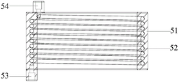
FIG. 3 is a sectional view of a quantitative dispenser of the quantitative dispensing apparatus for biological agents according to the present invention;
FIG. 4 is a flow chart of the method for quantitatively dispensing a biological agent according to the present invention.
Reference numerals are as follows:
10. a storage container; 20. subpackaging the containers; 30. a first non-contact sensor; 40. a second non-contact sensor; 50. a batcher; 51. a body; 52. a flow guide pipe; 53. an inlet; 54. an outlet; 60. a delivery pipe; 70. a peristaltic pump; 80. and (4) switching on and off the valve.
Detailed Description
In order to make the objects, technical solutions and advantages of the present invention more apparent, the technical solutions of the present invention will be clearly and completely described below with reference to the accompanying drawings, and it is obvious that the described embodiments are some, but not all embodiments of the present invention. All other embodiments, which can be derived by a person skilled in the art from the embodiments given herein without making any creative effort, shall fall within the protection scope of the present invention.
In the description of the embodiments of the present invention, it should be noted that the terms "connected" and "connected" are to be interpreted broadly, and may be, for example, a fixed connection, a detachable connection, or an integral connection, unless explicitly stated or limited otherwise; can be mechanically or electrically connected; may be directly connected or indirectly connected through an intermediate. Specific meanings of the above terms in the embodiments of the present invention can be understood in specific cases by those of ordinary skill in the art.
In embodiments of the invention, unless expressly stated or limited otherwise, the first feature "on" or "under" the second feature may be directly contacting the first and second features or indirectly contacting the first and second features through intervening media. Also, a first feature "on," "above," and "over" a second feature may be directly on or obliquely above the second feature, or simply mean that the first feature is at a higher level than the second feature. A first feature "under," "beneath," and "under" a second feature may be directly under or obliquely under the second feature, or may simply mean that the first feature is at a lesser elevation than the second feature.
In the description herein, references to the description of the term "one embodiment," "some embodiments," "an example," "a specific example," or "some examples," etc., mean that a particular feature, structure, material, or characteristic described in connection with the embodiment or example is included in at least one embodiment or example of an embodiment of the invention. In this specification, the schematic representations of the terms used above are not necessarily intended to refer to the same embodiment or example. Furthermore, the particular features, structures, materials, or characteristics described may be combined in any suitable manner in any one or more embodiments or examples. Furthermore, various embodiments or examples and features of different embodiments or examples described in this specification can be combined and combined by one skilled in the art without contradiction.
An embodiment of the present invention will be described below with reference to fig. 1 to 4. It should be understood that the following description is only exemplary of the present invention and is not intended to limit the present invention in any way.
Referring to fig. 1 to 3, a first aspect of the present invention provides a quantitative packaging device for biological agents, wherein the biological agents mainly include cell agents, and biological products processed from effective antigen components of microorganisms and metabolites thereof, animal toxins, blood or tissues of human or animals, etc. for preventing, treating, and diagnosing corresponding infectious diseases or other related diseases.
The biological agent quantitative subpackage device comprises a storage container 10, a subpackage container 20, a first non-contact sensor 30 and a second non-contact sensor 40, wherein the biological agent to be subpackaged is stored in the storage container 10; the liquid inlet of the sub-packaging container 20 is communicated with the liquid outlet of the storage container 10 through a conveying pipe 60; the first non-contact sensor 30 and the second non-contact sensor 40 are both disposed on the delivery pipe 60 between the liquid inlet of the dispensing container 20 and the liquid outlet of the storage container 10, and a predetermined distance is provided between the first non-contact sensor 30 and the second non-contact sensor 40.
The preset distance may be understood as a distance between the first non-contact sensor 30 and the second non-contact sensor 40, which is set at the delivery pipe 60, and the volume or the volume of the delivery pipe 60 between the first non-contact sensor 30 and the second non-contact sensor 40 can be known, so that the actual volume flow rate of the biological agent in the delivery pipe 60 between the first non-contact sensor 30 and the second non-contact sensor 40, which is also the actual flow rate of the biological agent in the delivery pipe 60, can be obtained by detecting and calculating the time difference of the biological agent flowing in the delivery pipe 60, passing through the first non-contact sensor 30 and the second non-contact sensor 40, and by the volume flow rate relationship between the volume or the volume of the delivery pipe 60 between the first non-contact sensor 30 and the second non-contact sensor 40 and the time difference, and further by controlling the time of the biological agent flowing in the delivery pipe 60, the non-contact dispensing of the biological agent can be realized.
It can be understood that, according to the present invention, by providing the first non-contact sensor 30 and the second non-contact sensor 40 on the delivery pipe 60 between the liquid inlet of the dispensing container 20 and the liquid outlet of the storage container 10, after the volume or the volume of the delivery pipe 60 between the first non-contact sensor 30 and the second non-contact sensor 40 is known, the actual volume flow rate of the biological agent in the delivery pipe 60 between the first non-contact sensor 30 and the second non-contact sensor 40 can be obtained by detecting and calculating the time difference between the time when the biological agent flows in the delivery pipe 60 and the time when the biological agent passes through the first non-contact sensor 30 and the second non-contact sensor 40, so that the volumetric dispensing of the biological agent, that is, the quantitative dispensing of the biological agent can be realized by controlling the flowing time of the biological agent in the delivery pipe 60.
As shown in fig. 1 to 3, it can be understood that, in order to further improve the dispensing accuracy of the biological quantitative dispensing apparatus, on the basis of the above-described embodiment, unlike the above-described embodiment, the quantitative section 50 is provided on the delivery pipe 60 between the first non-contact sensor 30 and the second non-contact sensor 40, and the quantitative section 50 is an independent component having certain structural strength and stability, so as to facilitate the biological flow inside the quantitative section 50 and the detection by the non-contact sensor.
As shown in fig. 2 and 3, the container 50 may be made of a resin material, and the structure of the container 50 may be set according to actual use requirements, for example, the container 50 may be in the shape of a cylinder, a cube, a cuboid, a sphere, or the like. When the structure of the quantifier 50 is a cylinder, a through hole can be formed in the middle of the cylinder, so that the section of the cylinder along the radial direction is circular, and the structural design is convenient.
Specifically, the metering device 50 includes a body 51, a flow guide tube 52 is configured inside the body 51, the flow guide tube 52 extends along a preset path, and in order to facilitate connection between the flow guide tube 52 and the delivery pipe 6, an inlet 53 and an outlet 54 are provided on the flow guide tube 52, and the length of the preset path is greater than the linear distance between the inlet 53 and the outlet 54, it can be understood that the preset path is a path through which a pipeline between the inlet 53 and the outlet 54 circulates, and the preset path can be determined according to requirements or the shape of the metering device, and the preset path is configured to extend the distance between the inlet 53 and the outlet 54 of the flow guide tube 52, so as to achieve the effect of accurately measuring the actual volume flow.
As shown in fig. 3, in order to facilitate the processing of the duct 52, the duct 52 may be disposed around the center line of the main body 51, that is, the duct 52 disposed around the center line or the central axis of the main body 51 is configured inside the main body 51, the duct 52 is communicated with the delivery pipe 60, and the duct 52 is configured inside the main body 51, so that the duct 52 may be a rigid pipe and will not deform with the pressure of the medium flowing inside the duct 52, and therefore, the deformation of the delivery pipe 60 due to the excessive liquid pressure in the delivery pipe 60 and the change of the flow rate of the biological agent in the delivery pipe 60 can be avoided, so that the accuracy of quantitative dispensing of the biological agent is poor.
As shown in FIG. 3, to facilitate accurate volume calculations of the delivery tube 6 and the delivery tube 52, the cross-sectional area of the delivery tube 60 and the cross-sectional area of the delivery tube 52 may be set equal.
Of course, the cross-sectional area of the duct 52 and the cross-sectional area of the duct 60 may be set to be different, and the specific setting may be selected according to the actual use situation.
As shown in FIG. 3, in order to more accurately dispense the biological agent, the inlet 53 of the duct 52 is disposed below the main body 51, and the outlet 54 of the duct 52 is disposed above the main body 51, so that the biological agent in the duct 6 enters from below the container 50 and flows out from above the container 50, thereby ensuring that the biological agent can fill the entire duct 52 and improving the calculation accuracy of the volume or the volume of the duct 52.
In addition, a connection section may be provided at the end of the delivery pipe 6, the inner diameters of the passages of the inlet 53 and the outlet 54 are set to be the same as the inner diameter of the delivery pipe 60, and the inner diameter of the connection section is set to be larger than the inner diameters of the passages of the inlet 53 and the outlet 54, so that the delivery pipe 6 may be interference-fitted outside the inlet 53 and the outlet 54 through the connection section provided at the end. In calculating the volume or volume of the delivery tube 60 between the first and second non-contact sensors 30, 40, the length and inner diameter of the delivery tube 60 between the first and second non-contact sensors 30, 40 can be determined directly.
In addition, in order to improve the sealability between the delivery pipe 6 and the inlet 53 and the outlet 54 of the draft tube 52, the delivery pipe 6 may be screwed to the inlet 53 and the outlet 54 of the draft tube 52.
When the quantifier 50 is manufactured, the volume or volume of the delivery tube 52 is known and fixed, and therefore, when calculating the volume or volume of the delivery tube 60 between the first non-contact sensor 30 and the second non-contact sensor 40, it is more convenient to calculate the volume or volume of the delivery tube 60 between the inlet 53 of the quantifier 50 and the first non-contact sensor 30, and to calculate the volume or volume of the delivery tube 60 between the outlet 54 of the quantifier 50 and the second non-contact sensor 40.
In the quantitative subpackaging process of the embodiment, the storage container 10 can be arranged above the subpackaging container 20, that is, the height of the horizontal plane of the liquid outlet of the storage container 10 is larger than the height of the horizontal plane of the liquid inlet of the subpackaging container 20, so that the biological agent stored in the storage container 10 automatically enters the conveying pipe 60 under the action of gravity. When the biological agent moves along the delivery tube 60 and passes through the position of the first non-contact sensor 30, the first non-contact sensor 30 detects the biological agent, and records the first time of the detected first bubble detection signal; the cell preparation continues to move along the delivery tube 60, the second non-contact sensor 40 detects the biological preparation when the cell preparation passes the position of the second non-contact sensor 40, the second time of the second bubble detection signal detected at this time is recorded, and the difference obtained by subtracting the first time from the recorded second time is the time difference of the cell preparation flowing in the delivery tube 60 and passing through the first non-contact sensor 30 and the second non-contact sensor 40.
Based on the time difference and the volume or volume of the delivery tube 60 (including the volume or volume of the delivery tube 52 and including a portion of the volume or volume of the delivery tube 60) between the first and second non-contact sensors 30 and 40, the actual flow rate of the biological agent in the delivery tube 60 is obtained by a volume flow calculation formula, and thus, the actual volume of the biological agent in the dispensing container 20 can be obtained by calculating the time for the biological agent to flow through the first or second non-contact sensors 30 and 40, i.e., the dispensing of the biological agent can be metered.
In some embodiments of the present invention, different from the above embodiments, in order to avoid the flow rate of the biological agent in the delivery pipe 60 being too high and the flow rate of the biological agent passing through the first non-contact sensor 30 and the second non-contact sensor 40 being too high to be detected accurately, the delivery pipe 60 between the first non-contact sensor 30 and the second non-contact sensor 40 may be disposed in a spiral shape to extend the flow path of the delivery pipe 60 between the first non-contact sensor 30 and the second non-contact sensor 40, that is, to extend the time period of the biological agent flowing on the delivery pipe 60 between the first non-contact sensor 30 and the second non-contact sensor 40, so as to more accurately detect the time difference of the biological agent passing through the first non-contact sensor 30 and the second non-contact sensor 40 when the biological agent flows in the delivery pipe 60.
As shown in fig. 1, as an embodiment of the present invention, on the basis of the above-described embodiment, in order to make the flow rate in the transfer pipe 60 more stable and uniform, the dispensing apparatus for quantitatively dispensing a biological agent further includes a pumping member for supplying a transfer power to the transfer pipe 60, and the pumping member may be provided on any one of the transfer pipe 60, the storage container 10 and the dispensing container 20, unlike the above-described embodiment.
For example, when the pumping element is a peristaltic pump 70, as if the delivery tube 60 filled with the biological agent is pinched by a finger, the biological agent in the delivery tube 60 moves forward as the finger slides forward. The peristaltic pump 70 replaces the fingers with rollers to pump the biological agent by alternately squeezing and releasing the delivery tube 60 secured in the peristaltic pump 70.
Wherein a peristaltic pump 70 may be disposed on the delivery tube 60 between the storage container 10 and the first non-contact sensor 30; a peristaltic pump 70 may also be provided on the delivery tube 60 between the dispensing container 20 and the second non-contact sensor 40.
To make the peristaltic pump 70 control more accurate, the peristaltic pump 70 is disposed in front of the inlet 53 of the doser 50, i.e., the peristaltic pump 70 is disposed on the delivery tube 60 between the storage container 10 and the first non-contact sensor 30.
For example, when the pumping member is an air pump, the air pump may be installed on the storage container 10, and the pressure in the storage container 10 may be increased by the air pump, so that the biological agent in the storage container 10 can enter the delivery tube 60.
For example, when the pumping means is a vacuum pump, the vacuum pump may be installed in the dispensing container 20, and the vacuum pump evacuates air in the dispensing container 20 to make the dispensing container 20 in a negative pressure state, so that the biological agent in the adsorption storage container 10 can enter the transfer tube 60.
As shown in fig. 1, as an embodiment of the present invention, different from the above-described embodiment, one dispensing container 20 may be provided, and after one dispensing container 20 is dispensed quantitatively, the next dispensing container 20 may be replaced to continue the quantitative dispensing.
The plurality of the sub-packaging containers 20 may be arranged in parallel, and the transfer pipe 60 between the liquid inlet of each sub-packaging container 20 and the liquid outlet of the storage container 10 is provided with a switch valve 80.
Namely, the sub-packaging containers 20 are sequentially provided with a first sub-packaging container, a second sub-packaging container, a third sub-packaging container \8230 \ 8230and an Nth sub-packaging container, etc., and the conveying pipe 60 at the inlet of each sub-packaging container 20 is provided with a switch valve 80, namely, the first sub-packaging container corresponds to the first switch valve, and the Nth sub-packaging container corresponds to the Nth switch valve.
Equivalently, a main conveying pipe is arranged between a liquid inlet of the first sub-packaging container and a liquid outlet of the storage container 10, the second sub-packaging container and the third sub-packaging container \8230, the liquid inlet of the Nth sub-packaging container is provided with an additional branch conveying pipe, and a switch valve is arranged on the branch conveying pipe.
The switch valve 80 is an electromagnetic pinch valve (pinch valve for short), and is driven by an electromagnetic solenoid, the on-off of the delivery pipe 60 is controlled by squeezing or loosening the delivery pipe 60, the biological agent only passes through the delivery pipe 60, and other parts of the pinch valve are not contacted with the biological agent, so that the non-contact quantitative split charging of the biological agent is convenient to realize.
In this embodiment, after the actual flow rate of the biological agent in the delivery pipe 60 is obtained through the first non-contact sensor 30 and the second non-contact sensor 40, the flow rate of the peristaltic pump 70 may be calibrated, so that the flow rate of the biological agent in the delivery pipe 60 tends to be stable, and thus the actual volume or volume of the biological agent filled in the dispensing container 20 may be indirectly known by controlling the opening time of the corresponding on-off valve 80 on the dispensing container 20, so as to achieve quantitative dispensing of the biological agent.
In the embodiment of the present invention, the first non-contact sensor 30 and the second non-contact sensor 40 are both bubble sensors, and are used for monitoring bubbles in the delivery pipe 60 in real time to feed back the time of the bubbles in the delivery pipe 60.
The bubble sensor can adopt a snap-in mode to install the delivery pipe 60, the delivery pipe 60 does not need to be cut off, the subpackaged biological agents are not polluted, and the non-contact subpackaging requirement of the biological agents is met. Moreover, the bubble sensor can be matched with the peristaltic pump 70 by using a 12V power supply in the peristaltic pump 70 without an external power supply, so that the operation is more convenient.
In the embodiment of the present invention, the bubble sensor may perform detection by using infrared detection, capacitance detection, and ultrasonic detection, that is, the first non-contact sensor 30 and the second non-contact sensor 40 may be a capacitive sensor, an ultrasonic sensor, or a separate photoelectric sensor.
In the embodiment of the present invention, the storage container 10 and the dispensing container 20 may be tubular or bag-type containers, such as a liquid bag, a liquid tube, a liquid distribution bag and a liquid distribution tube. The delivery tube 60 is a flexible tube that facilitates the clamping of the peristaltic pump 70 and the non-contact sensor.
Referring to fig. 1 and 4, a second aspect of the present invention provides a quantitative packaging method for biological agents, which uses a quantitative packaging device for biological agents as follows:
two bubble sensors (namely a first bubble sensor and a second bubble sensor) with the same specification, a peristaltic pump 70, a batcher 50 (the volume of the batcher 50 is known), a plurality of conveying pipes 60, a plurality of liquid dividing bags and a plurality of pinch valves corresponding to the liquid dividing belts are selected. After a plurality of liquid separating bags are connected in parallel, the liquid separating bags are connected with a liquid outlet of the liquid storage bag through a conveying pipe 60, the batcher 50 is connected with the conveying pipe 60 between the liquid inlet of the liquid separating bag closest to the liquid storage bag and the liquid outlet of the liquid storage bag, two bubble sensors with the same specification are clamped at two ends of an inlet 53 and an outlet 54 of the batcher 50, the peristaltic pump 70 is arranged on the conveying pipe 60 between the first bubble sensor and the liquid storage bag, and a pinch valve is clamped on each conveying pipe 60 of the liquid separating bags.
Before dispensing the biological agent in the liquid storage bag, air in the liquid separation bag and the delivery pipe 60 is pumped into the liquid storage bag by using the peristaltic pump 70, so that the excessive air is prevented from occupying the volume of the liquid separation bag or the delivery pipe, and the dispensing precision of the liquid separation bag is further influenced.
The quantitative subpackaging method of the biological preparation mainly comprises the following steps:
step S10: a first bubble detection signal of the biological agent flowing in the delivery tube 60 detected by the first non-contact sensor 30 is acquired.
I.e., after calibrating the flow rate of the peristaltic pump 70, to ensure that the flow rate of the biological agent in the delivery tube 60 is stable. The biological agent in the liquid storage bag flows into the conveying pipe 60 from the liquid storage bag under the pumping action of the peristaltic pump 70, the biological agent flows to the position where the biological agent passes through the first bubble sensor along the conveying pipe 60, and the first bubble sensor transmits a detected first bubble detection signal to the controller for storage.
Step S20: acquiring a second bubble detection signal of the bio-formulation flowing through the delivery tube 60 detected by the second non-contact sensor 40;
the biological agent flows to the first bubble sensor along the delivery pipe 60 and enters the batcher 50, and when the biological agent is full of the draft tube 52 of the batcher 50, the biological agent flows out of the batcher 50 and enters the other delivery pipe 60, and passes through the position of the second bubble sensor, and the second bubble sensor transmits the detected second bubble detection signal to the controller for storage;
step S30: calculating a time difference t between the detected first and second bubble detection signals;
that is, the controller stores the time when the biological agent passes through the first bubble sensor and the second bubble sensor while flowing in the delivery pipe 60, and calculates the time difference t when the biological agent passes through the entire scale 50 and a portion of the delivery pipe 60 while flowing in the delivery pipe 60.
Step S40: the actual flow rate of the biological agent in the delivery pipe 60 is obtained by the relationship between the time difference t and the volume or the volume of the delivery pipe 60 (including the delivery pipe 52 and the part of the delivery pipe 60) between the first non-contact sensor 30 and the second non-contact sensor 40;
adding the volume of the batcher 50, the volume of the delivery pipe 60 between the first bubble sensor and the inlet 53 of the batcher 50, and the volume of the delivery pipe 60 between the second bubble sensor and the outlet 54 of the batcher 50 to obtain the total volume of the delivery pipe 60 between the first bubble sensor and the second bubble sensor, and dividing the total volume by the time difference t to obtain the actual volume flow Q of the biological agent in the delivery pipe 60 at the moment;
the volume flow of the invention is expressed by the formula: qv = V/t = uxA (1-1)
In the formula: v represents a unit flow volume;
t represents a bit time;
u represents the average flow velocity in the tube;
a represents the cross-sectional area of the conduit.
Step S50: the time for the biological agent to flow in the duct 60 is controlled to achieve quantitative dispensing of the biological agent.
After the flow of the peristaltic pump 70 is calibrated, that is, after the flow rate of the biological agent in the delivery pipe 60 is determined, the actual volume of the biological agent entering the corresponding liquid separation bag is controlled by controlling the opening and closing time of the pinch valve on each liquid separation bag, so that the quantitative subpackaging of the biological agent is realized. The subpackaging process is carried out in sequence from the first liquid separating bag to the Nth liquid separating bag.
In some embodiments of the present invention, in the step S50, the flow time of the biological agent in the delivery pipe 60 is controlled to achieve quantitative dispensing of the biological agent at a preset flow rate of the peristaltic pump 70, which is a stable flow rate of the peristaltic pump 70 after calibration, and the opening and closing time of the on-off valve 80 at the inlet of each dispensing container 20 is controlled to achieve quantitative dispensing.
For example, the volume of the biological agent stored in the liquid storage bag is 304ml, the biological agent needs to be packed into 6 liquid distribution bags, the volume of the known doser 50 is 5ml, the flow rate of the peristaltic pump 70 is 24ml/min, the volume of the delivery pipe 60 between the second bubble sensor and the liquid inlet of the sixth liquid distribution bag is 1.5ml, and the volume of the branch delivery pipe between the liquid inlet of the other liquid distribution bags and the main delivery pipe is 0.5ml.
When the biological agent is dispensed, the biological agent flows to pass through the first bubble sensor along the delivery pipe 60 and enters the batcher 50, the biological agent flows out of the batcher 50 and enters another delivery pipe 60 after the biological agent is filled in the draft tube 52 of the batcher 50 and passes through the position of the second bubble sensor, the second bubble sensor transmits the detected second bubble detection signal to the controller for storage, the time difference between the second bubble detection signal and the first bubble detection signal is calculated to be 12s, and the actual flow velocity of the biological agent in the delivery pipe 60 at the moment is calculated to be 5ml/12s =25ml/min through a volume flow meter formula.
If the volume of each liquid distribution bag is 50ml, the time required for subpackaging the last liquid distribution bag, namely the sixth liquid distribution bag is (50 + 1.5)/25 =123.6s, and the time required for subpackaging the other 5 liquid distribution bags is (50 + 0.5)/25 =121.2s.
The invention calculates the actual liquid inlet flow of the biological preparation in the delivery pipe 60 by measuring the relationship between the time of the biological preparation flowing through one batcher 50 and the volume of the batcher 50 through two bubble sensors with consistent specifications, calibrates the rotating speed of the peristaltic pump 70 through the actual liquid inlet flow of the biological preparation in the delivery pipe 60, and further determines the true volume or volume of the biological preparation in the liquid separating bag by controlling the biological preparation to enter the liquid separating bag under the set flow of the peristaltic pump 70, namely the stable flow speed of the delivery pipe 60, so as to realize the non-contact sub-packaging of the biological preparation.
It should be noted that the flow rate of the peristaltic pump 70 is the volume of the biological agent flowing through the peristaltic pump 70 per unit time, and the flow rate and the rotation speed of the peristaltic pump 70 are in direct proportion.
The invention measures the actual flow of the biological agent in the delivery pipe 60 by combining two bubble sensors with the same specification and the batcher 50 so as to calibrate the rotating speed of the peristaltic pump 70, thereby improving the subpackaging precision and efficiency of the biological agent.
The present invention indirectly measures the actual flow rate in the delivery tube 60 by the relationship between the volume of the biological agent in the delivery tube 60 and the time of the biological agent flowing in the delivery tube 60 of a preset length to calibrate the flow rate of the peristaltic pump 70, and thus the flow rate of the peristaltic pump 70. In the case of determining the actual flow rate in the delivery pipe 60, the biological agent is quantitatively dispensed by controlling the flow time of the biological agent in the delivery pipe 60.
In addition, the quantitative biological agent subpackaging method provided by the invention can avoid the error caused by vibration or shaking of the quantitative biological agent subpackaging device in the subpackaging process so as to realize accurate control of the subpackaging volume of the biological agent, the whole subpackaging process is not in direct contact with the biological agent, the integrity and the activity of the biological agent cannot be damaged, and the practicability is strong.
It should be noted that the technical solutions in the embodiments of the present invention may be combined with each other, but the basis of the combination is that those skilled in the art can implement the combination; when the technical solutions are mutually contradictory or cannot be realized, the combination of the technical solutions is not considered to exist, and the technical solutions do not belong to the protection scope of the present invention.
Finally, it should be noted that: the above examples are only intended to illustrate the technical solution of the present invention, but not to limit it; although the present invention has been described in detail with reference to the foregoing embodiments, it should be understood by those of ordinary skill in the art that: the technical solutions described in the foregoing embodiments may still be modified, or some technical features may be equivalently replaced; and such modifications or substitutions do not depart from the spirit and scope of the corresponding technical solutions of the embodiments of the present invention.
Claims (10)
1. A biological agent quantitative subpackage device is characterized by comprising:
a storage container having a biological agent stored therein;
the liquid inlet of the split charging container is communicated with the liquid outlet of the storage container through a conveying pipe;
the liquid storage container comprises a first non-contact sensor and a second non-contact sensor, wherein the first non-contact sensor and the second non-contact sensor are arranged on a conveying pipe between a liquid inlet of the sub-packaging container and a liquid outlet of the storage container, and a preset distance is arranged between the first non-contact sensor and the second non-contact sensor.
2. The metered dose dispensing apparatus of claim 1, wherein a doser is provided on the transfer tube between the first non-contact sensor and the second non-contact sensor.
3. The biological agent quantitative subpackaging device according to claim 2, wherein the batcher comprises a body, a flow guide pipe is configured inside the body, the flow guide pipe extends along a preset path, and the length of the preset path is greater than the distance between the inlet of the flow guide pipe and the outlet of the flow guide pipe.
4. The dispensing apparatus for quantitatively dispensing biological agents as set forth in claim 3 wherein the guide pipe is circumferentially disposed along a center line of the body and communicates with the delivery pipe.
5. The device as claimed in claim 4, wherein the cross-sectional area of the flow guide tube is equal to the cross-sectional area of the delivery tube.
6. The metered dose dispensing apparatus of claim 1, wherein the duct between the first non-contact sensor and the second non-contact sensor is configured in a spiral shape and adapted to extend a flow path of the duct.
7. The metered dose dispensing apparatus of claim 1, further comprising a pumping member for providing a delivery power to said delivery tube, said pumping member being provided on any one of said delivery tube, said storage container and said dispensing container.
8. The biological agent quantitative subpackaging device according to claim 1, wherein a plurality of the subpackaging containers are arranged in parallel, and a switch valve is respectively arranged on the conveying pipe between the liquid inlet of each subpackaging container and the liquid outlet of the storage container.
9. A quantitative subpackage method for biological agents is characterized by comprising the following steps:
acquiring a first bubble detection signal of the conveying pipe detected by a first non-contact sensor;
acquiring a second bubble detection signal of the conveying pipe detected by a second non-contact sensor;
calculating a time difference of the detected first and second bubble detection signals;
obtaining an actual volumetric flow rate of the biological agent in the delivery tube from a relationship between the time difference and a volume of the delivery tube between the first non-contact sensor and the second non-contact sensor;
the flowing time of the biological agent in the conveying pipe is controlled to realize the quantitative subpackage of the biological agent.
10. The method for quantitatively dispensing biological agents according to claim 9, wherein the controlling of the flowing time of the biological agents in the conveying pipe to achieve the quantitative dispensing of the biological agents is to control the on-off time of an on-off valve at the inlet of each dispensing container at a preset flow rate of a peristaltic pump.
Priority Applications (2)
| Application Number | Priority Date | Filing Date | Title |
|---|---|---|---|
| CN202211139803.6A CN115583370A (en) | 2022-09-19 | 2022-09-19 | Biological agent quantitative subpackaging device and method |
| PCT/CN2023/116549 WO2024060969A1 (en) | 2022-09-19 | 2023-09-01 | Biological agent quantitative dispensing device and dispensing method |
Applications Claiming Priority (1)
| Application Number | Priority Date | Filing Date | Title |
|---|---|---|---|
| CN202211139803.6A CN115583370A (en) | 2022-09-19 | 2022-09-19 | Biological agent quantitative subpackaging device and method |
Publications (1)
| Publication Number | Publication Date |
|---|---|
| CN115583370A true CN115583370A (en) | 2023-01-10 |
Family
ID=84778209
Family Applications (1)
| Application Number | Title | Priority Date | Filing Date |
|---|---|---|---|
| CN202211139803.6A Pending CN115583370A (en) | 2022-09-19 | 2022-09-19 | Biological agent quantitative subpackaging device and method |
Country Status (2)
| Country | Link |
|---|---|
| CN (1) | CN115583370A (en) |
| WO (1) | WO2024060969A1 (en) |
Cited By (1)
| Publication number | Priority date | Publication date | Assignee | Title |
|---|---|---|---|---|
| WO2024060969A1 (en) * | 2022-09-19 | 2024-03-28 | 深圳赛桥生物创新技术有限公司 | Biological agent quantitative dispensing device and dispensing method |
Family Cites Families (7)
| Publication number | Priority date | Publication date | Assignee | Title |
|---|---|---|---|---|
| EP1533597A1 (en) * | 2003-11-20 | 2005-05-25 | Millipore Corporation | Fluid dispensing device |
| CN101614569B (en) * | 2009-07-20 | 2011-09-21 | 北京工业大学 | Method for measuring liquid capacity of pipeline based on ultrasonic guided wave technology |
| US11357966B2 (en) * | 2015-04-23 | 2022-06-14 | B. Braun Medical Inc. | Compounding device, system, kit, software, and method |
| CN204643801U (en) * | 2015-05-27 | 2015-09-16 | 广东天普生化医药股份有限公司 | Semi-automatic machine for feeding bottles |
| CN111483631A (en) * | 2020-05-19 | 2020-08-04 | 楚天科技股份有限公司 | Filling system and filling method |
| CN111505173B (en) * | 2020-06-12 | 2020-12-08 | 赛默飞世尔(上海)仪器有限公司 | Method for determining liquid flow, fraction collector and liquid chromatography system |
| CN115583370A (en) * | 2022-09-19 | 2023-01-10 | 深圳赛桥生物创新技术有限公司 | Biological agent quantitative subpackaging device and method |
-
2022
- 2022-09-19 CN CN202211139803.6A patent/CN115583370A/en active Pending
-
2023
- 2023-09-01 WO PCT/CN2023/116549 patent/WO2024060969A1/en unknown
Cited By (1)
| Publication number | Priority date | Publication date | Assignee | Title |
|---|---|---|---|---|
| WO2024060969A1 (en) * | 2022-09-19 | 2024-03-28 | 深圳赛桥生物创新技术有限公司 | Biological agent quantitative dispensing device and dispensing method |
Also Published As
| Publication number | Publication date |
|---|---|
| WO2024060969A1 (en) | 2024-03-28 |
Similar Documents
| Publication | Publication Date | Title |
|---|---|---|
| US4252115A (en) | Apparatus for periodically rinsing body cavities, particularly the abdominal cavity | |
| JP6534633B2 (en) | Infusion pump with tube measurement technology using linear actuator and pressure sensor | |
| EP1144961B1 (en) | Droplet counter for low flow rates | |
| CN101652639B (en) | Metering device for an infusion system | |
| US20030159741A1 (en) | Fluid delivery system and method | |
| US9482563B2 (en) | Real time measurements of fluid volume and flow rate using two pressure transducers | |
| US8863986B2 (en) | Time volumetric fluid dispensing apparatus | |
| CA2643907A1 (en) | Volume measurement using gas laws | |
| WO2011017667A2 (en) | Two chamber pumps and related methods | |
| CN205411785U (en) | A controlgear that is used for confirming flow rate with adjustment blood delivery pump during annotating in advance | |
| JP2002534224A (en) | Injector for liquid dosing with pressure measuring system | |
| US7104422B2 (en) | Fluid dispensing apparatus having means for measuring fluid volume continuously | |
| CN115583370A (en) | Biological agent quantitative subpackaging device and method | |
| JP6830495B2 (en) | Injection method and filling machine | |
| EP2062605A1 (en) | Calibrating device for dosing machines of radioactive substances | |
| EP1600746A2 (en) | Fluid dispenser cartridge with bladder means | |
| US20130322201A1 (en) | Compounding apparatus and method | |
| JP7180949B2 (en) | Manifolds for buffer management systems, dilution skids and methods of using buffer management systems | |
| ES2942907T3 (en) | Fluid supply assembly for removing gas bubbles from a fluid path | |
| ES2945413T3 (en) | Process for producing a medicinal preparation | |
| ES2945432T3 (en) | Procedure for producing a medicinal preparation using a peristaltic pump | |
| US7228992B2 (en) | Fluid dispenser cartridge | |
| US8087596B2 (en) | Device and method for metering media | |
| JP6025191B2 (en) | Radiopharmaceutical administration device | |
| TR202022840A2 (en) | VEHICLE COUNTING THE AMOUNT OF URINE |
Legal Events
| Date | Code | Title | Description |
|---|---|---|---|
| PB01 | Publication | ||
| PB01 | Publication | ||
| SE01 | Entry into force of request for substantive examination | ||
| SE01 | Entry into force of request for substantive examination |