CN115580098B - Linear rotation permanent magnet motor with linear motion axis perpendicular to rotation motion axis - Google Patents
Linear rotation permanent magnet motor with linear motion axis perpendicular to rotation motion axis Download PDFInfo
- Publication number
- CN115580098B CN115580098B CN202211564313.0A CN202211564313A CN115580098B CN 115580098 B CN115580098 B CN 115580098B CN 202211564313 A CN202211564313 A CN 202211564313A CN 115580098 B CN115580098 B CN 115580098B
- Authority
- CN
- China
- Prior art keywords
- linear
- rotary
- motion
- permanent magnet
- motion axis
- Prior art date
- Legal status (The legal status is an assumption and is not a legal conclusion. Google has not performed a legal analysis and makes no representation as to the accuracy of the status listed.)
- Active
Links
- XEEYBQQBJWHFJM-UHFFFAOYSA-N Iron Chemical group [Fe] XEEYBQQBJWHFJM-UHFFFAOYSA-N 0.000 claims abstract description 74
- 230000007246 mechanism Effects 0.000 claims abstract description 26
- 229910052742 iron Inorganic materials 0.000 claims abstract description 21
- 230000005415 magnetization Effects 0.000 claims description 13
- 230000000694 effects Effects 0.000 claims 1
- 235000000396 iron Nutrition 0.000 claims 1
- 230000004044 response Effects 0.000 abstract description 6
- 238000000034 method Methods 0.000 abstract description 5
- 230000008569 process Effects 0.000 abstract description 3
- 238000010586 diagram Methods 0.000 description 6
- 238000004804 winding Methods 0.000 description 4
- 238000004519 manufacturing process Methods 0.000 description 2
- 230000004048 modification Effects 0.000 description 2
- 238000012986 modification Methods 0.000 description 2
- 230000009286 beneficial effect Effects 0.000 description 1
- 230000007123 defense Effects 0.000 description 1
- 239000012636 effector Substances 0.000 description 1
- 238000005516 engineering process Methods 0.000 description 1
- 230000005284 excitation Effects 0.000 description 1
- 230000010354 integration Effects 0.000 description 1
- 239000000463 material Substances 0.000 description 1
- 229910052761 rare earth metal Inorganic materials 0.000 description 1
- 150000002910 rare earth metals Chemical class 0.000 description 1
- 238000006467 substitution reaction Methods 0.000 description 1
- 239000000725 suspension Substances 0.000 description 1
Images


Classifications
-
- H—ELECTRICITY
- H02—GENERATION; CONVERSION OR DISTRIBUTION OF ELECTRIC POWER
- H02K—DYNAMO-ELECTRIC MACHINES
- H02K16/00—Machines with more than one rotor or stator
-
- H—ELECTRICITY
- H02—GENERATION; CONVERSION OR DISTRIBUTION OF ELECTRIC POWER
- H02K—DYNAMO-ELECTRIC MACHINES
- H02K21/00—Synchronous motors having permanent magnets; Synchronous generators having permanent magnets
- H02K21/12—Synchronous motors having permanent magnets; Synchronous generators having permanent magnets with stationary armatures and rotating magnets
- H02K21/14—Synchronous motors having permanent magnets; Synchronous generators having permanent magnets with stationary armatures and rotating magnets with magnets rotating within the armatures
-
- H—ELECTRICITY
- H02—GENERATION; CONVERSION OR DISTRIBUTION OF ELECTRIC POWER
- H02K—DYNAMO-ELECTRIC MACHINES
- H02K41/00—Propulsion systems in which a rigid body is moved along a path due to dynamo-electric interaction between the body and a magnetic field travelling along the path
- H02K41/02—Linear motors; Sectional motors
- H02K41/03—Synchronous motors; Motors moving step by step; Reluctance motors
- H02K41/031—Synchronous motors; Motors moving step by step; Reluctance motors of the permanent magnet type
Landscapes
- Engineering & Computer Science (AREA)
- Power Engineering (AREA)
- Physics & Mathematics (AREA)
- Chemical & Material Sciences (AREA)
- Combustion & Propulsion (AREA)
- Electromagnetism (AREA)
- Linear Motors (AREA)
- Reciprocating, Oscillating Or Vibrating Motors (AREA)
Abstract
本发明公开了一种直线运动轴线与旋转运动轴线垂直的直线旋转永磁电机,包括定子机构和动子机构,所述定子机构包括两个侧边线圈、两个侧边铁芯、一个中部线圈、一个中部铁芯和两个连接铁轭,所述侧边线圈绕设在侧边铁芯上,两个所述连接铁轭和两个所述侧边铁芯围成一个环形结构,所述连接铁轭与侧边铁芯交错设置,本发明与常规直线旋转电机不同,该电机的直线运动轴线与旋转运动轴线垂直,用以满足多维精密复杂运动平台的特殊需求,动子质量轻、运动过程不拖动电缆,动态响应速度快,电机结构简洁,结构简单,适用于多维精密运动系统,电机解耦控制方便,极大地提高了电机运行中直线运动和旋转运动的精度。
The invention discloses a linear rotary permanent magnet motor whose linear motion axis is perpendicular to the rotary motion axis, comprising a stator mechanism and a mover mechanism, and the stator mechanism includes two side coils, two side iron cores, and a middle coil , a middle iron core and two connecting iron yokes, the side coils are wound on the side iron cores, the two connecting iron yokes and the two side iron cores form a ring structure, the said The connecting iron yoke and the side iron core are arranged alternately. This invention is different from the conventional linear rotary motor. The linear motion axis of the motor is perpendicular to the rotary motion axis to meet the special needs of multi-dimensional precision and complex motion platforms. The process does not drag the cable, the dynamic response speed is fast, the motor structure is simple and simple, and it is suitable for multi-dimensional precision motion systems. The decoupling control of the motor is convenient, which greatly improves the accuracy of linear motion and rotary motion during motor operation.
Description
技术领域technical field
本发明涉及永磁电机技术领域,具体为一种直线运动轴线与旋转运动轴线垂直的直线旋转永磁电机。The invention relates to the technical field of permanent magnet motors, in particular to a linear rotary permanent magnet motor whose linear motion axis is perpendicular to the rotational motion axis.
背景技术Background technique
永磁电机是指以永磁体励磁生成电机主磁场的电机,其可为交流电机也可为直流电机。对旋转型永磁电机而言,通常定子是线圈,转子是永磁体;对直线型永磁电机而言,定、动子结构可有多种选择。永磁体充磁后,制成电机次级,不需外界能量即可维持其主极磁场。近年来,采用稀土材料制作永磁体,使得永磁电机具有结构简单,运行可靠;体积小,质量轻;损耗小,效率高;电机的形状和尺寸可以灵活多样等显著优点,因而应用范围极为广泛,几乎遍及航空航天、国防、工农业和产和日常生活的各个领域。A permanent magnet motor refers to a motor that uses permanent magnet excitation to generate the main magnetic field of the motor, which can be either an AC motor or a DC motor. For rotary permanent magnet motors, usually the stator is a coil and the rotor is a permanent magnet; for linear permanent magnet motors, there are many options for the stator and mover structures. After the permanent magnet is magnetized, it is made into the secondary side of the motor, and its main pole magnetic field can be maintained without external energy. In recent years, the use of rare earth materials to make permanent magnets has made permanent magnet motors have significant advantages such as simple structure, reliable operation, small size, light weight, low loss, and high efficiency; the shape and size of the motor can be flexible and diverse, so the application range is extremely wide , Almost all fields of aerospace, national defense, industry, agriculture and production and daily life.
经检索,申请号为202210496564.3的专利公开了一种直线旋转永磁电机,包括用于安装转轴以及磁铁的电机转子组件,所述磁铁沿所述转轴的径向同极等间距间隔分布,所述磁铁沿所述转轴的轴向相邻异极等间距间隔分布,还包括由叠压固定在电机壳体内壁的直线运动绕组以及旋转运动绕组的电机定子组件,所述直线运动绕组位于所述旋转运动绕组的外部呈等间距间隔分布。该直线旋转永磁电机,在跳出传统机械拼凑或者集成的方式,通过交错分布的磁路形式,让电机产生直线和旋转方向上的动力。该发明结构紧凑、体积小;轻量化的转子让电机具有更小的惯量,从而具备更大的运动速度;结构简单,制造成本低。After retrieval, the patent application number 202210496564.3 discloses a linear rotary permanent magnet motor, including a motor rotor assembly for installing a rotating shaft and magnets, and the magnets are distributed at equal intervals along the radial direction of the rotating shaft at the same poles. The magnets are distributed at equal intervals between adjacent different poles in the axial direction of the rotating shaft, and also include a motor stator assembly composed of linear motion windings and rotary motion windings laminated and fixed on the inner wall of the motor housing, and the linear motion windings are located on the The outer portions of the rotating motion windings are equally spaced apart. The linear rotary permanent magnet motor breaks away from the traditional mechanical patchwork or integration method, and allows the motor to generate power in the linear and rotational directions through the form of staggered magnetic circuits. The invention has a compact structure and a small volume; the lightweight rotor allows the motor to have a smaller inertia, thereby having a greater movement speed; the structure is simple and the manufacturing cost is low.
上述方案中的直线旋转永磁电机属于常规的直线运动轴线与旋转运动轴线平行的直线旋转电机,不能满足多维精密复杂运动平台末端执行器对推力/扭矩的平稳度、电机动子的高响应速度、直线运动轴线与旋转运动轴线相对位置多样性等特殊需求,且电机运行中直线运动和旋转运动的精度低,因此我们需要提出一种直线运动轴线与旋转运动轴线垂直的直线旋转永磁电机。The linear rotary permanent magnet motor in the above scheme belongs to the conventional linear rotary motor whose axis of linear motion is parallel to the axis of rotary motion, which cannot meet the stability of the thrust/torque of the end effector of the multi-dimensional precision and complex motion platform and the high response speed of the motor mover. , the relative position diversity of the linear motion axis and the rotary motion axis and other special requirements, and the accuracy of the linear motion and rotary motion during the motor operation is low, so we need to propose a linear rotary permanent magnet motor whose linear motion axis is perpendicular to the rotary motion axis.
发明内容Contents of the invention
本发明的目的在于提供一种直线运动轴线与旋转运动轴线垂直的直线旋转永磁电机,与常规直线旋转电机不同,该电机的直线运动轴线与旋转运动轴线垂直,用以满足多维精密复杂运动平台的特殊需求,动子质量轻、运动过程不拖动电缆,动态响应速度快,电机结构简洁,结构简单,适用于多维精密运动系统,电机解耦控制方便,极大地提高了电机运行中直线运动和旋转运动的精度,以解决上述背景技术中提出的问题。The object of the present invention is to provide a linear rotary permanent magnet motor whose linear motion axis is perpendicular to the rotary motion axis. The special needs of the special requirements, the mover is light in weight, the cable is not dragged during the movement process, the dynamic response speed is fast, the motor structure is simple and simple, suitable for multi-dimensional precision motion systems, the motor decoupling control is convenient, and the linear motion during the motor operation is greatly improved. and the precision of the rotary motion to solve the problems raised in the above-mentioned background technology.
为实现上述目的,本发明提供如下技术方案:一种直线运动轴线与旋转运动轴线垂直的直线旋转永磁电机,包括定子机构和动子机构,所述定子机构包括两个侧边线圈、两个侧边铁芯、一个中部线圈、一个中部铁芯和两个连接铁轭,所述侧边线圈绕设在侧边铁芯上,两个所述连接铁轭和两个所述侧边铁芯围成一个环形结构,所述连接铁轭与侧边铁芯交错设置,所述中部铁芯连接在两个所述连接铁轭之间,所述中部线圈绕设在中部铁芯上;所述动子机构包括两块侧边永磁体、一块中部永磁体和一个动子支架,所述动子支架活动安装在定子机构的上端,两块所述侧边永磁体安装在动子支架的两端,所述中部永磁体安装在动子支架的中部。To achieve the above object, the present invention provides the following technical solution: a linear rotary permanent magnet motor whose linear motion axis is perpendicular to the rotary motion axis, including a stator mechanism and a mover mechanism, and the stator mechanism includes two side coils, two side iron core, a middle coil, a middle iron core and two connecting iron yokes, the side coil is wound on the side iron core, the two connecting iron yokes and the two side iron cores Surrounding a ring structure, the connecting iron yokes and the side iron cores are alternately arranged, the middle iron core is connected between the two connecting iron yokes, and the middle coil is wound on the middle iron core; The mover mechanism includes two side permanent magnets, a middle permanent magnet and a mover bracket, the mover bracket is movably installed on the upper end of the stator mechanism, and the two side permanent magnets are installed at both ends of the mover bracket , the middle permanent magnet is installed in the middle of the mover bracket.
优选的,两个所述连接铁轭的侧部均连接有滑轨支架,两个所述滑轨支架上连接有直线滑轨,所述动子支架可沿着直线滑轨滑动。Preferably, slide rail brackets are connected to the sides of the two connecting iron yokes, linear slide rails are connected to the two slide rail brackets, and the mover brackets can slide along the linear slide rails.
优选的,所述直线滑轨的下端安装有直线滑块,所述动子支架通过转动轴承转动安装在直线滑块的下端。Preferably, a linear slider is installed on the lower end of the linear slide rail, and the mover bracket is rotatably mounted on the lower end of the linear slider through a rotating bearing.
优选的,所述转动轴承嵌设在直线滑块上,所述转动轴承的内圈插接有运动输出终端,所述运动输出终端的端部连接在动子支架上。Preferably, the rotary bearing is embedded on the linear slider, the inner ring of the rotary bearing is inserted with a motion output terminal, and the end of the motion output terminal is connected to the mover bracket.
两块所述侧边永磁体的尺寸相同,两个所述侧边线圈的匝数和结构尺寸均相同。The size of the two side permanent magnets is the same, and the number of turns and the structural size of the two side coils are the same.
优选的,在定子机构和动子机构的配合下,可实现直线运动、旋转运动以及直线旋转运动三种运动方式。Preferably, with the cooperation of the stator mechanism and the mover mechanism, three motion modes of linear motion, rotary motion and linear rotary motion can be realized.
优选的,直线运动时,所述中部线圈通直流电,根据洛伦兹力原理F=BIL,由于力的作用是相互的,中部永磁体受到持续的作用力,以生成直线运动;Preferably, when moving in a straight line, the middle coil is energized with direct current. According to the principle of Lorentz force F=BIL, since the force is mutual, the permanent magnet in the middle is subjected to a continuous force to generate a straight line motion;
两个所述侧边线圈可根据实际需求确认通电方向或是否通电,若两个侧边永磁体充磁方向相同,两个侧边线圈通入相同方向直流电机,则两个侧边永磁体受到相同方向电磁力进而生成直线运动;若两个侧边永磁体充磁方向相反,两个侧边线圈通入相反方向直流电机,则两个侧边永磁体受到相同方向电磁力进而生成直线运动;若实际工况对直线推力要求不高,两个侧边线圈可不通电,由中部线圈和中部永磁体提供直线推力。The two side coils can confirm the energization direction or whether they are energized according to actual needs. If the magnetization direction of the two side permanent magnets is the same, and the two side coils are connected to the DC motor in the same direction, the two side permanent magnets will be The electromagnetic force in the same direction generates linear motion; if the magnetization directions of the two side permanent magnets are opposite, and the two side coils are connected to the DC motor in the opposite direction, the two side permanent magnets are subjected to the same direction of electromagnetic force to generate linear motion; If the actual working condition does not require high linear thrust, the two side coils may not be energized, and the linear thrust is provided by the central coil and the central permanent magnet.
优选的,旋转运动时,若需生成单独的旋转运动,中部线圈不通电,两个侧边线圈可根据实际需求选择通电方向,若两个侧边永磁体充磁方向相同,两个侧边线圈通入相反方向直流电机,则两个侧边永磁体受到相反方向电磁力进而生成有效的旋转转矩,以产生旋转运动;若两个侧边永磁体充磁方向相反,两个侧边线圈通入相同方向直流电机,则两个侧边永磁体受到相反方向电磁力进而生成有效的旋转转矩。Preferably, during rotary motion, if a separate rotary motion needs to be generated, the middle coil is not energized, and the two side coils can choose the energization direction according to actual needs. If the magnetization directions of the two side permanent magnets are the same, the two side coils When the DC motors in opposite directions are connected, the two side permanent magnets are subjected to electromagnetic forces in opposite directions to generate effective rotational torque to generate rotational motion; if the magnetization directions of the two side permanent magnets are opposite, the two side coils pass through If the DC motor is input in the same direction, the two side permanent magnets will receive electromagnetic force in the opposite direction to generate effective rotational torque.
优选的,直线旋转运动时,中部线圈通直流电,根据根据根据洛伦兹力原理F=BIL,由于力的作用是相互的,中部永磁体受到持续的作用力,以生成直线运动;Preferably, during linear rotary motion, the middle coil is supplied with direct current. According to the principle of Lorentz force F=BIL, since the force is mutual, the central permanent magnet is subjected to continuous force to generate linear motion;
如两个侧边永磁体充磁方向相同,两个侧边线圈通入相反方向直流电机,则两个侧边永磁体受到相反方向电磁力进而生成有效的旋转转矩,以产生旋转运动;若两个侧边永磁体充磁方向相反,两个侧边线圈通入相同方向直流电机,则两个侧边永磁体受到相反方向电磁力进而生成有效的旋转转矩,以产生旋转运动。If the magnetization direction of the two side permanent magnets is the same, and the two side coils are connected to the DC motor in the opposite direction, the two side permanent magnets are subjected to electromagnetic forces in opposite directions to generate effective rotational torque to generate rotational motion; The magnetization directions of the two side permanent magnets are opposite, and the two side coils are connected to the DC motor in the same direction, and the two side permanent magnets are subjected to electromagnetic forces in opposite directions to generate effective rotational torque to generate rotational motion.
与现有技术相比,本发明的有益效果是:Compared with prior art, the beneficial effect of the present invention is:
1、本发明采用动磁型结构,可实现直线运动、旋转运动以及直线旋转运动三种运动模式,与常规直线旋转电机不同,该电机的直线运动轴线与旋转运动轴线垂直,用以满足多维精密复杂运动平台的特殊需求;1. The present invention adopts a moving magnet structure, which can realize three motion modes of linear motion, rotary motion, and linear rotary motion. Unlike conventional linear rotary motors, the linear motion axis of the motor is perpendicular to the rotary motion axis to meet multi-dimensional precision. Special requirements for complex motion platforms;
2、本发明动子仅为两块侧边永磁体、一块中部永磁体、一个动子支架组成,并与直线滑块和旋转轴承相连,动子质量轻、运动过程不拖动电缆,动态响应速度快,电机结构简洁;2. The mover of the present invention is only composed of two side permanent magnets, a middle permanent magnet, and a mover bracket, and is connected with a linear slider and a rotary bearing. The mover is light in weight, does not drag the cable during the movement, and has a dynamic response Fast speed, simple motor structure;
3、本发明定子由两个侧边线圈、两个侧边铁心、一个中部线圈、一个中部铁心、两个连接铁轭组成,结构简单,适用于多维精密运动系统;3. The stator of the present invention is composed of two side coils, two side iron cores, a middle coil, a middle iron core, and two connecting iron yokes. It has a simple structure and is suitable for multi-dimensional precision motion systems;
4、本发明中部线圈、中部铁芯与中部永磁体配合生成直线推力;侧边线圈1、侧边铁芯与侧边永磁体配合生成直线推力或旋转转矩,电机解耦控制方便,极大地提高了电机运行中直线运动和旋转运动的精度。4. In the present invention, the middle coil, the middle iron core and the middle permanent magnet cooperate to generate linear thrust; the
附图说明Description of drawings
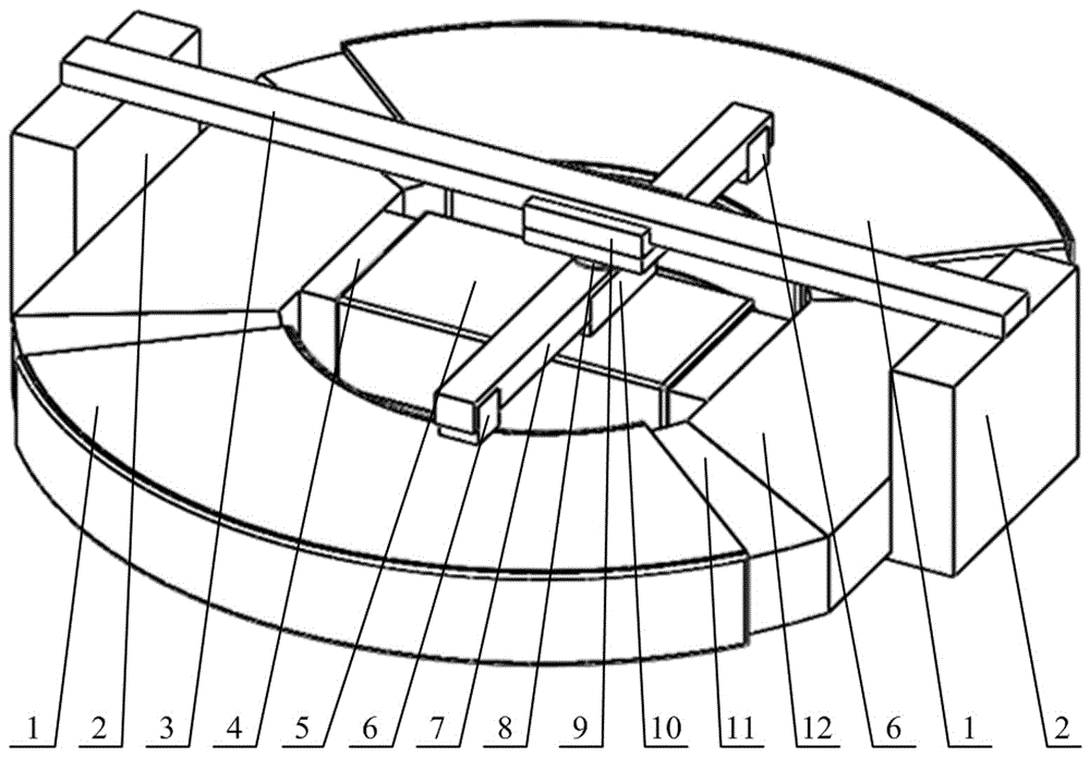
图1给出了直线运动轴线与旋转运动轴线垂直的直线旋转永磁电机三维结构示意图;Figure 1 shows a three-dimensional structural schematic diagram of a linear rotary permanent magnet motor whose linear motion axis is perpendicular to the rotary motion axis;
图2给出了直线旋转永磁电机定子三维结构示意图;Figure 2 shows a three-dimensional schematic diagram of the stator of a linear rotary permanent magnet motor;
图3给出了直线旋转永磁电机定子内侧边线圈及侧边铁芯结构示意图;Fig. 3 shows the structural schematic diagram of the inner side coil and the side iron core of the stator of the linear rotary permanent magnet motor;
图4给出了直线旋转永磁电机定子内中部线圈及中部铁芯结构示意图;Fig. 4 has provided the structural diagram of middle part coil and middle part iron core in the stator of linear rotary permanent magnet motor;
图5给出了直线旋转永磁电机动子三维结构示意图;Figure 5 shows a three-dimensional schematic diagram of the mover of a linear rotary permanent magnet motor;
图6给出了直线旋转永磁电机动子及旋转轴承的三维连接示意图。Figure 6 shows the three-dimensional connection schematic diagram of the linear rotary permanent magnet motor mover and the rotary bearing.
图中:1、侧边线圈;2、滑轨支架;3、直线滑轨;4、中部铁芯;5、中部线圈;6、侧边永磁体;7、动子支架;8、转动轴承;9、直线滑块;10、中部永磁体;11、侧边铁芯;12、连接铁轭;13、运动输出终端。In the figure: 1. Side coil; 2. Slide rail bracket; 3. Linear slide rail; 4. Middle iron core; 5. Middle coil; 6. Side permanent magnet; 7. Mover bracket; 8. Rotary bearing; 9. Linear slider; 10. Permanent magnet in the middle; 11. Side iron core; 12. Connecting iron yoke; 13. Motion output terminal.
具体实施方式Detailed ways
下面将结合本发明实施例中的附图,对本发明实施例中的技术方案进行清楚、完整地描述,显然,所描述的实施例仅仅是本发明一部分实施例,而不是全部的实施例。基于本发明中的实施例,本领域普通技术人员在没有做出创造性劳动前提下所获得的所有其他实施例,都属于本发明保护的范围。The following will clearly and completely describe the technical solutions in the embodiments of the present invention with reference to the accompanying drawings in the embodiments of the present invention. Obviously, the described embodiments are only some, not all, embodiments of the present invention. Based on the embodiments of the present invention, all other embodiments obtained by persons of ordinary skill in the art without making creative efforts belong to the protection scope of the present invention.
在不同附图中以相同标号来标示相同或类似组件;另外请了解文中诸如“第一”、“第二”、“第三”、“上”、“下”、“前”、“后”、“内”、“外”、“端”、“部”、“段”、“宽度”、“厚度”、“区”等等及类似用语仅便于看图者参考图中构造以及仅用于帮助描述本发明而已,并非是对本发明的限定。The same or similar components are marked with the same reference numerals in different drawings; , "inner", "outer", "end", "portion", "section", "width", "thickness", "area", etc. It is only used to help describe the present invention, not to limit the present invention.
请参阅图1-6,本发明提供一种技术方案:一种直线运动轴线与旋转运动轴线垂直的直线旋转永磁电机,该直线旋转永磁电机呈圆盘形,包括定子机构和动子机构,定子机构包括两个侧边线圈1、两个侧边铁芯11、一个中部线圈5、一个中部铁芯4和两个连接铁轭12,侧边线圈1绕设在侧边铁芯11上,两个连接铁轭12和两个侧边铁芯11围成一个环形结构,连接铁轭12与侧边铁芯11交错设置,中部铁芯4连接在两个连接铁轭12之间,中部线圈5绕设在中部铁芯4上;定子机构的结构简单,适用于多维精密运动系统。Please refer to Figures 1-6, the present invention provides a technical solution: a linear rotary permanent magnet motor whose linear motion axis is perpendicular to the rotary motion axis. The linear rotary permanent magnet motor is disc-shaped and includes a stator mechanism and a mover mechanism , the stator mechanism includes two
动子机构包括两块侧边永磁体6、一块中部永磁体10和一个动子支架7,动子支架7活动安装在定子机构的上端,两块侧边永磁体6安装在动子支架7的两端,中部永磁体10安装在动子支架7的中部。动子机构质量轻、运动过程不拖动电缆,动态响应速度快,电机结构简洁。The mover mechanism includes two side
两个连接铁轭12的侧部均连接有滑轨支架2,两个滑轨支架2上连接有直线滑轨3,动子支架7可沿着直线滑轨3滑动。The sides of the two connecting iron yokes 12 are connected with
直线滑轨3的下端安装有直线滑块9,动子支架7通过转动轴承8转动安装在直线滑块9的下端。The lower end of the linear slide rail 3 is provided with a
转动轴承8嵌设在直线滑块9上,转动轴承8的内圈插接有运动输出终端13,运动输出终端13的端部连接在动子支架7上。The
两块侧边永磁体6的尺寸相同,两个侧边线圈1的匝数和结构尺寸均相同。The size of the two side
通过低摩擦的直线滑轨3、直线滑块9以及旋转轴承8以保证直线或旋转运动的顺滑,其中,直线旋转永磁电机利用洛伦兹力驱动电机动子运动。The low-friction linear slide rail 3,
在定子机构和动子机构的配合下,可实现直线运动、旋转运动以及直线旋转运动三种运动方式。与常规直线旋转电机不同,该电机的直线运动轴线与旋转运动轴线垂直,用以满足多维精密复杂运动平台的特殊需求。With the cooperation of the stator mechanism and the mover mechanism, three motion modes of linear motion, rotary motion and linear rotary motion can be realized. Different from conventional linear rotary motors, the linear motion axis of this motor is perpendicular to the rotary motion axis to meet the special needs of multi-dimensional precision and complex motion platforms.
直线运动时,中部线圈5通直流电,根据洛伦兹力原理F=BIL,由于力的作用是相互的,中部永磁体10受到持续的作用力,以生成直线运动。When moving in a straight line, the
两个侧边线圈1可根据实际需求确认通电方向或是否通电,若两个侧边永磁体6充磁方向相同,两个侧边线圈1通入相同方向直流电机,则两个侧边永磁体6受到相同方向电磁力进而生成直线运动;若两个侧边永磁体6充磁方向相反,两个侧边线圈1通入相反方向直流电机,则两个侧边永磁体6受到相同方向电磁力进而生成直线运动;若实际工况对直线推力要求不高,两个侧边线圈1可不通电,由中部线圈5和中部永磁体10提供直线推力。The two
旋转运动时,若需生成单独的旋转运动,中部线圈5不通电,两个侧边线圈1可根据实际需求选择通电方向,若两个侧边永磁体6充磁方向相同,两个侧边线圈1通入相反方向直流电机,则两个侧边永磁体6受到相反方向电磁力进而生成有效的旋转转矩,以产生旋转运动;若两个侧边永磁体6充磁方向相反,两个侧边线圈1通入相同方向直流电机,则两个侧边永磁体6受到相反方向电磁力进而生成有效的旋转转矩。During rotary motion, if a separate rotary motion needs to be generated, the
直线旋转运动时,中部线圈5通直流电,根据根据根据洛伦兹力原理F=BIL,由于力的作用是相互的,中部永磁体10受到持续的作用力,以生成直线运动。During linear rotary motion, the
如两个侧边永磁体6充磁方向相同,两个侧边线圈1通入相反方向直流电机,则两个侧边永磁体受到相反方向电磁力进而生成有效的旋转转矩,以产生旋转运动;若两个侧边永磁体6充磁方向相反,两个侧边线圈1通入相同方向直流电机,则两个侧边永磁体6受到相反方向电磁力进而生成有效的旋转转矩,以产生旋转运动。If the two side
直线旋转运动时,电机解耦控制方便,极大地提高了电机运行中直线运动和旋转运动的精度。During linear rotary motion, the decoupling control of the motor is convenient, which greatly improves the accuracy of linear motion and rotary motion during motor operation.
该直线旋转永磁电机采用精密直线滑轨3和旋转轴承8为电机动子提供支撑,同时也可采用磁浮或气浮方式提供支撑。The linear rotary permanent magnet motor uses precision linear slide rail 3 and
综上所述,本发明与常规直线旋转电机不同,该电机的直线运动轴线与旋转运动轴线垂直,用以满足多维精密复杂运动平台的特殊需求,动子质量轻、运动过程不拖动电缆,动态响应速度快,电机结构简洁,结构简单,适用于多维精密运动系统,电机解耦控制方便,极大地提高了电机运行中直线运动和旋转运动的精度。In summary, the present invention is different from conventional linear rotary motors. The linear motion axis of the motor is perpendicular to the rotary motion axis to meet the special needs of multi-dimensional precision and complex motion platforms. The mover is light in weight and does not drag cables during motion. The dynamic response speed is fast, the motor structure is simple and simple, and it is suitable for multi-dimensional precision motion systems. The decoupling control of the motor is convenient, which greatly improves the accuracy of linear motion and rotary motion during motor operation.
尽管已经示出和描述了本发明的实施例,对于本领域的普通技术人员而言,可以理解在不脱离本发明的原理和精神的情况下可以对这些实施例进行多种变化、修改、替换和变型,本发明的范围由所附权利要求及其等同物限定。Although the embodiments of the present invention have been shown and described, those skilled in the art can understand that various changes, modifications and substitutions can be made to these embodiments without departing from the principle and spirit of the present invention. and modifications, the scope of the invention is defined by the appended claims and their equivalents.
Claims (9)
Priority Applications (1)
| Application Number | Priority Date | Filing Date | Title |
|---|---|---|---|
| CN202211564313.0A CN115580098B (en) | 2022-12-07 | 2022-12-07 | Linear rotation permanent magnet motor with linear motion axis perpendicular to rotation motion axis |
Applications Claiming Priority (1)
| Application Number | Priority Date | Filing Date | Title |
|---|---|---|---|
| CN202211564313.0A CN115580098B (en) | 2022-12-07 | 2022-12-07 | Linear rotation permanent magnet motor with linear motion axis perpendicular to rotation motion axis |
Publications (2)
| Publication Number | Publication Date |
|---|---|
| CN115580098A CN115580098A (en) | 2023-01-06 |
| CN115580098B true CN115580098B (en) | 2023-05-02 |
Family
ID=84589972
Family Applications (1)
| Application Number | Title | Priority Date | Filing Date |
|---|---|---|---|
| CN202211564313.0A Active CN115580098B (en) | 2022-12-07 | 2022-12-07 | Linear rotation permanent magnet motor with linear motion axis perpendicular to rotation motion axis |
Country Status (1)
| Country | Link |
|---|---|
| CN (1) | CN115580098B (en) |
Families Citing this family (1)
| Publication number | Priority date | Publication date | Assignee | Title |
|---|---|---|---|---|
| CN118487458B (en) * | 2024-07-16 | 2024-09-27 | 诸城开元节能科技有限公司 | Multi-working-mode motor |
Family Cites Families (4)
| Publication number | Priority date | Publication date | Assignee | Title |
|---|---|---|---|---|
| CN102946176B (en) * | 2012-12-10 | 2014-12-10 | 山东大学 | Two-degree-of-freedom hybrid stepper motor for bionic eye |
| CN103692960B (en) * | 2013-12-16 | 2016-04-06 | 江苏大学 | A kind of automobile front two-freedom driving and steering system |
| CN205389167U (en) * | 2016-03-08 | 2016-07-20 | 刘照明 | Push type magnetic generator constructs |
| CN111181259B (en) * | 2020-02-20 | 2023-01-10 | 安徽理工大学 | A Linear Rotary Permanent Magnet Motor with E-shaped Stator Structure |
-
2022
- 2022-12-07 CN CN202211564313.0A patent/CN115580098B/en active Active
Also Published As
| Publication number | Publication date |
|---|---|
| CN115580098A (en) | 2023-01-06 |
Similar Documents
| Publication | Publication Date | Title |
|---|---|---|
| CN108809023B (en) | Disc type three-degree-of-freedom magnetic suspension switched reluctance motor | |
| CN102306995B (en) | Permanent magnet biased bearingless switched reluctance motor | |
| CN107134881A (en) | A kind of five degree of freedom composite excitation magnetic suspension switched reluctance motor | |
| WO2019161624A1 (en) | Asymmetric dual three-phase arc permanent magnet synchronous motor | |
| CN114944737B (en) | Primary and secondary mixed excitation type doubly salient two-degree-of-freedom magnetic flux reversing motor | |
| CN102843015A (en) | Linearly-rotating two-degrees-of-freedom magnetic levitation bearing-free permanent magnetic actuator | |
| CN111082551A (en) | Stator and Modular Structure Rotating Linear Two Degrees of Freedom Permanent Magnet Motor | |
| CN108599504B (en) | A five-degree-of-freedom bearingless switched reluctance motor | |
| CN109412370A (en) | Magnetic flux suitching type Linear-rotation permanent-magnet actuator | |
| CN108809024B (en) | An axial single degree of freedom bearingless switched reluctance motor | |
| CN1293319C (en) | Low-consumption permanent-magnet offset external rotor radial magnetic bearing | |
| CN115580098B (en) | Linear rotation permanent magnet motor with linear motion axis perpendicular to rotation motion axis | |
| CN113839516A (en) | Stator module for axial suspension, magnetic suspension motor and linear electromagnetic actuating mechanism | |
| CN110690807B (en) | A cylindrical primary permanent magnet transverse flux linear motor | |
| CN108599505A (en) | A kind of five degrees of freedom without bearing switched reluctance machines | |
| CN1645719A (en) | Permanent magnet electric motor with double rotor | |
| CN102297202B (en) | Single shaft controlled type five-degrees-of-freedom (DOF) miniature magnetic bearing | |
| CN108809021B (en) | A double-sheet five-degree-of-freedom bearingless switched reluctance motor | |
| CN114977705B (en) | Primary and secondary dual permanent magnet two-degree-of-freedom flux reversal motor | |
| CN111030414A (en) | A single-phase cylindrical linear oscillating motor | |
| CN204046380U (en) | A kind of rotational alignment magneto | |
| CN108712048B (en) | Stator permanent magnet type five-degree-of-freedom conical bearingless switched reluctance motor | |
| CN212033981U (en) | Permanent magnet biased quadrupole direct current magnetic suspension linear motor | |
| CN107579639B (en) | High-temperature-resistant permanent magnet servo motor | |
| CN111245195A (en) | A Squirrel-Cage Conductor Rotor Brushless Power Feedback Permanent Magnet Governor |
Legal Events
| Date | Code | Title | Description |
|---|---|---|---|
| PB01 | Publication | ||
| PB01 | Publication | ||
| SE01 | Entry into force of request for substantive examination | ||
| SE01 | Entry into force of request for substantive examination | ||
| GR01 | Patent grant | ||
| GR01 | Patent grant |