CN115576400A - Heat dissipation device with dust removal function for computer hardware - Google Patents
Heat dissipation device with dust removal function for computer hardware Download PDFInfo
- Publication number
- CN115576400A CN115576400A CN202211245010.2A CN202211245010A CN115576400A CN 115576400 A CN115576400 A CN 115576400A CN 202211245010 A CN202211245010 A CN 202211245010A CN 115576400 A CN115576400 A CN 115576400A
- Authority
- CN
- China
- Prior art keywords
- dust
- box
- computer hardware
- rectangular
- pipe
- Prior art date
- Legal status (The legal status is an assumption and is not a legal conclusion. Google has not performed a legal analysis and makes no representation as to the accuracy of the status listed.)
- Withdrawn
Links
- 239000000428 dust Substances 0.000 title claims abstract description 159
- 230000017525 heat dissipation Effects 0.000 title claims abstract description 40
- 238000007664 blowing Methods 0.000 claims abstract description 30
- XLYOFNOQVPJJNP-UHFFFAOYSA-N water Substances O XLYOFNOQVPJJNP-UHFFFAOYSA-N 0.000 claims description 20
- 238000010521 absorption reaction Methods 0.000 claims description 8
- 230000029058 respiratory gaseous exchange Effects 0.000 claims description 6
- 238000000605 extraction Methods 0.000 claims description 4
- 230000001012 protector Effects 0.000 claims description 3
- 230000002146 bilateral effect Effects 0.000 claims description 2
- 230000000694 effects Effects 0.000 abstract description 15
- 238000004140 cleaning Methods 0.000 description 7
- 238000000034 method Methods 0.000 description 3
- 238000013461 design Methods 0.000 description 2
- 238000012423 maintenance Methods 0.000 description 2
- 238000012545 processing Methods 0.000 description 2
- 230000004075 alteration Effects 0.000 description 1
- 230000009286 beneficial effect Effects 0.000 description 1
- 238000001816 cooling Methods 0.000 description 1
- 230000007547 defect Effects 0.000 description 1
- 238000011161 development Methods 0.000 description 1
- 238000012986 modification Methods 0.000 description 1
- 230000004048 modification Effects 0.000 description 1
- 238000006467 substitution reaction Methods 0.000 description 1
- 238000010408 sweeping Methods 0.000 description 1
Images


Classifications
-
- G—PHYSICS
- G06—COMPUTING; CALCULATING OR COUNTING
- G06F—ELECTRIC DIGITAL DATA PROCESSING
- G06F1/00—Details not covered by groups G06F3/00 - G06F13/00 and G06F21/00
- G06F1/16—Constructional details or arrangements
- G06F1/20—Cooling means
-
- B08B1/12—
-
- B08B1/30—
-
- B—PERFORMING OPERATIONS; TRANSPORTING
- B08—CLEANING
- B08B—CLEANING IN GENERAL; PREVENTION OF FOULING IN GENERAL
- B08B15/00—Preventing escape of dirt or fumes from the area where they are produced; Collecting or removing dirt or fumes from that area
- B08B15/04—Preventing escape of dirt or fumes from the area where they are produced; Collecting or removing dirt or fumes from that area from a small area, e.g. a tool
-
- B—PERFORMING OPERATIONS; TRANSPORTING
- B08—CLEANING
- B08B—CLEANING IN GENERAL; PREVENTION OF FOULING IN GENERAL
- B08B5/00—Cleaning by methods involving the use of air flow or gas flow
- B08B5/02—Cleaning by the force of jets, e.g. blowing-out cavities
-
- Y—GENERAL TAGGING OF NEW TECHNOLOGICAL DEVELOPMENTS; GENERAL TAGGING OF CROSS-SECTIONAL TECHNOLOGIES SPANNING OVER SEVERAL SECTIONS OF THE IPC; TECHNICAL SUBJECTS COVERED BY FORMER USPC CROSS-REFERENCE ART COLLECTIONS [XRACs] AND DIGESTS
- Y02—TECHNOLOGIES OR APPLICATIONS FOR MITIGATION OR ADAPTATION AGAINST CLIMATE CHANGE
- Y02D—CLIMATE CHANGE MITIGATION TECHNOLOGIES IN INFORMATION AND COMMUNICATION TECHNOLOGIES [ICT], I.E. INFORMATION AND COMMUNICATION TECHNOLOGIES AIMING AT THE REDUCTION OF THEIR OWN ENERGY USE
- Y02D10/00—Energy efficient computing, e.g. low power processors, power management or thermal management
Abstract
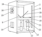
The invention relates to the technical field of dust removal and heat dissipation of computer hardware, and discloses a heat dissipation device with a dust removal function for computer hardware, which comprises a box body, wherein first rectangular holes are correspondingly formed in the left side and the right side of the bottom end of the box body, heat dissipation devices are respectively arranged in the two first rectangular holes, first rectangular grooves are symmetrically formed in the left side and the right side of the top end of the box body, a sliding device, a moving device and a telescopic device are respectively arranged in the box body, a dust cover is arranged on the telescopic device, a cylindrical pipe is fixedly arranged at the center of the bottom end in the dust cover, a dust blowing device is arranged on the cylindrical pipe, a round block is fixedly arranged at one end, far away from the dust cover, of the cylindrical pipe, brushes are uniformly and fixedly arranged on the circumference of the round block, a dust collection device is arranged on the inner wall of the dust cover, dust covered on the outer portion of the computer hardware and dust in the slot are blown away through a first air blowing port and a second air blowing port, the dust collection effect is better under the cooperation of the brushes, and the dust collection efficiency is also improved.
Description
Technical Field
The invention relates to the technical field of computer hardware dust removal and heat dissipation, in particular to a heat dissipation device with a dust removal function for computer hardware.
Background
Computer hardware refers to a general name of various physical devices composed of electronic, mechanical and photoelectric elements and the like in a computer system, along with the rapid development of modern economy, computers are more and more widely used, in the field of computer accessories, a case is used as a part of a host and mainly used for placing and fixing various accessories of the host to play a role in supporting and protecting, a heat dissipation fan is arranged in a common case, the fan can certainly cause air flow when running, dust in the air can enter the case along with the air flow, the heat dissipation device for the computer hardware in the prior art generally has the problem of poor dust removal effect, a computer hardware slot cannot be cleaned, the phenomenon that the dust is attached to the corner of the computer hardware slot and cannot be sucked easily occurs, the heat dissipation efficiency of the hardware is greatly influenced due to the fact that a large amount of dust is covered outside the computer hardware, the computer is blocked, the service life of the hardware is shortened, the heat dissipation effect of the computer hardware is further reduced, the case needs to be opened manually at regular intervals to carry out dust removal, and the dust removal of the case is very difficult due to manual work, so that the dust removal function of the heat dissipation device for the computer hardware is provided.
Disclosure of Invention
Technical problem to be solved
In order to overcome the defects in the prior art, the invention provides a heat dissipation device with a dust removal function for computer hardware, and solves the problems.
(II) technical scheme
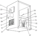
In order to achieve the above purpose, the invention provides the following technical scheme: the utility model provides a heat abstractor that is used for computer hardware to have dust removal function, includes the box, the one end of box is provided with the chamber door, correspond about the bottom of box and seted up first rectangular hole, two first rectangular hole insides all are provided with heat abstractor, and two first rectangular hole outsides all are provided with protector, and first rectangular channel has been seted up to the outside top bilateral symmetry of box, and the inside difference fixed mounting of two first rectangular channels has hair-dryer and dust catcher, both ends correspond the rectangular channel about the inside of box, and the inside of rectangular channel is provided with slider, the last mobile device that is provided with of slider, the last telescoping device that is provided with of mobile device, the top of telescoping device is provided with the shield, and the inside bottom central point of shield puts fixed mounting has the cylinder pipe, is provided with the dust blowing device on the cylinder pipe, and the cylinder pipe is kept away from shield one end fixed mounting and is equipped with the circle piece, and the even fixed mounting in circumference has the brush on the circle piece, be provided with dust extraction on the inner wall of shield, one of the inside correspondence chamber door of box is provided with computer hardware, the bottom fixed mounting of box has the slipmat.
Preferably, first round holes are formed in four corners of the box door, threaded holes are formed in the position, corresponding to the first round holes, of one end of the box body, and the box body and the box door respectively penetrate through the first round holes and are in threaded connection with the threaded holes through four threaded rods.
Preferably, heat abstractor is including heat dissipation fan, first motor and bracing piece, the inside bottom fixed mounting of first rectangular hole has the heat dissipation fan, and the top fixed mounting of heat dissipation fan has first motor, and fixed mounting has the heat dissipation fan on the output of first motor, two heat abstractor mirror images set up.
Preferably, the protection device comprises second round holes, first rectangular frames, cylindrical blocks and blades, the first rectangular frames are fixedly mounted on the outer sides of the first rectangular holes, the second round holes are correspondingly and uniformly formed in the left and right sides of the inside of the first rectangular frames, the blades are arranged between the two corresponding second round holes, the cylindrical blocks are formed in the positions, corresponding to the second round holes, of the two ends of each blade, and the blades are connected with the first rectangular frames in a movable mode through the cylindrical blocks at the two ends in an inserted mode in the corresponding second round holes.
Preferably, the sliding device comprises a sliding block, a movable plate and first electric telescopic rods, the sliding block is arranged in the third rectangular groove in a sliding mode, the movable plate is fixedly arranged between the two sliding blocks, the position, corresponding to the movable plate, of the bottom end in the box body is transversely and uniformly fixedly provided with the two first electric telescopic rods, and the top ends of the two first electric telescopic rods are fixedly connected with the bottom end of the movable plate.
Preferably, the moving device comprises a second rectangular groove, a lead screw, a moving block, a second motor, a first belt pulley, a belt and a second belt pulley, the second rectangular groove is formed in one end wall, away from the box door, of the movable plate, the lead screw is movably mounted inside the second rectangular groove, the ball screw is connected with the moving block on the lead screw, the second belt pulley is welded at one end of the lead screw, a second rectangular hole is formed in the position, corresponding to the second belt pulley, of the top end of the movable plate, the second motor is fixedly mounted at the top end of the movable plate, the first belt pulley is fixedly mounted at the output end of the second motor, the first belt pulley and the second belt pulley are arranged in an up-down corresponding mode, and the first belt pulley is connected with the second belt pulley in a rotating mode through the belt.
Preferably, the telescopic device comprises a dust cover, a second electric telescopic rod is fixedly mounted at the top end of the moving block, and the dust cover is fixedly mounted at one end, far away from the moving block, of the second electric telescopic rod.
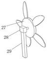
Preferably, blow the dirt device and include first rectangle frame, gas-supply pipe, first mouth and the second mouth of blowing, the output of hair-dryer runs through the one end and the gas-supply pipe grafting fixed connection of box, and the gas-supply pipe runs through shield one end and cylinder pipe fixed connection, keeps away from the slope of shield one end outer wall circumference equidistance on the cylinder pipe and has seted up first mouth of blowing, and first mouth of blowing sets up to brush end slope, and the central point of disk puts and has seted up the second mouth of blowing, the outside fixed mounting of hair-dryer has first rectangle frame, is provided with the filter screen on the first rectangle frame.
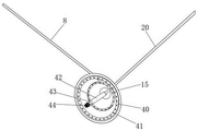
Preferably, dust extraction includes suction cleaner, breathing pipe, ring pipe, dust absorption mouth and recess board, the one end and the breathing pipe grafting fixed connection that the box was run through to the input of suction cleaner are provided with two ring pipes on the shield inner wall, through connecting pipe fixed connection between two ring pipes, evenly seted up the dust absorption mouth respectively on two ring pipes, and the breathing pipe runs through the one end and the connecting pipe fixed connection of shield, the outer wall fixed mounting recess board of suction cleaner.
Preferably, the below fixed mounting water tank of recess board on the box, recess board and water tank pass through L type blast pipe fixed connection, and the drain pipe is installed to the water tank bottom, is provided with the ooff valve on the drain pipe, the inside fixed mounting of box has the fixed plate, and fixed mounting has the battery on the fixed plate, battery and hair-dryer, dust catcher, first motor and second motor electric connection.
(III) advantageous effects
Compared with the prior art, the invention provides a heat dissipation device with a dust removal function for computer hardware, which has the following beneficial effects:
1. this a heat abstractor for computer hardware has dust removal function, through being provided with heat abstractor, the output of first motor is rotatory, can drive the heat dissipation fan and rotate, the heat dissipation fan rotates and dispels the heat to the box is inside, the rethread is provided with protector, when not needing the heat dissipation, manual promotion blade rotates, make the blade rotate to erecting the vertical position, a plurality of blades can form a guard plate, prevent that the dust from getting into the box through two first rectangular holes in, moreover, the steam generator is simple in structure, and reasonable design, has fine dustproof effect, the frequency of artifical deashing has effectively been reduced, and the cost is saved.
2. This a heat abstractor that is used for computer hardware to have dust removal function, through being provided with slider, two first electric telescopic handle simultaneous telescopic movement, can make two sliders reciprocate respectively in two third rectangular channels insidely, thereby drive the fly leaf, second electric telescopic handle and brush reciprocate, make things convenient for the brush to reciprocate and clean adhering to the outside dust of computer hardware and the inside dust of computer hardware slot, through being provided with mobile device, the output of second motor is rotatory, can drive first belt pulley rotation, first belt pulley rotation drives the second belt pulley rotation through the belt, can make the rotatory movable block that drives of lead screw remove about, thereby make second electric telescopic handle, the shield, cylinder pipe and brush remove about, make things convenient for the brush to carry out the cleaning at full aspect no dead angle to the dust of computer hardware and slot inside, the effectual dust removal effect to computer hardware that has improved.
3. This a heat abstractor for computer hardware has dust removal function, blow the dirt device through being provided with, the hair-dryer is inside with gaseous through the gas-supply pipe transport cylinder, the first mouth of blowing of rethread and the second mouth of blowing blow the cover at the outside dust of computer hardware and the inside dust of computer hardware slot, it makes the clearance effect to the dust better to lie in under the cooperation of brush, improve the cleaning efficiency to the dust in the slot simultaneously greatly, through being provided with dust extraction, the dust absorption mouth has evenly been seted up on two annular pipes of the inner wall setting of shield respectively, when blowing the outside dust of slot inner wall and computer hardware, the inside dust absorption mouth of shield will absorb the dust that cleans the in-process and produce, avoid the dust to diffuse inside the box, and collect the dust through the water tank, cleaning efficiency has not only been improved, and make things convenient for people to clear up the dust.
4. This a heat abstractor for computer hardware has dust removal function, through being provided with the water tank, after the water tank inside interpolation is less than water, can carry the gas that adsorbs the dust to the aquatic through L type blast pipe, make water adsorb the dust, avoid scattering of dust, do benefit to the processing to the dust, increaseed the protection to the environment simultaneously.
Drawings
FIG. 1 is a schematic structural view of the present invention;
FIG. 2 is a perspective view of the door of the present invention;
FIG. 3 is a left side perspective view of the housing of the present invention;
FIG. 4 is a right side perspective view of the housing of the present invention;
FIG. 5 is a bottom perspective view of the container body of the present invention;
FIG. 6 is a perspective view of a heat dissipation fan according to the present invention;
FIG. 7 is a perspective view of a first rectangular frame of the present invention;
FIG. 8 is a perspective view of the movable plate of the present invention;
FIG. 9 is a perspective view of the dust cap of the present invention;
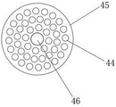
FIG. 10 is a schematic plan view of a round block of the present invention;
FIG. 11 is a schematic plan view of a cylindrical tube according to the present invention.
In the figure: 1. a box body; 2. a box door; 3. a threaded rod; 4. a first rectangular frame; 5. a first rectangular frame; 6. a blade; 7. a first circular hole; 8. an air intake duct; 9. a third rectangular groove; 10. a slider; 11. a movable plate; 12. a first electric telescopic rod; 13. a threaded hole; 14. a first rectangular hole; 15. a dust cover; 16. a first rectangular groove; 17. a blower; 18. computer hardware; 19. a dust collector; 20. a gas delivery pipe; 21. a storage battery 22 and a fixing plate; 23. a groove plate; 24. an L-shaped exhaust pipe; 25. a water tank; 26; a drain pipe; 27. a heat dissipation fan; 28. a first motor; 29. a support bar; 30. a second circular hole; 31. a cylindrical block; 32. a second rectangular groove; 33. a lead screw; 34. a moving block; 35. a second electric telescopic rod; 36. a second motor; 37. a first pulley, 38, a belt; 39. a second pulley; 40. an annular tube; 41. a dust suction port; 42. a cylindrical tube; 43. a first blowing port; 44. a brush; 45. a round block; 46. a second air blowing port; 47. a second rectangular aperture.
Detailed Description
The technical solutions in the embodiments of the present invention will be clearly and completely described below with reference to the drawings in the embodiments of the present invention, and it is obvious that the described embodiments are only a part of the embodiments of the present invention, and not all of the embodiments. All other embodiments, which can be obtained by a person skilled in the art without making any creative effort based on the embodiments in the present invention, belong to the protection scope of the present invention.
Referring to fig. 1-11, a heat dissipation device with a dust removal function for computer hardware includes a box 1, a box door 2 is disposed at one end of the box 1, first rectangular holes 14 are correspondingly formed in the left and right sides of the bottom end of the box 1, heat dissipation devices are disposed inside the two first rectangular holes 14, protection devices are disposed outside the two first rectangular holes 14, first rectangular grooves 16 are symmetrically formed in the left and right sides of the top end of the box 1, a blower 17 and a dust collector 19 are respectively and fixedly mounted inside the two first rectangular grooves 16, rectangular grooves 9 are respectively formed in the left and right sides of the inside of the box 1, sliding devices are disposed inside the rectangular grooves 9, moving devices are disposed on the sliding devices, telescopic devices are disposed on the moving devices, a dust cover 15 is disposed at the top end of the telescopic devices, a cylindrical pipe 42 is fixedly mounted at the center position of the bottom end of the dust cover 15, a dust blowing device is disposed on the cylindrical pipe 42, a round block 45 is fixedly mounted at one end of the cylindrical pipe 42 far away from the dust cover 15, brushes 44 are circumferentially and fixedly mounted on the inner wall of the dust cover 15, a bottom end of the box 1 corresponding to the hardware is disposed with an anti-slip pad 18.
Further, first round hole 7 has been seted up to four corners on chamber door 2, and threaded hole 13 has all been seted up to the position that one end corresponds first round hole 7 on the box 1, and box 1 passes first round hole 7 and threaded hole 13 threaded connection respectively through four threaded rods 3 with chamber door 2, demolishs box 1 and chamber door 2 through rotating threaded rod 3, the maintenance and the maintenance work in the later stage of being convenient for.
Further, heat abstractor includes heat dissipation fan 27, first motor 28 and bracing piece 29, the inside bottom fixed mounting of first rectangular hole 14 has heat dissipation fan 27, the top fixed mounting of heat dissipation fan 27 has first motor 28, fixed mounting has heat dissipation fan 27 on the output of first motor 28, two heat abstractor mirror image settings, the output of first motor 28 is rotatory, first motor 28 is micro motor, can drive heat dissipation fan 27 and rotate, heat dissipation fan 27 rotates and dispels the heat the cooling to box 1 inside.
Further, the protection device comprises second round holes 30, first rectangular frames 5, cylindrical blocks 31 and blades 6, first rectangular frames 5 are fixedly mounted on the outer sides of the first rectangular holes 14, second round holes 30 are correspondingly and uniformly formed in the left and right sides of the inside of the first rectangular frames 5, the blades 6 are arranged between the two corresponding second round holes 30, the cylindrical blocks 31 are arranged at the two ends of each blade 6 corresponding to the positions of the corresponding second round holes 30, the blades 6 are connected with the first rectangular frames 5 in a movable mode through the cylindrical blocks 31 at the two ends in an inserting mode inside the corresponding second round holes 30, the connecting between the second round holes 30 and the cylindrical blocks 31 is tight, the blades 6 need to be pushed to rotate only with manual force, when heat dissipation is not needed, the blades 6 are manually pushed to rotate, the blades 6 are rotated to be erected at the vertical positions, a protection plate can be formed by the plurality of blades 6, dust is prevented from entering the box body 1 through the two first rectangular holes 14, the structure is simple, the dust removal device is reasonable in design, the dust removal effect is good in dust removal effect, the effect is effectively reduced, and the labor frequency is saved in cost.
Further, the slider includes slider 10, fly leaf 11 and first electric telescopic handle 12, the equal slidable mounting in inside of two third rectangular channels 9 has slider 10, fixed mounting has fly leaf 11 between two sliders 10, the horizontal even fixed mounting in position that the inside bottom of box 1 corresponds fly leaf 11 has two first electric telescopic handle 12, the top of two first electric telescopic handle 12 all with fly leaf 11 bottom fixed connection, two first electric telescopic handle 12 stretch out and draw back simultaneously and move, can make two sliders 10 reciprocate respectively in two third rectangular channels 9 insides, thereby drive fly leaf 11, second electric telescopic handle 35 and brush 44 reciprocate, make things convenient for brush 44 to reciprocate and clean attaching to the outside dust of computer hardware and the inside dust of computer hardware slot.
Further, the moving device includes a second rectangular groove 32, a lead screw 33, a moving block 34, a second motor 36, a first belt pulley 37, a belt 38 and a second belt pulley 39, the second rectangular groove 32 is formed in an end wall, away from the door 2, of the movable plate 11, the lead screw 33 is movably mounted inside the second rectangular groove 32, the ball screw is connected to the lead screw 33, the second belt pulley 39 is welded to one end of the lead screw 33, a second rectangular hole 47 is formed in a position, corresponding to the second belt pulley 39, of the top end of the movable plate 11, the second motor 36 is fixedly mounted at the top end of the movable plate 11, a first belt pulley 37 is fixedly mounted at an output end of the second motor 36, the first belt pulley 37 and the second belt pulley 39 are vertically and correspondingly arranged, the first belt pulley 37 and the second belt pulley 39 are rotatably connected through the belt 38, the output end of the second motor 36 rotates to drive the first belt pulley 37 to rotate, the first belt pulley 37 rotates to drive the second belt pulley 39 to rotate, the lead screw 33 to drive the moving block 34 to move left and right, so that the second electric telescopic rod 35, the dust cover 15, the cylindrical tube 42 and the brush 44 and the dust removing hardware are effective to improve the dust removing effect of the dust removing machine.
Further, the telescoping device includes shield 15, and movable block 34 top fixed mounting has second electric telescopic handle 35, and second electric telescopic handle 35 keeps away from movable block 34 one end fixed mounting and has shield 15, and second electric telescopic handle 35 is convenient for take brush 44 to carry out the back-and-forth movement, is convenient for adjust the front and back position of brush 44, makes things convenient for brush 44 to carry out the sweeping at full aspect no dead angle to the inside dust of computer hardware and slot.
Furthermore, the dust blowing device comprises a first rectangular frame 4, an air pipe 20, a first air blowing port 43 and a second air blowing port 46, wherein the output end of the blower 17 penetrates one end of the box body 1 to be fixedly connected with the air pipe 20 in an inserted manner, the air pipe 20 penetrates one end of the dust cover 15 to be fixedly connected with the cylindrical pipe 42, the first air blowing port 43 is obliquely arranged on the outer wall of the cylindrical pipe 42 at the end far away from the dust cover 15 at an equal circumferential distance, the first air blowing port 43 is obliquely arranged towards the end of the hairbrush 44, the second air blowing port 46 is arranged at the central position of the round block 45, the outside fixed mounting of hair-dryer 17 has first rectangle frame 4, be provided with the filter screen on the first rectangle frame 4, inside hair-dryer 16 carried cylinder pipe 42 with gas through gas-supply pipe 20, the first mouth 43 of blowing of rethread and second mouth 46 of blowing blow off covering at the outside dust of computer hardware and the inside dust of computer hardware slot, it makes the clearance effect to the dust better to lie in under the cooperation of brush 44, improve the clearance efficiency to the dust in the slot simultaneously greatly.
Further, the dust suction device comprises a dust collector 19, an air suction pipe 8, annular pipes 40, dust suction openings 41 and groove plates 23, the input end of the dust collector 19 penetrates through one end of the box body 1 and is fixedly connected with the air suction pipe 8 in an inserting mode, two annular pipes 40 are arranged on the inner wall of the dust cover 15, the two annular pipes 40 are fixedly connected through a connecting pipe, the dust suction openings 41 are uniformly formed in the two annular pipes 40 respectively, the air suction pipe 8 penetrates through one end of the dust cover 15 and is fixedly connected with the connecting pipe, the groove plates 23 are fixedly installed on the outer wall of the dust collector 19, the air suction pipe 8 and the air conveying pipe 20 are flexible pipes capable of extending and contracting, the two annular pipes 40 are the same in shape and different in proportion, the dust suction openings 41 are uniformly formed in the two annular pipes 40 arranged on the inner wall of the dust cover 15 respectively, when dust outside the inner wall of the slot and the computer hardware is blown away, the dust suction openings 41 inside the dust cover 15 can absorb dust generated in the cleaning process, the dust is prevented from diffusing inside the box body 1, the dust is collected through the water tank 25, the cleaning efficiency is improved, and convenience is brought for people to clean the dust.
Further, recess board 23's below fixed mounting water tank 25 on box 1, recess board 23 passes through L type blast pipe 24 fixed connection with water tank 25, drain pipe 26 is installed to water tank 25 bottom, be provided with ooff valve on the drain pipe 26, the inside fixed mounting of box 1 has fixed plate 22, fixed mounting has battery 21 on the fixed plate 22, battery 21 and hair-dryer 17, dust catcher 19, first motor 28 and the 36 electric connection of second motor, after water tank 25 inside interpolation is less than water, can pass through L type blast pipe 24 with the gas that adsorbs the dust and carry to aquatic, make water adsorb the dust, avoid scattering of dust, do benefit to the processing to the dust, the protection to the environment has been increaseed simultaneously.
Working principle; when the device is used, computer hardware is arranged on the end wall of the box body 1 corresponding to the box door 2, when the computer works, the output end of the first motor 28 rotates to drive the heat dissipation fan 27 to rotate, the heat dissipation fan 27 rotates to dissipate heat and cool the interior of the box body 1, when the computer does not work, the blades 6 are manually pushed to rotate to enable the blades 6 to rotate to be vertical, the blades 6 form a protection plate to prevent dust from entering the box body 1 through the two first rectangular holes 14, the dust-proof effect is good, the frequency of manual dust cleaning is effectively reduced, the two first electric telescopic rods 12 simultaneously extend and retract, the two sliding blocks 10 can respectively move up and down in the two third rectangular grooves 9 by arranging the sliding device, so as to drive the movable plate 11, the second electric telescopic rods 35 and the brush telescopic rods 44 to move up and down, the brush 44 can move up and down conveniently to clean dust attached to the outside of the computer hardware and dust inside the slot of the computer hardware, the output end of the second motor 36 rotates through the moving device to drive the first belt pulley 37 to rotate, the first belt pulley 37 rotates to drive the second belt pulley 39 to rotate through the belt 38, the lead screw 33 can rotate to drive the moving block 34 to move left and right, so that the second electric telescopic rod 35, the dust cover 15, the cylindrical pipe 42 and the brush 44 can move left and right, the dust removal effect on the computer hardware is effectively improved, the second electric telescopic rod 35 can conveniently drive the brush 44 to move back and forth through the telescopic device, the front and back position of the brush 44 can be conveniently adjusted, the brush 44 can conveniently clean the computer hardware and the dust inside the slot in an all-around dead angle-free manner, and then the dust blowing device and the dust suction device are arranged, inside cylinder 42 is carried with gas through gas-supply pipe 20 to hair-dryer 16, the inside dust of rethread first mouth 43 of blowing and second mouth 46 of blowing blows away at the outside dust of computer hardware and the inside dust of computer hardware slot, it makes the clearance effect to the dust better to lie in under the cooperation of brush 44, improve the clearance efficiency to the dust in the slot simultaneously greatly, dust absorption mouth 41 has evenly been seted up on two annular pipes 40 of the inner wall setting of shield 15 respectively, when blowing away at slot inner wall and the outside dust of computer hardware, the inside dust absorption mouth 41 of shield 15 will absorb the dust that the in-process produced of cleaning, avoid the dust to diffuse inside box 1, and collect the dust through water tank 25, not only improve clean efficiency, and make things convenient for people to clear up the dust.
Although embodiments of the present invention have been shown and described, it will be appreciated by those skilled in the art that various changes, modifications, substitutions and alterations can be made in these embodiments without departing from the principles and spirit of the invention, the scope of which is defined in the appended claims and their equivalents.
Claims (10)
1. The utility model provides a heat abstractor that is used for computer hardware to have dust removal function, includes box (1), its characterized in that: the utility model discloses a dustproof computer box, including box (1), dust catcher, dust cover (15), dust catcher, protection device, rectangular groove (9), slider, dust pan (42), dust pan (15) and fan, the one end of box (1) is provided with chamber door (2), first rectangular hole (14) have been seted up to the correspondence about the bottom of box (1), and two inside all are provided with heat abstractor in first rectangular hole (14), and two first rectangular hole (14) outsides all are provided with protector, and first rectangular groove (16) have been seted up to the top bilateral symmetry in the box (1) outside, and the inside difference fixed mounting of two first rectangular grooves (16) has hair-dryer (17) and dust catcher (19), both ends correspond rectangular groove (9) about the inside of box (1), and the inside of rectangular groove (9) is provided with slider, is provided with the mobile device on the slider, is provided with the telescoping device on the mobile device, and the top of telescoping device is provided with dust cover (15), and the inside bottom central point fixed mounting of dust cover (15) has cylinder pipe (42), is provided with round piece (45) on cylinder pipe (42), and the even fixed mounting in circumference has round piece (44) on round piece (45), be provided with dust catcher (15) on the inner wall of dust catcher (1) the hardware the one end of box (18) the corresponding on the calculation box (1).
2. The heat sink with dust removing function for computer hardware as claimed in claim 1, wherein: first round hole (7) have been seted up to four corners on chamber door (2), and threaded hole (13) are all seted up to the position that one end corresponds first round hole (7) on box (1), and box (1) and chamber door (2) pass first round hole (7) and threaded hole (13) threaded connection respectively through four threaded rods (3).
3. The heat sink with dust removing function for computer hardware as claimed in claim 1, wherein: the heat dissipation device comprises a heat dissipation fan (27), a first motor (28) and a support rod (29), wherein the heat dissipation fan (27) is fixedly installed at the bottom end of the first rectangular hole (14), the top end of the heat dissipation fan (27) is fixedly installed with the first motor (28), the heat dissipation fan (27) is fixedly installed at the output end of the first motor (28), and the two heat dissipation device mirror images are arranged.
4. The heat sink with dust removal function for computer hardware according to claim 1, wherein: the protection device comprises a second round hole (30), a first rectangular frame (5), a cylindrical block (31) and blades (6), wherein the first rectangular frame (5) is fixedly arranged on the outer side of the first rectangular hole (14), the second round hole (30) is uniformly formed in the first rectangular frame (5) in a left-right corresponding mode, the blades (6) are arranged between the two corresponding second round holes (30), the cylindrical block (31) is formed in the positions, corresponding to the second round holes (30), of the two ends of each blade (6), and the blades (6) are connected with the first rectangular frame (5) in a movable mode in the corresponding second round holes (30) in a splicing mode through the cylindrical blocks (31) at the two ends.
5. The heat sink with dust removing function for computer hardware as claimed in claim 1, wherein: the sliding device comprises a sliding block (10), a movable plate (11) and first electric telescopic rods (12), the sliding block (10) is arranged in the third rectangular groove (9) in a sliding mode, the movable plate (11) is fixedly arranged between the two sliding blocks (10), the two first electric telescopic rods (12) are transversely and uniformly fixedly arranged at positions, corresponding to the movable plate (11), of the bottom end of the inner portion of the box body (1), and the top ends of the two first electric telescopic rods (12) are fixedly connected with the bottom end of the movable plate (11).
6. The heat sink with dust removing function for computer hardware as claimed in claim 5, wherein: the moving device comprises a second rectangular groove (32), a lead screw (33), a moving block (34), a second motor (36), a first belt pulley (37), a belt (38) and a second belt pulley (39), the second rectangular groove (32) is formed in one end wall, away from the box door (2), of the moving plate (11), the lead screw (33) is movably mounted inside the second rectangular groove (32), the ball lead screw is connected with the moving block (34) on the lead screw (33), the second belt pulley (39) is welded at one end of the lead screw (33), a second rectangular hole (47) is formed in the position, corresponding to the second belt pulley (39), of the top end of the moving plate (11), the second motor (36) is fixedly mounted at the top end of the moving plate (11), the first belt pulley (37) is fixedly mounted at the output end of the second motor (36), the first belt pulley (37) and the second belt pulley (39) are arranged in an up-down corresponding mode, and the first belt pulley (37) and the second belt pulley (39) are connected in a rotating mode through the belt (38).
7. The heat sink with dust removal function for computer hardware according to claim 6, wherein: the telescopic device comprises a dustproof cover (15), a second electric telescopic rod (35) is fixedly mounted at the top end of the moving block (34), and the dustproof cover (15) is fixedly mounted at one end, far away from the moving block (34), of the second electric telescopic rod (35).
8. The heat sink with dust removing function for computer hardware as claimed in claim 1, wherein: blow the dirt device and include first rectangle frame (4), gas-supply pipe (20), first mouth (43) and the second mouth (46) of blowing, the output of hair-dryer (17) runs through the one end and the gas-supply pipe (20) grafting fixed connection of box (1), and gas-supply pipe (20) run through shield (15) one end and cylinder pipe (42) fixed connection, and it has seted up first mouth (43) of blowing to keep away from the equidistance slope of shield (15) one end outer wall circumference on cylinder pipe (42), and first mouth (43) of blowing set up to brush (44) end slope, and the central point of circle piece (45) puts and has seted up second mouth (46) of blowing, the outside fixed mounting of hair-dryer (17) has first rectangle frame (4), is provided with the filter screen on first rectangle frame (4).
9. The heat sink with dust removing function for computer hardware as claimed in claim 1, wherein: dust extraction includes dust catcher (19), breathing pipe (8), ring duct (40), dust absorption mouth (41) and recess board (23), the one end that the input of dust catcher (19) runs through box (1) is pegged graft fixed connection with breathing pipe (8), is provided with two ring ducts (40) on shield (15) inner wall, through connecting pipe fixed connection between two ring ducts (40), evenly has seted up dust absorption mouth (41) respectively on two ring ducts (40), one end and connecting pipe fixed connection that breathing pipe (8) run through shield (15), the outer wall fixed mounting recess board (23) of dust catcher (19).
10. The heat sink with dust removing function for computer hardware according to claim 9, wherein: below fixed mounting water tank (25) of recess board (23) on box (1), recess board (23) pass through L type blast pipe (24) fixed connection with water tank (25), and drain pipe (26) are installed to water tank (25) bottom, are provided with ooff valve on drain pipe (26), box (1) inside fixed mounting has fixed plate (22), and fixed mounting has battery (21) on fixed plate (22), battery (21) and hair-dryer (17), dust catcher (19), first motor (28) and second motor (36) electric connection.
Priority Applications (1)
| Application Number | Priority Date | Filing Date | Title |
|---|---|---|---|
| CN202211245010.2A CN115576400A (en) | 2022-10-12 | 2022-10-12 | Heat dissipation device with dust removal function for computer hardware |
Applications Claiming Priority (1)
| Application Number | Priority Date | Filing Date | Title |
|---|---|---|---|
| CN202211245010.2A CN115576400A (en) | 2022-10-12 | 2022-10-12 | Heat dissipation device with dust removal function for computer hardware |
Publications (1)
| Publication Number | Publication Date |
|---|---|
| CN115576400A true CN115576400A (en) | 2023-01-06 |
Family
ID=84585377
Family Applications (1)
| Application Number | Title | Priority Date | Filing Date |
|---|---|---|---|
| CN202211245010.2A Withdrawn CN115576400A (en) | 2022-10-12 | 2022-10-12 | Heat dissipation device with dust removal function for computer hardware |
Country Status (1)
| Country | Link |
|---|---|
| CN (1) | CN115576400A (en) |
Cited By (2)
| Publication number | Priority date | Publication date | Assignee | Title |
|---|---|---|---|---|
| CN117277114A (en) * | 2023-11-17 | 2023-12-22 | 哈尔滨金融学院 | Self-cleaning type electric control box |
| CN117336984A (en) * | 2023-12-01 | 2024-01-02 | 江苏精一电气科技有限公司 | Prefabricated intelligent equipment cabinet |
-
2022
- 2022-10-12 CN CN202211245010.2A patent/CN115576400A/en not_active Withdrawn
Cited By (4)
| Publication number | Priority date | Publication date | Assignee | Title |
|---|---|---|---|---|
| CN117277114A (en) * | 2023-11-17 | 2023-12-22 | 哈尔滨金融学院 | Self-cleaning type electric control box |
| CN117277114B (en) * | 2023-11-17 | 2024-02-02 | 哈尔滨金融学院 | Self-cleaning type electric control box |
| CN117336984A (en) * | 2023-12-01 | 2024-01-02 | 江苏精一电气科技有限公司 | Prefabricated intelligent equipment cabinet |
| CN117336984B (en) * | 2023-12-01 | 2024-03-08 | 江苏精一电气科技有限公司 | Prefabricated intelligent equipment cabinet |
Similar Documents
| Publication | Publication Date | Title |
|---|---|---|
| CN115576400A (en) | Heat dissipation device with dust removal function for computer hardware | |
| CN208674643U (en) | High-low pressure reactive compensation electric power cabinet with dedusting function | |
| CN208586391U (en) | A kind of dust exhaust apparatus of weaving loom | |
| CN113275320A (en) | Computer convenient to remove dust | |
| CN205950466U (en) | Dustless grinding device is used to cast iron | |
| CN210253237U (en) | Surface dust removal device for electric power cabinet | |
| CN212462375U (en) | Portable security protection switch board | |
| CN215996019U (en) | Air-exhaust back-blowing type dust treatment equipment | |
| CN212069866U (en) | Dust protected full-automatic gauze mask machine | |
| CN215339767U (en) | Atmosphere detection equipment with automatic dust cleaning function | |
| CN212991632U (en) | Dustproof electric power cabinet of electric power | |
| CN212790150U (en) | Workshop dust shaker with automatically cleaning | |
| CN212262753U (en) | Cooling and dust removing device for coal mine machine | |
| CN209424194U (en) | A kind of electrical equipment dust-extraction unit | |
| CN210104155U (en) | Two-for-one twisting equipment for tufted carpet production | |
| CN113834157B (en) | Dust-proof ventilation filter device for railway track engineering | |
| CN219536717U (en) | Dust filtering and ventilating equipment for communication base station room | |
| CN217411728U (en) | Dustproof device for mesh cabinet | |
| CN110918526A (en) | Cleaning device for power transmission line | |
| CN219076161U (en) | Dust removing device | |
| CN211633106U (en) | Rotary filter screen device of sweeping robot | |
| CN216026746U (en) | Dust collector for electric power system secondary protection | |
| CN218608524U (en) | Dust collector is used in knitted fabric production | |
| CN213855289U (en) | Communication mainframe box powder spraying device | |
| CN220123245U (en) | Dustproof electric cabinet |
Legal Events
| Date | Code | Title | Description |
|---|---|---|---|
| PB01 | Publication | ||
| PB01 | Publication | ||
| SE01 | Entry into force of request for substantive examination | ||
| SE01 | Entry into force of request for substantive examination | ||
| WW01 | Invention patent application withdrawn after publication |
Application publication date: 20230106 |
|
| WW01 | Invention patent application withdrawn after publication |