CN115570963A - Electric automobile of direct assembly electricity core - Google Patents
Electric automobile of direct assembly electricity core Download PDFInfo
- Publication number
- CN115570963A CN115570963A CN202211299491.5A CN202211299491A CN115570963A CN 115570963 A CN115570963 A CN 115570963A CN 202211299491 A CN202211299491 A CN 202211299491A CN 115570963 A CN115570963 A CN 115570963A
- Authority
- CN
- China
- Prior art keywords
- battery
- vehicle body
- module group
- floor
- battery module
- Prior art date
- Legal status (The legal status is an assumption and is not a legal conclusion. Google has not performed a legal analysis and makes no representation as to the accuracy of the status listed.)
- Pending
Links
Images


Classifications
-
- B—PERFORMING OPERATIONS; TRANSPORTING
- B60—VEHICLES IN GENERAL
- B60K—ARRANGEMENT OR MOUNTING OF PROPULSION UNITS OR OF TRANSMISSIONS IN VEHICLES; ARRANGEMENT OR MOUNTING OF PLURAL DIVERSE PRIME-MOVERS IN VEHICLES; AUXILIARY DRIVES FOR VEHICLES; INSTRUMENTATION OR DASHBOARDS FOR VEHICLES; ARRANGEMENTS IN CONNECTION WITH COOLING, AIR INTAKE, GAS EXHAUST OR FUEL SUPPLY OF PROPULSION UNITS IN VEHICLES
- B60K1/00—Arrangement or mounting of electrical propulsion units
- B60K1/04—Arrangement or mounting of electrical propulsion units of the electric storage means for propulsion
-
- B—PERFORMING OPERATIONS; TRANSPORTING
- B60—VEHICLES IN GENERAL
- B60L—PROPULSION OF ELECTRICALLY-PROPELLED VEHICLES; SUPPLYING ELECTRIC POWER FOR AUXILIARY EQUIPMENT OF ELECTRICALLY-PROPELLED VEHICLES; ELECTRODYNAMIC BRAKE SYSTEMS FOR VEHICLES IN GENERAL; MAGNETIC SUSPENSION OR LEVITATION FOR VEHICLES; MONITORING OPERATING VARIABLES OF ELECTRICALLY-PROPELLED VEHICLES; ELECTRIC SAFETY DEVICES FOR ELECTRICALLY-PROPELLED VEHICLES
- B60L58/00—Methods or circuit arrangements for monitoring or controlling batteries or fuel cells, specially adapted for electric vehicles
- B60L58/10—Methods or circuit arrangements for monitoring or controlling batteries or fuel cells, specially adapted for electric vehicles for monitoring or controlling batteries
- B60L58/24—Methods or circuit arrangements for monitoring or controlling batteries or fuel cells, specially adapted for electric vehicles for monitoring or controlling batteries for controlling the temperature of batteries
- B60L58/26—Methods or circuit arrangements for monitoring or controlling batteries or fuel cells, specially adapted for electric vehicles for monitoring or controlling batteries for controlling the temperature of batteries by cooling
-
- B—PERFORMING OPERATIONS; TRANSPORTING
- B60—VEHICLES IN GENERAL
- B60N—SEATS SPECIALLY ADAPTED FOR VEHICLES; VEHICLE PASSENGER ACCOMMODATION NOT OTHERWISE PROVIDED FOR
- B60N2/00—Seats specially adapted for vehicles; Arrangement or mounting of seats in vehicles
- B60N2/005—Arrangement or mounting of seats in vehicles, e.g. dismountable auxiliary seats
- B60N2/015—Attaching seats directly to vehicle chassis
-
- B—PERFORMING OPERATIONS; TRANSPORTING
- B60—VEHICLES IN GENERAL
- B60T—VEHICLE BRAKE CONTROL SYSTEMS OR PARTS THEREOF; BRAKE CONTROL SYSTEMS OR PARTS THEREOF, IN GENERAL; ARRANGEMENT OF BRAKING ELEMENTS ON VEHICLES IN GENERAL; PORTABLE DEVICES FOR PREVENTING UNWANTED MOVEMENT OF VEHICLES; VEHICLE MODIFICATIONS TO FACILITATE COOLING OF BRAKES
- B60T17/00—Component parts, details, or accessories of power brake systems not covered by groups B60T8/00, B60T13/00 or B60T15/00, or presenting other characteristic features
- B60T17/04—Arrangements of piping, valves in the piping, e.g. cut-off valves, couplings or air hoses
-
- B—PERFORMING OPERATIONS; TRANSPORTING
- B60—VEHICLES IN GENERAL
- B60K—ARRANGEMENT OR MOUNTING OF PROPULSION UNITS OR OF TRANSMISSIONS IN VEHICLES; ARRANGEMENT OR MOUNTING OF PLURAL DIVERSE PRIME-MOVERS IN VEHICLES; AUXILIARY DRIVES FOR VEHICLES; INSTRUMENTATION OR DASHBOARDS FOR VEHICLES; ARRANGEMENTS IN CONNECTION WITH COOLING, AIR INTAKE, GAS EXHAUST OR FUEL SUPPLY OF PROPULSION UNITS IN VEHICLES
- B60K1/00—Arrangement or mounting of electrical propulsion units
- B60K1/04—Arrangement or mounting of electrical propulsion units of the electric storage means for propulsion
- B60K2001/0405—Arrangement or mounting of electrical propulsion units of the electric storage means for propulsion characterised by their position
- B60K2001/0438—Arrangement under the floor
-
- Y—GENERAL TAGGING OF NEW TECHNOLOGICAL DEVELOPMENTS; GENERAL TAGGING OF CROSS-SECTIONAL TECHNOLOGIES SPANNING OVER SEVERAL SECTIONS OF THE IPC; TECHNICAL SUBJECTS COVERED BY FORMER USPC CROSS-REFERENCE ART COLLECTIONS [XRACs] AND DIGESTS
- Y02—TECHNOLOGIES OR APPLICATIONS FOR MITIGATION OR ADAPTATION AGAINST CLIMATE CHANGE
- Y02E—REDUCTION OF GREENHOUSE GAS [GHG] EMISSIONS, RELATED TO ENERGY GENERATION, TRANSMISSION OR DISTRIBUTION
- Y02E60/00—Enabling technologies; Technologies with a potential or indirect contribution to GHG emissions mitigation
- Y02E60/10—Energy storage using batteries
Landscapes
- Engineering & Computer Science (AREA)
- Transportation (AREA)
- Mechanical Engineering (AREA)
- Chemical & Material Sciences (AREA)
- Combustion & Propulsion (AREA)
- Life Sciences & Earth Sciences (AREA)
- Sustainable Development (AREA)
- Sustainable Energy (AREA)
- Power Engineering (AREA)
- Aviation & Aerospace Engineering (AREA)
- Arrangement Or Mounting Of Propulsion Units For Vehicles (AREA)
Abstract
The invention provides an electric automobile with a directly assembled battery cell, which comprises: the battery module group is used for assembling a lower vehicle body and comprises a battery frame, and a battery core and a high-voltage accessory which are arranged in the battery frame; the upper vehicle body is arranged on the battery module group; the torsion box is arranged on the battery module group; the battery frame is characterized in that the joints of the two sides of the battery frame and the upper vehicle body are of multilayer ladder-shaped structures, and each layer of ladder-shaped structure of the upper vehicle body is provided with a connecting point which is matched and connected with the upper vehicle body. According to the invention, the connecting part of the battery frame and the upper vehicle body in the battery module group is set to be of a multilayer trapezoidal structure, and the connecting point matched and connected with the upper vehicle body is arranged on each layer of trapezoidal structure, so that the battery module group and the upper vehicle body can be connected only through the connecting point, the upper vehicle body is directly connected with the battery module group conveniently, and the upper vehicle body can be directly assembled and molded with the upper vehicle body on a bus after the lower vehicle body is assembled by the battery module group.
Description
Technical Field
The invention relates to the field of automobiles, in particular to an electric automobile with a battery cell directly assembled.
Background
According to the electric automobile, a power battery is connected with a lower automobile body floor in a fixing mode of screwing, clamping and the like, an automobile body and a battery pack are of an independent structure, and a battery pack shell and the lower automobile body floor are in a redundant design in function. The independent battery pack structure has the advantages that the total weight of the battery pack structure accounts for about 20-30% of the total weight of the common passenger vehicle, and the battery pack structure accounts for a large percentage. But also by the requirement of spare part performance, the lightweight design of battery package casing is difficult, and it is little to whole car driving range optimization promotion effect. The battery package is arranged under the lower vehicle body floor, and the Z-direction space occupies a large area, and the lower floor is high above the ground, so that the indoor space of the whole vehicle is occupied.
In order to solve the problem, the conventional electric vehicle generally integrates a battery on a lower vehicle body so as to save the Z-direction space of the vehicle, and in the vehicle which is designed to be separated from the upper vehicle body and the lower vehicle body, a battery module group is used as an important component of the lower vehicle body and needs to be directly connected with the upper vehicle body.
In view of the above, the present invention is particularly proposed.
Disclosure of Invention
The invention provides an electric automobile with a battery cell directly assembled, which aims to solve the technical problems in the prior art.
The invention provides an electric automobile with a directly assembled battery cell, which comprises:
the battery module group is used for assembling a lower vehicle body and comprises a battery frame, and a battery cell and a high-voltage accessory which are arranged in the battery frame;
the upper vehicle body is arranged on the battery module group;
the torsion box is arranged on the battery module group;
the battery frame is characterized in that the joints of the two sides of the battery frame and the upper vehicle body are of multilayer ladder-shaped structures, and each layer of ladder-shaped structure of the upper vehicle body is provided with a connecting point which is matched and connected with the upper vehicle body.
The following design has been made in order to practice thrift the Z of car to the space to this application: 1. integrating the battery cell and the high-voltage accessory in a lower automobile body; 2. taking the floor structure of a conventional automobile as an upper cover of a battery frame; through the two designs, the phenomenon that the battery pack structure occupies the space of the chassis is avoided, the Z-direction space of the whole automobile is optimized, the number of parts of the whole automobile is reduced, the development cost and the manufacturing cost of the whole automobile are reduced, the light weight design of the whole automobile is realized, and the driving range is improved.
In the scheme, the battery core and the high-voltage accessories are assembled in the battery frame and integrated into the battery module group as a part of the lower vehicle body, the torque box is installed on the battery module group to prevent the battery module group from being damaged by torque generated by vehicle impact, the safety of the electric vehicle is improved, the upper vehicle body is directly connected with the battery module group, the connection part of the battery frame in the battery module group and the upper vehicle body is arranged into a multilayer trapezoidal structure, and then the connection point matched and connected with the upper vehicle body is arranged on each layer of trapezoidal structure, so that the battery module group and the upper vehicle body can be connected only through the connection point, the upper vehicle body is directly connected with the battery module group, and the battery module group can be directly assembled and formed with the upper vehicle body on a bus after the lower vehicle body is assembled; meanwhile, because the connecting points are arranged on each layer of the ladder-shaped structures on the two sides of the battery frame, when the length of the upper automobile body in the X direction is not changed, the connecting structure does not need to be redesigned, and the structural design of the lower automobile body does not need to be changed, so that the research and development design of the upper automobile body of the automobile is facilitated.
In a further aspect of the present invention, the electric vehicle further includes: the floor is covered on the battery frame; the battery frame is the mouth font by the concatenation of stake body section bar, and battery frame encloses with the floor and establishes into the battery installation cavity, and high-voltage accessory sets up in the battery installation cavity with electric core, and high-voltage accessory is connected with electric core electricity for electric core charges.
In this scheme, through directly encapsulating the floor on battery frame, the floor both had regarded as the floor structure of conventional car, also regard as the top packaging board of battery installation cavity simultaneously, can further reduce the occuping of Z direction space in the automobile body under the car, install high-voltage annex and electric core in battery frame simultaneously, realize electric core, high-voltage annex integration is on the automobile body down, battery frame can provide the protection effect for electric core and high-voltage annex with the floor, high-voltage annex is connected with electric core electricity, also be connected with the interface electricity that charges simultaneously, it can be connected for electric core charging source to fill electric pile or other through the interface that charges with the external world, and then realize charging for electric core high pressure.
In a further scheme of the invention, the bracket body section is provided with a floor connecting point, the floor is connected with the battery frame through the floor connecting point, and the floor connecting point adopts a bolt connecting structure.
In this scheme, through set up the floor tie point on battery frame's stake body section bar, the floor is connected to the rethread tie point, therefore can obtain battery frame's stake body section bar's effective support all around on floor, also can set up other support piece in the battery cavity simultaneously and provide the support effect for the floor.
In a further aspect of the present invention, a seat mounting assembly is fixed to the floor by glue, the seat mounting assembly comprising: the battery frame comprises a first cross beam, a second cross beam, a third cross beam and a mounting seat, wherein the two ends of the first cross beam, the second cross beam and the third cross beam are all arranged on the battery frame, the mounting seat is arranged on the first cross beam and the second cross beam, and the first cross beam, the second cross beam and the third cross beam are parallel to each other.
In this scheme, through setting up seat installation component, the automobile of being convenient for direct mount seat when the equipment, through with first crossbeam, the second crossbeam, the both ends direct mount of third crossbeam is on battery frame, make battery frame can be first crossbeam, the second crossbeam, the third crossbeam provides effective support, through set up the mount pad on first crossbeam and second crossbeam, the front seat in the direct mount automobile of being convenient for, back row seat can the direct mount on the third crossbeam, for better for back row seat provides the holding power, still can set up two longerons on the third crossbeam, install respectively on the stake body of third crossbeam and battery frame at the both ends of longeron, thereby better for the back row seat of automobile provides the holding power.
In a further scheme of the invention, a wire harness interface is respectively arranged at the front end and the rear end of the battery module group, a power supply interface and a cooling interface are arranged on the wire harness interface, wherein the power supply interface is electrically connected with the battery core and the high-voltage accessory, and the cooling interface is communicated with a cooling structure of the battery module group.
In this scheme, through with power supply interface and cooling interface integration on the pencil interface, can avoid installing various types of interfaces additional on battery module group, power supply interface is direct to be connected with electric core and high-voltage annex and the interface electricity that charges simultaneously, and then can realize charging for electric core, cooling interface and cooling interface intercommunication, can provide the cooling effect for battery module group, be convenient for promote the performance of electric core in the battery module group, and on the same hand, other structures that are connected with battery module group still can be installed to the pencil interface, this paper is no longer redundantly repeated.
In a further aspect of the present invention, the cooling structure includes a cooling water channel disposed in the floor for cooling the electric core and the high-voltage accessories; the cooling interface comprises a water inlet and a water outlet which are respectively communicated with two ends of the cooling water channel, and the water inlet and the water outlet are used for entering and exiting the heat exchange medium.
In this scheme, through the cooling structure integration with battery module group in the floor, set up the cooling water course in the floor promptly, the Z of saving car that can step forward is to the space, through design cooling water course in the floor, the water inlet on the rethread wiring harness interface is linked together with the cooling system of delivery port and car, the heat that electric core and high-voltage accessory gived off in the battery module group is absorbed to heat transfer medium through cooling system cooling, and then the realization is to the heat retaining effect of battery module group, therefore can effectual promotion battery module group's performance.
In a further scheme of the invention, the connection part of the battery frame and the upper vehicle body is of an upper-layer and lower-layer trapezoidal structure, a group of connection points for connecting the upper vehicle body are respectively arranged on the left side and the right side of the battery frame, each group of connection points comprises three first connection points arranged on the upper layer and five second connection points arranged on the lower layer, the first connection points are used for being connected with a right threshold beam or a left threshold beam on the upper vehicle body, and the second connection points are used for being connected with a threshold inner plate on the upper vehicle body.
In the scheme, two sides of a battery frame are provided with an upper layer of trapezoidal interfaces and a lower layer of trapezoidal interfaces, a first connecting point and a second connecting point are respectively arranged on the upper layer and the lower layer, the battery frame is connected with a left doorsill through the first connecting point on the left side, the first connecting point on the right side is connected with a right doorsill, and the second connecting point is connected with a doorsill inner plate of an upper vehicle body; the two layers of connecting points are respectively connected with different parts of the upper automobile body, so that the connecting stability can be improved, meanwhile, the efficiency of assembling the upper automobile body and the lower automobile body on a bus in the whole automobile is improved,
in a further aspect of the invention, the high voltage accessory comprises an on-board charger, a high voltage distribution box and a dc converter, wherein at least two of the on-board charger, the high voltage distribution box and the dc converter are integrated in one module.
In this scheme, through with in on-vehicle charger, high voltage distribution box and the DC converter both at least integrated maintenance that can be convenient for high-voltage accessories in a module, generally speaking, electric quantity distribution power and on-vehicle charger setting are in same module, and the DC converter sets up alone.
In a further aspect of the present invention, the torque box includes a left front torque box and a right front torque box disposed at the front end of the battery module group, and a left rear torque box and a right rear torque box disposed at the rear end of the battery module group.
In a further aspect of the present invention, two torque box connection points are respectively disposed on two sides of the front end and the rear end of the battery module group, and each two torque box connection points are respectively connected to one of the front left torque box, the front right torque box, the rear left torque box, and the rear right torque box.
In this scheme, both ends set up four torsion box tie points respectively around battery frame on battery module group, and two liang of settings are respectively in the both sides at both ends around battery frame to torsion box tie point, and lug connection torsion box again also sets up the tie point on the upper surface of torsion box for be connected with last automobile body.
In a further scheme of the invention, three third connection points are arranged in the middle of the battery installation cavity, penetrate through the floor and are used for connecting an upper vehicle body.
In this scheme, through set up the third tie point in the battery installation cavity to run through the floor, and then connect the upper automobile body, can further improve the joint strength of battery module group and last automobile body, the pillar form can be adopted to the third tie point simultaneously, can provide effectual support for the middle part on floor.
In a further aspect of the present invention, the first connection point, the second connection point, the third connection point, and the torsion box connection point all adopt a bolt connection structure.
In a further scheme of the invention, passages for communicating the front end and the rear end of the vehicle body are arranged in the support body profiles on the two sides of the battery frame, each passage comprises a brake pipeline and an air suspension ventilating pipe, wherein the brake pipeline and the air suspension ventilating pipe are positioned in the support body profile on the same side or respectively positioned in the support body profiles on the two sides.
In the scheme, the brake pipeline and the air suspension vent pipe are arranged in the support body of the battery frame, so that the pipeline can be prevented from being additionally installed on the vehicle body, and the management of automobile parts is simplified.
Compared with the prior art, the invention has the following beneficial effects:
the battery core and the high-voltage accessories are assembled in the battery frame and integrated into the battery module group as a part of the lower vehicle body, the torsion box is arranged on the battery module group, the battery module group can be prevented from being damaged by the moment generated by the collision of the vehicle, the safety of the electric vehicle is improved, the upper vehicle body is directly connected with the battery module group, the connection part of the battery frame in the battery module group and the upper vehicle body is arranged into a multilayer trapezoidal structure, and then the connection point matched and connected with the upper vehicle body is arranged on each layer of trapezoidal structure, so that the battery module group and the upper vehicle body can be connected only through the connection point, the upper vehicle body is directly connected with the battery module group, and the battery module group can be directly assembled and formed with the upper vehicle body on a bus after being assembled into the lower vehicle body; meanwhile, because the connecting points are arranged on each layer of the ladder-shaped structures on the two sides of the battery frame, when the length of the upper automobile body in the X direction is not changed, the connecting structure does not need to be redesigned, and the structural design of the lower automobile body does not need to be changed, so that the research and development design of the upper automobile body of the automobile is facilitated.
Drawings
In order to more clearly illustrate the embodiments of the present invention or the technical solutions in the prior art, the drawings used in the description of the embodiments or the prior art will be briefly described below, and it is obvious that the drawings in the following description are some embodiments of the present invention, and other drawings can be obtained by those skilled in the art without creative efforts.
Fig. 1 is a schematic structural diagram of a battery module group according to an embodiment of the present invention;
fig. 2 is an exploded view of a battery module according to an embodiment of the present invention;
FIG. 3 is an exploded view of the attachment of a floor to a seat mounting assembly according to one embodiment of the present invention;
fig. 4 is a schematic structural view illustrating connection between both sides of a battery module pack and an upper body according to an embodiment of the present invention;
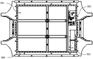
fig. 5 is a top view of a battery module set according to an embodiment of the invention.
Reference numerals
001. An electric core; 002. The vehicle-mounted charger and direct current converter integrated unit;
003. a high voltage distribution box; 004. A floor;
005. a seat mounting assembly; 006. A battery frame;
007. gluing; 008. A brake pipe;
009. an air suspension snorkel; 010. A threshold beam;
011. a threshold inner plate; 012. A front harness interface;
013. a rear harness interface; 014. A left front torque box;
015. a right front torque box; 016. A left rear torque box;
017. a right rear torque box; 018. A floor connection point;
019. a first connection point; 020. An upper body;
021. a second connection point; 022. A torsion box connection point;
023. a third connection point.
Detailed Description
In order to make the above and other features and advantages of the present invention more apparent, the present invention is further described below with reference to the accompanying drawings. It is understood that the specific embodiments described herein are for purposes of illustration only and are not intended to be limiting.
In the description of the present invention, it is to be understood that the terms "central," "longitudinal," "lateral," "length," "width," "thickness," "upper," "lower," "front," "rear," "left," "right," "vertical," "horizontal," "top," "bottom," "inner," "outer," "clockwise," "counterclockwise," "axial," "radial," "circumferential," and the like are used in the orientations and positional relationships indicated in the drawings for convenience in describing the invention and to simplify the description, and are not intended to indicate or imply that the referenced device or element must have a particular orientation, be constructed and operated in a particular orientation, and are not to be considered limiting of the invention.
Furthermore, the terms "first", "second" and "first" are used for descriptive purposes only and are not to be construed as indicating or implying relative importance or implicitly indicating the number of technical features indicated. Thus, a feature defined as "first" or "second" may explicitly or implicitly include at least one of the feature. In the description of the present invention, "a plurality" means at least two, e.g., two, three, etc., unless specifically limited otherwise.
In the present invention, unless otherwise expressly stated or limited, the terms "mounted," "connected," "secured," and the like are to be construed broadly and can, for example, be fixedly connected, detachably connected, or integrally formed; can be mechanically or electrically connected; they may be directly connected or indirectly connected through intervening media, or they may be connected internally or in any other suitable relationship, unless expressly stated otherwise. The specific meanings of the above terms in the present invention can be understood by those skilled in the art according to specific situations.
In the present invention, unless otherwise expressly stated or limited, the first feature "on" or "under" the second feature may be directly contacting the first and second features or indirectly contacting the first and second features through an intermediate. Also, a first feature "on," "above," and "over" a second feature may be directly on or obliquely above the second feature, or simply mean that the first feature is at a higher level than the second feature. A first feature being "under," "below," and "beneath" a second feature may be directly under or obliquely under the first feature, or may simply mean that the first feature is at a lesser elevation than the second feature.
As shown in fig. 1 to 5, the present invention provides an electric vehicle directly equipped with a battery cell 001, including:
the battery module group is used for assembling a lower vehicle body and comprises a battery frame 006, and a battery core 001 and a high-voltage accessory which are arranged in the battery frame 006;
the upper vehicle body 020 is arranged on the battery module group;
the torsion box is arranged on the battery module group;
wherein, battery frame 006 both sides and the junction of last automobile body 020 are the trapezium structure of multilayer, go up all be equipped with the tie point of being connected with last automobile body 020 mutually supporting on every layer of trapezium structure of automobile body 020.
The application makes the following design in order to practice thrift the Z of car to the space: 1. integrating the battery cell 001 and the high-voltage accessory in a lower automobile body; 2. a floor 004 structure of a conventional automobile is used as an upper cover of the battery frame 006; 3. the cooling structure of the battery module group is integrated in the floor 004, so that the situation that the space of a chassis is occupied by the battery pack structure is avoided, the Z-direction space of the whole automobile is optimized, the number of parts of the whole automobile is reduced, the development cost and the manufacturing cost of the whole automobile are reduced, the light weight design of the whole automobile is realized, and the driving range is improved.
It can be understood that the dc converter (dc converter: DCDC) mentioned in the present invention is worth to be a converter for converting dc power voltage into any dc voltage, and the vehicle-mounted charger (vehicle-mounted charger OBC) mainly has the following functions: the voltage of a power grid is connected to a vehicle-mounted charger through a ground alternating-current charging pile and an alternating-current charging port to charge an electric battery, and the DCDC and the OBC are integrated in one package to form DCDC and OBC; a high voltage Distribution box 003 (BDU), also called a Battery disconnection Unit (Battery disconnection Unit), is an important accessory in a high voltage circuit of a new energy vehicle; the front suspension is a suspension connected with a front axle and mainly comprises parts such as a steel plate spring, a shock absorber, a transverse stabilizer bar, a buffer block and the like, and the rear suspension has the same principle and is an air suspension in the application; the automobile X, Y, Z direction refers to: x-longitudinal direction, and positive direction along the central line direction of the whole vehicle; y-lateral direction, and the same plane with the X axis is vertical to the X axis to the left; z-vertical direction, vertically up to the XY plane.
In summary, the battery 001 and the high-voltage accessories are assembled in the battery frame 006 and integrated into the battery module group as a part of the lower vehicle body, the torque box is installed on the battery module group to prevent the battery module group from being damaged by the moment generated by the impact of the vehicle, the safety of the electric vehicle is improved, the upper vehicle body 020 is directly connected with the battery module group, the connection position of the battery frame 006 and the upper vehicle body 020 in the battery module group is set to be a multilayer trapezoidal structure, and the battery module group and the upper vehicle body 020 can be connected only through the connection point by arranging the connection point matched and connected with the upper vehicle body 020 on each layer of trapezoidal structure, so that the upper vehicle body 020 is directly connected with the battery module group, and the upper vehicle body 020 and the battery module group can be directly assembled and formed on a bus after the lower vehicle body is assembled by the battery module group; meanwhile, since the connection points are disposed on each of the ladder structures on both sides of the battery frame 006, when the length of the upper body 020 in the X direction does not change, the connection structure does not need to be redesigned, and the structural design of the lower body does not need to be changed, so that the development and design of the upper body 020 of the vehicle are facilitated.
Referring further to fig. 2, in a further aspect of the present invention, the electric vehicle further includes: a floor 004, which is covered on the battery frame 006; battery frame 006 is the mouth font by the concatenation of stake body section bar, and battery frame 006 encloses with floor 004 and establishes into the battery installation cavity, and high-voltage accessory sets up in the battery installation cavity with electric core 001, and high-voltage accessory is connected with electric core 001 electricity for charge for electric core 001.
In this scheme, through with floor 004 direct package on battery frame 006, floor 004 both regards as the floor 004 structure of conventional car, also regard as the top encapsulation board of battery installation cavity simultaneously, can further reduce the car under the car occupy of Z direction space, install high-voltage accessory and electric core 001 in battery frame 006 simultaneously, realize electric core 001, the high-voltage accessory integration is on the lower automobile body, battery frame 006 can provide the protecting effect for electric core 001 and high-voltage accessory with floor 004, high-voltage accessory is connected with electric core 001 electricity, also be connected with the interface electricity that charges simultaneously, it can be connected for electric core 001 charging source to fill electric pile or other through the interface that charges with the external world, and then realize charging for electric core 001 high voltage.
For the battery installation cavity, other structures can be arranged in the battery installation cavity to provide a supporting effect for the floor 004, specifically, a supporting frame is arranged in the battery installation cavity and comprises two supporting longitudinal beams and a cross beam vertically connected with the two supporting assemblies, the two supporting longitudinal beams are parallel to each other, the battery installation cavity is divided into a plurality of small cavities by the supporting frame, and the battery core 001 is installed in the small cavities by being divided into small battery cores 001.
In a further aspect of the present invention, the bracket body section is provided with a floor connection point 018, the floor 004 is connected to the battery frame 006 through the floor connection point 018, and the floor connection point 018 is in a bolt connection structure.
In this scheme, through set up floor connecting point 018 on battery frame 006's stake body section bar, floor 004 is connected to the rethread connecting point, therefore can obtain the effective support of battery frame 006's stake body section bar around floor 004, also can set up other support piece in the battery cavity simultaneously and provide the supporting effect for floor 004.
Referring further to fig. 2, in a further aspect of the invention, a seat mount assembly 005 is secured to the floor 004 by glue 007, the seat mount assembly 005 comprising: first crossbeam, second crossbeam, third crossbeam and mount pad, the both ends of first crossbeam, second crossbeam, third crossbeam all set up on battery frame 006, and wherein, the mount pad setting is on first crossbeam and second crossbeam, and first crossbeam, second crossbeam and third crossbeam are parallel to each other.
In this scheme, through setting up seat installation component 005 (detailed sign does not in the specific structure picture), the automobile of being convenient for is the direct mount seat when the equipment, through with first crossbeam, the second crossbeam, the both ends direct mount of third crossbeam is on battery frame 006, make battery frame 006 can be first crossbeam, the second crossbeam, the third crossbeam provides effective support, through set up the mount pad on first crossbeam and second crossbeam, the front seat in the direct mount automobile of being convenient for, back seat can the direct mount on the third crossbeam, for better for back seat provides the holding power, still can set up two longerons on the third crossbeam, install respectively on the stake body of third crossbeam and battery frame 006 at the both ends of longeron, thereby better for the back seat of automobile provides the holding power.
In a further aspect of the present invention, a wire harness interface (the wire harness interface includes a front wire harness interface 012 and a rear wire harness interface 013) is respectively disposed at the front end and the rear end of the battery module group, and a power supply interface (not shown) and a cooling interface (not shown) are disposed on the wire harness interface, where the power supply interface is electrically connected to the battery cell 001 and the high voltage accessory, and the cooling interface is communicated with the cooling structure of the battery module group.
In this scheme, through with power supply interface and cooling interface integration on the pencil interface, can avoid installing various types of interfaces additional on battery module group, power supply interface is direct to be connected with electric core 001 and high-voltage annex and the interface electricity that charges simultaneously, and then can realize charging for electric core 001, cooling interface and cooling interface intercommunication, can provide the cooling effect for battery module group, be convenient for promote the performance of electric core 001 in the battery module group, and on the same hand, other structures that are connected with battery module group still can be installed to the pencil interface, this paper is no longer redundantly repeated.
In a further aspect of the present invention, the cooling structure includes a cooling water channel (not identified in the figures) disposed in the floor 004 for cooling the electric core 001 and the high voltage accessories; the cooling interface comprises a water inlet (not marked in the figure) and a water outlet (not marked in the figure), which are respectively communicated with two ends of the cooling water channel, and the water inlet and the water outlet are used for entering and exiting the heat exchange medium.
In this scheme, through the integrated in floor 004 of cooling structure with battery module group, set up the cooling water course in floor 004 promptly, the Z of saving car that can be further is to the space, through design cooling water course in floor 004, the water inlet on the rethread wiring harness interface is linked together with the cooling system of delivery port and car, the heat that electric core 001 and high-voltage fittings gived off in the battery module group is absorbed to the heat transfer medium through cooling system cooling, and then the realization is to the heat retaining effect of battery module group, therefore can effectual promotion battery module group's performance.
Referring to fig. 4, in a further embodiment of the present invention, the connection point between the battery frame 006 and the upper body 020 is a two-layer ladder structure, the left and right sides of the battery frame 006 are respectively provided with a set of connection points for connecting the upper body 020, each set of connection points includes three first connection points 019 disposed on the upper layer and five second connection points 021 disposed on the lower layer, the first connection points 019 are used for connecting with the right sill beam 010 or the left sill beam 010 on the upper body 020, and the second connection points 021 are used for connecting with the sill inner panel 011 on the upper body 020.
In the scheme, two sides of the battery frame 006 are provided with an upper layer trapezoidal interface and a lower layer trapezoidal interface, a first connection point 019 and a second connection point 021 are respectively arranged on the upper layer and the lower layer, the left side first connection point 019 is connected with the left doorsill, the right side first 019 is connected with the right doorsill, and the second connection point 021 is connected with the doorsill inner plate 011 of the upper vehicle body 020; the two layers of connecting points are respectively connected with different parts of the upper vehicle body 020, so that the connecting stability can be improved, meanwhile, the efficiency of assembling the upper vehicle body and the lower vehicle body on a bus of the whole vehicle is improved,
in a further aspect of the present invention, the high voltage accessory comprises an on-board charger, a high voltage distribution box 003, and a dc converter, wherein at least two of the on-board charger, the high voltage distribution box 003, and the dc converter are integrated in one module; the on-board charger is identified with the dc converter integrated unit in fig. 1 as 002.
In this scheme, through with in on-vehicle charger, high voltage distribution box 003 and the direct current converter at least both integrations can be convenient for the maintenance of high-voltage accessory in a module, generally speaking, electric quantity distribution power and on-vehicle charger setting are in same module, and direct current converter sets up alone.
Referring to fig. 5, in a further embodiment of the present invention, the torsion boxes include a front left torsion box 014 and a front right torsion box 015 disposed at the front end of the battery module set, and a rear left torsion box 016 and a rear right torsion box 017 disposed at the rear end of the battery module set.
In a further aspect of the present invention, two torque box connection points 022 are disposed on each of two sides of the front and rear ends of the battery module set, and each of the two torque box connection points 022 is connected to one of the front left torque box 014, the front right torque box 015, the rear left torque box 016, and the rear right torque box 017, respectively.
In this scheme, both ends set up four torsion box tie points 022 respectively around battery frame 006 on battery module group, and two liang of settings are in the both sides at both ends around battery frame 006 respectively to torsion box tie point 022, and lug connection torsion box again also sets up the tie point on the upper surface of torsion box for be connected with last automobile body 020.
In a further aspect of the invention, three third connection points 023 are provided at the middle of the battery mounting cavity, the third connection points 023 penetrate through the floor 004, and the third connection points 023 are used for connecting the upper vehicle body 020.
In this scheme, through set up third tie point 023 in the battery installation cavity to run through floor 004, and then connect upper automobile body 020, can further improve battery module group and last automobile body 020's joint strength, third tie point 023 can adopt the pillar form simultaneously, can provide effectual support for floor 004's middle part.
In a further aspect of the present invention, the first connection point 019, the second connection point 021, the third connection point 023 and the torsion box connection point 022 all adopt a bolt connection structure.
In a further aspect of the present invention, passages communicating the front end and the rear end of the vehicle body are provided in the bracket body profiles on both sides of the battery frame 006, and the passages include a brake pipe 008 and an air suspension vent pipe 009, wherein the brake pipe 008 and the air suspension vent pipe 009 are located in the bracket body profile on the same side or in the bracket body profiles on both sides, respectively (the illustration is not provided in this aspect).
In the scheme, the brake pipeline 008 and the air suspension vent pipe 009 are arranged in the bracket body of the battery frame 006, so that the additional installation of pipelines on the vehicle body can be avoided, and further the management of automobile parts is simplified; need not to fix on automobile body or battery frame 006, reduced the fixed bolster quantity, optimized the overall arrangement of pipeline, made the pipeline of chassis arrange and level and smooth, reduce and go up pipeline when automobile body 020 attaches together and insert.
The scheme provided by the application enables the automobile structure to realize high-degree integration and modularization, and optimizes the overall design structure of the automobile; the battery core 001 and the high-voltage accessory are integrated into the electric automobile frame in a three-in-one manner, the chassis structure is optimized, more batteries can be arranged in a limited space, and the driving range of the whole automobile is expanded and improved; the battery frame 006 and the vehicle body floor 004 are designed in an integrated mode in structure and function, the indoor space is increased, the number of parts is reduced, and the development cost of the whole vehicle is reduced.
Further, it should be understood by those skilled in the art that, if an electric vehicle with a directly assembled battery cell provided by the embodiment of the present invention is used, all or part of the related sub-modules are combined and replaced by fusing, simple changing, mutual changing, and the like, for example, each component is placed at a moving position; or the products formed by the components are integrally arranged; or a detachable design; it is within the scope of the present disclosure that any combination of components may be combined into a device/apparatus/system having the specified functionality, and it is within the scope of the present disclosure to replace the corresponding components of the present disclosure with such a device/apparatus/system.
In the description herein, references to the description of the term "one embodiment," "some embodiments," "an example," "a specific example," or "some examples," etc., mean that a particular feature, structure, material, or characteristic described in connection with the embodiment or example is included in at least one embodiment or example of the invention. In this specification, the schematic representations of the terms used above are not necessarily intended to refer to the same embodiment or example. Furthermore, the particular features, structures, materials, or characteristics described may be combined in any suitable manner in any one or more embodiments or examples. Furthermore, various embodiments or examples and features of different embodiments or examples described in this specification can be combined and combined by one skilled in the art without contradiction.
Although embodiments of the present invention have been shown and described above, it will be understood that the above embodiments are exemplary and not to be construed as limiting the present invention, and that changes, modifications, substitutions and alterations can be made to the above embodiments by those of ordinary skill in the art within the scope of the present invention.
Claims (13)
1. An electric automobile of direct assembly electric core, its characterized in that includes:
the battery module group is used for assembling a lower vehicle body and comprises a battery frame, and a battery core and a high-voltage accessory which are arranged in the battery frame;
the upper vehicle body is mounted on the battery module group;
the torsion box is arranged on the battery module group;
the battery frame comprises an upper vehicle body and a lower vehicle body, wherein the upper vehicle body is provided with a plurality of layers of trapezoidal structures at the joints of the two sides of the battery frame and the upper vehicle body, and each layer of the trapezoidal structures of the upper vehicle body is provided with connecting points which are matched and connected with the upper vehicle body.
2. The electric vehicle with the directly assembled battery cell of claim 1, further comprising: the floor is covered on the battery frame; the battery frame is a square by the concatenation of stake body section bar, the battery frame with the floor encloses and establishes into the battery installation cavity, high-pressure annex with electric core set up in the battery installation cavity, high-pressure annex with electric core electricity is connected, is used for doing electric core charges.
3. The electric vehicle with the directly assembled battery cell as claimed in claim 2, wherein: the bracket body section is provided with a floor connecting point, the floor is connected with the battery frame through the floor connecting point, and the floor connecting point adopts a bolt connecting structure.
4. The electric vehicle with the directly assembled battery cell of claim 2, characterized in that: be fixed with seat installation component through the rubber coating on the floor, seat installation component includes: the battery frame comprises a first cross beam, a second cross beam, a third cross beam and a mounting seat, wherein the two ends of the first cross beam, the two ends of the second cross beam and the two ends of the third cross beam are arranged on the battery frame, the mounting seat is arranged on the first cross beam and the second cross beam, and the first cross beam, the second cross beam and the third cross beam are parallel to each other.
5. The electric vehicle accessory directly assembled with the battery cell of claim 2, characterized in that: the battery module group is characterized in that the front end and the rear end of the battery module group are respectively provided with a wire harness interface, the wire harness interfaces are provided with a power supply interface and a cooling interface, the power supply interface is electrically connected with the battery core and the high-voltage accessory, and the cooling interface is communicated with a cooling structure of the battery module group.
6. The electric vehicle with the directly assembled battery cell as claimed in claim 5, wherein: the cooling structure comprises a cooling water channel arranged in the floor and used for cooling the battery core and the high-voltage accessory; the cooling interface comprises a water inlet and a water outlet which are respectively communicated with two ends of the cooling water channel, and the water inlet and the water outlet are used for entering and exiting heat exchange media.
7. The electric vehicle with the directly assembled battery cell as claimed in any one of claims 2 to 6, wherein: the battery frame with the junction of going up the automobile body is upper and lower two-layer trapezium structure, the battery frame left and right sides respectively is equipped with a set of connection go up the tie point of automobile body, every group the tie point all includes the three first tie point that sets up on the upper strata and sets up five second tie points on the lower floor, first tie point be used for with go up right threshold roof beam or left threshold roof beam connection on the automobile body, the second tie point be used for with threshold inner panel on the last automobile body is connected.
8. The electric vehicle accessory directly assembled with the battery core as recited in claim 7, wherein: the high-voltage accessory comprises an on-board charger, a high-voltage distribution box and a direct-current converter, wherein at least two of the on-board charger, the high-voltage distribution box and the direct-current converter are integrated in one module.
9. The electric vehicle with the directly assembled battery cell as claimed in claim 7, wherein: the torsion box comprises a left front torsion box and a right front torsion box which are arranged at the front end of the battery module group, and a left rear torsion box and a right rear torsion box which are arranged at the rear end of the battery module group.
10. The electric vehicle with the directly assembled battery cell of claim 9, wherein: two sides of the front end and the rear end of the battery module group are respectively provided with two torsion box connection points, and every two torsion box connection points are respectively connected with one of the left front torsion box, the right front torsion box, the left rear torsion box and the right rear torsion box.
11. The electric vehicle with the directly assembled battery cell of claim 10, wherein: the middle part of the battery installation cavity is provided with three third connection points, the third connection points penetrate through the floor, and the third connection points are used for being connected with the upper vehicle body.
12. The electric vehicle with the directly assembled battery cell of claim 11, characterized in that: and the first connecting point, the second connecting point, the third connecting point and the torsion box connecting point are all in bolt connecting structures.
13. The electric vehicle with the directly assembled battery cell as claimed in claim 7, wherein: the support body section bars on two sides of the battery frame are internally provided with channels which are communicated with the front end and the rear end of the vehicle body, each channel comprises a brake pipeline and an air suspension ventilating pipe, and the brake pipelines and the air suspension ventilating pipes are positioned in the support body section bars on the same side or in the support body section bars on two sides respectively.
Priority Applications (1)
| Application Number | Priority Date | Filing Date | Title |
|---|---|---|---|
| CN202211299491.5A CN115570963A (en) | 2022-10-21 | 2022-10-21 | Electric automobile of direct assembly electricity core |
Applications Claiming Priority (1)
| Application Number | Priority Date | Filing Date | Title |
|---|---|---|---|
| CN202211299491.5A CN115570963A (en) | 2022-10-21 | 2022-10-21 | Electric automobile of direct assembly electricity core |
Publications (1)
| Publication Number | Publication Date |
|---|---|
| CN115570963A true CN115570963A (en) | 2023-01-06 |
Family
ID=84586741
Family Applications (1)
| Application Number | Title | Priority Date | Filing Date |
|---|---|---|---|
| CN202211299491.5A Pending CN115570963A (en) | 2022-10-21 | 2022-10-21 | Electric automobile of direct assembly electricity core |
Country Status (1)
| Country | Link |
|---|---|
| CN (1) | CN115570963A (en) |
-
2022
- 2022-10-21 CN CN202211299491.5A patent/CN115570963A/en active Pending
Similar Documents
| Publication | Publication Date | Title |
|---|---|---|
| CN113548117B (en) | Vehicle body floor assembly and vehicle | |
| KR102382679B1 (en) | Integrated Flatform Chassis Where Battery, Motor and Frame are Integrated Into One | |
| CN213108967U (en) | Hydrogen supply frame system arranged in subareas | |
| CN113787920B (en) | Chassis arrangement structure of hydrogen fuel tractor and hydrogen fuel tractor | |
| CN205044508U (en) | Arrangement structure of distributing type four -wheel in -wheel motor driving electric automobile's power battery group | |
| CN219544890U (en) | Frame of electric light truck | |
| CN115570963A (en) | Electric automobile of direct assembly electricity core | |
| JPH09118140A (en) | Electric vehicle using large capacity electric double layer capacitor as power source | |
| CN114750829B (en) | Chassis framework, chassis platform and electric vehicle | |
| CN103158519A (en) | Battery pack installation structure of electric vehicle | |
| CN112599914B (en) | Power battery panel beating lower box assembly structure | |
| CN114590115A (en) | Vehicle with a steering wheel | |
| CN111469648A (en) | Low-floor pure electric bus | |
| CN217361754U (en) | High integrated battery package buffer structure of car and car | |
| CN218703475U (en) | Integrated chassis and vehicle | |
| CN215321964U (en) | Middle-mounted power battery system arrangement structure based on light commercial vehicle | |
| CN214984770U (en) | Power assembly system and electric automobile | |
| CN218430868U (en) | Chassis arrangement structure of fuel cell tractor | |
| CN209912931U (en) | Novel lower box body of battery pack | |
| CN114889696B (en) | Electric automobile | |
| CN115635843A (en) | Back hydrogen storage sleeve frame structure and hydrogen fuel truck | |
| CN216301228U (en) | Chassis framework of new energy low-floor passenger car | |
| CN217198355U (en) | Body structure of new energy automobile CTC | |
| CN219856777U (en) | Vehicle with a vehicle body having a vehicle body support | |
| CN220809556U (en) | Power distribution vehicle body structure and vehicle |
Legal Events
| Date | Code | Title | Description |
|---|---|---|---|
| PB01 | Publication | ||
| PB01 | Publication | ||
| SE01 | Entry into force of request for substantive examination | ||
| SE01 | Entry into force of request for substantive examination |