CN115569566A - Mud solidification agitating unit - Google Patents
Mud solidification agitating unit Download PDFInfo
- Publication number
- CN115569566A CN115569566A CN202211477021.3A CN202211477021A CN115569566A CN 115569566 A CN115569566 A CN 115569566A CN 202211477021 A CN202211477021 A CN 202211477021A CN 115569566 A CN115569566 A CN 115569566A
- Authority
- CN
- China
- Prior art keywords
- fixedly connected
- shell
- solidification
- mixing
- gear
- Prior art date
- Legal status (The legal status is an assumption and is not a legal conclusion. Google has not performed a legal analysis and makes no representation as to the accuracy of the status listed.)
- Granted
Links
Images


Classifications
-
- B—PERFORMING OPERATIONS; TRANSPORTING
- B01—PHYSICAL OR CHEMICAL PROCESSES OR APPARATUS IN GENERAL
- B01F—MIXING, e.g. DISSOLVING, EMULSIFYING OR DISPERSING
- B01F27/00—Mixers with rotary stirring devices in fixed receptacles; Kneaders
- B01F27/80—Mixers with rotary stirring devices in fixed receptacles; Kneaders with stirrers rotating about a substantially vertical axis
- B01F27/92—Mixers with rotary stirring devices in fixed receptacles; Kneaders with stirrers rotating about a substantially vertical axis with helices or screws
- B01F27/921—Mixers with rotary stirring devices in fixed receptacles; Kneaders with stirrers rotating about a substantially vertical axis with helices or screws with helices centrally mounted in the receptacle
-
- B—PERFORMING OPERATIONS; TRANSPORTING
- B01—PHYSICAL OR CHEMICAL PROCESSES OR APPARATUS IN GENERAL
- B01F—MIXING, e.g. DISSOLVING, EMULSIFYING OR DISPERSING
- B01F27/00—Mixers with rotary stirring devices in fixed receptacles; Kneaders
- B01F27/80—Mixers with rotary stirring devices in fixed receptacles; Kneaders with stirrers rotating about a substantially vertical axis
- B01F27/808—Mixers with rotary stirring devices in fixed receptacles; Kneaders with stirrers rotating about a substantially vertical axis with stirrers driven from the bottom of the receptacle
-
- B—PERFORMING OPERATIONS; TRANSPORTING
- B01—PHYSICAL OR CHEMICAL PROCESSES OR APPARATUS IN GENERAL
- B01F—MIXING, e.g. DISSOLVING, EMULSIFYING OR DISPERSING
- B01F33/00—Other mixers; Mixing plants; Combinations of mixers
- B01F33/80—Mixing plants; Combinations of mixers
- B01F33/83—Mixing plants specially adapted for mixing in combination with disintegrating operations
-
- B—PERFORMING OPERATIONS; TRANSPORTING
- B01—PHYSICAL OR CHEMICAL PROCESSES OR APPARATUS IN GENERAL
- B01F—MIXING, e.g. DISSOLVING, EMULSIFYING OR DISPERSING
- B01F33/00—Other mixers; Mixing plants; Combinations of mixers
- B01F33/80—Mixing plants; Combinations of mixers
- B01F33/836—Mixing plants; Combinations of mixers combining mixing with other treatments
- B01F33/8361—Mixing plants; Combinations of mixers combining mixing with other treatments with disintegrating
- B01F33/83613—Mixing plants; Combinations of mixers combining mixing with other treatments with disintegrating by grinding or milling
-
- B—PERFORMING OPERATIONS; TRANSPORTING
- B01—PHYSICAL OR CHEMICAL PROCESSES OR APPARATUS IN GENERAL
- B01F—MIXING, e.g. DISSOLVING, EMULSIFYING OR DISPERSING
- B01F35/00—Accessories for mixers; Auxiliary operations or auxiliary devices; Parts or details of general application
- B01F35/10—Maintenance of mixers
- B01F35/12—Maintenance of mixers using mechanical means
- B01F35/123—Maintenance of mixers using mechanical means using scrapers for cleaning mixers
-
- B—PERFORMING OPERATIONS; TRANSPORTING
- B01—PHYSICAL OR CHEMICAL PROCESSES OR APPARATUS IN GENERAL
- B01F—MIXING, e.g. DISSOLVING, EMULSIFYING OR DISPERSING
- B01F35/00—Accessories for mixers; Auxiliary operations or auxiliary devices; Parts or details of general application
- B01F35/71—Feed mechanisms
-
- B—PERFORMING OPERATIONS; TRANSPORTING
- B01—PHYSICAL OR CHEMICAL PROCESSES OR APPARATUS IN GENERAL
- B01F—MIXING, e.g. DISSOLVING, EMULSIFYING OR DISPERSING
- B01F35/00—Accessories for mixers; Auxiliary operations or auxiliary devices; Parts or details of general application
- B01F35/90—Heating or cooling systems
- B01F35/92—Heating or cooling systems for heating the outside of the receptacle, e.g. heated jackets or burners
-
- C—CHEMISTRY; METALLURGY
- C02—TREATMENT OF WATER, WASTE WATER, SEWAGE, OR SLUDGE
- C02F—TREATMENT OF WATER, WASTE WATER, SEWAGE, OR SLUDGE
- C02F11/00—Treatment of sludge; Devices therefor
- C02F11/008—Sludge treatment by fixation or solidification
Abstract
The invention relates to the technical field of sludge solidification, and discloses a sludge solidification mixing device which comprises a shell, wherein the lower end of the shell is fixedly connected with a supporting leg, the upper end of the shell is provided with a feeding hole, the outer side of the shell is provided with a discharging hole, the inner side of the shell is fixedly connected with a mixing barrel, the outer side of the mixing barrel is wound with a heating pipe, the lower end of the shell is provided with a stirring assembly, the stirring assembly comprises a motor, an output shaft of the motor is fixedly connected with a connecting column, the upper end of the connecting column is fixedly connected with a rotary drum, the outer side of the rotary drum is fixedly connected with a connecting drum, and the outer side of the connecting drum is fixedly connected with a spiral sheet. This mud sediment solidification mixing arrangement can improve the mixing efficiency of curing agent, reduces and mixes used time, and can smash the caking with the mud sediment, guarantees the solidification efficiency of mud sediment, more can clear up the mud sediment that the blending vessel inner wall is infected with, makes things convenient for the cleanness of blending vessel.
Description
Technical Field
The invention relates to the technical field of sludge solidification, in particular to a sludge solidification stirring device.
Background
At present, five main methods for curing sludge at home and abroad comprise: the method comprises the steps of mud throwing treatment, dredger fill land building, physical dehydration, incineration and chemical solidification, wherein the solidification treatment method is the most suitable treatment method for treating dredged mud residues in large scale at present. The chemical curing treatment is to add curing materials into the sludge, and the curing agents and water are caused to generate a series of physical and chemical reactions by stirring and mixing to change the mechanical property of the sludge, so that the properties of high water content and low strength of the sludge can be improved, the treated sludge has the properties of high strength and low permeability, the sludge curing agents can be divided into high-molecular curing agents, chemical curing agents and biological enzyme curing agents, a compound curing agent is adopted according to the national conditions, the mixture ratio which is not used can be set according to different reinforcement purposes, the advantages of the chemical curing agent are low cost, convenient material drawing and good stability, and the defect is that the early strength is not high.
The prior sludge and curing agent have the following disadvantages when mixed: 1. mixing to ensure that the sludge and the mixing agent are fully mixed by long-time stirring; 2. the caking in the sludge can not be mixed with the curing agent, so that the curing effect of the sludge is influenced; 3. the sludge can be remained on the inner wall of the stirring barrel and is difficult to clean; for this purpose, we propose a sludge solidification mixing device.
Disclosure of Invention
Solves the technical problem
Aiming at the defects of the prior art, the invention provides a mud residue curing and stirring device which can improve the mixing efficiency of a curing agent, reduce the time for mixing, crush lumps in mud residues to ensure the curing efficiency of the mud residues, clean the mud residues stained on the inner wall of a mixing barrel and facilitate the cleaning of the mixing barrel.
Technical scheme
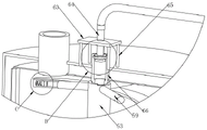
In order to realize the above, the invention provides the following technical scheme that the mixing efficiency of the curing agent can be improved, the mixing time is shortened, the caking in the sludge can be crushed to ensure the curing efficiency of the sludge, the sludge infected by the inner wall of the mixing barrel can be cleaned, and the cleaning of the mixing barrel is convenient: the utility model provides a mud sediment solidification agitating unit, includes the shell, the lower extreme fixedly connected with supporting leg of shell, the upper end of shell is provided with the feed inlet, the outside of shell is provided with the discharge gate, the inboard fixedly connected with blending drum of shell, the outside winding of blending drum has the heating pipe, the lower extreme of shell is provided with the stirring subassembly, the stirring subassembly includes the motor, the output shaft fixedly connected with spliced pole of motor, the upper end fixedly connected with rotary drum of spliced pole, the outside fixedly connected with connecting cylinder of rotary drum, the outside fixedly connected with flight of connecting cylinder, the upper end of shell is provided with the pay-off subassembly that adds solution to the blending drum inboard, the inboard of blending drum is provided with rolls the subassembly.
Preferably, the feeding assembly comprises a water pump, four groups of supporting columns are fixedly connected to the upper end of the shell, four groups of supporting columns are fixedly connected to the upper end of the fixing plate, a spray head is fixedly connected to the inner side of the fixing plate, a water pipe is fixedly connected to the upper end of the spray head, and one end of the water pipe is connected with the water pump.
Preferably, the upper end of the rotating cylinder is provided with a connecting pipe, the inner side of the connecting pipe is fixedly connected with a sealing bearing, the lower end of the spray head extends to the inner side of the connecting pipe through the sealing bearing, and the lower end of the spray head is fixedly connected with a second retaining ring.
Preferably, an opening is formed in the outer side of the connecting cylinder, a first check ring is fixedly connected to the inner side of the connecting cylinder, a spring is fixedly connected to one end of the inside of the connecting cylinder, a blocking ring is fixedly connected to one end of the spring, and the connecting cylinder is communicated with the rotary drum.
Preferably, the grinding assembly includes the protective housing, protective housing and spliced pole fixed connection, the inner wall bottom fixedly connected with backing plate of blending tank, the first gear of upper end fixedly connected with of backing plate, the spliced pole is connected with backing plate, first gear revolve, the outside fixedly connected with connecting plate of the top spliced pole of protective housing, the lower extreme fixedly connected with of connecting plate changes the board, the inboard rotation of changeing the board is connected with the pivot, the one end fixedly connected with second gear of pivot, the second gear meshes with first gear mutually, the other end fixedly connected with grinding wheel of pivot.
Preferably, the front end fixedly connected with intercepting net of connecting plate, the front end fixedly connected with extension board of intercepting net, the lower extreme and the laminating of running roller mutually of extension board, intercepting net is network structure.
Preferably, the one end fixedly connected with scraper blade of connecting plate, the one end and the scraper blade of running roller rotate to be connected, the scraper blade is laminated with the blending barrel mutually, the one end and the circular-arc of intercepting net.
Preferably, the rotating opening is formed in the outer side of the base plate, a clamping ring is fixedly connected to the inner wall of the protective shell, and the clamping ring is rotatably connected to the inner side of the rotating opening.
Advantageous effects
Compared with the prior art, the invention provides a sludge solidification mixing device which has the following beneficial effects:
1. this a mud sediment solidification mixing device, enable the spliced pole through the motor and drive the rotary drum and rotate, it rotates to drive the flight through the connecting cylinder, stir the mud sediment, also can stir the mud sediment through the connecting cylinder, increase the stirring efficiency of mud sediment, then start the water pump extraction and mix the good coagulant mixed liquid, the inboard of shower nozzle is injected into to the through-water pipe, then pour into the inboard of rotary drum into, curing agent solution can get into the inboard of connecting cylinder, then promote the block collar and make the spring shrink, then curing agent solution can pass through the opening blowout, make the inside of mixing drum spray everywhere, increase the mixing efficiency of mud sediment, the spring can promote the opening and plug up the opening again after the water pump stops, prevent that the mud sediment from pouring into the inboard of connecting cylinder, the rotary drum rotates and can drive the connecting pipe and rotate, make sealed bearing rotate in the outside of shower nozzle, prevent that the shower nozzle from rotating, can fix the shower nozzle through the fixed plate.
2. This a mud sediment solidification mixing arrangement, the spliced pole rotates simultaneously and can drives the protective housing and make the rand rotate in the inboard of changeing the mouth, can prevent through the protective housing that mud sediment from polluting the second gear, the backing plate, the spliced pole can drive the connecting plate and rotate simultaneously, make the commentaries on classics board drive the grinding wheel and roll the caking, the second gear can rotate on first gear simultaneously and make the pivot, guarantee that the grinding wheel rotates on changeing the board, can filter the rejection caking to mud sediment through the interception net, and the interception net can stir the mud sediment of mixing barrel lower extreme, further improve the mixing efficiency of mud sediment, make the caking can follow the below that the extension board landing arrives the grinding wheel, guarantee the efficiency of rolling of grinding wheel, the mud sediment that is infected with on the extension board can clear up the grinding wheel simultaneously.
3. This mud sediment solidification agitating unit, mud sediment discharge back can drive the scraper blade through the connecting plate and slide at the inner wall of blending tank, clears up the lateral wall, can heat the blending tank through the heating pipe, makes the dry convenient scraper blade of mud sediment of blending tank inner wall to the clearance of blending tank, and the heating pipe can heat the mud sediment when the mud sediment mixes simultaneously, increases the inboard moisture of mud sediment and discharges, increases the solidification efficiency of mud sediment.
Drawings
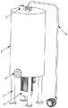
FIG. 1 is a schematic view of the overall structure of the present invention;
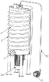
FIG. 2 is a first cross-sectional view of the present invention;
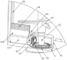
FIG. 3 is a second cross-sectional view of the present invention;
FIG. 4 is a third cross-sectional view of the present invention;
FIG. 5 is a first partial schematic view of the present invention;
FIG. 6 is an enlarged view of part A of the present invention;
FIG. 7 is a second partial schematic view of the present invention;
FIG. 8 is an enlarged view of part B of the present invention;
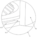
fig. 9 is an enlarged view of part C of the present invention.
In the figure: 1. a housing; 2. supporting legs; 3. a feed inlet; 4. a discharge port; 5. a stirring assembly; 51. a motor; 52. connecting columns; 53. a rotating drum; 54. a spiral sheet; 55. a connecting cylinder; 56. a first retainer ring; 57. a spring; 58. plugging a ring; 59. an opening; 6. a feeding assembly; 61. a water pump; 62. a water pipe; 63. a fixing plate; 64. a spray head; 65. a support pillar; 66. a connecting pipe; 67. sealing the bearing; 68. a second retainer ring; 7. heating a tube; 8. rolling the component; 81. a protective shell; 82. a base plate; 83. a first gear; 84. a second gear; 85. a rotating shaft; 86. a connecting plate; 87. rotating the plate; 88. a squeegee; 89. an intercepting net; 810. an extension plate; 811. grinding the wheel; 812. turning the opening; 813. a collar; 9. and (4) a mixing barrel.
Detailed Description
The technical solutions in the embodiments of the present invention will be clearly and completely described below with reference to the drawings in the embodiments of the present invention, and it is obvious that the described embodiments are only a part of the embodiments of the present invention, and not all of the embodiments. All other embodiments, which can be obtained by a person skilled in the art without making any creative effort based on the embodiments in the present invention, belong to the protection scope of the present invention.
Referring to fig. 1-9, a mud residue solidification mixing device, including shell 1, the lower extreme fixedly connected with supporting leg 2 of shell 1, the upper end of shell 1 is provided with feed inlet 3, the outside of shell 1 is provided with discharge gate 4, the inboard fixedly connected with blending barrel 9 of shell 1, the outside winding of blending barrel 9 has heating pipe 7, the lower extreme of shell 1 is provided with stirring subassembly 5, stirring subassembly 5 includes motor 51, the output shaft fixedly connected with spliced pole 52 of motor 51, the upper end fixedly connected with rotary drum 53 of spliced pole 52, the outside fixedly connected with connecting cylinder 55 of rotary drum 53, the outside fixedly connected with flight 54 of connecting cylinder 55, the upper end of shell 1 is provided with the pay-off subassembly 6 of adding solution to the inboard of blending barrel 9, the inboard of blending barrel 9 is provided with rolls subassembly 8.
In this embodiment, the feeding assembly 6 includes a water pump 61, four groups of support columns 65 are fixedly connected to the upper end of the housing 1, a fixing plate 63 is fixedly connected to the upper ends of the four groups of support columns 65, a nozzle 64 is fixedly connected to the inner side of the fixing plate 63, a water pipe 62 is fixedly connected to the upper end of the nozzle 64, and one end of the water pipe 62 is connected to the water pump 61.
Specifically, the water pump 61 is started to pump the mixed coagulant solution, the mixed coagulant solution is injected into the inner side of the spray head 64 through the water pipe 62 and then injected into the inner side of the rotary drum 53, the spray head 64 can be fixed through the support column 65 and the fixing plate 63, and the spray head 64 is prevented from rotating along with the connecting pipe 66.
In this embodiment, a connection pipe 66 is installed at the upper end of the drum 53, a sealing bearing 67 is fixedly connected to the inner side of the connection pipe 66, the lower end of the nozzle 64 extends to the inner side of the connection pipe 66 through the sealing bearing 67, and a second retainer 68 is fixedly connected to the lower end of the nozzle 64.
Specifically, the rotation of the drum 53 drives the connection tube 66 to rotate, so that the seal bearing 67 rotates outside the spray head 64 to prevent the spray head 64 from rotating.
In this embodiment, an opening 59 is formed on an outer side of the connecting cylinder 55, a first retainer ring 56 is fixedly connected to an inner side of the connecting cylinder 55, a spring 57 is fixedly connected to one end of the inside of the connecting cylinder 55, a stopper ring 58 is fixedly connected to one end of the spring 57, and the connecting cylinder 55 is communicated with the rotary drum 53.
Specifically, curing agent solution can get into the inboard of connecting cylinder 55, then promote stifled circle 58 and make spring 57 shrink, then the solidification liquid can be through opening 59 blowout, make the mixed liquid can spray mixing drum 9's inside everywhere, increase the mixing efficiency of mud sediment, spring 57 can promote opening 59 to block up opening 59 again after water pump 61 stops, prevent that the mud sediment from pouring into the inboard of connecting cylinder 55, can be with stifled circle 58 bumping post through first retaining ring 56, prevent that stifled circle 58 from crossing opening 59.
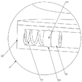
In this embodiment, rolling component 8 includes protective housing 81, protective housing 81 and spliced pole 52 fixed connection, the inner wall bottom fixedly connected with backing plate 82 of blending bin 9, the first gear 83 of upper end fixedly connected with of backing plate 82, spliced pole 52 and backing plate 82, first gear 83 rotates and is connected, the outside fixedly connected with connecting plate 86 of the top spliced pole 52 of protective housing 81, the lower extreme fixedly connected with of connecting plate 86 changes board 87, the inboard rotation of changeing board 87 is connected with pivot 85, the one end fixedly connected with second gear 84 of pivot 85, second gear 84 meshes with first gear 83 mutually, the other end fixedly connected with grinding wheel 811 of pivot 85.
The front end fixedly connected with intercepting net 89 of connecting plate 86, the front end fixedly connected with extension board 810 of intercepting net 89, the lower extreme and the laminating of running roller 811 mutually of extension board 810, intercepting net 89 is network structure.
Specifically, can prevent through protective housing 81 that the mud sediment from polluting second gear 84, backing plate 82, spliced pole 52 can drive connecting plate 86 and rotate simultaneously, make and change board 87 and drive running roller 811 and roll the knot, second gear 84 can rotate messenger's pivot 85 on first gear 83 simultaneously, guarantee that running roller 811 rotates on changeing board 87, can filter the rejection caking to the mud sediment through interception net 89, make the caking can follow extension board 810 landing to the below of running roller 811, guarantee the efficiency of rolling of running roller 811, the mud sediment that is infected with on extension board 810 can clear up running roller 811 simultaneously.
In this embodiment, one end of the connecting plate 86 is fixedly connected with a scraper 88, one end of the grinding wheel 811 is rotatably connected with the scraper 88, the scraper 88 is attached to the mixing barrel 9, and one end of the intercepting net 89 is arc-shaped.
Specifically, can clear up the inner wall of tempering tank 9 through scraper blade 88, guarantee the cleanness of tempering tank 9 inner wall, increase tempering tank 9's clean efficiency.
In this embodiment, a rotating opening 812 is formed on the outer side of the backing plate 82, a clamping ring 813 is fixedly connected to the inner wall of the protective shell 81, and the clamping ring 813 is rotatably connected to the inner side of the rotating opening 812.
Specifically, the connecting column 52 rotates to drive the protective shell 81 to enable the clamping ring 813 to rotate on the inner side of the rotating port 812, and the protective shell 81 can be conveniently rotated through the clamping ring 813 and the rotating port 812.
In operation, the mud is added to the inner side of the mixing barrel 9 through the feed inlet 3, the motor 51 is started, the connecting column 52 is used for driving the rotary drum 53 to rotate, the spiral piece 54 is driven to rotate through the connecting cylinder 55, the mud is stirred, the water pump 61 is started to extract the mixed curing agent solution, the curing agent solution is injected into the inner side of the spray head 64 through the water pipe 62 and then injected into the inner side of the rotary drum 53, the curing agent solution can enter the inner side of the connecting cylinder 55, the blocking ring 58 is pushed to contract the spring 57, the curing agent solution can be sprayed out through the opening 59, the spring 57 can push the blocking ring 58 to block the opening 59 again after the water pump 61 is stopped, the rotary drum 53 can drive the connecting pipe 66 to rotate, the sealing bearing 67 rotates on the outer side of the spray head 64 to prevent the spray head 64 from rotating, the connecting column 52 can drive the protective shell 81 to enable the clamping ring 813 to rotate on the inner side of the rotary opening 812, the connecting column 52 can drive the connecting plate 86 to rotate, the rotary plate 87 can be driven to roll the sundries, the rolling wheel 811, meanwhile, the second gear 84 can drive the rolling wheel 811 to drive the rolling wheel 85 to drive the rolling wheel 811 through the rolling scraper 813 through the inner wall 88, the rotary plate 87 to heat the inner wall of the mixing barrel 9, and the scraper blade 88 can heat the mixing barrel 7.
It is noted that, herein, relational terms such as first and second, and the like may be used solely to distinguish one entity or action from another entity or action without necessarily requiring or implying any actual such relationship or order between such entities or actions. Also, the terms "comprises," "comprising," or any other variation thereof, are intended to cover a non-exclusive inclusion, such that a process, method, article, or apparatus that comprises a list of elements does not include only those elements but may include other elements not expressly listed or inherent to such process, method, article, or apparatus.
Although embodiments of the present invention have been shown and described, it will be appreciated by those skilled in the art that changes, modifications, substitutions and alterations can be made in these embodiments without departing from the principles and spirit of the invention, the scope of which is defined in the appended claims and their equivalents.
Claims (8)
1. A mud solidification mixing device, includes shell (1), its characterized in that: the utility model discloses a mixing drum, including shell (1), lower extreme fixedly connected with supporting leg (2) of shell (1), the upper end of shell (1) is provided with feed inlet (3), the outside of shell (1) is provided with discharge gate (4), inboard fixedly connected with blending bunker (9) of shell (1), the outside winding of blending bunker (9) has heating pipe (7), the lower extreme of shell (1) is provided with stirring subassembly (5), stirring subassembly (5) include motor (51), the output shaft fixedly connected with spliced pole (52) of motor (51), the upper end fixedly connected with rotary drum (53) of spliced pole (52), the outside fixedly connected with connecting cylinder (55) of rotary drum (53), the outside fixedly connected with flight (54) of connecting cylinder (55), the upper end of shell (1) is provided with pay-off subassembly (6) to adding solution to blending bunker (9) inboard, the inboard of blending bunker (9) is provided with rolls subassembly (8).
2. A sludge solidification and mixing device as claimed in claim 1, wherein the feeding assembly (6) comprises a water pump (61), four groups of supporting columns (65) are fixedly connected to the upper end of the casing (1), a fixing plate (63) is fixedly connected to the upper ends of the four groups of supporting columns (65), a spray head (64) is fixedly connected to the inner side of the fixing plate (63), a water pipe (62) is fixedly connected to the upper end of the spray head (64), and one end of the water pipe (62) is connected with the water pump (61).
3. A sludge solidification and mixing device as claimed in claim 2, wherein the upper end of the rotary drum (53) is provided with a connecting pipe (66), the inner side of the connecting pipe (66) is fixedly connected with a sealing bearing (67), the lower end of the spray head (64) extends to the inner side of the connecting pipe (66) through the sealing bearing (67), and the lower end of the spray head (64) is fixedly connected with a second retainer (68).
4. A mud solidification and mixing device as claimed in claim 1, wherein an opening (59) is opened on the outer side of the connecting cylinder (55), a first retainer ring (56) is fixedly connected on the inner side of the connecting cylinder (55), a spring (57) is fixedly connected at one end of the inner part of the connecting cylinder (55), a blocking ring (58) is fixedly connected at one end of the spring (57), and the connecting cylinder (55) is communicated with the rotary cylinder (53).
5. A sludge solidification and mixing apparatus as claimed in claim 1, wherein: roll subassembly (8) including protective housing (81), protective housing (81) and spliced pole (52) fixed connection, the inner wall bottom fixedly connected with backing plate (82) of blending bin (9), the first gear (83) of upper end fixedly connected with of backing plate (82), spliced pole (52) rotate with backing plate (82), first gear (83) and are connected, outside fixedly connected with connecting plate (86) of top spliced pole (52) of protective housing (81), the lower extreme fixedly connected with of connecting plate (86) changes board (87), the inboard rotation of changeing board (87) is connected with pivot (85), the one end fixedly connected with second gear (84) of pivot (85), second gear (84) mesh mutually with first gear (83), the other end fixedly connected with grinding wheel (811) of pivot (85).
6. A sludge solidification and mixing apparatus as claimed in claim 5, wherein: the front end fixedly connected with interception net (89) of connecting plate (86), the front end fixedly connected with of interception net (89) extends board (810), the lower extreme and the laminating of running roller (811) of extending board (810) mutually, interception net (89) are network structure.
7. A sludge solidification mixing apparatus as claimed in claim 6, wherein: one end fixedly connected with scraper blade (88) of connecting plate (86), the one end and scraper blade (88) of grinding wheel (811) are rotated and are connected, scraper blade (88) and blending barrel (9) are laminated mutually, the one end and the circular-arc of intercepting net (89).
8. A sludge solidification mixing apparatus as claimed in claim 6, wherein: the rotating opening (812) is formed in the outer side of the base plate (82), a clamping ring (813) is fixedly connected to the inner wall of the protective shell (81), and the clamping ring (813) is rotatably connected to the inner side of the rotating opening (812).
Priority Applications (1)
| Application Number | Priority Date | Filing Date | Title |
|---|---|---|---|
| CN202211477021.3A CN115569566B (en) | 2022-11-23 | 2022-11-23 | Mud residue solidification mixing device |
Applications Claiming Priority (1)
| Application Number | Priority Date | Filing Date | Title |
|---|---|---|---|
| CN202211477021.3A CN115569566B (en) | 2022-11-23 | 2022-11-23 | Mud residue solidification mixing device |
Publications (2)
| Publication Number | Publication Date |
|---|---|
| CN115569566A true CN115569566A (en) | 2023-01-06 |
| CN115569566B CN115569566B (en) | 2023-06-23 |
Family
ID=84590148
Family Applications (1)
| Application Number | Title | Priority Date | Filing Date |
|---|---|---|---|
| CN202211477021.3A Active CN115569566B (en) | 2022-11-23 | 2022-11-23 | Mud residue solidification mixing device |
Country Status (1)
| Country | Link |
|---|---|
| CN (1) | CN115569566B (en) |
Cited By (1)
| Publication number | Priority date | Publication date | Assignee | Title |
|---|---|---|---|---|
| CN115970534A (en) * | 2023-03-17 | 2023-04-18 | 河北正翔防火材料有限公司 | Stirring device for preparing fireproof coating and stirring method thereof |
Citations (4)
| Publication number | Priority date | Publication date | Assignee | Title |
|---|---|---|---|---|
| CN213703994U (en) * | 2020-10-29 | 2021-07-16 | 爱德森堡新材料有限公司 | Concrete processing equipment convenient to maintain |
| CN113926341A (en) * | 2021-11-22 | 2022-01-14 | 湖南新澧化工有限公司 | Coal slime solidification upgrading agent processing device |
| CN217163972U (en) * | 2021-09-08 | 2022-08-12 | 苏州纪喆环保科技有限公司 | Flocculating agent preparation facilities |
| CN217313037U (en) * | 2022-04-15 | 2022-08-30 | 陕西金基石新型建材有限公司 | Cleaning assembly of automatic mud stirring device |
-
2022
- 2022-11-23 CN CN202211477021.3A patent/CN115569566B/en active Active
Patent Citations (4)
| Publication number | Priority date | Publication date | Assignee | Title |
|---|---|---|---|---|
| CN213703994U (en) * | 2020-10-29 | 2021-07-16 | 爱德森堡新材料有限公司 | Concrete processing equipment convenient to maintain |
| CN217163972U (en) * | 2021-09-08 | 2022-08-12 | 苏州纪喆环保科技有限公司 | Flocculating agent preparation facilities |
| CN113926341A (en) * | 2021-11-22 | 2022-01-14 | 湖南新澧化工有限公司 | Coal slime solidification upgrading agent processing device |
| CN217313037U (en) * | 2022-04-15 | 2022-08-30 | 陕西金基石新型建材有限公司 | Cleaning assembly of automatic mud stirring device |
Cited By (2)
| Publication number | Priority date | Publication date | Assignee | Title |
|---|---|---|---|---|
| CN115970534A (en) * | 2023-03-17 | 2023-04-18 | 河北正翔防火材料有限公司 | Stirring device for preparing fireproof coating and stirring method thereof |
| CN115970534B (en) * | 2023-03-17 | 2023-06-27 | 河北正翔防火材料有限公司 | Stirring device for fireproof paint preparation and stirring method thereof |
Also Published As
| Publication number | Publication date |
|---|---|
| CN115569566B (en) | 2023-06-23 |
Similar Documents
| Publication | Publication Date | Title |
|---|---|---|
| CN109569365A (en) | A kind of food liquid detection pretreatment unit with agitating function | |
| CN108465438A (en) | One kind being convenient for clean wet granulator | |
| CN115569566A (en) | Mud solidification agitating unit | |
| CN112253472A (en) | Automatic control drainage system of centrifugal pump | |
| CN110694326A (en) | Concrete waste recycling system | |
| CN109013680A (en) | It is a kind of to crush and be stirred the soil restoring device being integrated with particle | |
| CN105421563B (en) | The technique of concret waste water comprehensive reutilization system | |
| CN216963652U (en) | Improvement type chemical industry liquid material sedimentation tank | |
| CN216367470U (en) | Water based paint mixes cauldron | |
| CN213865664U (en) | Prevent food and beverage sewage treatment plant of jam | |
| CN214263208U (en) | Movable soil remediation device | |
| CN211917248U (en) | Forced mixer convenient to it is clean | |
| CN207031208U (en) | A kind of molysite retracting device of iron containing sludge | |
| CN218170892U (en) | Concrete mixing device permeates water convenient to it is reinforced | |
| CN216881015U (en) | Semi-automatic urban soil pollution prosthetic devices | |
| CN220409195U (en) | Cement pouring equipment | |
| CN108722658A (en) | A kind of water-saving dolly and its application method | |
| CN220745553U (en) | Sewage treatment aeration tank | |
| CN214982091U (en) | Concrete mixing plant | |
| CN209669029U (en) | A kind of php slurry harmless treatment device | |
| CN211078838U (en) | Adjustable nodal pattern sludge treatment system | |
| CN214438384U (en) | Flocculating agent solution agitating unit | |
| CN220661308U (en) | Mortar stirring device for building construction | |
| CN219114393U (en) | Equipment for producing polymer mortar | |
| CN219376851U (en) | Tuff mechanism sand compounding device |
Legal Events
| Date | Code | Title | Description |
|---|---|---|---|
| PB01 | Publication | ||
| PB01 | Publication | ||
| SE01 | Entry into force of request for substantive examination | ||
| SE01 | Entry into force of request for substantive examination | ||
| GR01 | Patent grant | ||
| GR01 | Patent grant |