CN115566315A - New energy automobile submergence formula liquid cooling battery pack - Google Patents
New energy automobile submergence formula liquid cooling battery pack Download PDFInfo
- Publication number
- CN115566315A CN115566315A CN202211238436.5A CN202211238436A CN115566315A CN 115566315 A CN115566315 A CN 115566315A CN 202211238436 A CN202211238436 A CN 202211238436A CN 115566315 A CN115566315 A CN 115566315A
- Authority
- CN
- China
- Prior art keywords
- battery pack
- liquid
- cooling
- box
- fixedly arranged
- Prior art date
- Legal status (The legal status is an assumption and is not a legal conclusion. Google has not performed a legal analysis and makes no representation as to the accuracy of the status listed.)
- Withdrawn
Links
Images


Classifications
-
- H—ELECTRICITY
- H01—ELECTRIC ELEMENTS
- H01M—PROCESSES OR MEANS, e.g. BATTERIES, FOR THE DIRECT CONVERSION OF CHEMICAL ENERGY INTO ELECTRICAL ENERGY
- H01M10/00—Secondary cells; Manufacture thereof
- H01M10/60—Heating or cooling; Temperature control
- H01M10/61—Types of temperature control
- H01M10/613—Cooling or keeping cold
-
- H—ELECTRICITY
- H01—ELECTRIC ELEMENTS
- H01M—PROCESSES OR MEANS, e.g. BATTERIES, FOR THE DIRECT CONVERSION OF CHEMICAL ENERGY INTO ELECTRICAL ENERGY
- H01M10/00—Secondary cells; Manufacture thereof
- H01M10/60—Heating or cooling; Temperature control
- H01M10/62—Heating or cooling; Temperature control specially adapted for specific applications
- H01M10/625—Vehicles
-
- H—ELECTRICITY
- H01—ELECTRIC ELEMENTS
- H01M—PROCESSES OR MEANS, e.g. BATTERIES, FOR THE DIRECT CONVERSION OF CHEMICAL ENERGY INTO ELECTRICAL ENERGY
- H01M10/00—Secondary cells; Manufacture thereof
- H01M10/60—Heating or cooling; Temperature control
- H01M10/65—Means for temperature control structurally associated with the cells
- H01M10/655—Solid structures for heat exchange or heat conduction
- H01M10/6554—Rods or plates
-
- H—ELECTRICITY
- H01—ELECTRIC ELEMENTS
- H01M—PROCESSES OR MEANS, e.g. BATTERIES, FOR THE DIRECT CONVERSION OF CHEMICAL ENERGY INTO ELECTRICAL ENERGY
- H01M10/00—Secondary cells; Manufacture thereof
- H01M10/60—Heating or cooling; Temperature control
- H01M10/65—Means for temperature control structurally associated with the cells
- H01M10/655—Solid structures for heat exchange or heat conduction
- H01M10/6556—Solid parts with flow channel passages or pipes for heat exchange
-
- H—ELECTRICITY
- H01—ELECTRIC ELEMENTS
- H01M—PROCESSES OR MEANS, e.g. BATTERIES, FOR THE DIRECT CONVERSION OF CHEMICAL ENERGY INTO ELECTRICAL ENERGY
- H01M10/00—Secondary cells; Manufacture thereof
- H01M10/60—Heating or cooling; Temperature control
- H01M10/65—Means for temperature control structurally associated with the cells
- H01M10/656—Means for temperature control structurally associated with the cells characterised by the type of heat-exchange fluid
- H01M10/6561—Gases
- H01M10/6563—Gases with forced flow, e.g. by blowers
-
- H—ELECTRICITY
- H01—ELECTRIC ELEMENTS
- H01M—PROCESSES OR MEANS, e.g. BATTERIES, FOR THE DIRECT CONVERSION OF CHEMICAL ENERGY INTO ELECTRICAL ENERGY
- H01M10/00—Secondary cells; Manufacture thereof
- H01M10/60—Heating or cooling; Temperature control
- H01M10/65—Means for temperature control structurally associated with the cells
- H01M10/656—Means for temperature control structurally associated with the cells characterised by the type of heat-exchange fluid
- H01M10/6567—Liquids
- H01M10/6568—Liquids characterised by flow circuits, e.g. loops, located externally to the cells or cell casings
-
- H—ELECTRICITY
- H01—ELECTRIC ELEMENTS
- H01M—PROCESSES OR MEANS, e.g. BATTERIES, FOR THE DIRECT CONVERSION OF CHEMICAL ENERGY INTO ELECTRICAL ENERGY
- H01M50/00—Constructional details or processes of manufacture of the non-active parts of electrochemical cells other than fuel cells, e.g. hybrid cells
- H01M50/20—Mountings; Secondary casings or frames; Racks, modules or packs; Suspension devices; Shock absorbers; Transport or carrying devices; Holders
- H01M50/233—Mountings; Secondary casings or frames; Racks, modules or packs; Suspension devices; Shock absorbers; Transport or carrying devices; Holders characterised by physical properties of casings or racks, e.g. dimensions
- H01M50/242—Mountings; Secondary casings or frames; Racks, modules or packs; Suspension devices; Shock absorbers; Transport or carrying devices; Holders characterised by physical properties of casings or racks, e.g. dimensions adapted for protecting batteries against vibrations, collision impact or swelling
-
- H—ELECTRICITY
- H01—ELECTRIC ELEMENTS
- H01M—PROCESSES OR MEANS, e.g. BATTERIES, FOR THE DIRECT CONVERSION OF CHEMICAL ENERGY INTO ELECTRICAL ENERGY
- H01M50/00—Constructional details or processes of manufacture of the non-active parts of electrochemical cells other than fuel cells, e.g. hybrid cells
- H01M50/20—Mountings; Secondary casings or frames; Racks, modules or packs; Suspension devices; Shock absorbers; Transport or carrying devices; Holders
- H01M50/244—Secondary casings; Racks; Suspension devices; Carrying devices; Holders characterised by their mounting method
-
- H—ELECTRICITY
- H01—ELECTRIC ELEMENTS
- H01M—PROCESSES OR MEANS, e.g. BATTERIES, FOR THE DIRECT CONVERSION OF CHEMICAL ENERGY INTO ELECTRICAL ENERGY
- H01M50/00—Constructional details or processes of manufacture of the non-active parts of electrochemical cells other than fuel cells, e.g. hybrid cells
- H01M50/20—Mountings; Secondary casings or frames; Racks, modules or packs; Suspension devices; Shock absorbers; Transport or carrying devices; Holders
- H01M50/249—Mountings; Secondary casings or frames; Racks, modules or packs; Suspension devices; Shock absorbers; Transport or carrying devices; Holders specially adapted for aircraft or vehicles, e.g. cars or trains
-
- Y—GENERAL TAGGING OF NEW TECHNOLOGICAL DEVELOPMENTS; GENERAL TAGGING OF CROSS-SECTIONAL TECHNOLOGIES SPANNING OVER SEVERAL SECTIONS OF THE IPC; TECHNICAL SUBJECTS COVERED BY FORMER USPC CROSS-REFERENCE ART COLLECTIONS [XRACs] AND DIGESTS
- Y02—TECHNOLOGIES OR APPLICATIONS FOR MITIGATION OR ADAPTATION AGAINST CLIMATE CHANGE
- Y02E—REDUCTION OF GREENHOUSE GAS [GHG] EMISSIONS, RELATED TO ENERGY GENERATION, TRANSMISSION OR DISTRIBUTION
- Y02E60/00—Enabling technologies; Technologies with a potential or indirect contribution to GHG emissions mitigation
- Y02E60/10—Energy storage using batteries
Abstract
The invention discloses an immersed liquid-cooled battery pack of a new energy automobile, which comprises: installing a base; the shock pad is fixedly arranged in the middle of the top end of the mounting base; the battery pack box is arranged at the top end of the shock pad; a cooling circulation assembly disposed at a front side of the battery pack case; the cooling liquid recycling and filling mechanism is arranged on the rear side of the battery pack box; and the buffering and damping mechanism is arranged between the battery pack box and the mounting base. According to the immersed liquid-cooled battery pack of the new energy automobile, the cooling liquid in the battery pack box can be circulated through the cooling circulation assembly, and the circulated cooling liquid is cooled to reduce the temperature of the cooling liquid and ensure the heat dissipation effect.
Description
Technical Field
The invention relates to the technical field of energy storage batteries, in particular to an immersed liquid-cooled battery assembly of a new energy automobile.
Background
The new energy automobile adopts unconventional automobile fuel as a power source (or adopts conventional automobile fuel and a novel vehicle-mounted power device), integrates advanced technologies in the aspects of power control and driving of the automobile, forms an automobile with advanced technical principle, new technology and new structure, and comprises a pure electric automobile, an extended range electric automobile, a hybrid electric automobile, a fuel cell electric automobile, a hydrogen engine automobile and the like;
the new energy automobile mostly adopts an electric storage lithium battery, and the battery energy storage technology is an energy storage technology which has a good application prospect and is developed rapidly at present and occupies a mainstream position in an electrochemical energy storage market;
but at present electric power storage lithium cell generally adopts the air-cooled technique to carry out ambient temperature's control, and the radiating efficiency is low to adjust ambient temperature through the air, the rate of change of temperature is slower, thereby seriously influences electric power storage lithium cell's life, and the group battery can cause under receiving strong vibrations to connect not hard up in the use, influences the use.
Disclosure of Invention
The invention aims to provide an immersed liquid-cooled battery pack of a new energy automobile, which aims to solve the problems in the background technology.
In order to achieve the purpose, the invention provides the following technical scheme: the utility model provides a new energy automobile submergence formula liquid cooling battery pack, includes:
installing a base;
the shock pad is fixedly arranged in the middle of the top end of the mounting base;
the battery pack box is arranged at the top end of the shock pad;
a cooling circulation assembly disposed at a front side of the battery pack case;
the cooling liquid recycling and filling mechanism is arranged on the rear side of the battery pack box;
and the buffering and damping mechanism is arranged between the battery pack box and the mounting base.
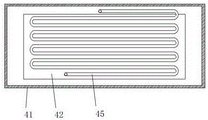
Preferably, in order to cool down the cooling liquid in the battery box in a circulating manner, the cooling circulating assembly includes: the cooling shell is fixedly arranged on the front side of the battery pack box; the heat conducting plate is in adaptive insertion connection with the front side of the cooling shell; the first water pump is fixedly arranged at the bottom end of the inner cavity of the cooling shell; the water inlet of the first water pump is in threaded connection with a water inlet pipe, and one end of the water inlet pipe is in threaded connection with the bottom end of the front side of the battery pack box; a water outlet of the first water pump is connected with a first water outlet pipe in a threaded manner, and one end of the first water outlet pipe extends into the top end of the inner cavity of the cooling shell; and the heat radiation fan is fixedly arranged on the front side of the cooling shell and is positioned on the front side of the heat conducting plate.
Preferably, the water inlet pipe is fixedly arranged on the front side of the inner cavity of the cooling shell in a snake shape.
Preferably, under the suction action of the first water pump, the cooling liquid in the battery pack box is sucked out by the water inlet pipe and is discharged back into the battery pack box through the first water outlet pipe, and when the cooling liquid passes through the water inlet pipe, the cooling fan is started to reduce the temperature of the heat conducting plate, so that the water inlet pipe arranged at the rear side of the heat conducting plate can be cooled, and the cooling liquid absorbing heat in the battery pack box can be cooled and reflows into the battery pack box from above to complete the circulation of the cooling liquid, so as to reduce the temperature of the cooling liquid.
Preferably, the cooling liquid recovery and filling mechanism includes: the battery pack top cover is fixedly arranged at the top end of the inner cavity of the battery pack box, and a plurality of liquid outlet holes are formed in the top end of the battery pack top cover; the liquid storage box is fixedly arranged at the bottom end of the rear side of the battery pack box; the condenser pipe is fixedly arranged at the top end of the rear side of the battery pack box, the condenser pipe is communicated with the inner cavity of the battery pack box, and one end of the condenser pipe extends into the inner cavity of the liquid storage box; the second water pump is fixedly arranged at the top end of the liquid storage tank, and a water inlet of the second water pump extends into the inner cavity of the liquid storage tank; a water outlet of the second water pump is in threaded connection with a second water outlet pipe, and one end of the second water outlet pipe extends into the top end of the rear side of the inner cavity of the battery pack box; the liquid level meter is fixedly arranged at the bottom end of the battery pack top cover and is electrically connected with the second water pump.
Preferably, the condensation pipe is inclined from top to bottom towards the rear side.
Preferably, one end of the condensation duct is positioned above the top cover of the battery pack.
Preferably, when the cooling liquid in the battery pack box is heated, evaporated gas can flow into the liquid storage box through the liquefaction of the condensation pipe, so that the loss of the cooling liquid is reduced, and when the cooling liquid in the battery pack box is low and the liquid level meter is used, the second water pump can be controlled to be started, so that the cooling liquid stored in the liquid storage box is supplemented into the battery pack box through the second water outlet pipe, and the timely supplement of the cooling liquid is completed.
Preferably, in order to reduce the vibration to which the battery pack case is subjected, the damping mechanism includes: the left side and the right side of the top end of the mounting base are fixedly provided with side plates; the front end and the rear end of the inner side of the side plate are respectively provided with a first limiting column in a rotating way through a pin shaft; the second limiting column is in adaptive insertion connection with the inner cavity of the first limiting column and is rotatably connected with the outer side of the battery pack box through a pin shaft; and the damping spring is fixedly arranged between the side plate and the battery pack box, and is sleeved with the outer walls of the first limiting column and the second limiting column.
Preferably, the first limiting column and the second limiting column are arranged in an upward inclined mode from outside to inside.
The invention provides an immersed liquid-cooled battery pack of a new energy automobile, which has the beneficial effects that:
1. the cooling circulation assembly is arranged, so that the cooling liquid in the battery pack box can be circulated, and the circulated cooling liquid is cooled, so that the temperature of the cooling liquid is reduced, and the heat dissipation effect is ensured;
2. the cooling liquid recycling and filling mechanism is arranged, so that the loss of the cooling liquid can be reduced, and the cooling liquid in the liquid storage tank can be supplemented into the battery pack box through monitoring of the liquid level meter, so that the cooling liquid can be supplemented in time;
3. the buffering and damping mechanism is arranged to prevent the battery pack box from being vibrated in the vertical and horizontal directions, so that the internal damage of the battery pack box can be avoided, and the service life of the battery pack box is prolonged.
Drawings
FIG. 1 is a schematic structural view of the present invention;
FIG. 2 is an enlarged view taken at A in FIG. 1 according to the present invention;
FIG. 3 is a left side elevation view of the present invention;
FIG. 4 is a front cross-sectional view of the present invention;
FIG. 5 is a rear side cross-sectional view of the cooling jacket of the present invention.
In the figure: 1. the installation base, 2, the shock pad, 3, the battery box, 4, the cooling cycle subassembly, 41, the cooling shell, 42, the heat-conducting plate, 43, first water pump, 44, the inlet tube, 45, first outlet pipe, 46, radiator fan, 5, coolant liquid recovery filling mechanism, 51, the group battery top cap, 52, go out the liquid hole, 53, the liquid reserve tank, 54, the condenser pipe, 55, the second water pump, 56, the second outlet pipe, 57, the level gauge, 6, buffering damper, 61, the curb plate, 62, first spacing post, 63, the spacing post of second, 64, damping spring.
Detailed Description
The technical solutions in the embodiments of the present invention will be clearly and completely described below with reference to the drawings in the embodiments of the present invention, and it is obvious that the described embodiments are only a part of the embodiments of the present invention, and not all of the embodiments. All other embodiments, which can be obtained by a person skilled in the art without making any creative effort based on the embodiments in the present invention, belong to the protection scope of the present invention.
Referring to fig. 1-5, the present invention provides a technical solution: the utility model provides a new energy automobile submergence formula liquid cooling battery pack, includes: the method comprises the following steps that (1) a base, a shock pad 2, a battery pack box 3, a cooling circulation assembly 4, a cooling liquid recycling and filling mechanism 5 and a buffering and shock absorbing mechanism 6 are installed;
the shock pad 2 is fixed to be set up in the top middle part of installation base 1, and battery pack box 3 is installed on the top of shock pad 2, and cooling cycle subassembly 4 sets up in battery pack box 3's front side, and the coolant liquid is retrieved and is filled 5 settings in battery pack box 3's rear side, and buffering damper 6 sets up between battery pack box 3 and installation base 1.
Preferably, the cooling circulation module 4 further includes: a cooling shell 41, a heat conducting plate 42, a first water pump 43, a water inlet pipe 44, a first water outlet pipe 45 and a heat radiating fan 46;
in order to make the heat dissipation in the cooling case 41 faster by providing the heat conducting plate 42, the cooling case 41 is fixedly provided at the front side of the battery pack box 3, and the heat conducting plate 42 is fittingly inserted into the front side of the cooling case 41;
in order to circulate the cooling liquid in the battery pack box 3, the first water pump 43 is fixedly arranged at the bottom end of the inner cavity of the cooling shell 41, a water inlet of the first water pump 43 is in threaded connection with a water inlet pipe 44, one end of the water inlet pipe 44 is in threaded connection with the bottom end of the front side of the battery pack box 3, a water outlet of the first water pump 43 is in threaded connection with a first water outlet pipe 45, and one end of the first water outlet pipe 45 extends into the top end of the inner cavity of the cooling shell 41;
in order to improve the heat radiation effect of the heat conductive plate 42, a heat radiation fan 46 is fixedly provided at the front side of the cooling case 41 and at the front side of the heat conductive plate 42.
Preferably, the water inlet pipe 44 is fixedly disposed at the front side of the inner cavity of the cooling shell 41 in a serpentine shape, so that the cooling liquid can be completely radiated when passing through the water inlet pipe 44.
Preferably, the cooling liquid recovery and filling mechanism 5 further includes: the battery pack comprises a battery pack top cover 51, a liquid outlet hole 52, a liquid storage tank 53, a condenser pipe 54, a second water pump 55, a second water outlet pipe 56 and a liquid level meter 57;
in order to collect the evaporated coolant, the battery pack top cover 51 is fixedly arranged at the top end of the inner cavity of the battery pack box 3, a plurality of liquid outlet holes 52 are formed in the top end of the battery pack top cover 51, the liquid storage box 53 is fixedly arranged at the bottom end of the rear side of the battery pack box 3, the condenser pipe 54 is fixedly arranged at the top end of the rear side of the battery pack box 3, the condenser pipe 54 is communicated with the inner cavity of the battery pack box 3, and one end of the condenser pipe 54 extends into the inner cavity of the liquid storage box 53;
in order to timely supplement the cooling liquid in the battery pack box 3, the second water pump 55 is fixedly arranged at the top end of the liquid storage box 53, the water inlet of the second water pump 55 extends into the inner cavity of the liquid storage box 53, the water outlet of the second water pump 55 is in threaded connection with a second water outlet pipe 56, one end of the second water outlet pipe 56 extends into the top end of the rear side of the inner cavity of the battery pack box 3, the liquid level meter 57 is fixedly arranged at the bottom end of the battery pack top cover 51, and the liquid level meter 57 is electrically connected with the second water pump 55.
Further, preferably, the condensation duct 54 is inclined from the top to the bottom toward the rear side so that the vaporized coolant condenses into water drops to fall into the reservoir tank 53.
Preferably, one end of the condensation duct 54 is positioned above the stack top cover 51 to allow the vaporized coolant to condense into the condensation duct 54.
Preferably, the shock absorbing mechanism 6 further includes: the side plate 61, the first limit column 62, the second limit column 63 and the damping spring 64;
in order to absorb shock of the battery pack box 3, side plates 61 are fixedly arranged on the left side and the right side of the top end of the mounting base 1, and first limiting columns 62 are rotatably arranged at the front end and the rear end of the inner side of each side plate 61 through pin shafts;
in order to enable the battery pack box 3 to be damped in the horizontal direction, the second limiting column 63 is connected with the inner cavity of the first limiting column 62 in an adaptive mode, the second limiting column 63 is rotatably connected with the outer side of the battery pack box 3 through a pin shaft, the damping spring 64 is fixedly arranged between the side plate 61 and the battery pack box 3, and the damping spring 64 is sleeved with the outer walls of the first limiting column 62 and the second limiting column 63.
It should be noted that the first position-limiting column 62 and the second position-limiting column 63 are inclined upward from outside to inside to ensure that the battery box 3 can be damped by the vibration in the up-down, left-right directions.
The detailed connection means is a technique known in the art, and the following mainly describes the working principle and process, and the specific operation is as follows.
The method comprises the following steps: putting the battery pack into the battery pack box 3, adding cooling liquid into the battery pack box 3 until the cooling liquid passes through the liquid level meter 57 and the battery pack top cover 51, switching on an external power supply of the heat dissipation fan 46, the first water pump 43, the second water pump 55 and the liquid level meter 57, controlling the first water pump 43 and the heat dissipation fan 46 to start, so that the cooling liquid in the battery pack box 3 is sucked out by the water inlet pipe 44 under the suction action of the first water pump 43 and is discharged back into the battery pack box 3 through the first water outlet pipe 45, and when the cooling liquid passes through the water inlet pipe 44, the heat dissipation fan 46 starts to reduce the temperature of the heat conduction plate 42, so that the water inlet pipe 44 arranged at the rear side of the heat conduction plate 42 can be cooled, and further the cooling liquid absorbing the heat in the battery pack box 3 can be cooled and flows back into the battery pack box 3 from the upper part to complete the circulation of the cooling liquid, so as to reduce the temperature of the cooling liquid and ensure the heat dissipation effect;
step two: when the cooling liquid in the battery pack box 3 is heated, evaporated gas can be liquefied by the condenser pipe 54 and flows into the liquid storage box 53, so that the loss of the cooling liquid is reduced, and when the cooling liquid in the battery pack box 3 is low and reaches the liquid level meter 57, the second water pump 55 can be controlled to be started, so that the cooling liquid stored in the liquid storage box 53 is supplemented into the battery pack box 3 through the second water outlet pipe 56, and the timely supplement of the cooling liquid is completed;
step three: after battery box 3 fixed mounting, when battery box 3 received vibrations, under the shock attenuation of first spacing post 62, the spacing post 63 of second and damping spring 64 to avoid battery box 3 to receive the vibrations of upper and lower left right direction, thereby can avoid battery box 3 inside impaired increase of service life.
Although embodiments of the present invention have been shown and described, it will be appreciated by those skilled in the art that changes, modifications, substitutions and alterations can be made in these embodiments without departing from the principles and spirit of the invention, the scope of which is defined in the appended claims and their equivalents.
Claims (8)
1. The utility model provides a new energy automobile submergence formula liquid cooling battery pack which characterized in that includes:
a mounting base (1);
the shock pad (2) is fixedly arranged in the middle of the top end of the mounting base (1);
the battery pack box (3) is installed at the top end of the shock pad (2);
a cooling circulation unit (4) provided on the front side of the battery pack case (3);
a cooling liquid recovery and filling mechanism (5) provided on the rear side of the battery pack case (3);
and the buffering and damping mechanism (6) is arranged between the battery pack box (3) and the mounting base (1).
2. The immersed liquid-cooled battery pack for the new energy automobile as claimed in claim 1, wherein: the cooling circulation assembly (4) includes:
a cooling case (41) fixedly provided on the front side of the battery pack case (3);
the heat conduction plate (42) is in adaptive insertion connection with the front side of the cooling shell (41);
the first water pump (43) is fixedly arranged at the bottom end of the inner cavity of the cooling shell (41);
the water inlet pipe (44) is connected to the water inlet of the first water pump (43) in a threaded mode, and one end of the water inlet pipe (44) is connected with the bottom end of the front side of the battery pack box (3) in a threaded mode;
a water outlet of the first water pump (43) is in threaded connection with the first water outlet pipe (45), and one end of the first water outlet pipe (45) extends into the top end of the inner cavity of the cooling shell (41);
and the heat radiation fan (46) is fixedly arranged on the front side of the cooling shell (41) and is positioned on the front side of the heat conduction plate (42).
3. The immersed liquid-cooled battery pack for the new energy automobile as claimed in claim 2, wherein: the water inlet pipe (44) is fixedly arranged on the front side of the inner cavity of the cooling shell (41) in a snake shape.
4. The immersed liquid-cooled battery pack for the new energy automobile as claimed in claim 1, wherein: the cooling liquid recovery and filling mechanism (5) comprises:
the battery pack top cover (51) is fixedly arranged at the top end of the inner cavity of the battery pack box (3), and a plurality of liquid outlet holes (52) are formed in the top end of the battery pack top cover (51);
the liquid storage tank (53) is fixedly arranged at the bottom end of the rear side of the battery pack box (3);
the condensation pipe (54) is fixedly arranged at the top end of the rear side of the battery pack box (3), the condensation pipe (54) is communicated with the inner cavity of the battery pack box (3), and one end of the condensation pipe (54) extends into the inner cavity of the liquid storage box (53);
the second water pump (55) is fixedly arranged at the top end of the liquid storage tank (53), and a water inlet of the second water pump (55) extends into an inner cavity of the liquid storage tank (53);
a water outlet of the second water pump (55) is in threaded connection with the second water outlet pipe (56), and one end of the second water outlet pipe (56) extends into the top end of the rear side of the inner cavity of the battery pack box (3);
the liquid level meter (57) is fixedly arranged at the bottom end of the battery pack top cover (51), and the liquid level meter (57) is electrically connected with the second water pump (55).
5. The immersed liquid-cooled battery pack for the new energy automobile as claimed in claim 4, wherein: the condensation pipe (54) is arranged obliquely from top to bottom towards the rear side.
6. The immersed liquid-cooled battery pack for the new energy automobile as claimed in claim 4, wherein: one end of the condensation pipe (54) is positioned above the battery pack top cover (51).
7. The immersed liquid-cooled battery pack for the new energy automobile as claimed in claim 1, wherein: the buffer damping mechanism (6) comprises:
the left side and the right side of the top end of the mounting base (1) are fixedly provided with side plates (61);
the front end and the rear end of the inner side of the side plate (61) are respectively provided with a first limiting column (62) in a rotating mode through a pin shaft;
the second limiting column (63) is in adaptive insertion connection with the inner cavity of the first limiting column (62), and the second limiting column (63) is rotatably connected with the outer side of the battery pack box (3) through a pin shaft;
and the damping spring (64) is fixedly arranged between the side plate (61) and the battery pack box (3), and the damping spring (64) is sleeved with the outer walls of the first limiting column (62) and the second limiting column (63).
8. The immersed liquid-cooled battery pack for the new energy automobile as claimed in claim 7, wherein: the first limiting column (62) and the second limiting column (63) are arranged in an upward inclined mode from outside to inside.
Priority Applications (1)
| Application Number | Priority Date | Filing Date | Title |
|---|---|---|---|
| CN202211238436.5A CN115566315A (en) | 2022-10-11 | 2022-10-11 | New energy automobile submergence formula liquid cooling battery pack |
Applications Claiming Priority (1)
| Application Number | Priority Date | Filing Date | Title |
|---|---|---|---|
| CN202211238436.5A CN115566315A (en) | 2022-10-11 | 2022-10-11 | New energy automobile submergence formula liquid cooling battery pack |
Publications (1)
| Publication Number | Publication Date |
|---|---|
| CN115566315A true CN115566315A (en) | 2023-01-03 |
Family
ID=84745990
Family Applications (1)
| Application Number | Title | Priority Date | Filing Date |
|---|---|---|---|
| CN202211238436.5A Withdrawn CN115566315A (en) | 2022-10-11 | 2022-10-11 | New energy automobile submergence formula liquid cooling battery pack |
Country Status (1)
| Country | Link |
|---|---|
| CN (1) | CN115566315A (en) |
Cited By (1)
| Publication number | Priority date | Publication date | Assignee | Title |
|---|---|---|---|---|
| CN116315343A (en) * | 2023-04-28 | 2023-06-23 | 湖北实美科技有限公司 | New energy vehicle aluminum alloy section bar battery box |
-
2022
- 2022-10-11 CN CN202211238436.5A patent/CN115566315A/en not_active Withdrawn
Cited By (2)
| Publication number | Priority date | Publication date | Assignee | Title |
|---|---|---|---|---|
| CN116315343A (en) * | 2023-04-28 | 2023-06-23 | 湖北实美科技有限公司 | New energy vehicle aluminum alloy section bar battery box |
| CN116315343B (en) * | 2023-04-28 | 2023-08-25 | 湖北实美科技有限公司 | New energy vehicle aluminum alloy section bar battery box |
Similar Documents
| Publication | Publication Date | Title |
|---|---|---|
| CN111129655A (en) | Self-discharge less and cycle number more integrated new energy automobile battery | |
| CN113241485B (en) | Increase battery package of phase transition heat transfer | |
| CN115566315A (en) | New energy automobile submergence formula liquid cooling battery pack | |
| CN106711545B (en) | A kind of high power battery group lug floating immersion type temperature-controlling system and method | |
| CN113809436A (en) | High-density energy storage battery module capable of rapidly dissipating heat | |
| CN112133981A (en) | New energy automobile lithium battery pack's heat dissipation protection auxiliary device | |
| CN112151913B (en) | Power battery and cooling device and cooling method thereof | |
| CN214706046U (en) | Phase change and air cooling combined battery heat dissipation system | |
| CN212659629U (en) | Heat dissipation battery case | |
| CN112582703B (en) | Novel battery cooling structure based on coupling of heat pipe and liquid cooling plate | |
| CN212230549U (en) | Graphene lithium battery structure with heat dissipation function | |
| CN212277300U (en) | Self-discharge less and cycle number more integrated new energy automobile battery | |
| CN112086705A (en) | Power battery heat dissipation method based on ionic liquid phase change material and liquid cooling | |
| CN209571523U (en) | A kind of battery modules radiator structure | |
| CN114284594A (en) | Battery and battery pack | |
| CN217507482U (en) | Power battery module with cooling mechanism | |
| CN219393495U (en) | New energy battery safety device | |
| CN220856698U (en) | Power battery temperature management device | |
| CN219203279U (en) | Battery pack with good heat dissipation performance | |
| CN219716997U (en) | New energy automobile power battery package structure | |
| CN220156329U (en) | New energy automobile driving motor | |
| CN212461906U (en) | Novel lithium battery bearing box for ship | |
| CN218975568U (en) | Battery compartment with good heat dissipation effect | |
| CN218769779U (en) | Three-sided water-cooled battery based on phase change heat transfer | |
| CN220324547U (en) | Energy storage battery module with self-cooling function |
Legal Events
| Date | Code | Title | Description |
|---|---|---|---|
| PB01 | Publication | ||
| PB01 | Publication | ||
| SE01 | Entry into force of request for substantive examination | ||
| SE01 | Entry into force of request for substantive examination | ||
| WW01 | Invention patent application withdrawn after publication | ||
| WW01 | Invention patent application withdrawn after publication |
Application publication date: 20230103 |