CN115532907A - Horizontal numerical control rounding machine - Google Patents
Horizontal numerical control rounding machine Download PDFInfo
- Publication number
- CN115532907A CN115532907A CN202211216227.0A CN202211216227A CN115532907A CN 115532907 A CN115532907 A CN 115532907A CN 202211216227 A CN202211216227 A CN 202211216227A CN 115532907 A CN115532907 A CN 115532907A
- Authority
- CN
- China
- Prior art keywords
- working roll
- working
- roll
- roller
- loading
- Prior art date
- Legal status (The legal status is an assumption and is not a legal conclusion. Google has not performed a legal analysis and makes no representation as to the accuracy of the status listed.)
- Pending
Links
- 238000013000 roll bending Methods 0.000 claims description 80
- 230000008859 change Effects 0.000 claims description 5
- 238000009434 installation Methods 0.000 claims description 3
- 239000000463 material Substances 0.000 abstract description 19
- 238000003825 pressing Methods 0.000 abstract description 5
- 238000000034 method Methods 0.000 description 8
- 238000005452 bending Methods 0.000 description 6
- 230000007246 mechanism Effects 0.000 description 5
- 230000008569 process Effects 0.000 description 5
- 230000017525 heat dissipation Effects 0.000 description 4
- 238000003754 machining Methods 0.000 description 4
- 230000009471 action Effects 0.000 description 3
- 238000005096 rolling process Methods 0.000 description 3
- 238000010586 diagram Methods 0.000 description 2
- 238000004519 manufacturing process Methods 0.000 description 2
- 230000002860 competitive effect Effects 0.000 description 1
- 230000007547 defect Effects 0.000 description 1
- 238000009826 distribution Methods 0.000 description 1
- 238000005516 engineering process Methods 0.000 description 1
- 238000011084 recovery Methods 0.000 description 1
- 238000004088 simulation Methods 0.000 description 1
Images


Classifications
-
- B—PERFORMING OPERATIONS; TRANSPORTING
- B21—MECHANICAL METAL-WORKING WITHOUT ESSENTIALLY REMOVING MATERIAL; PUNCHING METAL
- B21D—WORKING OR PROCESSING OF SHEET METAL OR METAL TUBES, RODS OR PROFILES WITHOUT ESSENTIALLY REMOVING MATERIAL; PUNCHING METAL
- B21D7/00—Bending rods, profiles, or tubes
- B21D7/08—Bending rods, profiles, or tubes by passing between rollers or through a curved die
-
- B—PERFORMING OPERATIONS; TRANSPORTING
- B21—MECHANICAL METAL-WORKING WITHOUT ESSENTIALLY REMOVING MATERIAL; PUNCHING METAL
- B21D—WORKING OR PROCESSING OF SHEET METAL OR METAL TUBES, RODS OR PROFILES WITHOUT ESSENTIALLY REMOVING MATERIAL; PUNCHING METAL
- B21D37/00—Tools as parts of machines covered by this subclass
- B21D37/16—Heating or cooling
-
- B—PERFORMING OPERATIONS; TRANSPORTING
- B21—MECHANICAL METAL-WORKING WITHOUT ESSENTIALLY REMOVING MATERIAL; PUNCHING METAL
- B21D—WORKING OR PROCESSING OF SHEET METAL OR METAL TUBES, RODS OR PROFILES WITHOUT ESSENTIALLY REMOVING MATERIAL; PUNCHING METAL
- B21D7/00—Bending rods, profiles, or tubes
- B21D7/16—Auxiliary equipment, e.g. for heating or cooling of bends
- B21D7/165—Cooling equipment
Abstract
The invention discloses a horizontal numerical control rounding machine, wherein a working roller group comprises a driving working roller, a loading working roller, an unloading working roller and a springback compensation roller wheel, working gaps are arranged among the driving working roller, the loading working roller, the unloading working roller and the springback compensation roller wheel, the loading working roller and the unloading working roller are respectively arranged at the left side and the right side of the driving working roller, a pressurizing working roller is arranged between the loading working roller and the unloading working roller, the springback compensation roller wheel is a first auxiliary working roller and a second auxiliary working roller respectively, the first auxiliary working roller and the second auxiliary working roller are arranged at the two sides of a frame, and the positions of the loading auxiliary roller and the unloading auxiliary roller are determined through hydraulic cylinders under the control of a numerical control system. The invention solves the problems that the parts do not meet the precision requirement due to material resilience, the pressing die is repeatedly replaced, the problems of low feeding efficiency, high labor intensity and the like of the traditional artificial section bar are solved, and the processing efficiency is greatly improved.
Description
Technical Field
The invention relates to a rounding machine, in particular to a horizontal numerical control rounding machine.
Background
At present, according to the processing requirements of different workpieces, such as the weight of the workpiece, the shape required to be formed and the like, a vertical type rounding machine or a horizontal type rounding machine is selected. The traditional horizontal type rounding machine comprises three working rollers, wherein two working rollers are utilized to form a supporting surface, then the rest working roller is utilized to apply pressure to the supporting surface, so that the sectional material is bent, when the working rollers apply pressure to the supporting surface, the working rollers can vibrate in the movement process, the three working rollers can self-rotate, but the two working rollers forming the supporting surface do not limit the sectional material, so that the sectional materials at two sides are bent due to vibration, deviation and other factors while rounding is easily caused, and the machining error is caused. Because the traditional horizontal type rounding machine only has three working rolls, different processing requirements are difficult to meet, and the work is single.
The rounding machine is a machine capable of rounding a thin plate or a tubular section, and comprises a support, a workbench, a numerical control system and a hydraulic pump, wherein the workbench is arranged on the support, a cylindrical pressing die and a cylindrical bearing die are arranged on the workbench, a through hole is formed in the workbench, and a piston rod moving back and forth is arranged on the hydraulic pump. When the device is used, the hydraulic pump pushes the pressure application die to move forwards to generate pressure on the section bar after being electrified, so that the section bar is bent and rounded. The existing rounding machine has the defect that when the sectional materials with different shapes are processed, pressing dies with different sizes and specifications are required to be adopted, so that the pressing dies are required to be frequently replaced, and the production efficiency is reduced. Since the roll bending forming process is a process of elastic-plastic deformation of a material, the rebound of a part is an inevitable phenomenon, and the rebound phenomenon is mainly represented by the recovery of a bending angle and a curvature radius of the part after the part is formed. The spring back phenomenon affects the final shape and dimensional accuracy of the part, resulting in the part not meeting the accuracy requirements.
The domestic roll bending forming process is researched late, the same competitive products cannot reach the level of foreign products, and foreign high-end section bar roll bending equipment is introduced into domestic and multi-family civil engineering enterprises for production successively in recent years. However, as the core technology of the control system is still mastered in foreign enterprises, many aircraft roll bending parts can not be produced independently so far and need to be imported, and the control system is restricted by people and seriously influences the development progress of new products.
Disclosure of Invention
The invention aims to solve the technical problems of instability and relatively large error when a traditional horizontal bending machine is used for processing a section, the problem that parts do not meet the precision requirement due to material resilience, the problem of repeated replacement of a pressing die and the problems of low feeding efficiency, high labor intensity and the like of the traditional artificial section.
In order to solve the technical problems, the invention adopts the following technical means:
a horizontal numerical control rounding machine comprises a rack, a working roller set and a numerical control system, wherein a driving working roller is arranged in the center of the upper surface of the rack, unloading working rollers and loading working rollers are arranged on the left side and the right side of the driving working roller, and a pressurizing working roller is arranged between the unloading working rollers and the loading working rollers;
the position of the driving working roll is fixed; the loading working roll is arranged on the right side of the driving working roll, and the right hydraulic rod drives the loading working roll to be close to or far away from the driving working roll to adjust the position; the unloading working roll is arranged on the left side of the driving working roll, and the left hydraulic rod drives the unloading working roll to be close to or far away from the driving working roll to adjust the position; the pressurizing working roll is driven by a pressurizing servo motor to be close to or far away from the driving working roll for position adjustment; the outer sides of the unloading working roll and the loading working roll are provided with a springback compensation working roll set, and the springback compensation working roll set is provided with a left springback compensation working roll set and a right springback compensation working roll set;
the upper surface of the rack is provided with a driving working roll seat platform, a loading working roll supporting wall plate and an unloading working roll supporting wall plate, the driving working roll seat platform is connected with and provided with a driving working roll, the loading working roll supporting wall plate and the unloading working roll supporting wall plate are arranged in a splayed manner, a pressure roll installation area is arranged between the loading working roll supporting wall plate and the unloading working roll supporting wall plate, the loading working roll supporting wall plate is arranged on one side of the driving working roll seat platform, the loading working roll supporting wall plates are arranged at intervals, loading guide rails are arranged on the opposite inner side walls of the two unloading working roll supporting wall plates arranged at intervals, and the loading guide rails are used for connecting and providing loading working rolls; the unloading working roll supporting wall plate is arranged at the position of the other side of the working table plate, which is symmetrical to the loading working roll supporting wall plate, and the arrangement mode of the unloading working roll supporting wall plate is the same as that of the unloading working roll supporting wall plate; the loading working roll supporting wall plate, the unloading working roll supporting wall plate and the driving working roll seat stand are integrally formed;
the right side springback compensation working roll set is provided with a right side springback compensation roller and a right side auxiliary roll bending fixed supporting plate, the right side auxiliary roll bending fixed supporting plate is arranged in parallel with the upper surface of the rack and is used for roll supporting a processed workpiece, the right side springback compensation roller is arranged at the right side auxiliary roll bending fixed supporting plate, the axes of the right side auxiliary roll bending fixed supporting plate and the right side springback compensation roller are vertically arranged, the right side springback compensation roller is arranged right above the right side auxiliary roll bending fixed supporting plate, and the right side springback compensation roller tightly pushes the processed workpiece to prevent the processed workpiece from springback deformation; the left springback compensation working roller set and the right springback compensation working roller set are identical in structure and working principle.
The invention has the advantages that:
firstly: the curved working gap can be changed by moving the loading working roll, the unloading working roll and the pressurizing working roll, thereby adapting to different processing requirements and processing different shapes.
Secondly, the method comprises the following steps: the pressure working roller prevents the correction force of rebound on the processed workpiece, increases the plastic deformation of a deformation area, and changes the stress distribution state, thereby reducing the rebound, improving the processing precision of the part, ensuring the processing safety, and improving the stability of the device.
Thirdly, the method comprises the following steps: the right side springback compensation roller and the right side auxiliary roll bending fixed supporting plate are arranged and act together to support and limit a processed workpiece so as to prevent the profile from springback deformation; the left springback compensation working roller set and the right springback compensation working roller set are identical in structure and working principle.
Fourthly: the driving working roll seat platform, the loading working roll supporting wall plate and the unloading working roll supporting wall plate on the upper surface of the rack are integrally formed, so that the driving working roll, the driving working roll and the pressurizing working roll are more stably connected and fixed, the deviation of position change caused by the influence of temperature and other environments on split connection arrangement parts is reduced, the processing precision in a working state is conveniently improved, and the relative position is conveniently adjusted.
Preferably, the further technical scheme of the invention is as follows:
the loading working roller is arranged on the lantern ring, the lantern ring is arranged on the loading guide rail, the loading working roller is connected with the right hydraulic rod through the lantern ring, and the right hydraulic rod drives the loading working roller to move close to or far away from the driving working roller along the loading guide rail to adjust the position; the arrangement mode of the unloading working roll and the loading working roll.
The lantern ring is arranged, the stability of machining is guaranteed, the two driven working rollers of the loading working roller and the unloading working roller move along the guide rail and are limited by the guide rail, and the adjusting precision is improved.
The right side springback compensation roller and the right side auxiliary roll bending fixed supporting plate are both arranged on the right side auxiliary roll bending sliding block; the right side auxiliary roll bending servo motor drives a right side auxiliary roll bending ball screw, the right side auxiliary roll bending ball screw drives a right side auxiliary roll bending sliding block, and the right side auxiliary roll bending sliding block drives a right side springback compensation roller and a right side auxiliary roll bending fixed supporting plate to move to change positions; the right side resilience compensating roller work roll set is arranged on the supporting shaft, the right side auxiliary roll bending hydraulic rod drives the supporting shaft to rotate, and the supporting shaft rotates to drive the right side resilience compensating roller and the right side auxiliary roll bending fixed supporting plate to rotate to adjust the position along with the rotation of the supporting shaft.
The springback compensation roller and the right auxiliary roll bending fixed supporting plate are arranged on the sliding block, and the position of the right auxiliary roll bending ball screw can be adjusted by driving the sliding block; simultaneously, the right side resilience compensating roller work roll set sets up on the back shaft, and when the back shaft was rotatory, the resilience compensating roller turned the adjusting position along with the back shaft rotation. The work can be in the needs of different positions when satisfying different section bars, different processing angles, and when adjusting position, the circle that resilience compensation gyro wheel was located all adjusts into tangent line contact with the work piece of processing.
The rack is also provided with a torsion device, and the torsion device is provided with a torsion motor, a coupler, a fixture block, a worm and a worm wheel; the rotating motor drives the worm through the coupler, the worm drives the worm wheel to rotate, a clamping block is arranged at the center of the worm wheel, a torsion hole is formed between the clamping blocks, and a workpiece to be processed is limited by the clamping block after being inserted into the torsion hole.
When the twisting device works, when materials pass through an inlet of the twisting device, the clamping block can lock the materials, then the twisting motor is started, the worm rotates under the driving of the coupler, meanwhile, the worm wheel is driven by the worm to rotate, and the materials can be twisted and deformed under the action of the clamping block and the worm wheel. The arrangement enables the invention to have a twisting function in addition to a bending function.
The torsion device is also provided with a torsion box body and a torsion end cover, the worm and the worm wheel are arranged in the torsion box body, the torsion end cover is arranged on one side of the torsion box body, and the torsion end cover is connected and fixed with a torsion motor.
Through setting up the torsion box, twist reverse the end cover, be convenient for connect and set up the motor that twists reverse.
The torsion device is arranged on the left roll bending slide block. The torsion device is installed on the left side roll bending slider, and the motion mode of left side roll bending slider is the same with right side roll bending slider motion principle and mode, and the torsion device can move along with the motion of left side roll bending slider to change operating position, such linkage provides more comprehensive processing mode for the torsion device.
The torsion device is arranged right above the case, so that the arrangement of the supporting parts is reduced.
The pressurizing working roll is arranged on the supporting sleeve ring and is hinged with the pressurizing working roll supporting shaft through the supporting sleeve ring, the pressurizing servo motor drives the supporting sleeve to rotate around the pressurizing working roll supporting shaft to drive the pressurizing working roll to be close to or far away from the driving working roll, and the pressurizing working roll supporting shaft is arranged inside the rack.
Through the arrangement, the pressurizing working roll can be driven by the pressurizing servo motor to be close to or far away from the driving working roll along the pressurizing working roll to carry out position adjustment; the position of the device can be adjusted in a rotating mode in an auxiliary mode, and the working requirement can be better met.
The lead screw penetrates through the sliding block to be installed on the guide rail, so that the auxiliary roll bending mechanism moves along the guide rail, the roller on the springback compensation roll bending mechanism can rotate freely on a material processing plane, and secondary reinforced bending can be performed on the section according to the springback trend after the section is bent and formed, so that the device is suitable for processing various material shapes to meet various working requirements, and the usability of the device is greatly improved.
Drawings
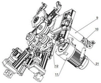
FIG. 1 is an exploded view of one embodiment of the present invention.
Fig. 2 is an exploded view of an embodiment of the present invention.
Fig. 3 is an exploded view of an embodiment of the present invention.
Fig. 4 is a schematic structural diagram of an embodiment of the present invention.
FIG. 5 is a schematic structural diagram of an embodiment of the present invention
Fig. 6 is a perspective view of an embodiment of the present invention.
Description of reference numerals: 1-a driving working roll; 2-unloading the working roll; 3-a pressurized working roll; 4-loading the working roll; 5-a pressurized servo motor; 6-loading the guide rail; 7-auxiliary rolling and bending sliding blocks on the right side; 8-right side springback compensation roller; 9-auxiliary roll bending sleeve on right side; 10-right side springback compensation working roll group; 11-drive roll servo motor; 12-a drive roll sleeve; 13-a support collar; 14-left rebound compensation roller; 15-left auxiliary roll bending slide block; 16-right side auxiliary roll bending guide rail; 17-auxiliary right roll bending fixed supporting plate; 18-left auxiliary roll bending fixed support plate; 19-left auxiliary roll bending guide rail; 20-left side springback compensation work roll group; 21-right auxiliary roll bending hydraulic rod; 22-left auxiliary roll bending hydraulic rod; 23-right servo motor, 24-left servo motor; 25-right auxiliary roll bending servo motor, 26-right auxiliary roll bending ball screw; 27-left auxiliary roll bending ball screw; 28-left side roll bending servo motor, 29-box shell, 30-lifting bolt, 31-frame heat dissipation plate and 32-support base; 33-a torsion motor, 34-a coupler, 35-a torsion end cover, 36-a torsion box body, 37-a fixture block, 38-a worm and 39-a worm wheel.
Detailed Description
The present invention will be further described with reference to the following examples.
Referring to fig. 1, the horizontal numerical control rounding machine of the invention comprises a frame, a work roll set and a numerical control system; the center of the upper surface of the rack is provided with a driving working roll 1, the driving working roll 1 is driven by a driving roll servo motor 11 to work, the left side and the right side of the driving working roll 1 are provided with an unloading working roll 2 and a loading working roll 4, and a pressurizing working roll 3 is arranged between the unloading working roll 2 and the loading working roll 4; the position of the driving working roll 1 is selected at the center of the upper surface of the frame, a driving roll sleeve 12 provided with the driving working roll 1 is locked by a bolt, so that the position of the driving roll sleeve is not movable, and the driving working roll 1 rotates to work.
The loading working roll 4 is arranged on the right side of the driving working roll 1, the loading working roll 4 is arranged on the lantern ring, the lantern ring is installed on the loading guide rail 6, the loading working roll 4 is connected with the right servo motor 23 through the lantern ring, and the right servo motor 23 drives the loading working roll 4 to move along the loading guide rail 6 to be close to or far away from the driving working roll 1 to adjust the position.
The pressurizing working roll 3 is arranged on the supporting sleeve ring 13 and is hinged with the pressurizing working roll supporting shaft through the supporting sleeve ring 13, the pressurizing servo motor 5 drives the supporting sleeve ring 13 to rotate around the pressurizing working roll supporting shaft to drive the pressurizing working roll 3 to be close to or far away from the driving working roll 1, and the pressurizing working roll supporting shaft is arranged inside the rack.
The upper surface of the rack is provided with a driving working roll seat platform, a loading working roll supporting wall plate and an unloading working roll supporting wall plate, the driving working roll seat platform is connected with and provided with a driving working roll 1, the loading working roll supporting wall plate and the unloading working roll supporting wall plate are arranged in a splayed manner, a pressure roll installation area is arranged between the loading working roll supporting wall plate and the unloading working roll supporting wall plate, the loading working roll supporting wall plate is arranged on one side of the driving working roll seat platform, the loading working roll supporting wall plates are arranged at intervals, loading guide rails 6 are arranged on the inner side walls, opposite to the two unloading working roll supporting wall plates, of the two unloading working roll supporting wall plates which are arranged at intervals, and the loading guide rails 6 are used for connecting and arranging loading working rolls 4; the unloading working roll supporting wall plate is arranged at the position of the other side of the working table plate 1, which is symmetrical to the loading working roll supporting wall plate, and the arrangement mode of the unloading working roll supporting wall plate is the same as that of the unloading working roll supporting wall plate; the loading working roll supporting wall plate, the unloading working roll supporting wall plate and the driving working roll seat stand are integrally formed.
The right side springback compensation idler wheel 8 and the right side auxiliary roll bending fixed supporting plate 17 are arranged on the right side springback compensation working roller group 10, and the right side springback compensation idler wheel 8 and the right side auxiliary roll bending fixed supporting plate 17 are arranged on the right side auxiliary roll bending sliding block 7; the right auxiliary roll bending servo motor 25 drives a right auxiliary roll bending ball screw 26, the right auxiliary roll bending ball screw 26 drives a right auxiliary roll bending slide block 7, and the right auxiliary roll bending slide block 7 drives a right springback compensation roller 8 and a right auxiliary roll bending fixed support plate 17 to move to change positions; the right side resilience compensation roller work roll set sets up on the back shaft, and the supplementary curved hydraulic stem 21 drive back shaft rotation of rolling in right side, and the top of back shaft is connected with the frame through the supplementary curved sleeve 9 that rolls in right side, and the back shaft rotation drives the supplementary curved fixed stay board 17 of rolling in right side resilience compensation gyro wheel 8, right side and rotates the adjusting position along with the back shaft rotation. The work can be in the needs of different positions when satisfying different section bars, different processing angles, and during the adjusting position, the circle at the 8 contact points of right side springback compensation gyro wheel all adjusts into tangent line contact with the work piece of processing.
The left springback compensation work roll group 20 is provided with a left springback compensation roller 14, a left auxiliary roll bending slider 15, a left auxiliary roll bending fixed support plate 18, a left auxiliary roll bending guide rail 19, a left auxiliary roll bending hydraulic rod 22, a left auxiliary roll bending ball screw 27 and a left roll bending servo motor 28. The left rebound compensation work roll group 20 and the right rebound compensation work roll group 10 have the same structure and the same working principle.
The side wall plate of the case body shell 29 is a rack heat dissipation plate 31 which is provided with heat dissipation holes for facilitating heat dissipation; two lifting ring screws 30 which are arranged at intervals are arranged on the box body shell 29, so that the connection and the fixation are convenient. A support base 32 is provided on the bottom surface of the box casing 29, and the support base 32 supports the box casing 29.
A torsion device is arranged above the left roll bending slide block 15 and consists of a torsion motor 33, a coupler 34, a torsion end cover 35, a torsion box body 36, a fixture block 37, a worm 38 and a worm wheel 39; the rotating motor 33 drives the worm 38 through the coupler 34, the worm 38 drives the worm wheel 39 to rotate, a fixture block 37 is arranged at the center of the worm wheel 39, a twisting hole is formed between the fixture blocks 37, a processed workpiece is inserted into the twisting hole and limited by the fixture block 37, the worm 38 and the worm wheel 39 are arranged in the twisting box 36, a twisting end cover 35 is arranged on one side of the twisting box 36, and the twisting end cover 35 is connected and fixed with the rotating motor 33.
The torsion device is installed on the left side roll bending slide block 15, the motion mode of the left side roll bending slide block 15 is the same as the motion principle and mode of the right side roll bending slide block 7, the torsion device can move along with the motion of the left side roll bending slide block 15, and therefore the working position is changed, and the linkage provides a more comprehensive processing mode for the torsion device.
The working principle and the working process of the device are as follows:
when the horizontal numerical control rounding machine works, related codes are required to be input into a numerical control system interface, after action simulation is carried out to confirm that no errors exist, the rounding machine is started, materials to be processed are placed on a workbench, and auxiliary fixtures are used for being placed in a working gap formed by the driving working roll 1, the unloading working roll 2, the loading working roll 4 and the pressurizing working roll 3. During machining, the feed amounts of the left servo motor 24, the right servo motor 23 and the lower pressurizing servo motor 5 are controlled by the terminal of the numerical control system to adjust the working clearance in the fourth roller forming mechanism, and the driving working roller 1 rotates to drive the feeding of the material, so that the preliminary machining of the formed material is automatically finished. Due to the resilient properties of the material, compensation of the resilience of the profile is particularly important. Since the left and right mechanisms are the same and the adjustment method is the same, the right mechanism is taken as an example for adjustment. The numerical control system controls the servo motor 25 to control the right auxiliary roll bending slide block 7 to move along the right auxiliary roll bending guide rail 16, and the whole auxiliary roll bending device can rotate around the central shaft of the right auxiliary roll bending power output device 9. So the position of the right springback compensation roller 8 can be adjusted according to the requirement, and the right springback compensation roller 8 can complete the springback compensation of the section bar at the correct position.
When the twisting device works, when a material passes through the inlet of the twisting device, the clamping block 37 locks the material, then the twisting motor 33 is started, the worm 38 is driven by the coupler 34 to rotate, meanwhile, the worm wheel 39 is driven by the worm to rotate, and the material is subjected to twisting deformation under the action of the clamping block 37 and the worm wheel 39. The above arrangement allows the present embodiment to have a twisting function in addition to the bending function.
Claims (7)
1. The utility model provides a horizontal numerical control rounding machine, includes the frame, work roller set, numerical control system, its characterized in that:
the center of the upper surface of the rack is provided with a driving working roll (1), the left side and the right side of the driving working roll (1) are provided with an unloading working roll (2) and a loading working roll (4), and a pressurizing working roll (3) is arranged between the unloading working roll (2) and the loading working roll (4);
the position of the driving working roll (1) is fixed; the loading working roll (4) is arranged on the right side of the driving working roll (1), and the right hydraulic rod (23) drives the loading working roll (4) to be close to or far away from the driving working roll (1) for position adjustment; the unloading working roll (2) is arranged on the left side of the driving working roll (1), and a left servo motor (24) drives the unloading working roll (2) to be close to or far away from the driving working roll (1) for position adjustment; the pressurizing working roll (3) is driven by a pressurizing servo motor (5) to be close to or far away from the driving working roll (1) to carry out position adjustment; the outsides of the unloading working roll (2) and the loading working roll (4) are provided with a springback compensation working roll set, and the springback compensation working roll set is provided with a left springback compensation working roll set and a right springback compensation working roll set;
the upper surface of the rack is provided with a driving working roll seat platform, a loading working roll supporting wall plate and an unloading working roll supporting wall plate, the driving working roll seat platform is connected with and provided with a driving working roll (1), the loading working roll supporting wall plate and the unloading working roll supporting wall plate are arranged in a splayed manner, a pressure roll installation area is arranged between the loading working roll supporting wall plate and the unloading working roll supporting wall plate, the loading working roll supporting wall plate is arranged on one side of the driving working roll seat platform, the loading working roll supporting wall plates are arranged at intervals, loading guide rails (6) are arranged on the inner side walls, opposite to the two unloading working roll supporting wall plates, of the two unloading working roll supporting wall plates which are arranged at intervals, and the loading guide rails (6) are used for connecting and arranging loading working rolls (4); the unloading working roll supporting wall plate is arranged at the position of the other side of the working table plate (1) which is symmetrical to the loading working roll supporting wall plate, and the arrangement mode of the unloading working roll supporting wall plate is the same as that of the unloading working roll supporting wall plate; the loading working roll supporting wall plate, the unloading working roll supporting wall plate and the driving working roll seat stand are integrally formed;
the right springback compensation working roll set is provided with a right springback compensation roller (8) and a right auxiliary roll bending fixed supporting plate (17), the right springback compensation roller (8) is arranged at the right auxiliary roll bending fixed supporting plate (17), the axes of the right auxiliary roll bending fixed supporting plate (17) and the right springback compensation roller (8) are vertically arranged, the right springback compensation roller (8) is arranged right above the right auxiliary roll bending fixed supporting plate (17), and the right springback compensation roller (8) tightly pushes a machined workpiece to prevent the machined workpiece from springback deformation; the left springback compensation working roller set and the right springback compensation working roller set are identical in structure and working principle.
2. The horizontal numerical control rounding machine according to claim 1, characterized in that: the loading working roller (4) is arranged on the lantern ring, the lantern ring is arranged on the loading guide rail (6), the loading working roller (4) is connected with the right servo motor (23) through the lantern ring, and the right servo motor (23) drives the loading working roller (4) to move close to or far away from the driving working roller (1) along the loading guide rail (6) to adjust the position; the arrangement mode of the unloading working roll (2) and the loading working roll (4).
3. The horizontal numerical control rounding machine according to claim 1, characterized in that: the right springback compensation roller (8) and the right auxiliary roll bending fixed supporting plate (17) are both arranged on the right auxiliary roll bending sliding block (7); the right auxiliary roll bending servo motor (25) drives a right auxiliary roll bending ball screw (26), the right auxiliary roll bending ball screw (26) drives a right auxiliary roll bending sliding block (7), and the right auxiliary roll bending sliding block (7) drives a right springback compensation roller (8) and a right auxiliary roll bending fixed supporting plate (17) to move to change positions; the right springback compensation roller working roller set is arranged on the supporting shaft, the right auxiliary roll bending hydraulic rod (21) drives the supporting shaft to rotate, and the supporting shaft rotates to drive the right springback compensation roller (8) and the right auxiliary roll bending fixed supporting plate (17) to rotate and adjust the position along with the rotation of the supporting shaft.
4. The horizontal numerical control rounding machine according to claim 1, characterized in that: the rack is also provided with a twisting device, and the twisting device is provided with a twisting motor (33), a coupler (34), a clamping block (37), a worm (38) and a worm wheel (39); the rotating motor (33) drives the worm (38) through the coupler (34), the worm (38) drives the worm wheel (39) to rotate, the center of the worm wheel (39) is provided with clamping blocks (37), twisting holes are formed among the clamping blocks (37), and a workpiece to be processed is inserted into the twisting holes and then limited by the clamping blocks (37).
5. The horizontal numerical control rounding machine according to claim 4, characterized in that: the torsion device is further provided with a torsion box body (36) and a torsion end cover (35), the worm (38) and the worm wheel (39) are arranged in the torsion box body (36), the torsion end cover (35) is arranged on one side of the torsion box body (36), and the torsion end cover (35) is connected and fixed with the torsion motor (33).
6. The horizontal numerical control rounding machine according to claim 4, characterized in that: the torsion device is arranged on the left roll bending slide block (15).
7. The horizontal numerical control rounding machine according to claim 1, characterized in that: the pressurizing working roll (3) is arranged on the supporting sleeve ring (13) and is hinged with the pressurizing working roll supporting shaft through the supporting sleeve ring (13), the pressurizing servo motor (5) drives the supporting sleeve ring (13) to rotate around the pressurizing working roll supporting shaft to drive the pressurizing working roll (3) to be close to or far away from the driving working roll (1), and the pressurizing working roll supporting shaft is arranged inside the rack.
Priority Applications (2)
| Application Number | Priority Date | Filing Date | Title |
|---|---|---|---|
| CN202211216227.0A CN115532907A (en) | 2022-10-01 | 2022-10-01 | Horizontal numerical control rounding machine |
| GB2300270.2A GB2622896A (en) | 2022-10-01 | 2023-01-09 | Horizontal numerical control round bending machine |
Applications Claiming Priority (1)
| Application Number | Priority Date | Filing Date | Title |
|---|---|---|---|
| CN202211216227.0A CN115532907A (en) | 2022-10-01 | 2022-10-01 | Horizontal numerical control rounding machine |
Publications (1)
| Publication Number | Publication Date |
|---|---|
| CN115532907A true CN115532907A (en) | 2022-12-30 |
Family
ID=84731089
Family Applications (1)
| Application Number | Title | Priority Date | Filing Date |
|---|---|---|---|
| CN202211216227.0A Pending CN115532907A (en) | 2022-10-01 | 2022-10-01 | Horizontal numerical control rounding machine |
Country Status (2)
| Country | Link |
|---|---|
| CN (1) | CN115532907A (en) |
| GB (1) | GB2622896A (en) |
Cited By (1)
| Publication number | Priority date | Publication date | Assignee | Title |
|---|---|---|---|---|
| GB2622896A (en) * | 2022-10-01 | 2024-04-03 | Univ Liaocheng | Horizontal numerical control round bending machine |
Family Cites Families (2)
| Publication number | Priority date | Publication date | Assignee | Title |
|---|---|---|---|---|
| CN216027307U (en) * | 2021-08-23 | 2022-03-15 | 杭州富阳江通木业有限公司 | Clamping device of pipe bender |
| CN115532907A (en) * | 2022-10-01 | 2022-12-30 | 聊城大学 | Horizontal numerical control rounding machine |
-
2022
- 2022-10-01 CN CN202211216227.0A patent/CN115532907A/en active Pending
-
2023
- 2023-01-09 GB GB2300270.2A patent/GB2622896A/en active Pending
Cited By (1)
| Publication number | Priority date | Publication date | Assignee | Title |
|---|---|---|---|---|
| GB2622896A (en) * | 2022-10-01 | 2024-04-03 | Univ Liaocheng | Horizontal numerical control round bending machine |
Also Published As
| Publication number | Publication date |
|---|---|
| GB2622896A (en) | 2024-04-03 |
Similar Documents
| Publication | Publication Date | Title |
|---|---|---|
| CN102320210B (en) | Cylindrical engraving machine | |
| US4766752A (en) | Machine tool for the production of tubular components | |
| CN101745905A (en) | Multi-degree of freedom adjustable assembling platform used for butt joint of aircraft wings | |
| CN1223417C (en) | Method of rolling worm gear and worm gear | |
| CN115532907A (en) | Horizontal numerical control rounding machine | |
| CN201320670Y (en) | Assembly platform | |
| CN114932155B (en) | Reshaping device for vehicle door remanufacturing | |
| CN103084444B (en) | Roll changing device of cold roll forming quick-changing rack | |
| CN111958710A (en) | Woodworking processing center | |
| CN107262566B (en) | Numerical control reverse winding curved variable-diameter flexible roll bending forming machine | |
| CN113442044A (en) | Finish machining device for die steel | |
| CN101745764A (en) | Welding fabrication equipment for variable cross-section I-shaped beam | |
| CN103372796B (en) | Caliber pipe inwall finishing machine and bistrique | |
| CN115716137A (en) | Gollin column turning machine tool | |
| CN211071399U (en) | Automatic compensation mechanism for 3-piece matching wedge block bidirectional multipoint deflection of large bending machine | |
| CN109772964B (en) | Pipe bending device and application method thereof | |
| CN209736478U (en) | automatic pipe expander with multiple degrees of freedom | |
| CN220387943U (en) | Radial drilling machine with external feed hydraulic pump | |
| CN112393988A (en) | Novel device for thin strip tension bending experiment | |
| CN1229193C (en) | United corner jointing machine | |
| CN104368917A (en) | Spiral weld-pipe mill | |
| CN219188660U (en) | Rod piece processing device with multidirectional support | |
| CN214184979U (en) | Auxiliary supporting wheel mechanism | |
| CN217371792U (en) | Aluminum pipe wire drawing machine | |
| CN217316955U (en) | Be used for thin wall casing production adds clamping apparatus |
Legal Events
| Date | Code | Title | Description |
|---|---|---|---|
| PB01 | Publication | ||
| PB01 | Publication | ||
| SE01 | Entry into force of request for substantive examination | ||
| SE01 | Entry into force of request for substantive examination |