CN115516902A - Method, device and equipment for recovering failure of side-link SL beam and storage medium - Google Patents
Method, device and equipment for recovering failure of side-link SL beam and storage medium Download PDFInfo
- Publication number
- CN115516902A CN115516902A CN202280002563.7A CN202280002563A CN115516902A CN 115516902 A CN115516902 A CN 115516902A CN 202280002563 A CN202280002563 A CN 202280002563A CN 115516902 A CN115516902 A CN 115516902A
- Authority
- CN
- China
- Prior art keywords
- terminal device
- configuration information
- recovery
- bfd
- configuration
- Prior art date
- Legal status (The legal status is an assumption and is not a legal conclusion. Google has not performed a legal analysis and makes no representation as to the accuracy of the status listed.)
- Pending
Links
Images


Classifications
-
- H—ELECTRICITY
- H04—ELECTRIC COMMUNICATION TECHNIQUE
- H04W—WIRELESS COMMUNICATION NETWORKS
- H04W24/00—Supervisory, monitoring or testing arrangements
- H04W24/04—Arrangements for maintaining operational condition
-
- H—ELECTRICITY
- H04—ELECTRIC COMMUNICATION TECHNIQUE
- H04L—TRANSMISSION OF DIGITAL INFORMATION, e.g. TELEGRAPHIC COMMUNICATION
- H04L5/00—Arrangements affording multiple use of the transmission path
- H04L5/0091—Signaling for the administration of the divided path
- H04L5/0096—Indication of changes in allocation
- H04L5/0098—Signalling of the activation or deactivation of component carriers, subcarriers or frequency bands
-
- H—ELECTRICITY
- H04—ELECTRIC COMMUNICATION TECHNIQUE
- H04W—WIRELESS COMMUNICATION NETWORKS
- H04W72/00—Local resource management
- H04W72/04—Wireless resource allocation
- H04W72/044—Wireless resource allocation based on the type of the allocated resource
- H04W72/046—Wireless resource allocation based on the type of the allocated resource the resource being in the space domain, e.g. beams
Landscapes
- Engineering & Computer Science (AREA)
- Signal Processing (AREA)
- Computer Networks & Wireless Communication (AREA)
- Mobile Radio Communication Systems (AREA)
Abstract
The present disclosure provides a SL beam failure recovery method, apparatus, device, and storage medium, the method comprising: determining configuration information, the configuration information comprising at least one of: at least one first indication information for indicating a SL beam between a first terminal device and a second terminal device, the second terminal device communicating with the first terminal device through a SL; at least one SL wave beam corresponds to a carried side link wave beam failure detection reference signal SL-BFD-RS; at least one first configuration for performing sidelink beam failure detection, SL-BFD; at least one second configuration for performing SL-BFR for sidelink beam failure recovery; triggering an SL beam failure recovery procedure in response to determining that the SL beam fails based on the configuration information. The embodiment of the disclosure provides a method for recovering SL beam failure between SL direct-connected terminal devices, so that SL transmission can support beam failure recovery.
Description
Technical Field
The present disclosure relates to the field of communications technologies, and in particular, to a SL beam failure recovery method, apparatus, device, and storage medium.
Background
In a communication system, a Sidelink (SL) communication scheme is introduced to realize direct communication between terminal devices. Meanwhile, in a communication system, devices usually communicate with each other on a beam basis, so as to increase a data transmission rate and reduce interference.
In the related art, when a beam failure occurs between devices, a beam recovery procedure is usually triggered to recover the beam.
However, currently, no specific beam failure recovery procedure has been introduced for SL transmission, so that the SL transmission currently does not support beam failure recovery.
Disclosure of Invention
The present disclosure provides a method, an apparatus, a device and a storage medium for recovering a SL beam failure, so as to solve the technical problem that the SL transmission in the related art does not support the beam failure recovery.
In a first aspect, an embodiment of the present disclosure provides a SL beam failure recovery method, where the method is performed by a first terminal device, and includes:
determining configuration information, the configuration information including at least one of:
at least one first indication information for indicating a SL beam between a first terminal device and a second terminal device, the second terminal device communicating with the first terminal device through a SL;
at least one SL wave beam corresponds to a carried side link wave beam failure detection reference signal SL-BFD-RS;
at least one first configuration for performing sidelink beam failure detection, SL-BFD;
at least one second configuration for performing a sidelink beam failure recovery, SL-BFR;
triggering an SL beam failure recovery procedure in response to determining that the SL beam fails based on the configuration information.
In the present disclosure, a method for recovering a failure of an SL beam is provided, where a first terminal device determines configuration information, where the configuration information includes at least one of: at least one first indication information for indicating an SL beam between a first terminal device and a second terminal device, wherein the second terminal device communicates with the first terminal device through SL; at least one SL wave beam corresponds to the carried SL-BFD-RS; at least one first configuration for SL-BFD; at least one second configuration for SL-BFR. And when the first terminal equipment determines that the SL beam fails based on the configuration information, the first terminal equipment triggers an SL beam failure recovery process. Therefore, in the embodiment of the present disclosure, when the first terminal device communicates with the second terminal device through the SL beam, it is specifically determined whether the SL beam failure occurs based on the configuration information determined by the first terminal device, and when it is determined that the SL beam failure occurs, the SL beam failure recovery process is triggered to perform beam recovery.
Optionally, the determining the SL beam failure based on the configuration information includes:
measuring the SL-BFD-RS and determining whether the frequency of the BF occurrence of the wave beam failure meets a preset condition;
and determining that the SL beam fails in response to determining that the number of BF occurrences satisfies a preset condition.
Optionally, the first indication information is a transmission configuration indication TCI corresponding to the SL beam.
Optionally, the first configuration includes at least one of:
presetting time length;
a first threshold value;
wherein the first threshold is used for: and when the BF occurrence frequency reaches the first threshold value, or when the BF occurrence frequency reaches the first threshold value in the preset time length, determining that the SL wave beam fails to occur.
Optionally, the second configuration includes at least one of:
an identification of at least one candidate recovery beam;
at least one candidate recovery beam corresponds to the carried reference signal;
a second threshold value for beam recovery.
Optionally, different SL-BFD-RSs correspond to different first configurations; and/or the presence of a gas in the gas,
the different SL-BFD-RSs correspond to a different second configuration.
Optionally, the determining the configuration information includes at least one of:
receiving the configuration information sent by the network equipment;
and receiving the configuration information sent by the second terminal equipment.
Optionally, the measuring the SL-BFD-RS and determining whether the number of BF occurrences satisfies a preset condition includes:
detecting whether BF occurs in the process of measuring the SL-BFD-RS;
counting the BF occurrence frequency;
and determining that the preset condition is met in response to the BF occurrence frequency reaching the first threshold value.
Optionally, the measuring the SL-BFD-RS and determining whether the number of BF occurrences satisfies a preset condition includes:
in the process of measuring the SL-BFD-RS, responding to the initial generation of BF, starting a timer, wherein the timing duration of the timer is the preset duration;
counting the BF occurrence frequency;
and responding to the starting period of the timer, determining that the BF occurrence times reach the first threshold value, and determining that the preset condition is met.
Optionally, the method further includes:
and in response to the timer being out of time, setting a count value of the number of BF occurrences to zero.
Optionally, the method further includes:
and obtaining a measurement result, wherein the measurement result is obtained by measuring a reference signal carried by the candidate recovery beam correspondingly.
Optionally, the triggering of the SL beam failure recovery process includes:
sending a SL-BFR indication to a second terminal device;
the SL-BFR indication includes at least one of:
the BF occurrence frequency meets the SL-BFD-RS identification of the preset condition;
an identification of candidate recovery beams for which measurements exist;
an identification of candidate recovery beams having a measurement result higher than a second threshold value;
identification of the candidate recovery beam with the best measurement result;
a measurement corresponding to a candidate recovery beam and an identification of the candidate recovery beam.
Optionally, the triggering of the SL beam failure recovery process includes:
receiving a beam activation indication sent by the second terminal device, wherein the beam activation indication comprises an identifier of an activated candidate recovery beam;
determining an activated candidate recovery beam based on the beam activation indication;
communicating with a second terminal device based on the activated candidate recovery beam.
Optionally, the measurement result includes at least one of:
reference signal received power, RSRP;
reference signal received quality SINR.
In a second aspect, an embodiment of the present disclosure provides a SL beam failure recovery method, where the method is performed by a second terminal device, and includes:
determining configuration information; the configuration information includes at least one of:
at least one piece of first indication information for indicating a SL beam between a first terminal device and a second terminal device, wherein the second terminal device communicates with the first terminal device through SL;
at least one SL wave beam corresponds to the carried SL-BFD-RS;
at least one first configuration for SL-BFD;
at least one second configuration for SL-BFR.
Optionally, the determining the configuration information includes:
receiving configuration information sent by network equipment; or
And receiving the configuration information sent by the network equipment and the identification of the first terminal equipment applicable to the configuration information.
Optionally, the first indication information is a transmission configuration indication TCI corresponding to the SL beam.
Optionally, the first configuration includes at least one of:
presetting time length;
a first threshold value;
wherein the first threshold value is used for: and when the measured BF occurrence frequency reaches the first threshold value, or when the measured BF occurrence frequency reaches the first threshold value in the preset time length, determining that the SL wave beam failure occurs.
Optionally, the second configuration includes at least one of:
an identification of at least one candidate recovery beam;
at least one candidate recovery beam corresponds to the carried reference signal;
a second threshold value for beam recovery.
Optionally, different SL-BFD-RSs correspond to different first configurations; and/or the presence of a gas in the gas,
the different SL-BFD-RS corresponds to a different second configuration.
Optionally, the method further includes:
and sending the configuration information to the first terminal equipment.
Optionally, the sending the configuration information to the first terminal device includes:
and responding to the network equipment sending the identifier of the first terminal equipment applicable to the configuration information to the second terminal equipment, and sending the configuration information to the first terminal equipment corresponding to the identifier.
Optionally, the method further includes:
receiving a SL-BFR instruction sent by first terminal equipment;
the SL-BFR indication includes at least one of:
the BF occurrence frequency meets the SL-BFD-RS identification of the preset condition;
an identification of candidate recovery beams for which measurements exist;
an identification of candidate recovery beams having a measurement result above a second threshold;
identification of the candidate recovery beam with the best measurement result;
a measurement corresponding to a candidate recovery beam and an identification of the candidate recovery beam.
Optionally, the method further includes:
the second terminal device autonomously determines a candidate recovery beam to activate.
Optionally, in response to that the second terminal device is in a connected state, and/or that the second terminal device allocates SL transmission resources based on dynamic scheduling of a network device, the method further includes:
sending second indication information to the network equipment; the second indication information includes at least one of:
the identifier corresponding to the first terminal device;
an identity of an activated candidate recovery beam autonomously determined by the second terminal device;
a measurement corresponding to the activated candidate recovery beam.
Optionally, in response to that the second terminal device is in a connected state, and/or that the second terminal device allocates SL transmission resources based on dynamic scheduling of a network device, the method further includes:
sending third indication information to the network device, where the third indication information includes at least one of:
the SL-BFR indication;
and the SL-BFR indicates the identification of the corresponding first terminal equipment.
Optionally, the method further includes:
and acquiring activated beam information sent by the network equipment, wherein the activated beam information comprises the identification of the activated candidate recovery beam.
Optionally, the method further includes:
sending a beam activation indication to the first terminal device, wherein the beam activation indication comprises an identifier of an activated candidate recovery beam;
communicating with a first terminal device based on the activated candidate recovery beam.
In a third aspect, an embodiment of the present disclosure provides a SL beam failure recovery method, where the method is performed by a network device, and includes:
sending configuration information to a first terminal device, wherein the configuration information comprises at least one of the following:
at least one piece of first indication information used for indicating SL wave beams between a first terminal device and a second terminal device, wherein the second terminal device is communicated with the first terminal device through SL;
at least one SL beam correspondingly bears a sidelink beam failure detection reference signal SL-BFD-RS;
at least one first configuration for performing sidelink beam failure detection, SL-BFD;
at least one second configuration to perform sidelink beam failure recovery, SL-BFR.
Optionally, the first indication information is a transmission configuration indication TCI corresponding to the SL beam.
Optionally, the first configuration includes at least one of:
presetting time length;
a first threshold value;
wherein the first threshold value is used for: and when the BF occurrence frequency reaches the first threshold value, or when the BF occurrence frequency reaches the first threshold value in the preset time length, determining that the SL wave beam fails to occur.
Optionally, the second configuration includes at least one of:
an identification of at least one candidate recovery beam;
at least one candidate recovery beam corresponds to the carried reference signal;
a second threshold value for beam recovery.
Optionally, different SL-BFD-RSs correspond to different first configurations; and/or the presence of a gas in the atmosphere,
the different SL-BFD-RSs correspond to a different second configuration.
Optionally, the method further includes:
and sending configuration information and/or an identifier of the first terminal equipment applicable to the configuration information to the second terminal equipment.
Optionally, the method further includes:
receiving second indication information sent by the second terminal equipment; the second indication information includes at least one of:
the identifier corresponding to the first terminal device;
an identity of an activated candidate recovery beam autonomously determined by the second terminal device;
a measurement corresponding to the activated candidate recovery beam.
Optionally, the method further includes:
receiving third indication information sent by the second terminal device, where the third indication information includes at least one of the following:
the SL-BFR indication;
the SL-BFR indicates the identification of the corresponding first terminal equipment;
wherein the SL-BFR indication comprises at least one of:
the BF occurrence frequency meets the SL-BFD-RS identification of the preset condition;
an identification of candidate recovery beams for which measurements exist;
an identification of candidate recovery beams having a measurement result above a second threshold;
identification of the candidate recovery beam with the best measurement result;
a measurement corresponding to a candidate recovery beam and an identification of the candidate recovery beam.
Optionally, the method further includes:
determining an activated candidate recovery beam;
and sending activated beam information to the second terminal equipment, wherein the activated beam information comprises the identification of the activated candidate recovery beam.
In a fourth aspect, an embodiment of the present disclosure provides a communication apparatus, where the apparatus is configured in a first terminal device, and includes:
a processing module configured to determine configuration information, the configuration information including at least one of:
at least one first indication information for indicating a SL beam between a first terminal device and a second terminal device, the second terminal device communicating with the first terminal device through a SL;
at least one SL wave beam corresponds to a carried side link wave beam failure detection reference signal SL-BFD-RS;
at least one first configuration for performing sidelink beam failure detection, SL-BFD;
at least one second configuration for performing SL-BFR for sidelink beam failure recovery;
the processing module is further configured to trigger an SL beam failure recovery procedure in response to determining that the SL beam failed based on the configuration information.
In a fifth aspect, an embodiment of the present disclosure provides a communication apparatus, where the apparatus is configured in a second terminal device, and includes:
a transceiver module, configured to receive a SL-BFR indication sent by a first terminal device, where the second terminal device communicates with the first terminal device through a SL;
the SL-BFR indication includes at least one of:
the BF occurrence frequency meets the SL-BFD-RS identification of the preset condition;
an identification of candidate recovery beams for which measurements exist;
an identification of candidate recovery beams having a measurement result above a second threshold;
identification of the candidate recovery beam with the best measurement result;
a measurement corresponding to a candidate recovery beam and an identification of the candidate recovery beam.
In a sixth aspect, an embodiment of the present disclosure provides a communication apparatus, configured in a network device, including:
a transceiver module, configured to send configuration information to a first terminal device, where the configuration information includes at least one of:
at least one first indication information for indicating a SL beam between a first terminal device and a second terminal device, the second terminal device communicating with the first terminal device through a SL;
at least one SL beam correspondingly bears a sidelink beam failure detection reference signal SL-BFD-RS;
at least one first configuration for performing sidelink beam failure detection, SL-BFD;
at least one second configuration to perform SL-BFR for sidelink beam failure recovery.
In a seventh aspect, an embodiment of the present disclosure provides a communication apparatus, which includes a processor, and when the processor calls a computer program in a memory, the processor executes the method according to the first aspect.
In an eighth aspect, embodiments of the present disclosure provide a communication device, which includes a processor, and when the processor calls a computer program in a memory, the processor executes the method of the second aspect.
In a ninth aspect, an embodiment of the present disclosure provides a communication apparatus, which includes a processor, and when the processor calls a computer program in a memory, executes the method of the third aspect.
In a tenth aspect, an embodiment of the present disclosure provides a communication apparatus, including a processor and a memory, where the memory stores a computer program; the processor executes the computer program stored in the memory to cause the communication device to perform the method of the first aspect.
In an eleventh aspect, embodiments of the present disclosure provide a communications apparatus that includes a processor and a memory, the memory having a computer program stored therein; the processor executes the computer program stored in the memory to cause the communication device to perform the method of the second aspect.
In a twelfth aspect, embodiments of the present disclosure provide a communication device comprising a processor and a memory, the memory having stored therein a computer program; the processor executes the computer program stored in the memory to cause the communication device to perform the method of the third aspect.
In a thirteenth aspect, the disclosed embodiments provide a communication device, the device includes a processor and an interface circuit, the interface circuit is configured to receive code instructions and transmit the code instructions to the processor, and the processor is configured to execute the code instructions to cause the device to perform the method of the first aspect.
In a fourteenth aspect, the disclosed embodiments provide a communications apparatus that includes a processor and an interface circuit configured to receive code instructions and transmit the code instructions to the processor, and the processor is configured to execute the code instructions to cause the apparatus to perform the method of the second aspect.
In a fifteenth aspect, the disclosed embodiments provide a communications device, the device comprising a processor and an interface circuit, the interface circuit being configured to receive code instructions and transmit the code instructions to the processor, and the processor being configured to execute the code instructions to cause the device to perform the method of the third aspect.
In a sixteenth aspect, the disclosed embodiments provide a communication system, which includes the communication apparatus of the fourth aspect to the communication apparatus of the sixth aspect, or the system includes the communication apparatus of the seventh aspect to the communication apparatus of the ninth aspect, or the system includes the communication apparatus of the tenth aspect to the communication apparatus of the twelfth aspect, or the system includes the communication apparatus of the thirteenth aspect to the communication apparatus of the fifteenth aspect.
In a seventeenth aspect, an embodiment of the present invention provides a computer-readable storage medium for storing instructions for the network device and/or the terminal device, where the instructions, when executed, cause the network device to perform the method of the first aspect, and/or cause the terminal device to perform the method of the second aspect, and/or cause the terminal device to perform the method of the third aspect.
In an eighteenth aspect, the present disclosure also provides a computer program product comprising a computer program which, when run on a computer, causes the computer to perform the method of any of the first to third aspects described above.
In a nineteenth aspect, the present disclosure provides a chip system, which includes at least one processor and an interface, and is configured to support a network device to implement the functions related to the methods in the first aspect, and/or support a terminal device to implement the functions related to the methods in the second aspect, and/or support a terminal device to implement the functions related to the methods in the third aspect, for example, to determine or process at least one of data and information related to the methods. In one possible design, the system-on-chip further includes a memory for storing computer programs and data necessary for the source secondary node. The chip system may be formed by a chip, or may include a chip and other discrete devices.
In a twentieth aspect, the present disclosure provides a computer program which, when run on a computer, causes the computer to perform the method of any one of the first to third aspects described above.
Drawings
The above and/or additional aspects and advantages of the present disclosure will become apparent and readily appreciated from the following description of the embodiments, taken in conjunction with the accompanying drawings of which:
fig. 1 is a schematic architecture diagram of a communication system according to an embodiment of the present disclosure;
fig. 2 is a schematic flow chart of SL beam failure recovery according to another embodiment of the present disclosure;
fig. 3 is a schematic flow chart of SL beam failure recovery according to an embodiment of the present disclosure;
fig. 4 is a schematic flow chart of SL beam failure recovery according to yet another embodiment of the present disclosure;
fig. 5 is an interaction diagram illustrating failure recovery of an SL beam according to an embodiment of the present disclosure;
fig. 6 is a schematic flow chart of SL beam failure recovery according to yet another embodiment of the present disclosure;
fig. 7 is a schematic flow chart of SL beam failure recovery according to yet another embodiment of the present disclosure;
fig. 8 is a schematic flow chart of SL beam failure recovery according to yet another embodiment of the present disclosure;
fig. 9 is a schematic flow chart of SL beam failure recovery according to yet another embodiment of the present disclosure;
fig. 10 is a schematic flow chart of SL beam failure recovery according to yet another embodiment of the present disclosure;
fig. 11 is a schematic flow chart of SL beam failure recovery according to yet another embodiment of the present disclosure;
fig. 12 is a schematic flow chart of SL beam failure recovery according to yet another embodiment of the present disclosure;
fig. 13 is a schematic flow chart of SL beam failure recovery according to yet another embodiment of the present disclosure;
fig. 14 is a schematic flow chart of SL beam failure recovery according to yet another embodiment of the present disclosure;
fig. 15 is a schematic flow chart of SL beam failure recovery according to yet another embodiment of the present disclosure;
fig. 16 is a schematic structural diagram of a communication device according to an embodiment of the present disclosure;
fig. 17 is a schematic structural diagram of a communication device according to another embodiment of the present disclosure;
fig. 18 is a schematic structural diagram of a communication device according to another embodiment of the present disclosure;
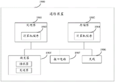
fig. 19 is a block diagram of a communication device provided by an embodiment of the present disclosure;
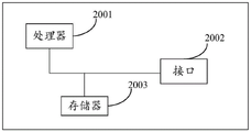
fig. 20 is a schematic structural diagram of a chip according to an embodiment of the disclosure.
Detailed Description
Reference will now be made in detail to the exemplary embodiments, examples of which are illustrated in the accompanying drawings. The following description refers to the accompanying drawings in which the same numbers in different drawings represent the same or similar elements unless otherwise indicated. The implementations described in the exemplary embodiments below are not intended to represent all implementations consistent with embodiments of the present disclosure. Rather, they are merely examples of apparatus and methods consistent with certain aspects of the embodiments of the disclosure, as detailed in the claims that follow.
The terminology used in the embodiments of the present disclosure is for the purpose of describing particular embodiments only and is not intended to be limiting of the embodiments of the present disclosure. As used in the disclosed embodiments and the appended claims, the singular forms "a," "an," and "the" are intended to include the plural forms as well, unless the context clearly indicates otherwise. It should also be understood that the term "and/or" as used herein refers to and encompasses any and all possible combinations of one or more of the associated listed items.
It is to be understood that although the terms first, second, third, etc. may be used herein to describe various information in the embodiments of the present disclosure, such information should not be limited by these terms. These terms are only used to distinguish one type of information from another. For example, first information may also be referred to as second information, and similarly, second information may also be referred to as first information, without departing from the scope of embodiments of the present disclosure. The words "if" and "if," as used herein, may be interpreted as "at" \8230; \8230when "or" when 8230; \823030, when "or" in response to a determination, "depending on the context.
Reference will now be made in detail to the embodiments of the present disclosure, examples of which are illustrated in the accompanying drawings, wherein like or similar reference numerals refer to the like or similar elements throughout. The embodiments described below with reference to the accompanying drawings are illustrative and intended to explain the present disclosure, and should not be construed as limiting the present disclosure.
For ease of understanding, terms referred to in the present application will be first introduced.
1. Sidelink (Sidelink, SL)
The sildelink communication is divided into two modes, one called discovery (discovery) between UEs, and the other called communication (communication) between UEs. Sidelink uses uplink resources and uplink physical channels similar to cellular networks (LTE) for data interactive transmission.
2. Radio Resource Control (RRC) signaling
The RRC signaling can provide a function of parameter configuration for a bottom layer protocol entity of the access network; and the mobile terminal is responsible for functions such as measurement and control related to the mobility management of the terminal equipment.
In order to better understand the method for determining the sidelink duration disclosed in the embodiment of the present application, a communication system to which the embodiment of the present application is applicable is first described below.
Referring to fig. 1, fig. 1 is a schematic diagram of an architecture of a communication system according to an embodiment of the present disclosure. The communication system may include, but is not limited to, a network device, a first terminal device and a second terminal device, wherein the first terminal device and the second terminal device communicate via SL, the number and the form of the devices shown in fig. 1 are only for example and do not constitute a limitation to the embodiments of the present disclosure, and two or more network devices and two or more terminal devices may be included in practical applications. The communication system shown in fig. 1 includes a network device 11, a first terminal device 12, and a second terminal device 13 as an example.
It should be noted that the technical solutions of the embodiments of the present disclosure can be applied to various communication systems. For example: a Long Term Evolution (LTE) system, a fifth generation (5 th generation, 5G) mobile communication system, a 5G New Radio (NR) system, or other future new mobile communication systems.
The network device 11 in the embodiment of the present disclosure is an entity for transmitting or receiving signals on the network side. For example, the network device 11 may be an evolved NodeB (eNB), a Transmission Reception Point (TRP), a next generation base station (gNB) in an NR system, a base station in another future mobile communication system, or an access node in a wireless fidelity (WiFi) system. The embodiments of the present disclosure do not limit the specific technologies and the specific device forms adopted by the network devices. The network device provided by the embodiment of the present disclosure may be composed of a Central Unit (CU) and a Distributed Unit (DU), where the CU may also be referred to as a control unit (control unit), and a protocol layer of a network device, such as a base station, may be split by using a structure of CU-DU, functions of a part of the protocol layer are placed in the CU for centralized control, and functions of the remaining part or all of the protocol layer are distributed in the DU, and the DU is centrally controlled by the CU.
The first terminal device 12 and the second terminal device 13 in the embodiment of the present disclosure may be an entity for receiving or transmitting signals, such as a mobile phone, on the user side. A terminal device may also be referred to as a terminal device (terminal), a User Equipment (UE), a Mobile Station (MS), a mobile terminal device (MT), etc. The terminal device may be an automobile with a communication function, a smart automobile, a mobile phone (mobile phone), a wearable device, a tablet computer (Pad), a computer with a wireless transceiving function, a Virtual Reality (VR) terminal device, an Augmented Reality (AR) terminal device, a wireless terminal device in industrial control (industrial control), a wireless terminal device in unmanned driving (self-driving), a wireless terminal device in remote surgery (remote medical supply), a wireless terminal device in smart grid (smart grid), a wireless terminal device in transportation safety (transportation safety), a wireless terminal device in smart city (smart city), a wireless terminal device in smart home (smart home), and the like. The embodiments of the present disclosure do not limit the specific technology and the specific device form adopted by the terminal device.
It is to be understood that the communication system described in the embodiment of the present disclosure is for more clearly illustrating the technical solutions of the embodiment of the present disclosure, and does not constitute a limitation to the technical solutions provided in the embodiment of the present disclosure, and as a person having ordinary skill in the art knows, with the evolution of the system architecture and the appearance of a new service scenario, the technical solutions provided in the embodiment of the present disclosure are also applicable to similar technical problems.
Also, in embodiments of the present disclosure, reference to "obtaining from" or "obtaining from" may be understood to mean "receiving from" or "receiving from.
Also, in the embodiments of the present disclosure, references to "based on" are to be understood as "based on" or "considering".
SL beam failure recovery, apparatus, devices, and storage media provided by embodiments of the present disclosure are described in detail below with reference to the accompanying drawings.
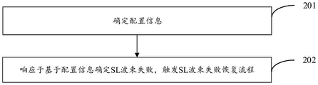
Fig. 2 is a schematic flowchart of a failure recovery process of an SL beam according to an embodiment of the present disclosure, where the method is executed by a first terminal device, and as shown in fig. 2, the failure recovery process of the SL beam may include the following steps:
In one embodiment of the present disclosure, the configuration information may include at least one of:
at least one first indication information for indicating a SL beam between a first terminal device and a second terminal device, wherein the second terminal device communicates with the first terminal device through a SL;
a Sidelink Beam Failure Detection Reference Signal (SL-BFD-RS) carried by at least one SL Beam corresponding to the side link Beam;
at least one first configuration for Sidelink Beam Failure Detection (SL-BFD);
at least one second configuration for Sidelink Beam Failure Recovery (SL-BFR).
In an embodiment of the disclosure, the first indication information may be a Transmission Configuration Indicator (TCI) corresponding to a SL beam.
The first configuration described above may include at least one of:
presetting time length;
a first threshold (e.g., may be a maximum of beam failures);
wherein the first threshold is used for: when the measured frequency of Beam Failure (BF) reaches the first threshold, or when the measured frequency of BF within the preset duration reaches the first threshold, determining that the SL Beam Failure occurs.
The second configuration described above may include at least one of:
an identification of at least one candidate recovery beam;
at least one candidate recovery beam corresponds to the carried reference signal;
a second threshold value for beam recovery.
The second threshold may be specifically used to determine an activated candidate recovery beam from the candidate recovery beams, so that when an SL beam failure occurs, beam transmission may be recovered based on the activated candidate recovery beam. For example, any one or any plurality of candidate recovery beams whose measurement result is greater than the second threshold value may be determined as the active candidate recovery beam.
Further, in one embodiment of the present disclosure, different SL-BFD-RSs may correspond to different first configurations; and/or different SL-BFD-RSs may correspond to different second configurations. Wherein each first configuration is used for carrying out SL-BFD on the SL-BFD-RS corresponding to the first configuration, and each second configuration is used for carrying out SL-BFR on the SL-BFD-RS corresponding to the second configuration.
For example, SL-BFD-RS #1 may correspond to a first configuration #1 and a second configuration #1; SL-BFD-RS #2 may correspond to a first configuration #2 and a second configuration #2. Then, at this time, the first configuration #1 may be used to SL-BFD the SL-BFD-RS #1 (i.e., SL-BFD the SL-BFD-RS #1 may be performed with the preset duration and/or the first threshold value in the first configuration # 1), the second configuration #1 may be used to SL-BFR the SL-BFD-RS #1 (i.e., SL-BFD the SL-BFD-RS #1 may be performed with the candidate recovery beam and/or the second threshold value in the second configuration # 1), the first configuration #2 may be used to SL-BFD the SL-BFD-RS #2 (i.e., SL-BFD the SL-BFD-RS #2 may be performed with the preset duration and/or the first threshold value in the first configuration # 2), and the second configuration #2 may be used to SL-BFR the SL-BFD-RS #2 (i.e., SL-BFD the SL-RS #2 may be performed with the candidate recovery beam and/or the second threshold value in the second configuration # 2).
In an embodiment of the present disclosure, the method for determining the SL beam failure based on the configuration information may be:
and measuring the SL-BFD-RS, determining whether the BF occurrence number meets a preset condition, and determining that the SL wave beam fails in response to the determination that the BF occurrence number meets the preset condition.
Among others, in one embodiment of the present disclosure, SL-BFD-RS may be measured specifically based on the first configuration to determine whether the number of occurrences of BF satisfies a preset condition. The preset condition may be: the BF occurrence frequency exceeds a first threshold value, and/or the BF occurrence frequency exceeds the first threshold value in a preset time length.
Specifically, the first terminal device may detect whether BF occurs or not and count the number of times of BF occurrence in a process of measuring the SL-BFD-RS, wherein when a physical layer of the first terminal device receives a SL Beam Failure Indication (BFI) sent by other layers of the first terminal device, it is determined that BF occurrence is detected, and thus, counting of the number of times of BF occurrence may be achieved by counting the number of times that the first terminal device receives the SL BFI Indication. And when the BF occurrence frequency reaches a first threshold value, determining that the preset condition is met, otherwise, determining that the preset condition is not met.
Or, in the process of measuring the SL-BFD-RS, if the first terminal device detects that the BF occurs for the first time, starting a timer and starting counting the transmission times of the BF, wherein the timing duration of the timer is the preset duration, and when the BF occurrence times reach a first threshold value during the starting period of the timer, determining that the preset condition is met, otherwise, determining that the preset condition is not met. When the SL-BFD-RS is measured based on the timer, if the timer times out, the count value of the number of BF occurrences is set to zero, so as to prevent the count value of the number of BF occurrences from affecting the count of the number of BF occurrences in the next SL-BFD-RS measurement process.
And when it is determined that the number of BF occurrences satisfies the preset condition, it indicates that the SL beam failure occurs, and at this time, the SL beam failure recovery procedure needs to be triggered for beam recovery, where details about how the first terminal device specifically triggers the SL beam failure recovery procedure will be described in the following embodiments.
To sum up, in the SL beam failure recovery method provided in the embodiment of the present disclosure, the first terminal device may determine configuration information, where the configuration information includes at least one of the following: at least one first indication information for indicating an SL beam between a first terminal device and a second terminal device, wherein the second terminal device communicates with the first terminal device through SL; at least one SL wave beam corresponds to the carried SL-BFD-RS; at least one first configuration for SL-BFD; at least one second configuration for SL-BFR. And when the first terminal equipment determines that the SL beam fails based on the configuration information, the first terminal equipment triggers an SL beam failure recovery process. Therefore, in the embodiment of the present disclosure, when the first terminal device communicates with the second terminal device through the SL beam, it is specifically determined whether the SL beam failure occurs based on the determined configuration information, and when it is determined that the SL beam failure occurs, the SL beam failure recovery procedure is triggered to perform beam recovery.
Fig. 3 is a schematic flowchart of a failure recovery process of an SL beam according to an embodiment of the present disclosure, where the method is executed by a first terminal device, and as shown in fig. 3, the failure recovery process of the SL beam may include the following steps:
In an embodiment of the present disclosure, the first terminal device may receive the configuration information sent by the network device through system information and/or an RRC reconfiguration message.
And, it should be noted that, in an embodiment of the present disclosure, if the first terminal device determines the configuration information through the transmission of the network device, the network device should synchronously transmit the configuration information to the second terminal device connected to the first terminal device SL (for example, the configuration information may be transmitted to the second terminal device through system information and/or an RRC reconfiguration message), so that both the first terminal device and the second terminal device know the configuration information, and thus the first terminal device and the second terminal device may perform beam management based on the configuration information to implement a beam failure recovery procedure.
To sum up, in the SL beam failure recovery method provided in the embodiment of the present disclosure, the first terminal device may determine configuration information, where the configuration information includes at least one of the following: at least one first indication information for indicating an SL beam between a first terminal device and a second terminal device, wherein the second terminal device communicates with the first terminal device through SL; at least one SL wave beam corresponds to the carried SL-BFD-RS; at least one first configuration for SL-BFD; at least one second configuration for SL-BFR. And when the first terminal equipment determines that the SL beam fails based on the configuration information, the first terminal equipment triggers an SL beam failure recovery process. Therefore, in the embodiment of the present disclosure, when the first terminal device communicates with the second terminal device through the SL beam, it is specifically determined whether the SL beam failure occurs based on the configuration information determined by the first terminal device, and when it is determined that the SL beam failure occurs, the SL beam failure recovery process is triggered to perform beam recovery.
Fig. 4 is a schematic flowchart of a failure recovery process of an SL beam according to an embodiment of the present disclosure, where the method is executed by a first terminal device, and as shown in fig. 4, the failure recovery process of the SL beam may include the following steps:
In one embodiment of the present disclosure, the first terminal device may receive the configuration information sent by the network device through a SL RRC message.
And, it should be noted that the configuration information at the second terminal device may be sent by the network device. Moreover, in an embodiment of the present disclosure, when the network device sends the configuration information to the second terminal device, the identifier of the first terminal device to which the configuration information is applicable may also be sent to the second terminal device synchronously, so that the second terminal device may send the configuration information to the corresponding first terminal device based on the identifier. In another embodiment of the present disclosure, the network device may not send the identifier of the first terminal device to which the configuration information applies to the second terminal device, and in this case, it is described that the configuration information applies to any one or any plurality of first terminal devices connected to the second terminal device SL.
To sum up, in the SL beam failure recovery method provided in the embodiment of the present disclosure, the first terminal device may determine configuration information, where the configuration information includes at least one of the following: at least one piece of first indication information used for indicating SL wave beams between a first terminal device and a second terminal device, wherein the second terminal device is communicated with the first terminal device through SL; at least one SL wave beam corresponds to the carried SL-BFD-RS; at least one first configuration for SL-BFD; at least one second configuration for SL-BFR. And when the first terminal equipment determines that the SL beam fails based on the configuration information, the first terminal equipment triggers a SL beam failure recovery process. Therefore, in the embodiment of the present disclosure, when the first terminal device communicates with the second terminal device through the SL beam, it is specifically determined whether the SL beam failure occurs based on the determined configuration information, and when it is determined that the SL beam failure occurs, the SL beam failure recovery procedure is triggered to perform beam recovery.
Fig. 5 is a schematic flowchart of a failure recovery process of an SL beam according to an embodiment of the present disclosure, where the method is executed by a first terminal device, and as shown in fig. 5, the failure recovery process of the SL beam may include the following steps:
In an embodiment of the present disclosure, the first terminal device may determine, based on the second configuration, an identifier of at least one candidate recovery beam and a reference signal carried by the at least one candidate recovery beam, and then the first terminal device may measure the reference signal carried by the at least one candidate recovery beam to obtain a measurement result.
In one embodiment of the present disclosure, the measurement result may include at least one of:
reference Signal Received Power (RSRP);
Signal-to-Interference plus Noise Ratio (SINR).
It should be noted that, in an embodiment of the present disclosure, there is no order between this step 501 and the step of "determining SL beam failure based on configuration information" in the foregoing embodiment. This step 501 may be performed before or after "determining SL beam failure based on configuration information", or may be performed simultaneously.
To sum up, in the SL beam failure recovery method provided in the embodiment of the present disclosure, the first terminal device may determine configuration information, where the configuration information includes at least one of the following: at least one first indication information for indicating an SL beam between a first terminal device and a second terminal device, wherein the second terminal device communicates with the first terminal device through SL; at least one SL wave beam corresponds to the carried SL-BFD-RS; at least one first configuration for SL-BFD; at least one second configuration for SL-BFR. And when the first terminal equipment determines that the SL beam fails based on the configuration information, the first terminal equipment triggers an SL beam failure recovery process. Therefore, in the embodiment of the present disclosure, when the first terminal device communicates with the second terminal device through the SL beam, it is specifically determined whether the SL beam failure occurs based on the configuration information determined by the first terminal device, and when it is determined that the SL beam failure occurs, the SL beam failure recovery process is triggered to perform beam recovery.
Fig. 6 is a schematic flowchart of a failure recovery process of an SL beam according to an embodiment of the present disclosure, where the method is executed by a first terminal device, and as shown in fig. 6, the failure recovery process of the SL beam may include the following steps:
Wherein, in one embodiment of the disclosure, the SL-BFR indication may be used to indicate that the first terminal device has failed the SL beam. And, in one embodiment of the present disclosure, it may be that when the first terminal device determines that it has failed to generate the SL beam, the SL-BFR indication is transmitted to the second terminal device.
In one embodiment of the present disclosure, the SL-BFR indication may include at least one of:
the BF occurrence frequency meets the SL-BFD-RS identification of the preset condition;
an identification of the candidate recovery beam for which the measurement result exists (i.e., only the identification of the candidate recovery beam is transmitted without transmitting the measurement result of the candidate recovery beam, and only the identification of the candidate recovery beam for which the measurement result exists is transmitted without transmitting the identification of the candidate recovery beam for which the measurement result does not exist);
an identification of candidate recovery beams having a measurement result above a second threshold;
identification of the candidate recovery beam with the best measurement result;
a measurement corresponding to a candidate recovery beam and an identification of the candidate recovery beam.
It should be noted that, in an embodiment of the present disclosure, when the SL-BFR indication includes the above-mentioned "identification of candidate recovery beams with measurement results", the identifications of candidate recovery beams with measurement results may be arranged in an order from high to low or from low to high of the measurement results (such as measured beam signal strength), so that the second terminal device may know an arrangement order of the measurement results between the candidate recovery beams based on the arrangement order of the identifications of the candidate recovery beams, so that the subsequent second terminal device may determine the specifically activated candidate recovery beams based on the arrangement order.
In an embodiment of the present disclosure, when the SL-BFR indication includes the above-mentioned "identification of candidate recovery beams whose measurement results are higher than the second threshold", the identifications of candidate recovery beams whose measurement results are higher than the second threshold may be arranged in an order from high to low or from low to high of the measurement results, and thus, the second terminal device may know an arrangement order of the measurement results between the candidate recovery beams based on the arrangement order of the identifications of the candidate recovery beams, so that the subsequent second terminal device may determine the specifically activated candidate recovery beams based on the arrangement order.
Wherein, in one embodiment of the present disclosure, the beam activation indication includes an identification of the activated candidate recovery beam.
And, in an embodiment of the present disclosure, the activated candidate recovery beam may be the candidate recovery beam with the best measurement result, or may be any one or any plurality of candidate recovery beams with the measurement result ranked in the first few bits, or may be any one or any plurality of candidate recovery beams with the measurement result greater than the second threshold value.
In particular, in one embodiment of the present disclosure, the first terminal device may determine the activated candidate recovery beam based on an identification of the activated candidate recovery beam included in the beam activation indication.
To sum up, in the SL beam failure recovery method provided in the embodiment of the present disclosure, the first terminal device may determine configuration information, where the configuration information includes at least one of the following: at least one first indication information for indicating an SL beam between a first terminal device and a second terminal device, wherein the second terminal device communicates with the first terminal device through SL; at least one SL wave beam corresponds to the carried SL-BFD-RS; at least one first configuration for SL-BFD; at least one second configuration for performing SL-BFR. And when the first terminal equipment determines that the SL beam fails based on the configuration information, the first terminal equipment triggers an SL beam failure recovery process. Therefore, in the embodiment of the present disclosure, when the first terminal device communicates with the second terminal device through the SL beam, it is specifically determined whether the SL beam failure occurs based on the configuration information determined by the first terminal device, and when it is determined that the SL beam failure occurs, the SL beam failure recovery process is triggered to perform beam recovery.
Fig. 7 is a schematic flowchart of a failure recovery method for an SL beam according to an embodiment of the present disclosure, where the method is executed by a second terminal device, and as shown in fig. 7, the failure recovery method for an SL beam may include the following steps:
and 701, receiving a SL-BFR instruction sent by the first terminal equipment.
Among other things, in one embodiment of the present disclosure, the SL-BFR indication may include at least one of:
the BF occurrence frequency meets the SL-BFD-RS identification of the preset condition;
an identification of candidate recovery beams for which measurements exist (i.e., only an identification of candidate recovery beams for which measurements exist is transmitted, and not an identification of candidate recovery beams for which measurements do not exist);
an identification of candidate recovery beams having a measurement result above a second threshold;
identification of the candidate recovery beam with the best measurement result;
a measurement corresponding to a candidate recovery beam and an identification of the candidate recovery beam.
And, for the related introduction of the SL-BFR indication, reference may be made to the above-mentioned embodiments, which are not described herein again.
To sum up, in the SL beam failure recovery method provided in the embodiment of the present disclosure, the first terminal device may determine configuration information, where the configuration information includes at least one of the following: at least one first indication information for indicating an SL beam between a first terminal device and a second terminal device, wherein the second terminal device communicates with the first terminal device through SL; at least one SL wave beam corresponds to the carried SL-BFD-RS; at least one first configuration for SL-BFD; at least one second configuration for SL-BFR. And when the first terminal equipment determines that the SL beam fails based on the configuration information, the first terminal equipment triggers an SL beam failure recovery process. Therefore, in the embodiment of the present disclosure, when the first terminal device communicates with the second terminal device through the SL beam, it is specifically determined whether the SL beam failure occurs based on the configuration information determined by the first terminal device, and when it is determined that the SL beam failure occurs, the SL beam failure recovery process is triggered to perform beam recovery.
Fig. 8 is a schematic flowchart of a failure recovery process of an SL beam according to an embodiment of the present disclosure, where the method is executed by a second terminal device, and as shown in fig. 8, the failure recovery process of the SL beam may include the following steps:
In an embodiment of the present disclosure, the step 801 may be performed before the step 701.
And, in an embodiment of the present disclosure, the method for determining configuration information may include:
receiving configuration information sent by network equipment; or
And receiving configuration information sent by the network equipment and an identifier of the first terminal equipment applicable to the configuration information.
Specifically, in an embodiment of the present disclosure, the second terminal device may receive the configuration information sent by the network device through the system information and/or the RRC reconfiguration message and the identifier of the first terminal device to which the configuration information is applicable.
And, the configuration information may include at least one of:
at least one first indication information for indicating an SL beam between the first terminal device and the second terminal device;
at least one SL wave beam corresponds to the carried SL-BFD-RS;
at least one first configuration for SL-BFD;
at least one second configuration for SL-BFR.
The detailed description about the configuration information may be described with reference to the above embodiments.
And in an embodiment of the present disclosure, if the second terminal device only receives the configuration information indicated by the network device, but does not receive the identifier of the first terminal device indicated by the network device, it indicates that the configuration information is applicable to all the first terminal devices connected to the second terminal device SL.
To sum up, in the SL beam failure recovery method provided in the embodiment of the present disclosure, the first terminal device may determine configuration information, where the configuration information includes at least one of the following: at least one first indication information for indicating an SL beam between a first terminal device and a second terminal device, wherein the second terminal device communicates with the first terminal device through SL; at least one SL wave beam corresponds to the carried SL-BFD-RS; at least one first configuration for SL-BFD; at least one second configuration for SL-BFR. And when the first terminal equipment determines that the SL beam fails based on the configuration information, the first terminal equipment triggers a SL beam failure recovery process. Therefore, in the embodiment of the present disclosure, when the first terminal device communicates with the second terminal device through the SL beam, it is specifically determined whether the SL beam failure occurs based on the determined configuration information, and when it is determined that the SL beam failure occurs, the SL beam failure recovery procedure is triggered to perform beam recovery.
Fig. 9 is a schematic flowchart of a failure recovery method for an SL beam according to an embodiment of the present disclosure, where the method is executed by a second terminal device, and as shown in fig. 9, the failure recovery method for an SL beam may include the following steps:
In an embodiment of the present disclosure, the step 901 may be performed before the step 701 and after the step 801.
And, in one embodiment of the present disclosure, the second terminal device may transmit the configuration information to the first terminal device through a SL RRC message.
And, in an embodiment of the present disclosure, when the second terminal device receives the identifier of the first terminal device indicated by the network device in step 801, the second terminal device may send the configuration information to the first terminal device corresponding to the identifier in step 901.
To sum up, in the SL beam failure recovery method provided in the embodiment of the present disclosure, the first terminal device may determine configuration information, where the configuration information includes at least one of the following: at least one first indication information for indicating an SL beam between a first terminal device and a second terminal device, wherein the second terminal device communicates with the first terminal device through SL; at least one SL wave beam corresponds to the carried SL-BFD-RS; at least one first configuration for SL-BFD; at least one second configuration for SL-BFR. And when the first terminal equipment determines that the SL beam fails based on the configuration information, the first terminal equipment triggers a SL beam failure recovery process. Therefore, in the embodiment of the present disclosure, when the first terminal device communicates with the second terminal device through the SL beam, it is specifically determined whether the SL beam failure occurs based on the configuration information determined by the first terminal device, and when it is determined that the SL beam failure occurs, the SL beam failure recovery process is triggered to perform beam recovery.
Fig. 10 is a schematic flowchart of a failure recovery process of an SL beam according to an embodiment of the present disclosure, where the method is executed by a second terminal device, and as shown in fig. 10, the failure recovery process of the SL beam may include the following steps:
In one embodiment of the disclosure, after the second terminal device receives the SL-BFR indication sent by the first terminal device, the second terminal device may autonomously determine a candidate recovery beam to be activated based on the SL-BFR indication. The activated candidate recovery beam may be the candidate recovery beam with the best measurement result, or may be any one or any plurality of candidate recovery beams with the measurement result ranked first, or may be any one or any plurality of candidate recovery beams with the measurement result greater than the second threshold value.
The detailed description about steps 1002-1003 can be described with reference to the above embodiments.
Among others, in one embodiment of the present disclosure, the specific condition may include at least one of:
the second terminal device is in a connected state;
the second terminal device allocates the SL transmission resource based on the dynamic scheduling of the network device.
And, in one embodiment of the present disclosure, the second indication information may include at least one of:
the identification corresponding to the first terminal equipment;
an identity of an activated candidate recovery beam autonomously determined by the second terminal device;
and measuring results corresponding to the activated candidate recovery beams.
The second terminal device reports second indication information indicating the selected activated candidate recovery beam to the network device, so that the network device knows which specifically activated candidate recovery beam between the first terminal device and the second terminal device is to recover beam communication, thereby facilitating the network device to schedule SL resources for the first terminal device and the second terminal device based on the activated candidate recovery beam.
To sum up, in the SL beam failure recovery method provided in the embodiment of the present disclosure, the first terminal device may determine configuration information, where the configuration information includes at least one of the following: at least one piece of first indication information used for indicating SL wave beams between a first terminal device and a second terminal device, wherein the second terminal device is communicated with the first terminal device through SL; at least one SL wave beam corresponds to the carried SL-BFD-RS; at least one first configuration for SL-BFD; at least one second configuration for SL-BFR. And when the first terminal equipment determines that the SL beam fails based on the configuration information, the first terminal equipment triggers a SL beam failure recovery process. Therefore, in the embodiment of the present disclosure, when the first terminal device communicates with the second terminal device through the SL beam, it is specifically determined whether the SL beam failure occurs based on the configuration information determined by the first terminal device, and when it is determined that the SL beam failure occurs, the SL beam failure recovery process is triggered to perform beam recovery.
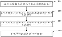
Fig. 11 is a schematic flowchart of a failure recovery method for an SL beam according to an embodiment of the present disclosure, where the method is executed by a second terminal device, and as shown in fig. 11, the failure recovery method for an SL beam may include the following steps:
Among others, in one embodiment of the present disclosure, the specific condition may include at least one of:
the second terminal device is in a connected state;
the second terminal device allocates SL transmission resources based on the dynamic scheduling of the network device.
And, in an embodiment of the present disclosure, after the second terminal device receives the SL-BFR indication, if the second terminal device satisfies a specific condition, the third indication information may be sent to the network device.
In one embodiment of the present disclosure, the third indication information may include at least one of:
a SL-BFR indication;
the SL-BFR indicates the identity of the corresponding first terminal device.
In an embodiment of the present disclosure, the activated beam information may further include an identifier of the first terminal device to which the activated candidate recovery beam is applicable.
And, it should be noted that, when the identification of the first terminal device is not included in the activated beam information, it indicates that the activated candidate recovery beam is applicable to any one or any plurality of second terminal devices connected to the second terminal device SL.
In an embodiment of the present disclosure, in response to that the identification of the first terminal device is included in the activated beam information sent by the network device in step 1102, the second terminal device should send the beam activation indication to the corresponding first terminal device based on the identification.
To sum up, in the SL beam failure recovery method provided in the embodiment of the present disclosure, the first terminal device may determine configuration information, where the configuration information includes at least one of the following: at least one first indication information for indicating an SL beam between a first terminal device and a second terminal device, wherein the second terminal device communicates with the first terminal device through SL; at least one SL wave beam corresponds to the carried SL-BFD-RS; at least one first configuration for SL-BFD; at least one second configuration for SL-BFR. And when the first terminal equipment determines that the SL beam fails based on the configuration information, the first terminal equipment triggers an SL beam failure recovery process. Therefore, in the embodiment of the present disclosure, when the first terminal device communicates with the second terminal device through the SL beam, it is specifically determined whether the SL beam failure occurs based on the configuration information determined by the first terminal device, and when it is determined that the SL beam failure occurs, the SL beam failure recovery process is triggered to perform beam recovery.
Fig. 12 is a schematic flowchart of a failure recovery process of an SL beam according to an embodiment of the present disclosure, where the method is executed by a network device, and as shown in fig. 12, the failure recovery process of the SL beam may include the following steps:
Wherein the configuration information comprises at least one of:
at least one first indication information for indicating a SL beam between a first terminal device and a second terminal device, the second terminal device communicating with the first terminal device through a SL;
at least one SL wave beam corresponds to a carried side link wave beam failure detection reference signal SL-BFD-RS;
at least one first configuration for performing sidelink beam failure detection, SL-BFD;
at least one second configuration to perform SL-BFR for sidelink beam failure recovery.
To sum up, in the SL beam failure recovery method provided in the embodiment of the present disclosure, the first terminal device may determine configuration information, where the configuration information includes at least one of the following: at least one first indication information for indicating an SL beam between a first terminal device and a second terminal device, wherein the second terminal device communicates with the first terminal device through SL; at least one SL wave beam corresponds to the carried SL-BFD-RS; at least one first configuration for SL-BFD; at least one second configuration for SL-BFR. And when the first terminal equipment determines that the SL beam fails based on the configuration information, the first terminal equipment triggers an SL beam failure recovery process. Therefore, in the embodiment of the present disclosure, when the first terminal device communicates with the second terminal device through the SL beam, it is specifically determined whether the SL beam failure occurs based on the configuration information determined by the first terminal device, and when it is determined that the SL beam failure occurs, the SL beam failure recovery process is triggered to perform beam recovery.
Fig. 13 is a schematic flowchart of a failure recovery process of an SL beam according to an embodiment of the present disclosure, where the method is executed by a network device, and as shown in fig. 13, the failure recovery process of the SL beam may include the following steps:
To sum up, in the SL beam failure recovery method provided in the embodiment of the present disclosure, the first terminal device may determine configuration information, where the configuration information includes at least one of the following: at least one first indication information for indicating an SL beam between a first terminal device and a second terminal device, wherein the second terminal device communicates with the first terminal device through SL; at least one SL wave beam corresponds to the carried SL-BFD-RS; at least one first configuration for SL-BFD; at least one second configuration for SL-BFR. And when the first terminal equipment determines that the SL beam fails based on the configuration information, the first terminal equipment triggers an SL beam failure recovery process. Therefore, in the embodiment of the present disclosure, when the first terminal device communicates with the second terminal device through the SL beam, it is specifically determined whether the SL beam failure occurs based on the configuration information determined by the first terminal device, and when it is determined that the SL beam failure occurs, the SL beam failure recovery process is triggered to perform beam recovery.
Fig. 14 is a schematic flowchart of a failure recovery method for an SL beam according to an embodiment of the present disclosure, where the method is executed by a network device, and as shown in fig. 14, the failure recovery method for an SL beam may include the following steps:
The second indication information includes at least one of:
the identifier corresponding to the first terminal device;
an identity of an activated candidate recovery beam autonomously determined by the second terminal device;
a measurement corresponding to the activated candidate recovery beam.
To sum up, in the SL beam failure recovery method provided in the embodiment of the present disclosure, the first terminal device may determine configuration information, where the configuration information includes at least one of the following: at least one first indication information for indicating an SL beam between a first terminal device and a second terminal device, wherein the second terminal device communicates with the first terminal device through SL; at least one SL wave beam corresponds to the carried SL-BFD-RS; at least one first configuration for SL-BFD; at least one second configuration for SL-BFR. And when the first terminal equipment determines that the SL beam fails based on the configuration information, the first terminal equipment triggers an SL beam failure recovery process. Therefore, in the embodiment of the present disclosure, when the first terminal device communicates with the second terminal device through the SL beam, it is specifically determined whether the SL beam failure occurs based on the configuration information determined by the first terminal device, and when it is determined that the SL beam failure occurs, the SL beam failure recovery process is triggered to perform beam recovery.
Fig. 15 is a schematic flowchart of a SL beam failure recovery method according to an embodiment of the present disclosure, where the method is executed by a network device, and as shown in fig. 15, the SL beam failure recovery method may include the following steps:
The third indication information includes at least one of:
the SL-BFR indication;
the SL-BFR indicates the identification of the corresponding first terminal equipment;
wherein the SL-BFR indication includes at least one of:
the BF occurrence frequency meets the SL-BFD-RS identification of the preset condition;
an identification of candidate recovery beams for which measurements exist;
an identification of candidate recovery beams having a measurement result above a second threshold;
identification of the candidate recovery beam with the best measurement result;
a measurement corresponding to a candidate recovery beam and an identification of the candidate recovery beam.
To sum up, in the SL beam failure recovery method provided in the embodiment of the present disclosure, the first terminal device may determine configuration information, where the configuration information includes at least one of the following: at least one piece of first indication information used for indicating SL wave beams between a first terminal device and a second terminal device, wherein the second terminal device is communicated with the first terminal device through SL; at least one SL wave beam corresponds to the carried SL-BFD-RS; at least one first configuration for SL-BFD; at least one second configuration for SL-BFR. And when the first terminal equipment determines that the SL beam fails based on the configuration information, the first terminal equipment triggers an SL beam failure recovery process. Therefore, in the embodiment of the present disclosure, when the first terminal device communicates with the second terminal device through the SL beam, it is specifically determined whether the SL beam failure occurs based on the configuration information determined by the first terminal device, and when it is determined that the SL beam failure occurs, the SL beam failure recovery process is triggered to perform beam recovery.
Fig. 16 is a schematic structural diagram of a communication device according to an embodiment of the present disclosure, and as shown in fig. 16, the device may include:
a processing module configured to determine configuration information, the configuration information including at least one of:
at least one piece of first indication information used for indicating SL wave beams between a first terminal device and a second terminal device, wherein the second terminal device is communicated with the first terminal device through SL;
at least one SL beam correspondingly bears a sidelink beam failure detection reference signal SL-BFD-RS;
at least one first configuration for performing sidelink beam failure detection, SL-BFD;
at least one second configuration for performing a sidelink beam failure recovery, SL-BFR;
the processing module is further configured to trigger an SL beam failure recovery procedure in response to determining that the SL beam fails based on the configuration information.
In summary, in the communication apparatus provided in the embodiment of the present disclosure, the first terminal device may determine the configuration information, where the configuration information includes at least one of the following: at least one first indication information for indicating an SL beam between a first terminal device and a second terminal device, wherein the second terminal device communicates with the first terminal device through SL; at least one SL wave beam corresponds to the carried SL-BFD-RS; at least one first configuration for SL-BFD; at least one second configuration for performing SL-BFR. And when the first terminal equipment determines that the SL beam fails based on the configuration information, the first terminal equipment triggers a SL beam failure recovery process. Therefore, in the embodiment of the present disclosure, when the first terminal device communicates with the second terminal device through the SL beam, it is specifically determined whether the SL beam failure occurs based on the configuration information determined by the first terminal device, and when it is determined that the SL beam failure occurs, the SL beam failure recovery process is triggered to perform beam recovery.
Optionally, in an embodiment of the present disclosure, the processing module is further configured to:
measuring the SL-BFD-RS and determining whether the frequency of the BF occurrence of the beam failure meets a preset condition;
and determining that the SL beam fails in response to determining that the number of BF occurrences satisfies a preset condition.
Optionally, in an embodiment of the present disclosure, the first indication information is a transmission configuration indication TCI corresponding to the SL beam.
Optionally, in an embodiment of the present disclosure, the first configuration includes at least one of:
presetting time length;
a first threshold value;
wherein the first threshold value is used for: and when the measured BF occurrence frequency reaches the first threshold value, or when the measured BF occurrence frequency reaches the first threshold value in the preset time length, determining that the SL wave beam failure occurs.
Optionally, in an embodiment of the present disclosure, the second configuration includes at least one of:
an identification of at least one candidate recovery beam;
at least one candidate recovery beam corresponds to the carried reference signal;
a second threshold value for beam recovery.
Optionally, in an embodiment of the present disclosure, different SL-BFD-RSs correspond to different first configurations; and/or the presence of a gas in the atmosphere,
the different SL-BFD-RSs correspond to a different second configuration.
Optionally, in an embodiment of the present disclosure, the processing module is further configured to:
receiving the configuration information sent by the network equipment;
and receiving the configuration information sent by the second terminal equipment.
Optionally, in an embodiment of the present disclosure, the processing module is further configured to:
detecting whether BF occurs or not in the process of measuring the SL-BFD-RS;
counting the BF occurrence frequency;
and determining that the preset condition is met in response to the BF occurrence frequency reaching the first threshold value.
Optionally, in an embodiment of the present disclosure, the processing module is further configured to:
in the process of measuring the SL-BFD-RS, responding to the initial generation of BF, starting a timer, wherein the timing duration of the timer is the preset duration;
counting the BF occurrence frequency;
and responding to the starting period of the timer, determining that the BF occurrence times reach the first threshold value, and determining that the preset condition is met.
Optionally, in an embodiment of the present disclosure, the apparatus is further configured to:
and setting the count value of the BF occurrence number to zero in response to the time-out of the timer.
Optionally, in an embodiment of the present disclosure, the apparatus is further configured to:
and obtaining a measurement result, wherein the measurement result is obtained by measuring the reference signal carried by the candidate recovery beam correspondingly.
Optionally, in an embodiment of the present disclosure, the processing module is further configured to:
sending a SL-BFR indication to a second terminal device;
the SL-BFR indication includes at least one of:
the BF occurrence frequency meets the SL-BFD-RS identification of the preset condition;
an identification of candidate recovery beams for which measurements exist;
an identification of candidate recovery beams having a measurement result higher than a second threshold value;
identification of the candidate recovery beam with the best measurement result;
a measurement corresponding to a candidate recovery beam and an identification of the candidate recovery beam.
Optionally, in an embodiment of the present disclosure, the processing module is further configured to:
receiving a beam activation indication sent by the second terminal device, wherein the beam activation indication comprises an identifier of an activated candidate recovery beam;
determining an activated candidate recovery beam based on the beam activation indication;
communicating with a second terminal device based on the activated candidate recovery beam.
Optionally, in an embodiment of the present disclosure, the measurement result includes at least one of:
reference signal received power, RSRP;
reference signal received quality SINR.
Fig. 17 is a schematic structural diagram of a communication device according to an embodiment of the present disclosure, and as shown in fig. 17, the device may include:
a processing module for determining configuration information; the configuration information includes at least one of:
at least one piece of first indication information for indicating a SL beam between a first terminal device and a second terminal device, wherein the second terminal device communicates with the first terminal device through SL;
at least one SL wave beam corresponds to the carried SL-BFD-RS;
at least one first configuration for SL-BFD;
at least one second configuration for SL-BFR.
In summary, in the communication apparatus provided in the embodiment of the present disclosure, the first terminal device may determine configuration information, where the configuration information includes at least one of the following: at least one first indication information for indicating an SL beam between a first terminal device and a second terminal device, wherein the second terminal device communicates with the first terminal device through SL; at least one SL wave beam corresponds to the carried SL-BFD-RS; at least one first configuration for SL-BFD; at least one second configuration for SL-BFR. And when the first terminal equipment determines that the SL beam fails based on the configuration information, the first terminal equipment triggers a SL beam failure recovery process. Therefore, in the embodiment of the present disclosure, when the first terminal device communicates with the second terminal device through the SL beam, it is specifically determined whether the SL beam failure occurs based on the configuration information determined by the first terminal device, and when it is determined that the SL beam failure occurs, the SL beam failure recovery process is triggered to perform beam recovery.
Optionally, in an embodiment of the present disclosure, the apparatus is further configured to:
receiving configuration information sent by network equipment; or
And receiving configuration information sent by the network equipment and an identifier of the first terminal equipment applicable to the configuration information.
Optionally, in an embodiment of the present disclosure, the first indication information is a transmission configuration indication TCI corresponding to the SL beam.
Optionally, in an embodiment of the present disclosure, the first configuration includes at least one of:
presetting time length;
a first threshold value;
wherein the first threshold is used for: and when the measured BF occurrence frequency reaches the first threshold value, or when the measured BF occurrence frequency reaches the first threshold value in the preset time length, determining that the SL wave beam failure occurs.
Optionally, in an embodiment of the present disclosure, the second configuration includes at least one of:
an identification of at least one candidate recovery beam;
at least one candidate recovery beam corresponds to the carried reference signal;
a second threshold value for beam recovery.
Optionally, in an embodiment of the present disclosure, different SL-BFD-RSs correspond to different first configurations; and/or the presence of a gas in the gas,
the different SL-BFD-RSs correspond to a different second configuration.
Optionally, in an embodiment of the present disclosure, the apparatus is further configured to:
and sending the configuration information to the first terminal equipment.
Optionally, in an embodiment of the present disclosure, the transceiver module is further configured to:
and responding to the identifier of the first terminal equipment which is suitable for the configuration information and sent to the second terminal equipment by the network equipment, and sending the configuration information to the first terminal equipment corresponding to the identifier.
Optionally, in an embodiment of the present disclosure, the method further includes:
receiving a SL-BFR instruction sent by first terminal equipment;
the SL-BFR indication includes at least one of:
the BF occurrence frequency meets the SL-BFD-RS identification of the preset condition;
an identification of candidate recovery beams for which measurements exist;
an identification of candidate recovery beams having a measurement result above a second threshold;
identification of the candidate recovery beam with the best measurement result;
a measurement corresponding to a candidate recovery beam and an identification of the candidate recovery beam.
Optionally, in an embodiment of the present disclosure, the apparatus is further configured to:
the second terminal device autonomously determines a candidate recovery beam to activate.
Optionally, in an embodiment of the present disclosure, in response to that the second terminal device is in a connected state, and/or that the second terminal device allocates SL transmission resources based on dynamic scheduling of a network device, the apparatus is further configured to:
sending second indication information to the network equipment; the second indication information includes at least one of:
the identifier corresponding to the first terminal device;
an identity of an activated candidate recovery beam autonomously determined by the second terminal device;
a measurement corresponding to the activated candidate recovery beam.
Optionally, in an embodiment of the present disclosure, in response to that the second terminal device is in a connected state, and/or that the second terminal device allocates SL transmission resources based on dynamic scheduling of a network device, after receiving the SL-BFR indication sent by the first terminal device, the apparatus is further configured to:
sending third indication information to the network device, where the third indication information includes at least one of:
the SL-BFR indication;
and the SL-BFR indicates the identification of the corresponding first terminal equipment.
Optionally, in an embodiment of the present disclosure, the apparatus is further configured to:
and acquiring activated beam information sent by the network equipment, wherein the activated beam information comprises the identification of the activated candidate recovery beam.
Optionally, in an embodiment of the present disclosure, the apparatus is further configured to:
sending a beam activation indication to the first terminal device, wherein the beam activation indication comprises an identifier of an activated candidate recovery beam;
communicating with a first terminal device based on the activated candidate recovery beam.
Fig. 18 is a schematic structural diagram of a communication device according to an embodiment of the present disclosure, and as shown in fig. 18, the device may include:
a transceiver module, configured to send configuration information to a first terminal device, where the configuration information includes at least one of:
at least one first indication information for indicating a SL beam between a first terminal device and a second terminal device, the second terminal device communicating with the first terminal device through a SL;
at least one SL beam correspondingly bears a sidelink beam failure detection reference signal SL-BFD-RS;
at least one first configuration for performing sidelink beam failure detection, SL-BFD;
at least one second configuration to perform SL-BFR for sidelink beam failure recovery.
In summary, in the communication apparatus provided in the embodiment of the present disclosure, the first terminal device may determine configuration information, where the configuration information includes at least one of the following: at least one piece of first indication information used for indicating SL wave beams between a first terminal device and a second terminal device, wherein the second terminal device is communicated with the first terminal device through SL; at least one SL wave beam corresponds to the carried SL-BFD-RS; at least one first configuration for SL-BFD; at least one second configuration for performing SL-BFR. And when the first terminal equipment determines that the SL beam fails based on the configuration information, the first terminal equipment triggers an SL beam failure recovery process. Therefore, in the embodiment of the present disclosure, when the first terminal device communicates with the second terminal device through the SL beam, it is specifically determined whether the SL beam failure occurs based on the determined configuration information, and when it is determined that the SL beam failure occurs, the SL beam failure recovery procedure is triggered to perform beam recovery.
Optionally, in an embodiment of the present disclosure, the first indication information is a transmission configuration indication TCI corresponding to the SL beam.
Optionally, in an embodiment of the present disclosure, the first configuration includes at least one of:
presetting time length;
a first threshold value;
wherein the first threshold value is used for: and when the BF occurrence frequency reaches the first threshold value, or when the BF occurrence frequency reaches the first threshold value in the preset time length, determining that the SL wave beam fails to occur.
Optionally, in an embodiment of the present disclosure, the second configuration includes at least one of:
an identification of at least one candidate recovery beam;
at least one candidate recovery beam corresponds to the carried reference signal;
a second threshold value for beam recovery.
Optionally, in an embodiment of the present disclosure, different SL-BFD-RSs correspond to different first configurations; and/or the presence of a gas in the atmosphere,
the different SL-BFD-RS corresponds to a different second configuration.
Optionally, in an embodiment of the present disclosure, the apparatus is further configured to:
and sending configuration information and/or an identifier of the first terminal equipment applicable to the configuration information to the second terminal equipment.
Optionally, in an embodiment of the present disclosure, the apparatus is further configured to:
receiving second indication information sent by the second terminal equipment; the second indication information includes at least one of:
the identifier corresponding to the first terminal device;
an identity of an activated candidate recovery beam autonomously determined by the second terminal device;
a measurement corresponding to the activated candidate recovery beam.
Optionally, in an embodiment of the present disclosure, the apparatus is further configured to:
receiving third indication information sent by the second terminal device, where the third indication information includes at least one of the following:
the SL-BFR indication;
the SL-BFR indicates the identification of the corresponding first terminal equipment;
wherein the SL-BFR indication includes at least one of:
the BF occurrence frequency meets the SL-BFD-RS identification of the preset condition;
an identification of candidate recovery beams for which measurements exist;
an identification of candidate recovery beams having a measurement result above a second threshold;
identification of the candidate recovery beam with the best measurement result;
a measurement corresponding to a candidate recovery beam and an identification of the candidate recovery beam.
Optionally, in an embodiment of the present disclosure, the apparatus is further configured to:
determining an activated candidate recovery beam;
and sending activated beam information to the second terminal equipment, wherein the activated beam information comprises the identification of the activated candidate recovery beam.
Referring to fig. 19, fig. 19 is a schematic structural diagram of a communication device 1900 according to an embodiment of the present disclosure. The communication apparatus 1900 may be a network device, a terminal device, a chip system, or a processor supporting the network device to implement the method, or a chip, a chip system, or a processor supporting the terminal device to implement the method. The apparatus may be configured to implement the method described in the method embodiment, and refer to the description in the method embodiment.
The communications device 1900 may include one or more processors 1901. The processor 1901 may be a general-purpose processor, a special-purpose processor, or the like. For example, a baseband processor or a central processor. The baseband processor may be configured to process communication protocols and communication data, and the central processor may be configured to control a communication device (e.g., a base station, a baseband chip, a terminal device chip, a DU or CU, etc.), execute a computer program, and process data of the computer program.
Optionally, the communication device 1900 may further include one or more memories 1902, on which a computer program 1904 may be stored, and the processor 1901 executes the computer program 1904, so that the communication device 1900 executes the method described in the above method embodiments. Optionally, the memory 1902 may further store data therein. The communications device 1900 and the memory 1902 may be separate or integrated together.
Optionally, the communications device 1900 may further include a transceiver 1905 and an antenna 1906. The transceiver 1905 may be referred to as a transceiving unit, a transceiver, or a transceiving circuit, etc. for implementing transceiving functions. The transceiver 1905 may include a receiver and a transmitter, and the receiver may be referred to as a receiver or a receiving circuit, etc. for implementing a receiving function; the transmitter may be referred to as a transmitter or a transmission circuit, etc. for implementing the transmission function.
Optionally, one or more interface circuits 1907 may also be included in communications device 1900. The interface circuit 1907 is used for receiving code instructions and transmitting them to the processor 1901. The processor 1901 executes the code instructions to cause the communication device 1900 to perform the methods described in the above method embodiments.
In one implementation, a transceiver may be included in the processor 1901 for performing receive and transmit functions. The transceiver may be, for example, a transceiver circuit, or an interface circuit. The transmit and receive circuitry, interfaces or interface circuitry used to implement the receive and transmit functions may be separate or integrated. The transceiver circuit, the interface circuit or the interface circuit may be used for reading and writing code/data, or the transceiver circuit, the interface circuit or the interface circuit may be used for transmitting or transferring signals.
In one implementation, the processor 1901 may store a computer program 1903, and the computer program 1903, when executed on the processor 1901, may cause the communication apparatus 1900 to perform the method described in the above method embodiment. The computer program 1903 may be solidified in the processor 1901, in which case the processor 1901 may be implemented by hardware.
In one implementation, communications device 1900 may include circuitry that may implement the functionality of transmitting or receiving or communicating in the foregoing method embodiments. The processors and transceivers described herein may be implemented on Integrated Circuits (ICs), analog ICs, radio Frequency Integrated Circuits (RFICs), mixed signal ICs, application Specific Integrated Circuits (ASICs), printed Circuit Boards (PCBs), electronic devices, and the like. The processor and transceiver may also be fabricated using various IC process technologies, such as Complementary Metal Oxide Semiconductor (CMOS), N-type metal oxide semiconductor (NMOS), P-type metal oxide semiconductor (PMOS), bipolar Junction Transistor (BJT), bipolar CMOS (BiCMOS), silicon germanium (SiGe), gallium arsenide (GaAs), and the like.
The communication apparatus in the description of the above embodiment may be a network device or a terminal device, but the scope of the communication apparatus described in the present application is not limited thereto, and the structure of the communication apparatus may not be limited by fig. 19. The communication means may be a stand-alone device or may be part of a larger device. For example, the communication means may be:
(1) A stand-alone integrated circuit IC, or chip, or system-on-chip or subsystem;
(2) A set of one or more ICs, which optionally may also include storage means for storing data, computer programs;
(3) An ASIC, such as a Modem (Modem);
(4) A module that may be embedded within other devices;
(5) Receivers, terminal devices, intelligent terminal devices, cellular phones, wireless devices, handsets, mobile units, in-vehicle devices, network devices, cloud devices, artificial intelligence devices, and the like;
(6) Others, and so forth.
For the case that the communication device may be a chip or a chip system, see the schematic structural diagram of the chip shown in fig. 20. The chip shown in fig. 20 includes a processor 2001 and an interface 2002. The number of the processors 2001 may be one or more, and the number of the interfaces 2002 may be plural.
Optionally, the chip further comprises a memory 2003, the memory 2003 being used for storing necessary computer programs and data.
Those skilled in the art will also appreciate that the various illustrative logical blocks and steps (step) set forth in the embodiments of the present application may be implemented in electronic hardware, computer software, or combinations of both. Whether such functionality is implemented as hardware or software depends upon the particular application and design requirements of the overall system. Those skilled in the art may implement the described functionality in varying ways for each particular application, but such implementation decisions should not be interpreted as causing a departure from the scope of the embodiments of the present application.
The present application further provides a readable storage medium having stored thereon instructions which, when executed by a computer, implement the functionality of any of the above-described method embodiments.
The present application also provides a computer program product which, when executed by a computer, implements the functionality of any of the above-described method embodiments.
In the above embodiments, all or part of the implementation may be realized by software, hardware, firmware, or any combination thereof. When implemented in software, may be implemented in whole or in part in the form of a computer program product. The computer program product includes one or more computer programs. The procedures or functions described in accordance with the embodiments of the present application are generated in whole or in part when the computer program is loaded and executed on a computer. The computer may be a general purpose computer, a special purpose computer, a network of computers, or other programmable device. The computer program can be stored in a computer readable storage medium or transmitted from one computer readable storage medium to another computer readable storage medium, for example, the computer program can be transmitted from one website, computer, server, or data center to another website, computer, server, or data center by wire (e.g., coaxial cable, fiber optic, digital Subscriber Line (DSL)) or wireless (e.g., infrared, wireless, microwave, etc.). The computer-readable storage medium can be any available medium that can be accessed by a computer or a data storage device, such as a server, a data center, etc., that incorporates one or more of the available media. The usable medium may be a magnetic medium (e.g., a floppy disk, a hard disk, a magnetic tape), an optical medium (e.g., a Digital Video Disk (DVD)), or a semiconductor medium (e.g., a Solid State Disk (SSD)), among others.
Those of ordinary skill in the art will understand that: various numbers of the first, second, etc. mentioned in this application are only for convenience of description and distinction, and are not used to limit the scope of the embodiments of this application, and also represent a sequence order.
At least one of the present applications may also be described as one or more, and a plurality may be two, three, four or more, and the present application is not limited thereto. In the embodiment of the present application, for a technical feature, the technical features in the technical feature are distinguished by "first", "second", "third", "a", "B", "C", and "D", and the like, and the technical features described in "first", "second", "third", "a", "B", "C", and "D" are not in a sequential order or a size order.
The correspondence shown in the tables in the present application may be configured or predefined. The values of the information in each table are merely examples, and may be configured as other values, which is not limited in the present application. When the correspondence between the information and each parameter is configured, it is not necessarily required that all the correspondence indicated in each table be configured. For example, in the table in the present application, the correspondence shown in some rows may not be configured. For another example, appropriate modification adjustments, such as splitting, merging, etc., can be made based on the above tables. The names of the parameters in the tables may be other names understandable by the communication device, and the values or the expression of the parameters may be other values or expressions understandable by the communication device. When the above tables are implemented, other data structures may be used, for example, arrays, queues, containers, stacks, linear tables, pointers, linked lists, trees, graphs, structures, classes, heaps, hash tables, or the like may be used.
Predefinition in this application may be understood as defining, predefining, storing, pre-negotiating, pre-configuring, curing, or pre-firing.
Those of ordinary skill in the art will appreciate that the various illustrative elements and algorithm steps described in connection with the embodiments disclosed herein may be implemented as electronic hardware or combinations of computer software and electronic hardware. Whether such functionality is implemented as hardware or software depends upon the particular application and design constraints imposed on the implementation. Skilled artisans may implement the described functionality in varying ways for each particular application, but such implementation decisions should not be interpreted as causing a departure from the scope of the present application.
It is clear to those skilled in the art that, for convenience and brevity of description, the specific working processes of the above-described systems, apparatuses and units may refer to the corresponding processes in the foregoing method embodiments, and are not described herein again.
The above description is only for the specific embodiments of the present application, but the scope of the present application is not limited thereto, and any person skilled in the art can easily think of the changes or substitutions within the technical scope of the present application, and shall be covered by the scope of the present application. Therefore, the protection scope of the present application shall be subject to the protection scope of the claims.
Claims (34)
1. A method of sidelink SL beam failure recovery, the method being performed by a first terminal device, the method comprising:
determining configuration information, the configuration information including at least one of:
at least one first indication information for indicating a SL beam between a first terminal device and a second terminal device, the second terminal device communicating with the first terminal device through a SL;
at least one SL beam correspondingly bears a sidelink beam failure detection reference signal SL-BFD-RS;
at least one first configuration for performing sidelink beam failure detection, SL-BFD;
at least one second configuration for performing SL-BFR for sidelink beam failure recovery;
triggering an SL beam failure recovery procedure in response to determining that the SL beam fails based on the configuration information.
2. The method of claim 1, wherein the determining a SL beam failure based on the configuration information comprises:
measuring the SL-BFD-RS and determining whether the frequency of the BF occurrence of the wave beam failure meets a preset condition;
and determining that the SL beam fails in response to determining that the number of BF occurrences satisfies a preset condition.
3. The method of claim 1, wherein the first indication information indicates a Transmission Configuration Indication (TCI) for the SL beam.
4. The method of claim 1, wherein the first configuration comprises at least one of:
presetting time length;
a first threshold value;
wherein the first threshold is used for: and when the BF occurrence frequency reaches the first threshold value, or when the BF occurrence frequency reaches the first threshold value in the preset time length, determining that the SL wave beam fails to occur.
5. The method of claim 1, wherein the second configuration comprises at least one of:
an identification of at least one candidate recovery beam;
at least one candidate recovery beam corresponds to the carried reference signal;
a second threshold value for beam recovery.
6. The method of claim 1, wherein different SL-BFD-RSs correspond to different first configurations; and/or the presence of a gas in the gas,
the different SL-BFD-RS corresponds to a different second configuration.
7. The method of claim 1, wherein the determining configuration information comprises at least one of:
receiving the configuration information sent by the network equipment;
and receiving the configuration information sent by the second terminal equipment.
8. The method of claim 4, wherein said measuring the SL-BFD-RS and determining whether the number of BF occurrences satisfies a predetermined condition comprises:
detecting whether BF occurs or not in the process of measuring the SL-BFD-RS;
counting the BF occurrence frequency;
and determining that the preset condition is met in response to the BF occurrence frequency reaching the first threshold value.
9. The method of claim 4, wherein said measuring the SL-BFD-RS and determining whether the number of BF occurrences satisfies a predetermined condition comprises:
in the process of measuring the SL-BFD-RS, responding to the initial BF occurrence, starting a timer, wherein the timing duration of the timer is the preset duration;
counting the BF occurrence frequency;
and responding to the starting period of the timer, determining that the BF occurrence times reach the first threshold value, and determining that the preset condition is met.
10. The method of claim 9, wherein the method further comprises:
and in response to the timer being out of time, setting a count value of the number of BF occurrences to zero.
11. The method of claim 5, wherein the method further comprises:
and obtaining a measurement result, wherein the measurement result is obtained by measuring the reference signal carried by the candidate recovery beam correspondingly.
12. The method of claim 11, wherein the triggering the SL beam failure recovery procedure comprises:
sending a SL-BFR indication to a second terminal device;
the SL-BFR indication includes at least one of:
the BF occurrence frequency meets the SL-BFD-RS identification of the preset condition;
an identification of candidate recovery beams for which measurements exist;
an identification of candidate recovery beams having a measurement result higher than a second threshold value;
identification of the candidate recovery beam with the best measurement result;
a measurement corresponding to a candidate recovery beam and an identification of the candidate recovery beam.
13. The method of claim 1 or 12, wherein the triggering the SL beam failure recovery procedure comprises:
receiving a beam activation indication sent by the second terminal device, wherein the beam activation indication comprises an identifier of an activated candidate recovery beam;
determining an activated candidate recovery beam based on the beam activation indication;
communicating with a second terminal device based on the activated candidate recovery beam.
14. The method of claim 12, wherein the measurement results include at least one of:
reference signal received power, RSRP;
reference signal received quality SINR.
15. A SL beam failure recovery method, performed by a second terminal device, the method comprising:
determining configuration information; the configuration information includes at least one of:
at least one piece of first indication information for indicating a SL beam between a first terminal device and a second terminal device, wherein the second terminal device communicates with the first terminal device through SL;
at least one SL wave beam corresponds to the carried SL-BFD-RS;
at least one first configuration for SL-BFD;
at least one second configuration for SL-BFR.
16. The method of claim 15, wherein the determining configuration information comprises:
receiving configuration information sent by network equipment; or
And receiving configuration information sent by the network equipment and an identifier of the first terminal equipment applicable to the configuration information.
17. The method of claim 16, wherein the method further comprises:
and sending the configuration information to the first terminal equipment.
18. The method of claim 17, wherein said sending said configuration information to said first terminal device comprises:
and responding to the identifier of the first terminal equipment which is suitable for the configuration information and sent to the second terminal equipment by the network equipment, and sending the configuration information to the first terminal equipment corresponding to the identifier.
19. The method of claim 15, wherein the method further comprises:
receiving a SL-BFR instruction sent by first terminal equipment;
the SL-BFR indication includes at least one of:
the BF occurrence frequency meets the SL-BFD-RS identification of the preset condition;
an identification of candidate recovery beams for which measurements exist;
an identification of candidate recovery beams having a measurement result above a second threshold;
identification of the candidate recovery beam with the best measurement result;
a measurement corresponding to a candidate recovery beam and an identification of the candidate recovery beam.
20. The method of claim 19, wherein the method further comprises:
the second terminal device autonomously determines a candidate recovery beam to activate.
21. The method of claim 20, wherein in response to the second terminal device being in a connected state and/or the second terminal device allocating SL transmission resources based on dynamic scheduling by a network device, the method further comprises:
sending second indication information to the network equipment; the second indication information includes at least one of:
the identifier corresponding to the first terminal device;
an identity of an activated candidate recovery beam autonomously determined by the second terminal device;
a measurement corresponding to the activated candidate recovery beam.
22. The method of claim 19, wherein in response to the second terminal device being in a connected state and/or the second terminal device allocating SL transmission resources based on dynamic scheduling by a network device, the method further comprises:
sending third indication information to the network device, where the third indication information includes at least one of:
the SL-BFR indication;
and the SL-BFR indicates the identification of the corresponding first terminal equipment.
23. The method of claim 22, wherein the method further comprises:
and acquiring activated beam information sent by the network equipment, wherein the activated beam information comprises the identification of the activated candidate recovery beam.
24. The method of claim 20 or 23, wherein the method further comprises:
sending a beam activation indication to the first terminal device, wherein the beam activation indication comprises an identification of an activated candidate recovery beam;
communicating with a first terminal device based on the activated candidate recovery beam.
25. A method for SL beam failure recovery, the method being performed by a network device, the method comprising:
sending configuration information to a first terminal device, wherein the configuration information comprises at least one of the following:
at least one piece of first indication information used for indicating SL wave beams between a first terminal device and a second terminal device, wherein the second terminal device is communicated with the first terminal device through SL;
at least one SL beam correspondingly bears a sidelink beam failure detection reference signal SL-BFD-RS;
at least one first configuration for performing sidelink beam failure detection, SL-BFD;
at least one second configuration to perform SL-BFR for sidelink beam failure recovery.
26. The method of claim 25, wherein the method further comprises:
and sending configuration information and/or an identifier of the first terminal equipment applicable to the configuration information to the second terminal equipment.
27. The method of claim 25 or 26, wherein the method further comprises:
receiving second indication information sent by the second terminal equipment; the second indication information includes at least one of:
the identifier corresponding to the first terminal device;
an identity of an activated candidate recovery beam autonomously determined by the second terminal device;
a measurement corresponding to the activated candidate recovery beam.
28. The method of claim 25 or 26, wherein the method further comprises:
receiving third indication information sent by the second terminal device, where the third indication information includes at least one of the following:
the SL-BFR indication;
the SL-BFR indicates the identification of the corresponding first terminal equipment;
wherein the SL-BFR indication comprises at least one of:
the BF occurrence frequency meets the SL-BFD-RS identification of the preset condition;
an identification of candidate recovery beams for which measurements exist;
an identification of candidate recovery beams having a measurement result higher than a second threshold value;
identification of the candidate recovery beam with the best measurement result;
a measurement corresponding to a candidate recovery beam and an identification of the candidate recovery beam.
29. The method of claim 28, wherein the method further comprises:
determining an activated candidate recovery beam;
and sending activated beam information to the second terminal equipment, wherein the activated beam information comprises the identification of the activated candidate recovery beam.
30. A communication apparatus, the apparatus being configured in a first terminal device, comprising:
a processing module configured to determine configuration information, the configuration information including at least one of:
at least one piece of first indication information used for indicating SL wave beams between a first terminal device and a second terminal device, wherein the second terminal device is communicated with the first terminal device through SL;
at least one SL beam correspondingly bears a sidelink beam failure detection reference signal SL-BFD-RS;
at least one first configuration for performing sidelink beam failure detection, SL-BFD;
at least one second configuration for performing SL-BFR for sidelink beam failure recovery;
the processing module is further configured to trigger an SL beam failure recovery procedure in response to determining that the SL beam failed based on the configuration information.
31. A communication apparatus, wherein the apparatus is configured in a second terminal device, comprising:
a processing module for determining configuration information; the configuration information includes at least one of:
at least one first indication information for indicating an SL beam between the first terminal device and the second terminal device;
at least one SL wave beam corresponds to the carried SL-BFD-RS;
at least one first configuration for SL-BFD;
at least one second configuration for SL-BFR.
32. A communications apparatus, configured in a network device, comprising:
a transceiver module, configured to send configuration information to a first terminal device, where the configuration information includes at least one of:
at least one piece of first indication information used for indicating SL wave beams between a first terminal device and a second terminal device, wherein the second terminal device is communicated with the first terminal device through SL;
at least one SL beam correspondingly bears a sidelink beam failure detection reference signal SL-BFD-RS;
at least one first configuration for performing sidelink beam failure detection, SL-BFD;
at least one second configuration to perform SL-BFR for sidelink beam failure recovery.
33. A communications apparatus, comprising a processor and a memory, wherein the memory has stored therein a computer program, the processor executes the computer program stored in the memory to cause the apparatus to perform the method of any one of claims 1 to 14, or the processor executes the computer program stored in the memory to cause the apparatus to perform the method of claims 15 to 24, or the processor executes the computer program stored in the memory to cause the apparatus to perform the method of claims 25 to 29.
34. A computer readable storage medium storing instructions that, when executed, cause the method of any of claims 1 to 14 to be implemented, or that, when executed, cause the method of claims 15 to 24 to be implemented, or that, when executed, cause the method of claims 25 to 29 to be implemented.
Applications Claiming Priority (1)
| Application Number | Priority Date | Filing Date | Title |
|---|---|---|---|
| PCT/CN2022/110388 WO2024026800A1 (en) | 2022-08-04 | 2022-08-04 | Sidelink sl beam failure recovery method/apparatus/device, and storage medium |
Publications (1)
| Publication Number | Publication Date |
|---|---|
| CN115516902A true CN115516902A (en) | 2022-12-23 |
Family
ID=84513747
Family Applications (1)
| Application Number | Title | Priority Date | Filing Date |
|---|---|---|---|
| CN202280002563.7A Pending CN115516902A (en) | 2022-08-04 | 2022-08-04 | Method, device and equipment for recovering failure of side-link SL beam and storage medium |
Country Status (2)
| Country | Link |
|---|---|
| CN (1) | CN115516902A (en) |
| WO (1) | WO2024026800A1 (en) |
Family Cites Families (5)
| Publication number | Priority date | Publication date | Assignee | Title |
|---|---|---|---|---|
| US11425775B2 (en) * | 2019-02-01 | 2022-08-23 | Lenovo (Singapore) Pte. Ltd. | Sidelink failure detection and recovery |
| EP4027680A4 (en) * | 2019-09-04 | 2022-10-26 | Sony Group Corporation | Communication control device, communication control method, and communication control program |
| CA3094871A1 (en) * | 2019-09-30 | 2021-03-30 | Comcast Cable Communications, Llc | Beam management and failure recovery for communications |
| US11924902B2 (en) * | 2020-07-02 | 2024-03-05 | Qualcomm Incorporated | Directional sidelink (SL) beam failure detection |
| US20220022068A1 (en) * | 2020-07-17 | 2022-01-20 | Qualcomm Incorporated | Techniques for bi-directional sidelink beam failure detection |
-
2022
- 2022-08-04 CN CN202280002563.7A patent/CN115516902A/en active Pending
- 2022-08-04 WO PCT/CN2022/110388 patent/WO2024026800A1/en unknown
Also Published As
| Publication number | Publication date |
|---|---|
| WO2024026800A1 (en) | 2024-02-08 |
Similar Documents
| Publication | Publication Date | Title |
|---|---|---|
| CN113892276A (en) | Information transmission method and device | |
| WO2023133736A1 (en) | Method and apparatus for determining listen-before-talk failure | |
| CN114175840B (en) | Random access method and device | |
| CN115136660A (en) | Relay connection method and device | |
| CN115136653A (en) | Cell switching method and device | |
| CN114731486A (en) | Method and device for reporting position information | |
| CN115516902A (en) | Method, device and equipment for recovering failure of side-link SL beam and storage medium | |
| WO2024026801A1 (en) | Sidelink (sl) beam configuration method and apparatus, device and storage medium | |
| WO2023240418A1 (en) | Method for detecting scheduling information for multi-cell scheduling, and apparatuses therefor | |
| WO2024045044A1 (en) | Timing advance (ta) measurement method and apparatus | |
| WO2024031485A1 (en) | Transmission method and apparatus therefor | |
| WO2024016245A1 (en) | Information indication method and apparatus, and device and storage medium | |
| WO2024060143A1 (en) | Reporting method/apparatus/device, and storage medium | |
| WO2023168576A1 (en) | Method for determining sounding reference signal (srs) resource configuration information, and apparatus using same | |
| CN114026907B (en) | Method and device for measuring uplink wave beam | |
| WO2024016360A1 (en) | Random access method, apparatus, device, and storage medium | |
| EP4362564A1 (en) | Timing relationship adjustment method and apparatus | |
| WO2023168575A1 (en) | Antenna switching capability reporting method and apparatus using same | |
| WO2024060154A1 (en) | Reporting method, apparatus and device, and storage medium | |
| WO2023283964A1 (en) | Method and apparatus for configuring mobility measurement of multi-carrier cell | |
| CN114902721A (en) | Processing method and device for measurement configuration | |
| CN115280848A (en) | System information configuration method/device/equipment and storage medium | |
| CN114846828A (en) | Method and device for acquiring Channel State Information (CSI) report and storage medium | |
| CN115918165A (en) | Target UE determination method and device used in terminal equipment UE-UE relay scene | |
| CN117643147A (en) | Mobility management method and device thereof |
Legal Events
| Date | Code | Title | Description |
|---|---|---|---|
| PB01 | Publication | ||
| PB01 | Publication | ||
| SE01 | Entry into force of request for substantive examination | ||
| SE01 | Entry into force of request for substantive examination |