CN115480667A - Capacitive communication channel for auxiliary devices - Google Patents
Capacitive communication channel for auxiliary devices Download PDFInfo
- Publication number
- CN115480667A CN115480667A CN202210679576.XA CN202210679576A CN115480667A CN 115480667 A CN115480667 A CN 115480667A CN 202210679576 A CN202210679576 A CN 202210679576A CN 115480667 A CN115480667 A CN 115480667A
- Authority
- CN
- China
- Prior art keywords
- capacitive
- auxiliary device
- electrodes
- input device
- input
- Prior art date
- Legal status (The legal status is an assumption and is not a legal conclusion. Google has not performed a legal analysis and makes no representation as to the accuracy of the status listed.)
- Pending
Links
Images


Classifications
-
- G—PHYSICS
- G06—COMPUTING; CALCULATING OR COUNTING
- G06F—ELECTRIC DIGITAL DATA PROCESSING
- G06F3/00—Input arrangements for transferring data to be processed into a form capable of being handled by the computer; Output arrangements for transferring data from processing unit to output unit, e.g. interface arrangements
- G06F3/01—Input arrangements or combined input and output arrangements for interaction between user and computer
- G06F3/03—Arrangements for converting the position or the displacement of a member into a coded form
- G06F3/041—Digitisers, e.g. for touch screens or touch pads, characterised by the transducing means
- G06F3/0416—Control or interface arrangements specially adapted for digitisers
- G06F3/04166—Details of scanning methods, e.g. sampling time, grouping of sub areas or time sharing with display driving
-
- G—PHYSICS
- G06—COMPUTING; CALCULATING OR COUNTING
- G06F—ELECTRIC DIGITAL DATA PROCESSING
- G06F3/00—Input arrangements for transferring data to be processed into a form capable of being handled by the computer; Output arrangements for transferring data from processing unit to output unit, e.g. interface arrangements
- G06F3/01—Input arrangements or combined input and output arrangements for interaction between user and computer
- G06F3/03—Arrangements for converting the position or the displacement of a member into a coded form
- G06F3/041—Digitisers, e.g. for touch screens or touch pads, characterised by the transducing means
- G06F3/044—Digitisers, e.g. for touch screens or touch pads, characterised by the transducing means by capacitive means
-
- G—PHYSICS
- G06—COMPUTING; CALCULATING OR COUNTING
- G06F—ELECTRIC DIGITAL DATA PROCESSING
- G06F3/00—Input arrangements for transferring data to be processed into a form capable of being handled by the computer; Output arrangements for transferring data from processing unit to output unit, e.g. interface arrangements
- G06F3/01—Input arrangements or combined input and output arrangements for interaction between user and computer
- G06F3/03—Arrangements for converting the position or the displacement of a member into a coded form
- G06F3/041—Digitisers, e.g. for touch screens or touch pads, characterised by the transducing means
- G06F3/0416—Control or interface arrangements specially adapted for digitisers
- G06F3/04164—Connections between sensors and controllers, e.g. routing lines between electrodes and connection pads
-
- G—PHYSICS
- G06—COMPUTING; CALCULATING OR COUNTING
- G06F—ELECTRIC DIGITAL DATA PROCESSING
- G06F3/00—Input arrangements for transferring data to be processed into a form capable of being handled by the computer; Output arrangements for transferring data from processing unit to output unit, e.g. interface arrangements
- G06F3/01—Input arrangements or combined input and output arrangements for interaction between user and computer
- G06F3/03—Arrangements for converting the position or the displacement of a member into a coded form
- G06F3/041—Digitisers, e.g. for touch screens or touch pads, characterised by the transducing means
- G06F3/044—Digitisers, e.g. for touch screens or touch pads, characterised by the transducing means by capacitive means
- G06F3/0446—Digitisers, e.g. for touch screens or touch pads, characterised by the transducing means by capacitive means using a grid-like structure of electrodes in at least two directions, e.g. using row and column electrodes
-
- G—PHYSICS
- G06—COMPUTING; CALCULATING OR COUNTING
- G06F—ELECTRIC DIGITAL DATA PROCESSING
- G06F2203/00—Indexing scheme relating to G06F3/00 - G06F3/048
- G06F2203/041—Indexing scheme relating to G06F3/041 - G06F3/045
- G06F2203/04105—Pressure sensors for measuring the pressure or force exerted on the touch surface without providing the touch position
-
- G—PHYSICS
- G06—COMPUTING; CALCULATING OR COUNTING
- G06F—ELECTRIC DIGITAL DATA PROCESSING
- G06F2203/00—Indexing scheme relating to G06F3/00 - G06F3/048
- G06F2203/041—Indexing scheme relating to G06F3/041 - G06F3/045
- G06F2203/04106—Multi-sensing digitiser, i.e. digitiser using at least two different sensing technologies simultaneously or alternatively, e.g. for detecting pen and finger, for saving power or for improving position detection
-
- G—PHYSICS
- G06—COMPUTING; CALCULATING OR COUNTING
- G06F—ELECTRIC DIGITAL DATA PROCESSING
- G06F2203/00—Indexing scheme relating to G06F3/00 - G06F3/048
- G06F2203/041—Indexing scheme relating to G06F3/041 - G06F3/045
- G06F2203/04108—Touchless 2D- digitiser, i.e. digitiser detecting the X/Y position of the input means, finger or stylus, also when it does not touch, but is proximate to the digitiser's interaction surface without distance measurement in the Z direction
-
- G—PHYSICS
- G06—COMPUTING; CALCULATING OR COUNTING
- G06F—ELECTRIC DIGITAL DATA PROCESSING
- G06F2203/00—Indexing scheme relating to G06F3/00 - G06F3/048
- G06F2203/041—Indexing scheme relating to G06F3/041 - G06F3/045
- G06F2203/04112—Electrode mesh in capacitive digitiser: electrode for touch sensing is formed of a mesh of very fine, normally metallic, interconnected lines that are almost invisible to see. This provides a quite large but transparent electrode surface, without need for ITO or similar transparent conductive material
Abstract
The capacitive input device includes a sense electrode configured to form a capacitive coupling with an auxiliary device electrode of an attached auxiliary device. The auxiliary device electrode transmits a data signal to the sense electrode via capacitive coupling. The capacitive input device also includes processing circuitry configured to decode a data signal received via the capacitive coupling to obtain decoded data.
Description
Cross Reference to Related Applications
This application is a non-provisional application for U.S. patent application serial No. 63/211,339, filed on 16/6/2021 and for which benefit is hereby claimed in accordance with 35 u.s.c.119 (e). U.S. patent application serial No. 63/211,339 is incorporated by reference in its entirety.
Technical Field
The present invention relates generally to communication channels between an auxiliary device and an input device.
Background
Input devices such as proximity sensor devices (e.g., touch pads or touch sensor devices) are widely used in various electronic systems. Proximity sensor devices may include sensing regions, typically differentiated by surfaces, in which the proximity sensor device determines the presence, location, and/or motion of one or more input objects. The proximity sensor device may be used to provide an interface for an electronic system. For example, proximity sensor devices may be used as input devices for various computing systems, such as touch screens and touch pads in cellular phones, televisions, personal computers, automobiles, and the like.
Disclosure of Invention
In general, in one aspect, one or more embodiments are directed to a capacitive input device that includes a sense electrode configured to form a capacitive coupling with an auxiliary device electrode of an attached auxiliary device. The auxiliary device electrode transmits a data signal to the sense electrode via capacitive coupling. The capacitive input device further includes a processing circuit configured to decode a data signal received via the capacitive coupling to obtain decoded data.
In general, in one aspect, one or more embodiments are directed to a system that includes an auxiliary device including an input element configured to receive input from a user, a processing component coupled to the input element and configured to process the input to obtain data, and a port circuit coupled to the processing component and including an auxiliary device electrode configured to form a first capacitive coupling with a sense electrode of an attached capacitive input device. The port circuit is configured to drive the auxiliary device electrode with a data signal encoding data received as input into the input element.
In general, in one aspect, one or more embodiments are directed to a method that includes attaching an auxiliary device to a capacitive input device, receiving, by the capacitive input device, an input from an input element of the auxiliary device, and generating a data signal from the input. The method also includes transmitting a first data signal via a first capacitive coupling between a first plurality of auxiliary device electrodes on the first auxiliary device and a first plurality of sensor electrodes on the capacitive input device.
Other aspects of the invention will be apparent from the following description and the appended claims.
Drawings
Exemplary embodiments will be described with reference to the accompanying drawings, wherein like reference numerals refer to like elements.
Fig. 1 is a block diagram of an example system including a capacitive input device in accordance with an embodiment of the disclosure.
Fig. 2 is a block diagram of a system having a capacitive communication channel for an auxiliary device in accordance with an embodiment of the present disclosure.
FIG. 3 is a block diagram illustrating a system having a first sense electrode with a capacitive communication channel for an auxiliary device in accordance with an embodiment of the present disclosure.
FIG. 4 is a block diagram illustrating a system having a second sense electrode for a capacitive communication channel of an auxiliary device in accordance with an embodiment of the present disclosure.
Fig. 5 is an example communication channel for operating in touch mode and auxiliary device mode in accordance with an embodiment of the present disclosure.
FIG. 6 is an example of a system with two auxiliary devices in accordance with one or more embodiments.
FIG. 7 is an example of a capacitive communication channel with a game controller in accordance with one or more embodiments.
Fig. 8 is an example of a communication timing diagram that can be modified to operate a capacitive communication channel in accordance with one or more embodiments.
Fig. 9 is an example of a communication timing diagram modified to operate a capacitive communication channel in accordance with one or more embodiments.
Detailed Description
The following detailed description is merely exemplary in nature and is not intended to limit the invention or the application and uses of the invention. Furthermore, there is no intention to be bound by any expressed or implied theory presented in the preceding technical field, background, brief summary or the following detailed description.
In the following detailed description of embodiments, numerous specific details are set forth in order to provide a more thorough understanding of the disclosed technology. It will be apparent, however, to one of ordinary skill in the art that the disclosed techniques may be practiced without these specific details. In other instances, well-known features have not been described in detail to avoid unnecessarily complicating the description.
Throughout this application, ordinal numbers (e.g., first, second, third, etc.) may be used as adjectives for elements (i.e., any noun in this application). The use of ordinal numbers is not to imply or create any particular ordering of elements nor to limit any element to only a single element unless explicitly disclosed, such as by the use of the terms "before", "after", "single", and other such terms. Rather, ordinal numbers are used to distinguish elements. As an example, a first element is different from a second element, and the first element may contain more than one element and be subsequent (or previous) to the second element in the ordering of the elements.
Various embodiments of the present invention provide capacitive input devices and methods that facilitate improved usability. In particular, one or more embodiments relate to capacitive communication channels for auxiliary devices. In one or more embodiments, the auxiliary device is attached to the capacitive input device and is stationary relative to and adjacent to the one or more sensing electrodes of the capacitive input device during the entire time of use of the auxiliary device.
When the auxiliary device is attached, communication between the auxiliary device and the capacitive input device is not through movement (e.g., a change in position of the auxiliary device relative to the capacitive input device). Instead, communication is achieved by modifying the signal transmitted capacitively between the auxiliary device electrode of the auxiliary device and the sensing electrode of the capacitive input device. That is, for a transmission from the accessory to the capacitive input device, the accessory modifies the signal on the accessory transmitter electrode of the accessory according to the data being transmitted. The receiver electrode of the capacitive input device receives the resulting data signal affected by the modified signal. Conversely, for a transfer from the capacitive input device to the auxiliary device, the capacitive input device modifies the signal on the transmitter electrode of the capacitive input device according to the data being transmitted. The receiver electrode of the auxiliary device receives the resulting signal affected by the modified signal.
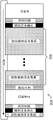
Turning now to the drawings, fig. 1 illustrates a block diagram of an exemplary capacitive input device (100) in accordance with an embodiment of the present disclosure. The capacitive input device (100) may be configured to provide input to an electronic system (not shown for simplicity). The term "electronic system" broadly refers to any system capable of electronically processing information. Some non-limiting examples of electronic systems include personal computers of all sizes and shapes, such as desktop computers, laptop computers, netbook computers, tablets, web browsers, e-book readers, and cellular telephones. Other examples include automotive user interfaces configured to give the driver user interface capabilities. Additionally, the electronic system may be a master or a slave to the capacitive input device.
The capacitive input device (100) may be implemented as a physical part of an electronic system. In the alternative, the capacitive input device (100) may be physically separate from the electronic system. The capacitive input device (100) may be coupled to (and in communication with) components of an electronic system using various wired or wireless interconnections and communication techniques.
In the example of fig. 1, the capacitive input device (100) may correspond to a proximity sensor device (such as a touch screen or any other touch sensor device) configured to sense input provided by one or more input objects (140) in the sensing region (120). Example input objects include fingers and styli. An example of a stylus is an active pen. The active pen moves across the sensing region and transmits a transmitter signal for detecting the position of the active pen and determining additional information. An example of an active pen is a USI pen (e.g., a USI stylus). In general, USI (universal stylus alliance) defines a standard for interoperable communication between a pen and touch-enabled devices, such as tablet computers and telephones.
Continuing with fig. 1, the sensing region (120) may encompass any space above, around, in, and/or near the capacitive input device (100) where the capacitive input device (100) is capable of detecting user input (e.g., provided by one or more input objects (140)). The size, shape, and location of a particular sensing region may vary depending on the actual implementation.
In some embodiments, the sensing region (120) extends in one or more directions into space from a surface of the capacitive input device (100), e.g., until a signal-to-noise ratio falls below a threshold suitable for object detection. For example, in various embodiments, the distance to which the sensing region (120) extends in a particular direction may be on the order of less than a millimeter, millimeters, centimeters, or more, and may vary with the type of sensing technology used and/or the accuracy desired. In some embodiments, the sensing region (120) detects input that involves no physical contact with any surface of the capacitive input device (100), contact with an input surface (e.g., a touch surface) of the capacitive input device (100), contact with an input surface of the capacitive input device (100) that is coupled with an amount of applied force or pressure, and/or combinations thereof.
In various embodiments, the input surface may be provided by a surface of an enclosure of the capacitive input device (100) within which the sensor electrodes reside, by a panel or any casing applied over the sensor electrodes, or the like. In some embodiments, the sensing region (120) has a rectangular shape when projected onto an input surface of the capacitive input device (100).
In some embodiments, the capacitive input device (100) may utilize capacitive sensing techniques to detect user input. For example, the sensing region (120) may input one or more capacitive sensing elements (e.g., sensor electrodes) to create an electric field. The capacitive input device (100) may detect an input based on a change in capacitance of the sensor electrode. More specifically, an object in contact with (or in close proximity to) the electric field may cause a change in voltage and/or current in the sensor electrodes. Such a change in voltage and/or current may be detected as a "signal" indicative of a user input. The sensor electrodes may be arranged in an array or other regular or irregular pattern of capacitive sensing elements to create an electric field. In some implementations, some sensing elements can be ohmically shorted together to form larger sensor electrodes. Some capacitive sensing techniques may utilize resistive patches that provide a uniform resistive layer.
The transcapacitive sensing method detects changes in capacitive coupling between sensor electrodes. For example, an input object (140) near the sensor electrodes may alter the electric field between the sensor electrodes, thereby changing the measured capacitive coupling of the sensor electrodes. In some embodiments, the capacitive input device (100) may enable transcapacitive sensing by detecting capacitive coupling between one or more transmitter sensor electrodes (also referred to as "transmitter electrodes" or "transmitters") and one or more receiver sensor electrodes (also referred to as "receiver electrodes" or "receivers"). The signal on the transmitter sensor electrode may be modulated relative to a reference voltage (e.g., system ground) to transmit a transmitter signal, while the receiver sensor electrode may be held at a substantially constant voltage relative to the reference voltage to receive a resulting signal. The reference voltage may be a substantially constant voltage or may be a system ground. The resulting signal may be affected by environmental interference (e.g., other electromagnetic signals) as well as input objects in contact with or in close proximity to the sensor electrodes. The sensor electrodes may be dedicated transmitters or receivers, or may be configured to both transmit and receive. Measurements taken using a mutual capacitance sensing method may be referred to as mutual capacitance measurements.
Furthermore, the sensor electrodes may have different shapes and/or sizes. The same shape and/or size of the sensor electrodes may or may not be in the same group. For example, in some embodiments, the receiver electrodes may have the same shape and/or size, while in other embodiments, the receiver electrodes may be different shapes and/or sizes.
The processing system (110) may be configured to operate hardware of the capacitive input device (100) to detect input in the sensing region (120). The processing system (110) may include part or all of one or more Integrated Circuits (ICs) and/or other circuit components and firmware. In some embodiments, the processing system (110) may include processing circuitry (150) configured to determine when at least one input object (140) is in the sensing region (120), determine whether the input object (140) is a stylus, determine a signal-to-noise ratio, determine positional information of the input object (140), identify a gesture, determine an action to perform based on the gesture, a combination of gestures, or other information, and/or perform other operations. In some embodiments, the processing system (110) may include a sensor circuit (160), the sensor circuit (160) configured to drive the sensing element to transmit the emitter signal and receive the resulting signal. In some embodiments, the sensor circuitry (160) may include sensor circuitry coupled to the sensor electrodes.
In some embodiments, the capacitive input device (100) includes a touch screen interface, and the sensing region (120) overlaps at least a portion of a working area of the display screen. For example, the capacitive input device (100) may include substantially transparent sensor electrodes overlying a display screen and provide a touch screen interface for an associated electronic system. The display screen may be any type of dynamic display capable of displaying a visual interface to a user. The capacitive input device (100) and the display screen may share physical elements. For example, some embodiments may utilize some of the same electrical components for display and sensing. In various embodiments, one or more display electrodes of a display device may be configured for both display updating and input sensing. As another example, the display screen may be partially or fully operated by the processing system (110).
While fig. 1 shows a configuration of components, other configurations may be used without departing from the scope of the present disclosure. For example, various components may be combined to create a single component. As another example, functionality performed by a single component may be performed by two or more components.
Fig. 2, 3, and 4 illustrate example capacitive input devices having capacitive communication channels for auxiliary devices. A capacitive communication channel is a communication channel in which a data signal is transmitted by modifying the electric field on one set of electrodes and detecting a change in capacitance on the other set of electrodes. In this application, electrode groups refer to sensing electrodes on the input device and auxiliary device electrodes on the auxiliary device.
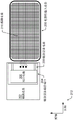
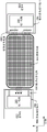
In this example, the capacitive input device (200) is a mobile device, such as a mobile phone or a tablet computer, which comprises a touch screen (not shown). Other capacitive input devices may be similarly configured to perform capacitive communication with an auxiliary device.
In this example, the capacitive input device (200) includes a sensing electrode (210), which is shown in fig. 2 as a grid. The capacitive sensing electrode is the sensing electrode described above with reference to fig. 1. In fig. 2, although the capacitive sensing electrodes are shown as a grid, any arrangement, size, shape, or type of capacitive sensing electrodes may be used. For example, the sensing electrodes may be arranged in a sensing pattern having a separate sensor electrode at each intersection of the grid, rather than rows and columns of sensor electrodes. In another example, the sensing electrodes may be arranged in a single layer of electrodes.
The capacitive input device (200) is configured to be capacitively coupled to the auxiliary device (202). Further, the capacitive input device may be physically attached to the auxiliary device so as to be stationary relative to the auxiliary device during use of the capacitive input device. Thus, with respect to the auxiliary device, the capacitive input device is an attached capacitive input device, and with respect to the capacitive input device, the auxiliary device is an attached auxiliary device. In one or more embodiments, the attachment is temporary such that the end user can detach the auxiliary device from the capacitive input device. Further, attachment may be performed using a connection mechanism, which may be a mechanical retainer (e.g., a wire harness, a clip, a strap, or other mechanical connection type), magnetic (e.g., using magnets of opposite polarity, etc.), or other connection mechanism. For example, the holder may be a tab (tab) or other mechanism as the accessory device wraps around the capacitive input device. For example, the auxiliary device may be a smart cover (cover) for a capacitive input device. In such an example, the auxiliary device may at least partially surround the capacitive input device, and the holder is a mechanism that holds the auxiliary device around. Further, the connection mechanism may be configured to hold the auxiliary device (202) stationary with respect to the capacitive input device (200). Thus, the auxiliary device (202) remains in a fixed position when used with a capacitive input device.
The auxiliary device (202) is an input device configured to detect input from a user. The auxiliary device (202) may comprise an input element (not shown) for detecting an input. An input element is a physical mechanism for receiving input. Example input elements include buttons, joysticks, wheels, dials, a set of directional buttons, payment card slots, near field communication ports for payment, touch screens, capacitive or resistive electrodes, and other types of physical mechanisms.
Example auxiliary devices include a game controller, a dial on a front face of a capacitive input device, an enclosure for a capacitive input device that extends the functionality of a capacitive input device, a payment device, or another type of auxiliary device for receiving input. The auxiliary device may be an extension of a smart phone that converts the smart phone into a flip phone. As another example, the secondary device may be a smart case for a mobile device that adds buttons to the mobile device to create additional ways for the user to communicate with the mobile device.
In one or more embodiments, the auxiliary device (202) includes an auxiliary device communication port (204). The auxiliary device communication port (204) is a communication port for capacitive-based communication. Other ports for electromagnetic communication may be present on the auxiliary device (202), such as radio-based communication ports and wired ports. The accessory communication port (204) includes a port circuit (206) and an accessory electrode (208). The port circuit (206) is a circuit configured to encode data from an input element of the auxiliary device (202) into a signal for capacitive communication. The data in the data stream may include binary data (e.g., open/closed switches) and digitized measurements (e.g., force/pressure). The port circuit (206) is further configured to transmit a signal on the auxiliary device electrode (208).
On the receiver side, the port circuit (206) comprises functionality to receive the resulting signal via the auxiliary device electrode (208) and decode the resulting signal. The resulting signal is generated from a transmitter signal on a transmitter electrode of the capacitive input device (200). The port circuit (206) may also be configured to transmit the decoded signal to a processor of the auxiliary device (202).
The auxiliary device electrode (208) may have the same functionality as the sensing electrode discussed above with reference to fig. 1. In particular, the auxiliary device electrodes may be receiver electrodes and transmitter electrodes. The same auxiliary device electrode may be both the receiver electrode and the transmitter electrode. Alternatively, a dedicated subset of the auxiliary device electrodes may be receiver electrodes, while another dedicated subset is transmitter electrodes.
Capacitive input devices and auxiliary devices may use various techniques to encode data into signals that may be transmitted capacitively. The capacitive input device and the auxiliary device have predefined techniques for encoding data, and in one or more embodiments the same technique is used. For example, the technique may be Binary Phase Shift Keying (BPSK), amplitude modulation, phase modulation, and/or frequency modulation.
The capacitive input device has a short axis and a long axis as shown by the coordinate definition (212). The length of the capacitive input device along the minor axis is shorter than the length of the capacitive input device along the major axis. Further, the major axis and the minor axis are perpendicular to each other and parallel to the input surface of the capacitive input device. For example, the major and minor axes may be along the sides of the display screen.
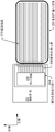
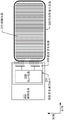
Different capacitive couplings may be used between the auxiliary device (202) and the capacitive input device (200). Fig. 3 and 4 show different configurations with different corresponding capacitive couplings (indicated by the dashed lines of fig. 2, 3 and 4). In the configuration of fig. 3, the auxiliary device communication port (204) has an auxiliary device electrode (208), the auxiliary device electrode (208) capacitively coupling with a sense electrode aligned perpendicular to a side to which the auxiliary device (202) is adjacent. The attached auxiliary device is attached to a side of the capacitive input device along the short axis, and the sensing electrode and the auxiliary device electrode are perpendicular to the short axis. More generally, the auxiliary device electrodes are perpendicular to the side of the capacitive input device where the auxiliary device is attached.
In the configuration of fig. 4, the auxiliary device communication port (204) has an auxiliary device electrode (208) capacitively coupled with at least one sense electrode aligned parallel to the side to which the auxiliary device (202) is adjacent. An attached auxiliary device is attached to a side of the capacitive input device along the minor axis, and the sensing electrode and the auxiliary device electrode are parallel to the minor axis. More generally, the auxiliary device electrode is parallel to the side of the capacitive input device where the auxiliary device is attached.
The difference between the respective configurations of fig. 3 and 4 is the capacitive coupling between the auxiliary device electrodes of the auxiliary device (202) and the sensing electrodes of the capacitive input device (200) versus throughput. In fig. 3, there are more communication channels between the capacitive input device and the port circuit (206) because more sensing electrodes are adjacent to the auxiliary device. Thus, greater data throughput may be achieved over the configuration of fig. 3 as compared to fig. 4. In fig. 4, although fewer sense electrodes are adjacent, a larger portion of the sense electrodes are adjacent. Thus, there is greater capacitive coupling between the electrodes in fig. 4 as compared to fig. 3. Thus, the configuration of fig. 3 may allow for greater data bandwidth (e.g., increased responsiveness of a user interface for an electronic system), while the configuration of fig. 4 may allow for greater spacing between the auxiliary device electrodes and the sense electrodes. For example, in one or more embodiments, fig. 3 may allow for about 2 to 3 millimeters or up to 10 millimeters between electrodes, while fig. 4 may allow for a gap of 10 to 15 millimeters. Other gaps are possible without departing from the scope of the present disclosure.
Although fig. 2-4 show the shorter side of the capacitive input device (200) adjacent to the auxiliary device (202), the longer side, front side, or back side of the capacitive input device (200) may be adjacent to the auxiliary device (202). In each configuration, at least one sensing electrode of the capacitive input device (200) is adjacent to at least one auxiliary device electrode (208) of the auxiliary device. For example, if on the back side, the sensing electrode may be a floating electrode, a zero-dimensional button electrode, a fingerprint sensor, or other configuration.
In one or more embodiments, the capacitive input device includes functionality to operate in one of two modes (a touch sensing mode and an auxiliary device mode). In touch sensing mode, the capacitive input device performs proximity sensing (e.g., detects input objects in a sensing region). In the auxiliary device mode, the capacitive input device performs capacitive communication with the auxiliary device. The difference between the two modes is as follows.
In touch sensing mode, the resulting signal reflects the position of an input object on the sensing region. To identify the location of the input object, a resulting signal is acquired. Various filtering is performed on the resulting signal to remove noise. The position of the input object may be determined based on peaks in the resulting signals from the different sensor electrodes.
In the auxiliary device mode, the auxiliary device is stationary. Thus, the resulting signal has only encoded data and noise at the particular electrode, as there is no signal caused by movement of the auxiliary device. Once the filtering is performed to remove the influence of noise, the encoded data is decoded to obtain data. The data may then be transferred to an electronic system to perform the resulting action.
Another difference between the different modes is whether the transmitter signal is known to the input device. The capacitive input device may identify the auxiliary device by a protocol. As shown in fig. 5, in the touch sensing mode (502), the transmitter signal is transmitted on the transmitter electrodes Tx (504) of the touch screen (506) and separately sent to the mixer (510) via traces (508) (not explicitly shown). Receiver electrode Rx (512) receives the resulting signal via capacitive coupling (514) and sends the resulting signal to mixer (510). The mixer (510) demodulates the resulting signal using the transmitter signal and sends the result to an analog-to-digital converter (ADC in fig. 5).
In the auxiliary device mode (516), the transmitter electrode (504) is not used to receive signals. In contrast, in the auxiliary device mode (516), the auxiliary device (518) has a transmitter electrode Tx (520) proximate to the receiver electrode (512) of the touchscreen (506). The proximity creates a capacitive coupling (524) between the transmitter electrode (520) and the receiver electrode (512). The receiver electrode (512) is coupled to the mixer (510) to pass the resulting signal to the mixer (510). However, the transmitter signal (526) is unknown to the mixer (510). Thus, the mixer (510) performs in-phase and quadrature (I/Q) demodulation on the resulting signal.
Mode switching may be performed using various techniques. In some embodiments, switching between modes is performed by the capacitive input device periodically transmitting a signal to detect the auxiliary device. When the auxiliary device responds, the capacitive input device may switch to the auxiliary device mode. Once in the auxiliary device mode, the capacitive input device may be periodically switched between the touch mode and the auxiliary device mode to receive data from the auxiliary device and detect touch input. The switching may be within a defined number of microseconds undetectable by the user.
As another example, when the capacitive input device switches to the auxiliary device mode, the capacitive input device may remain in the auxiliary device mode until the auxiliary device stops transmitting for a threshold amount of time or until a command is received to perform the switch with the aid of data in the capacitive communication channel. Other techniques for performing mode switching may be used without departing from the scope of this disclosure.
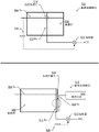
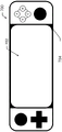
Fig. 6 and 7 show examples of using capacitive communication channels for two auxiliary devices. As shown in fig. 6, sense electrode (600) may be in communication with two auxiliary devices, e.g., device X (602) and device Y (604). Communication with device X (602) is performed using the configuration of fig. 3, while communication with device Y (604) is performed using the configuration of fig. 4. Specifically, the left-side auxiliary device electrode (606) has been configured for maximum bandwidth by eight auxiliary device electrodes designed to couple with eight long sensing electrodes (600) of the long axis. The coupling of the left side auxiliary device electrode (606) requires a higher voltage to make the signal-to-noise ratio equivalent to the right side auxiliary device electrode (608), which is optimized for low power. As an example, the right ancillary device electrode (608) may operate with a single 1.5V power supply because the surface area for coupling is much larger. Further, on the right side, one of the sensing electrodes (600) of the short axis is coupled with both Tx and Rx portions of the auxiliary device electrode (608). When the mobile device transmits with the sensing electrode (600) on the right, two portions of the auxiliary device electrode (608) are driven. In the coupling region on the right, the auxiliary device (i.e., device Y (604)) has two electrodes, which can be dynamically configured by the device as any combination of receiver/transmitter.
The example of fig. 6 is shown in fig. 7. In fig. 7, the system with two auxiliary devices is a game controller (700) for use with a mobile device. As shown by the white outline (702), the mobile device may be a mobile phone with a touch screen. The harness (704) holding the game controller stationary is the cradle (cradle) for the game controller of the mobile device. The mobile device executes and displays a game that the user can play using the game controller. Communication between the mobile device and the game controller is accomplished through a capacitive communication channel as shown in fig. 6. In the multi-channel version, the mobile device appears to be more responsive. With game controllers, a user typically has hands on both sides of the game controller. However, the user can switch by touching the touch screen. In this case, the capacitive mobile device switches to a touch screen mode. By using capacitive communication, the ports of the mobile device and game controller can be used for other purposes, such as connecting to audio input/output devices.
For the game console (700), the centralized controller of the game console may bundle user input from both sides into a single payload. The payload may be transferred over a single capacitive coupling link. In the case of two or more connection aids, two or more devices may be paired with separate electrodes. Other techniques may be used without departing from the scope of this disclosure.
Another aspect of the invention is the management of the frame budget for the capacitive sensing frame of the capacitive input device. As described above, the capacitive input device may operate in an auxiliary device mode, a touch screen mode, or a combined mode. In the secondary device mode, the frame budget is optimized for high sampling rates and low delays of data from the secondary device. During the auxiliary device mode, the capacitive input device operates in a sleep mode to check for any nearby input objects in the sensing region at low frequencies. If a proximity input object is detected, the capacitive input device switches to a touch screen mode. The touch screen mode facilitates scanning a finger. The system will also support a conventional USI pen. The combination mode refers to repeatedly switching between the auxiliary device mode and the touch screen mode in a single frame.
Fig. 8 is an example of a communication timing diagram (800) that can be modified to operate a capacitive communication channel in accordance with one or more embodiments.
Initiating communication with the secondary device may be performed as follows. When in the touch screen mode, the capacitive input device periodically transmits beacon signals (represented in fig. 8 as beacon N and beacon N + 1). If no response occurs, the capacitive input device continues to perform touch screen mode based sensing. Sensing based on the touch screen mode means that the sensing circuit drives at least a part of the sensing electrodes with a sensing signal and receives a resulting signal resulting from capacitive coupling between the sensing signal and the sensing electrodes. The resulting signal may be a modified version of the sensing signal based on the noise and any input objects present in the sensing region. Based on the resulting signal, position information of any current input object is determined.
Returning to fig. 8 and the beacon signal, if an auxiliary device is present, the auxiliary device responds to the beacon signal and the capacitive input device with an auxiliary device acknowledgement. The auxiliary device confirmation may include identification information (e.g., a device code, such as a product code, that uniquely identifies the type of auxiliary device). The capacitive input device may then use the identification information to gather device information for the auxiliary device. The device information may include information for decoding data received from the auxiliary device, the number and type of input elements, and the like. At this stage, the input device is configured to receive and decode data from the auxiliary device. The auxiliary device obtains input from a user via the input element, processes the input to obtain data, and encodes the data into a data signal for transmission to the capacitive input device. The capacitive input device receives auxiliary device data as a data signal during time (802) and decodes the data to obtain decoded data. At the end of time (802), a hangover time may be added for the capacitive input device to complete receiving the encoded data. Because the auxiliary device is temporarily attached and can be detached at any time, the capacitive input device can periodically transmit a beacon signal at a predefined frequency to resume processing. This process may be repeated with beacon N +1 regardless of whether the secondary device is detached to continue communication. Although not shown, the communication may be bidirectional communication by adding information in a beacon signal or adding a period of time (not shown) in a timing chart.
Fig. 9 is an example of a communication timing diagram (900) modified to operate a capacitive communication channel in accordance with one or more embodiments. In the timing diagram of FIG. 9, the data packet is interleaved with touch sensing during time (902). In particular, the drive and receive result signals of the transmit sense electrodes on the capacitive input device are interleaved with the receive data signals from the auxiliary device. Thus, using the configuration of FIG. 9, a user may use both the touch input and the auxiliary device at the same time. In this example, the capacitive input device switches between modes during a single frame.
Whether the timing diagram of FIG. 8 or FIG. 9 is predefined for use between the capacitive input device and the auxiliary device. One method of enabling communication between an auxiliary device and a capacitive input device is to reuse the universal stylus alliance (USI) standard for auxiliary devices.
In some embodiments, because the mobile device is stationary relative to the capacitive input device, the beacons may be ignored or used only periodically.
The use of a capacitive communication channel may provide lower latency, faster update rates, lower power consumption, and lower cost for auxiliary devices such as game consoles attached to smart phones. The touch controller can interact with the auxiliary device through a capacitive channel to transmit user interactions to the host processor and application. Further, one or more embodiments may use time-slicing for the communication mode, including capacitive communication. For example, one or more embodiments may be used where the capacitive input device does not have a physical port (e.g., a Universal Serial Bus (USB) port). Further, one or more embodiments may be used to replace and/or supplement bluetooth connections.
Thus, the embodiments and examples set forth herein are presented to best explain various embodiments and specific applications and to thereby enable those skilled in the art to make and use the invention. Those skilled in the art, however, will recognize that the foregoing description and examples have been presented for the purpose of illustration and example only. The description as set forth is not intended to be exhaustive or to limit the invention to the precise form disclosed.
Claims (20)
1. A capacitive input device, comprising:
a first plurality of sense electrodes configured to form a first capacitive coupling with a first plurality of auxiliary device electrodes of a first attached auxiliary device,
wherein the first plurality of auxiliary device electrodes transmit data signals to the first plurality of sense electrodes via the first capacitive coupling; and
a processing circuit configured to decode the data signal received via the first capacitive coupling to obtain decoded data.
2. The capacitive input device of claim 1, wherein:
the first plurality of sense electrodes extend along a direction perpendicular to a side of the capacitive input device adjacent to the first attachment aid.
3. The capacitive input device of claim 1, wherein:
the first plurality of sense electrodes extend along a direction parallel to a side of the capacitive input device adjacent to the first attachment aid.
4. The capacitive input device of claim 1, further comprising:
a second plurality of sense electrodes different from the first plurality of sense electrodes, the second plurality of sense electrodes configured to form a second capacitive coupling with a second plurality of auxiliary device electrodes of a second attached auxiliary device.
5. The capacitive input device of claim 1, further comprising:
a second plurality of sense electrodes forming a second capacitive coupling with the first plurality of sense electrodes; and
a sensing circuit coupled to the first plurality of sensing electrodes and the second plurality of sensing electrodes, the sensing circuit configured to:
driving a third plurality of sense electrodes with a sense signal,
receiving, from the first plurality of sense electrodes, a resulting signal resulting from the sense signal and the second capacitive coupling.
6. The capacitive input device of claim 5, wherein the sensing circuit is further configured to:
receiving the data signal via the first capacitive coupling,
wherein the receiving of the data signal is interleaved with the driving of the third plurality of sense electrodes and receiving the result signal.
7. The capacitive input device of claim 5, wherein the capacitive input device comprises a touch screen defining a sensing region, and wherein the processing circuit is further configured to:
determining positional information for input objects in the sensing region from the resulting signals,
wherein the input object is different from the first attachment aid.
8. The capacitive input device of claim 1, wherein the capacitive input device is configured to:
transmitting a beacon signal using a plurality of electrodes including the first plurality of sensing electrodes,
receiving an auxiliary device acknowledgement for the first attached auxiliary device, an
Modifying a timing of driving a second plurality of sense electrodes based on receiving the secondary device acknowledgement.
9. The capacitive input device of claim 8, wherein modifying the timing comprises ceasing to drive the second plurality of sense electrodes in order to receive the data signal.
10. The capacitive input device of claim 8, wherein modifying the timing comprises interleaving driving the second plurality of sense electrodes and receiving resulting signals with receiving the data signals.
11. A system comprising a first auxiliary device, the first auxiliary device comprising:
a first input element configured to receive a first input from a user;
a first processing component coupled to the first input element and configured to process the first input to obtain first data; and
a first port circuit coupled to the first processing component and comprising a first plurality of auxiliary device electrodes configured to form a first capacitive coupling with a first plurality of sense electrodes of an attached capacitive input device,
the first port circuit is configured to drive the first plurality of auxiliary device electrodes with a first data signal encoding the first data.
12. The system of claim 11, wherein the first auxiliary device is a game controller.
13. The system of claim 11, further comprising:
a second auxiliary device comprising:
a second input element configured to receive a second input from the user,
a second processing component coupled to the second input element and configured to process the second input to obtain second data, an
A second port circuit coupled to the second processing component and comprising a second plurality of auxiliary device electrodes configured to form a second capacitive coupling with a second plurality of sense electrodes of the attached capacitive input device,
the second port circuit is configured to drive the second plurality of auxiliary device electrodes with a second data signal encoding the second data,
wherein the first plurality of sense electrodes and the second plurality of sense electrodes are different electrodes.
14. The system of claim 11, further comprising:
a harness for attaching the first and second auxiliary devices to both sides of the attached capacitive input device.
15. The system of claim 11, wherein the first auxiliary device is a payment device.
16. A method, comprising:
attaching a first auxiliary device to the capacitive input device;
receiving, by the capacitive input device, a first input from a first input element of the first auxiliary device;
generating a first data signal from the first input; and
transmitting a first data signal via a first capacitive coupling between a first plurality of auxiliary device electrodes on the first auxiliary device and a first plurality of sensor electrodes on the capacitive input device.
17. The method of claim 16, further comprising:
receiving a beacon signal from the capacitive input device, an
Responding to the beacon signal with an auxiliary device acknowledgement.
18. The method of claim 16, further comprising:
attaching a second auxiliary device to the capacitive input device;
receiving, by the capacitive input device, a second input from a second input element of the second auxiliary device;
generating a second data signal from the second input; and
transmitting a second data signal via a second capacitive coupling between a second plurality of auxiliary device electrodes on the second auxiliary device and a second plurality of sensor electrodes on the capacitive input device.
19. The method of claim 18, wherein the transmission of the first data signal and the second data signal is performed simultaneously.
20. The method of claim 16, wherein the first auxiliary device is a game controller.
Applications Claiming Priority (4)
| Application Number | Priority Date | Filing Date | Title |
|---|---|---|---|
| US202163211339P | 2021-06-16 | 2021-06-16 | |
| US63/211339 | 2021-06-16 | ||
| US17/738619 | 2022-05-06 | ||
| US17/738,619 US20220404940A1 (en) | 2021-06-16 | 2022-05-06 | Capacitive communication channel for auxiliary devices |
Publications (1)
| Publication Number | Publication Date |
|---|---|
| CN115480667A true CN115480667A (en) | 2022-12-16 |
Family
ID=84422764
Family Applications (1)
| Application Number | Title | Priority Date | Filing Date |
|---|---|---|---|
| CN202210679576.XA Pending CN115480667A (en) | 2021-06-16 | 2022-06-16 | Capacitive communication channel for auxiliary devices |
Country Status (3)
| Country | Link |
|---|---|
| US (1) | US20220404940A1 (en) |
| JP (1) | JP2022192019A (en) |
| CN (1) | CN115480667A (en) |
-
2022
- 2022-05-06 US US17/738,619 patent/US20220404940A1/en active Pending
- 2022-06-03 JP JP2022090692A patent/JP2022192019A/en active Pending
- 2022-06-16 CN CN202210679576.XA patent/CN115480667A/en active Pending
Also Published As
| Publication number | Publication date |
|---|---|
| US20220404940A1 (en) | 2022-12-22 |
| JP2022192019A (en) | 2022-12-28 |
Similar Documents
| Publication | Publication Date | Title |
|---|---|---|
| CN111665967B (en) | Method for executing in active pen and active pen | |
| US9958966B2 (en) | Active stylus communication and position system | |
| US9841862B2 (en) | Stylus position system | |
| CN111538422B (en) | Activation pen and input system | |
| WO2012039837A1 (en) | Capacitive stylus for a touch screen | |
| US10031590B2 (en) | Active stylus with a parallel communication channel | |
| CN103389804A (en) | Coordinate indication device and coordinate measurement device for measuring input position of the coordinate indication device | |
| WO2019113060A1 (en) | Active stylus apparatus and method | |
| US11169626B2 (en) | Transmitter, touch sensitive processing apparatus and processing method thereof and electronic system | |
| US20210157428A1 (en) | Minimizing latency for resonant input object detection and classification | |
| US20220404940A1 (en) | Capacitive communication channel for auxiliary devices | |
| US20220357812A1 (en) | Low ground mass mitigation for pens | |
| US11928271B1 (en) | Capacitive knob sensing system and method to detect initial states | |
| CN114489395B (en) | Signal transmission method and device, touch chip and electronic equipment | |
| TW202331476A (en) | Stylus control circuit and stylus | |
| CN116610228A (en) | Control circuit, electronic device and control method |
Legal Events
| Date | Code | Title | Description |
|---|---|---|---|
| PB01 | Publication | ||
| PB01 | Publication |