CN115447368A - Engine mounting and vehicle - Google Patents
Engine mounting and vehicle Download PDFInfo
- Publication number
- CN115447368A CN115447368A CN202211231598.6A CN202211231598A CN115447368A CN 115447368 A CN115447368 A CN 115447368A CN 202211231598 A CN202211231598 A CN 202211231598A CN 115447368 A CN115447368 A CN 115447368A
- Authority
- CN
- China
- Prior art keywords
- limiting
- upper seat
- limiting plate
- main spring
- hollow cavity
- Prior art date
- Legal status (The legal status is an assumption and is not a legal conclusion. Google has not performed a legal analysis and makes no representation as to the accuracy of the status listed.)
- Pending
Links
Images


Classifications
-
- B—PERFORMING OPERATIONS; TRANSPORTING
- B60—VEHICLES IN GENERAL
- B60K—ARRANGEMENT OR MOUNTING OF PROPULSION UNITS OR OF TRANSMISSIONS IN VEHICLES; ARRANGEMENT OR MOUNTING OF PLURAL DIVERSE PRIME-MOVERS IN VEHICLES; AUXILIARY DRIVES FOR VEHICLES; INSTRUMENTATION OR DASHBOARDS FOR VEHICLES; ARRANGEMENTS IN CONNECTION WITH COOLING, AIR INTAKE, GAS EXHAUST OR FUEL SUPPLY OF PROPULSION UNITS IN VEHICLES
- B60K5/00—Arrangement or mounting of internal-combustion or jet-propulsion units
- B60K5/12—Arrangement of engine supports
- B60K5/1208—Resilient supports
Landscapes
- Engineering & Computer Science (AREA)
- Chemical & Material Sciences (AREA)
- Combustion & Propulsion (AREA)
- Transportation (AREA)
- Mechanical Engineering (AREA)
- Vibration Prevention Devices (AREA)
Abstract
The invention relates to an engine suspension and a vehicle, wherein the engine suspension comprises a shell, an upper seat and main spring rubber, and a hollow cavity is formed in the middle of the shell; the upper seat is used for supporting the engine suspension bracket and is arranged in the hollow cavity; the main spring rubber is arranged between the inner wall surface of the hollow cavity and the upper seat, and the main spring rubber is configured into an arch structure, so that the main spring rubber is connected with the rear end surface and the side surface of the upper seat close to the hollow cavity. Through the main spring rubber with the arch structure, the whole bearing volume of the main spring rubber is large, the rigidity of the main spring rubber can be reduced, and the vibration isolation performance of the main spring rubber is improved, so that the stability of the supporting engine is improved.
Description
Technical Field
The invention relates to the technical field of automobile suspensions, in particular to an engine suspension. In addition, the invention also relates to a vehicle comprising the engine suspension.
Background
The engine suspension of the automobile can support the engine, simultaneously damp vibration transmission between the engine and the frame, and improve driving comfort of a driver. The existing engine suspension rubber is generally of a block structure, and has small volume, high rigidity and poor vibration isolation performance, so that the engine cannot be stably and effectively supported, and the comfort of the whole vehicle is influenced.
Disclosure of Invention
In view of this, it is necessary to provide an engine mount for solving the problem that the engine cannot be stably supported.
An engine mount, comprising:
the middle part of the shell forms a hollow cavity;
the upper seat is used for supporting an engine suspension bracket, is arranged in the hollow cavity and is provided with a rear end face facing the inner wall surface of the hollow cavity and a side face connected to the rear end face;
the buffer piece is connected to the shell and at least partially located in the hollow cavity, and the buffer piece is simultaneously contacted with the rear end face and the side face.
In one embodiment, a limiting plate is arranged on the shell, and one end of the buffer piece, which is far away from the upper seat, is connected to the limiting plate.
In one embodiment, the limiting plate comprises a first limiting part and a second limiting part which are arranged at an included angle, the first limiting part is parallel to the rear end face, and the second limiting part is parallel to the side face.
In one embodiment, the hollow cavity is provided with a positioning inclined plane, the limiting plate is mounted on the positioning inclined plane, and the limiting plate is attached to the positioning inclined plane.
In one embodiment, a limiting groove is formed in the end portion of the positioning inclined plane in the longitudinal direction, the end portion of the limiting plate is arranged in the limiting groove, and the end portion of the limiting plate and the limiting groove are clamped and fixed in the longitudinal direction.
In one embodiment, the outer surface of the upper seat is provided with limiting rubber, and the inside of the hollow cavity is provided with a limiting plane;
the limiting rubber and the limiting plane are arranged in a clearance mode, and the limiting rubber and the limiting plane are configured to be used for limiting the deformation of the buffer piece.
In one embodiment, the bottom of the housing is provided with a retaining structure configured to restrict movement of the upper seat in a width direction thereof.
In one embodiment, the anti-disengaging structure is a cylindrical pin, and one end of the limiting plate connected with the buffer member is clamped and fixed with the cylindrical pin in the width direction of the upper seat.
In one embodiment, at least two of the cylindrical pins are arranged at the bottom of the shell.
A vehicle, comprising:
the engine mount as described above.
The engine suspension comprises a shell, an upper seat and main spring rubber, wherein a hollow cavity is formed in the middle of the shell, the upper seat is arranged in the hollow cavity, a buffer piece is arranged between the hollow cavity and the upper seat, and the buffer piece is connected with the rear end face and the side face of the upper seat.
During installation, the buffer part is connected with one end of the inner wall surface of the upper seat close to the hollow cavity, and the buffer part is connected with the rear end surface and the side surface of the upper seat at the same time, so that the buffer part wraps the rear end surface and the side surface of the upper seat close to the hollow cavity, and the connected upper seat and the buffer part are integrally installed in the hollow cavity.
The buffer piece is arranged and is simultaneously connected with the rear end face and the side face of the upper seat, the whole bearing volume of the buffer piece is large, the rigidity of the buffer piece can be reduced, the vibration isolation performance of the buffer piece is improved, and therefore the stability of the supporting engine is improved.
In addition, the invention also provides a vehicle comprising the engine mount, and the vehicle has the same beneficial effects as the engine mount because the vehicle is provided with the engine mount.
Drawings
FIG. 1 is a front view of an engine mount provided by the present invention;
FIG. 2 is a cross-sectional view of an engine mount provided by the present invention;
FIG. 3 is a side view of an engine mount provided by the present invention;
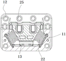
fig. 4 is a schematic structural view of a second assembly hole of the engine mount provided by the invention.
In the figure: 1. a housing; 2. a vibration damping body; 3. a cylindrical pin; 11. positioning the inclined plane; 12. a first fitting hole; 13. a limiting hole; 14. a limiting plane; 21. an upper seat; 22. main spring rubber; 23. a limiting plate; 24. limiting rubber; 25. a second assembly hole.
Detailed Description
In order to make the aforementioned objects, features and advantages of the present invention comprehensible, embodiments accompanied with figures are described in detail below. In the following description, numerous specific details are set forth in order to provide a thorough understanding of the present invention. This invention may, however, be embodied in many different forms and should not be construed as limited to the embodiments set forth herein, as those skilled in the art will recognize without departing from the spirit and scope of the present invention.
In the description of the present invention, it is to be understood that the terms "central," "longitudinal," "lateral," "length," "width," "thickness," "upper," "lower," "front," "rear," "left," "right," "vertical," "horizontal," "top," "bottom," "inner," "outer," "clockwise," "counterclockwise," "axial," "radial," "circumferential," and the like are used in the orientations and positional relationships indicated in the drawings for convenience in describing the invention and to simplify the description, and are not intended to indicate or imply that the referenced device or element must have a particular orientation, be constructed and operated in a particular orientation, and are not to be considered limiting of the invention.
Furthermore, the terms "first", "second" and "first" are used for descriptive purposes only and are not to be construed as indicating or implying relative importance or implicitly indicating the number of technical features indicated. Thus, a feature defined as "first" or "second" may explicitly or implicitly include at least one such feature. In the description of the present invention, "a plurality" means at least two, e.g., two, three, etc., unless specifically limited otherwise.
In the present invention, unless otherwise expressly stated or limited, the terms "mounted," "connected," "secured," and the like are to be construed broadly and can, for example, be fixedly connected, detachably connected, or integrally formed; can be mechanically or electrically connected; they may be directly connected or indirectly connected through intervening media, or they may be connected internally or in any other suitable relationship, unless expressly stated otherwise. The specific meanings of the above terms in the present invention can be understood according to specific situations by those of ordinary skill in the art.
In the present invention, unless otherwise expressly stated or limited, the first feature "on" or "under" the second feature may be directly contacting the first and second features or indirectly contacting the first and second features through an intermediate. Also, a first feature "on," "over," and "above" a second feature may be directly or diagonally above the second feature, or may simply indicate that the first feature is at a higher level than the second feature. A first feature "under," "beneath," and "under" a second feature may be directly under or obliquely under the second feature, or may simply mean that the first feature is at a lesser elevation than the second feature.
It will be understood that when an element is referred to as being "secured to" or "disposed on" another element, it can be directly on the other element or intervening elements may also be present. When an element is referred to as being "connected" to another element, it can be directly connected to the other element or intervening elements may also be present. The terms "vertical," "horizontal," "upper," "lower," "left," "right," and the like as used herein are for illustrative purposes only and do not denote a unique embodiment.
1-4, in some embodiments, the engine mount comprises a housing 1, an upper seat 21 and a main spring rubber 22, wherein a hollow cavity is formed in the middle of the housing 1; the upper seat 21 is used for supporting the engine suspension bracket, the upper seat 21 is arranged in the hollow cavity, and the upper seat 21 is provided with a rear end face facing the inner wall surface of the hollow cavity and a side face connected with the rear end face; the buffer piece is connected with the shell 1 and at least partially positioned in the hollow cavity, and the buffer piece is simultaneously contacted with the rear end face and the side face.
Specifically, the housing 1 is rectangular when viewed from the front, and is also rectangular when viewed from the side, because the housing 1 is internally provided with a hollow cavity, the side of the housing 1 in fig. 3 is L-shaped, the top of the housing 1 is provided with four first assembly holes 12, the bottom of the housing 1 is provided with two first assembly holes 12, the first assembly holes 12 are circular holes, the four first assembly holes 12 at the top of the housing 1 are uniformly arranged in the width direction of the housing 1, the two first assembly holes 12 at the bottom of the housing 1 are symmetrically arranged at two sides of the housing 1, and the middle of the housing 1 is of a hollow structure to form a hollow cavity; the top of the upper seat 21 is of a cuboid structure, the bottom of the upper seat 21 is integrally of a conical structure, the upper seat 21 is formed by combining the cuboid structure and the conical structure, and two second assembling holes 25 are formed in the top of the upper seat 21; the buffer member is main spring rubber 22, the main spring rubber 22 is arranged between the hollow cavity and the upper seat 21, the main spring rubber 22 is connected with the rear end face, the left side face and the right side face of the upper seat into a whole in a vulcanization mode, namely the main spring rubber 22 is integrally in an arch structure.
During installation, the main spring rubber 22 and the upper seat 21 which are vulcanized into a whole are installed in the hollow cavity, the shell 1, the main spring rubber 22 and the upper seat 21 are integrally connected with an automobile frame or an automobile body through six first assembly holes 12 on the shell 1, and the upper seat 21 is connected with an engine suspension bracket through a second assembly hole 25 on the top of the upper seat 21.
By arranging the main spring rubber 22 with the arch structure, the whole bearing volume of the main spring rubber 22 is large, the rigidity of the main spring rubber 22 can be reduced, and the vibration isolation performance of the main spring rubber 22 is improved, so that the stability of supporting an engine is improved, and the service life of the main spring rubber 22 and the engine suspension is prolonged.
Alternatively, the upper seat 21 may have another shape.
Alternatively, other numbers of first fitting holes 12 may be provided.
Alternatively, the first fitting hole 12 may be provided in other manners.
Alternatively, other numbers of second fitting holes 25 may be provided.
Optionally, the buffer may be a spring or other structure.
In some embodiments, a limiting plate 23 is disposed on the housing 1, and an end of the buffer far away from the upper seat 21 is connected to the limiting plate 23.
Specifically, one side of the main spring rubber 22 is connected with the rear end face, the left side face and the right side face of the upper seat 21, one side of the main spring rubber 22 close to the inner wall face of the hollow cavity is connected with the limiting plate 23, the limiting plate 23 and the main spring rubber 22 are also connected into a whole in a vulcanization mode, that is, the limiting plate 23, the main spring rubber 22 and the upper seat 21 are connected into a whole in a vulcanization mode, the whole is called as the vibration damping body 2, and the limiting plate 23 is connected with the main spring rubber 22, so that the whole limiting plate 23 is also in an arch structure.
When the device is installed, the main spring rubber 22, the limiting plate 23 and the upper seat 21 are connected into a whole in a vulcanization mode, and then the main spring rubber 22, the limiting plate 23 and the upper seat 21 are installed in the hollow cavity together.
Because main spring rubber 22 self has stronger deformability, consequently install in the cavity after being connected main spring rubber 22 and limiting plate 23, accessible limiting plate 23 provides more stable holding power for main spring rubber 22, avoids main spring rubber 22 self installation unstability and leads to seat 21 to rock, avoids main spring rubber 22 self installation unstability to lead to unable stable resilience force of providing for seat 21 simultaneously.
Alternatively, the limiting plate 23 of the whole arch structure may be connected to the main spring rubber 22, or the limiting plates 23 of a plurality of other shapes and structures may be connected to the main spring rubber 22.
In some embodiments, the position-limiting plate 23 includes a first position-limiting portion and a second position-limiting portion, which are disposed at an included angle, the first position-limiting portion is parallel to the rear end surface, and the second position-limiting portion is parallel to the side surface.
Specifically, the limiting plate 23 includes a second limiting portion on the left side, a first limiting portion in the middle, and a second limiting portion on the right side, which are connected to form an arched limiting plate 23, the second limiting portion on the left side of the upper seat 21 is arranged in parallel with the left side surface of the conical structure at the bottom of the upper seat 21, that is, the second limiting portion on the left side and the left side surface of the conical structure of the upper seat 21 are inclined surfaces with the same inclination degree; the first limiting part positioned at the rear side of the upper seat 21 is arranged in parallel with the rear end surface of the conical structure at the bottom of the upper seat 21, namely the middle first limiting part and the rear end surface of the conical structure of the upper seat 21 are inclined planes with the same inclination degree; the second limiting part located on the right side of the upper seat 21 is parallel to the right side surface of the conical structure at the bottom of the upper seat 21, that is, the second limiting part on the right side and the right side surface of the conical structure of the upper seat 21 are inclined surfaces with the same inclination degree.
The limiting plate 23 is arranged to be parallel to the rear end face, the left side face and the rear side face of the conical structure of the upper seat 21, so that the supporting stability of the limiting plate 23 on the main spring rubber 22 and the upper seat 21 can be improved, the shaking degree of the upper seat 21 is further reduced, the vibration isolation performance of the main spring rubber 22 is improved, and the service lives of the engine suspension and the main spring rubber 22 are prolonged.
Optionally, the included angle between the first and second position-limiting parts is 60 ° to 120 °, for example, 65 °, 70 °, 75 °, 80 °, 90 °, 100 °, 110 ° may be specific.
Optionally, the first limiting portion and the second limiting portion are integrally formed to improve the structural strength of the limiting plate 23, so as to better support the buffer. For example, in one embodiment, the limiting plate 23 is formed by bending a sheet metal part.
Alternatively, the limiting plate 23 may be provided with slopes having different degrees of inclination from the rear end surface, the left side surface, and the right side surface of the conical structure of the upper seat 21.
In some embodiments, the hollow cavity is provided with a positioning inclined plane 11, the limiting plate 23 is installed on the positioning inclined plane 11, and the limiting plate 23 is attached to the positioning inclined plane 11.
Specifically, the lower end of the hollow cavity is provided with a positioning inclined plane 11, and the inclination degree of the positioning inclined plane 11 on the left side of the hollow cavity is the same as that of the second limiting part on the left side; the inclination degree of the positioning inclined plane 11 positioned in the middle of the hollow cavity is the same as that of the first limiting part in the middle; the inclined degree of the positioning inclined plane 11 on the right side of the hollow cavity is the same as the inclined degree of the second limiting part on the right side.
During installation, the limiting plate 23 is installed on the positioning inclined surface 11 according to the position of the positioning inclined surface 11, and the end face of the limiting plate 23, which is not connected with the main spring rubber 22, is attached to the positioning inclined surface 11.
Because main spring rubber 22 has certain deformability, and limiting plate 23 is connected with main spring rubber 22, therefore main spring rubber 22 can drive limiting plate 23 and remove to a certain extent, and set up location inclined plane 11 and can be convenient for limiting plate 23, main spring rubber 22 and the holistic installation of seat 21, the degree of inclination at each position of location inclined plane 11 is the same with the degree of inclination at each position of limiting plate 23 simultaneously, can guarantee that limiting plate 23 keeps the rear end face for with seat 21 toper structure when the installation, the left flank, the parallel state of right flank, thereby guarantee that limiting plate 23 and main spring rubber 22 support the stability of seat 21, improve limiting plate 23, seat 21 and main spring rubber 22's installation rate, and the work efficiency is improved.
Optionally, the inclination degree of the left side portion of the positioning inclined plane 11 may also be different from the inclination degree of the left second limiting portion; the inclination degree of the middle part of the positioning inclined plane 11 can be different from that of the middle first limiting part; the degree of inclination of the right-side portion of the positioning slope 11 may be different from the degree of inclination of the right-side second stopper portion.
In some embodiments, the positioning inclined plane 11 is provided with a limiting groove at an end in the longitudinal direction, the end of the limiting plate 23 is disposed in the limiting groove, and the end of the limiting plate 23 is fixed to the limiting groove in the longitudinal direction in a clamping manner.
Specifically, the upper end and the lower end of the left part of the positioning inclined plane 11 are both provided with a limiting groove, the upper end and the lower end of the left second limiting part are respectively arranged in the limiting grooves at the two ends, at the moment, the limiting groove and the left second limiting part are longitudinally clamped and connected, and the limiting groove and the left second limiting part are also clamped and fixed in the left-right direction; the upper end of the middle part of the positioning inclined plane 11 is provided with a limiting groove, the upper end of the middle first limiting part is arranged in the limiting groove, the limiting groove and the middle first limiting part are clamped and connected in the longitudinal direction at the moment, and the limiting groove and the middle first limiting part are also clamped and fixed in the left-right direction; the upper end and the lower end of the right side part of the positioning inclined plane 11 are both provided with a limiting groove, the upper end and the lower end of the second limiting part on the right side are respectively arranged in the limiting grooves at the two ends, the limiting groove and the second limiting part on the right side are connected in a clamping mode in the vertical direction, and the limiting groove and the second limiting part on the right side are connected in a clamping mode in the left-right direction.
Through the tip at location inclined plane 11 sets up the spacing groove, and make limiting plate 23 and spacing groove vertically with left right direction go up the joint fixed, thereby can restrict seat 21, main spring rubber 22 and limiting plate 23 are vertical the removal, avoid seat 21, main spring rubber 22 and the cavity is deviate from the top to the whole of limiting plate 23, the spacing groove can restrict limiting plate 23 and move about in the direction simultaneously, thereby guarantee that limiting plate 23 can the stable support main spring rubber 22, further guarantee that main spring rubber 22 can stable support seat 21 and engine.
The edges of the limiting groove are arc-shaped, so that the main spring rubber 22 is prevented from being scratched by the edges of the limiting groove in the installation process, the upper seat 21 and the engine cannot be stably supported, and optionally, the edges of the limiting groove can be set into other shapes.
In some embodiments, the outer surface of the upper seat 21 is provided with a limiting rubber 24, and the inside of the hollow cavity is provided with a limiting plane 14;
the stopper rubber 24 is disposed at a gap from the stopper plane 14, and the stopper rubber 24 and the stopper plane 14 are configured to limit the amount of deformation of the buffer.
Specifically, the up end of seat 21, the left end face, the right-hand member face, bottom surface and rear end face all are equipped with spacing rubber 24, specifically be the up end of the cuboid structure of seat 21, the left end face, right-hand member face and rear end face are equipped with spacing rubber 24, and the bottom surface of the toper structure of seat 21 is equipped with spacing rubber 24, the left side of cavity in casing 1, the right side, the rear side, top and bottom all are equipped with spacing plane 14, and have certain clearance between spacing rubber 24 and the spacing plane 14, spacing rubber 24 is thinner, its compressive deformation volume of self can be neglected.
When the engine suspension bracket is installed on the upper seat 21, the upper seat 21 is driven by the pressure of the engine suspension bracket to move downwards, the main spring rubber 22 deforms, and when the limiting rubber 24 at the bottom of the upper seat 21 is contacted with the limiting plane 14 at the bottom of the hollow cavity, the limiting plane 14 is abutted against the upper seat 21, so that the upper seat 21 stops moving downwards, and the main spring rubber 22 stops deforming; similarly, when the upper seat 21 moves to the left side, the upper seat 21 stops moving until the limiting rubber 24 on the left end surface of the upper seat 21 contacts the limiting plane 14 on the left side of the hollow cavity; when the upper seat 21 moves towards the right side, the upper seat 21 stops moving until the limiting rubber 24 on the right end surface of the upper seat 21 contacts with the limiting plane 14 on the right side of the hollow cavity; when the upper seat 21 moves towards the rear side, the upper seat 21 stops moving until the limiting rubber 24 on the rear end surface of the upper seat 21 contacts with the limiting plane 14 on the rear side of the hollow cavity; when the upper seat 21 moves upwards, the upper seat 21 stops moving until the limiting rubber 24 on the upper end surface of the upper seat 21 contacts with the limiting plane 14 on the top of the hollow cavity.
Because the upper seat 21 cannot move continuously after the limiting rubber 24 is contacted with the limiting plane 14, the main spring rubber 22 cannot deform, namely, the gap distance between the limiting rubber 24 and the limiting plane 14 is the deformation of the main spring rubber 22, the deformation of the main spring rubber 22 is limited by the limiting rubber 24 and the limiting plane 14, namely, the movement range of the upper seat 21 and the engine suspension bracket is limited, so that the situation that the upper seat 21 and the engine suspension bracket shake a large amplitude due to the overlarge deformation of the main spring rubber 22 is avoided, the situation that the damping performance of the main spring rubber 22 is reduced due to the undersize deformation of the main spring rubber 22 is avoided, and the limiting rubber 24 can avoid the collision damage when the upper seat 21 is contacted with the limiting plane 14.
Alternatively, the gap distance between the limiting plane 14 and the limiting rubber 24 can be zero, and can also be other values.
In some embodiments, the bottom of the housing 1 is provided with a retaining structure configured to restrict movement of the upper seat 21 in the width direction thereof.
Specifically, the bottom of the middle portion of the housing 1 is provided with an anti-disengaging structure, and the lower end of the middle portion of the positioning inclined plane 11 is not provided with a limiting groove, so that the whole damping body 2 formed by the limiting plate 23, the upper seat 21 and the main spring rubber 22 can move along the width direction of the upper seat 21, and the anti-disengaging structure arranged at the bottom of the housing 1 can limit the movement of the limiting plate 23, the whole upper seat 21 and the whole main spring rubber 22 along the width direction of the upper seat 21, thereby preventing the limiting plate 23, the whole upper seat 21 and the whole main spring rubber 22 from being disengaged from the hollow cavity of the housing 1, further improving the stability of the main spring rubber 22 for supporting the upper seat 21, and simultaneously improving the safety of the limiting plate 23, the whole upper seat 21 and the whole main spring rubber 22 in the working process.
In some embodiments, the anti-disengaging structure is a cylindrical pin, and one end of the limiting plate 23 connected to the buffer member is clamped and fixed with the cylindrical pin in the width direction of the upper seat 21.
Specifically, a limiting hole 13 is formed in the bottom of the middle portion of the hollow cavity, the cylindrical pin is installed in the limiting hole 13, the height of the cylindrical pin is higher than the bottom end of the limiting plate 23, the cylindrical pin is arranged at the front end of the limiting plate 23, and the cylindrical pin and the limiting plate 23 are clamped and fixed in the width direction of the upper seat 21, so that the upper seat 21, the limiting plate 23 and the main spring rubber 22 can be limited to move integrally along the width direction of the upper seat 21, the limiting plate 23 and the main spring rubber 22 are prevented from integrally coming out of the hollow cavity of the shell 1, the stability of the main spring rubber 22 for supporting the upper seat 21 is improved, meanwhile, the safety of the limiting plate 23, the upper seat 21 and the main spring rubber 22 in the working process is improved, meanwhile, the limiting plate 23, the main spring rubber 22 and the upper seat 21 are limited to move along the width direction of the upper seat 21 through the cylindrical pin, the structure is simple, and the production cost and the production difficulty can be reduced.
Alternatively, a fastener may be disposed in the middle portion of the limiting plate 23 and the middle portion of the hollow cavity of the housing, and the limiting plate 23 and the housing 1 are fixed by the fastener, or the limiting plate 23, the upper seat 21, and the main spring rubber 22 are limited by other means to move in the width direction of the upper seat 21.
In some embodiments, at least two cylindrical pins are provided at the bottom of the housing 1.
Specifically, the middle part of cavity is provided with two cylindric locks, and two cylindric locks symmetry sets up, because the middle part of limiting plate 23 has certain length, consequently sets up two cylindric locks and can improve the spacing reliability to limiting plate 23, seat 21 and main spring rubber 22, further avoids limiting plate 23, seat 21 and main spring rubber 22 to remove along the width direction of seat 21.
Alternatively, other numbers of cylindrical pins may be provided.
Alternatively, at least two cylindrical pins may be arranged asymmetrically.
The invention further provides a vehicle which comprises the engine suspension, and other structures of the vehicle are in the prior art and are not described in detail herein.
The technical features of the embodiments described above may be arbitrarily combined, and for the sake of brevity, all possible combinations of the technical features in the embodiments described above are not described, but should be considered as being within the scope of the present specification as long as there is no contradiction between the combinations of the technical features.
The above-mentioned embodiments only express several embodiments of the present invention, and the description thereof is specific and detailed, but not to be understood as limiting the scope of the invention. It should be noted that, for a person skilled in the art, several variations and modifications can be made without departing from the inventive concept, which falls within the scope of the present invention. Therefore, the protection scope of the present patent shall be subject to the appended claims.
Claims (10)
1. An engine mount, comprising:
the device comprises a shell (1), wherein a hollow cavity is formed in the middle of the shell (1);
the engine suspension support is characterized by comprising an upper seat (21), wherein the upper seat (21) is used for supporting an engine suspension support, the upper seat (21) is arranged in the hollow cavity, and the upper seat (21) is provided with a rear end face facing the inner wall surface of the hollow cavity and a side face connected to the rear end face;
the buffer piece is connected to the shell (1) and at least partially located in the hollow cavity, and the buffer piece is connected with the rear end face and the side face simultaneously.
2. The engine mount according to claim 1, characterized in that a limiting plate is provided on the housing (1), and one end of the buffer member, which is far away from the upper seat (21), is connected to the limiting plate (23).
3. The engine mount according to claim 2, characterized in that the limiting plate (23) comprises a first limiting portion and a second limiting portion arranged at an included angle, the first limiting portion is parallel to the rear end face, and the second limiting portion is parallel to the side face.
4. The engine mount of claim 3, characterized in that the hollow cavity is provided with a positioning inclined plane (11), the limiting plate (23) is mounted on the positioning inclined plane (11), and the limiting plate (23) is attached to the positioning inclined plane (11).
5. The engine mount according to claim 4, characterized in that the longitudinal end of the positioning inclined plane (11) is provided with a limiting groove, the end of the limiting plate (23) is arranged in the limiting groove, and the end of the limiting plate (23) is clamped and fixed with the limiting groove in the longitudinal direction.
6. The engine mount according to any one of claims 1 to 5, characterized in that the outer surface of the upper seat (21) is provided with a stopper rubber (24), and the inside of the hollow cavity is provided with a stopper plane (14);
the limiting rubber (24) and the limiting plane (14) are arranged in a clearance mode, and the limiting rubber (24) and the limiting plane (14) are configured to be used for limiting the deformation amount of the buffering piece.
7. The engine mount according to any one of claims 3 to 5, characterized in that a bottom of the housing (1) is provided with a retaining structure configured to restrict movement of the upper seat (21) in a width direction thereof.
8. The engine mount according to claim 7, characterized in that the anti-dropping structure is a cylindrical pin (3), and one end of the limiting plate (23) connected with the buffer is clamped and fixed with the cylindrical pin (3) in the width direction of the upper seat (21).
9. The engine mount according to claim 8, characterized in that at least two of the cylindrical pins (3) are provided at the bottom of the housing (1).
10. A vehicle, characterized by comprising:
the engine mount of any one of claims 1-9.
Priority Applications (1)
| Application Number | Priority Date | Filing Date | Title |
|---|---|---|---|
| CN202211231598.6A CN115447368A (en) | 2022-10-08 | 2022-10-08 | Engine mounting and vehicle |
Applications Claiming Priority (1)
| Application Number | Priority Date | Filing Date | Title |
|---|---|---|---|
| CN202211231598.6A CN115447368A (en) | 2022-10-08 | 2022-10-08 | Engine mounting and vehicle |
Publications (1)
| Publication Number | Publication Date |
|---|---|
| CN115447368A true CN115447368A (en) | 2022-12-09 |
Family
ID=84308929
Family Applications (1)
| Application Number | Title | Priority Date | Filing Date |
|---|---|---|---|
| CN202211231598.6A Pending CN115447368A (en) | 2022-10-08 | 2022-10-08 | Engine mounting and vehicle |
Country Status (1)
| Country | Link |
|---|---|
| CN (1) | CN115447368A (en) |
-
2022
- 2022-10-08 CN CN202211231598.6A patent/CN115447368A/en active Pending
Similar Documents
| Publication | Publication Date | Title |
|---|---|---|
| JP4780991B2 (en) | Anti-vibration support structure for engine mount and power unit using the same | |
| JP2013119879A (en) | Vibration control device | |
| EP0091246B1 (en) | Vibration-absorbing mounting with fluid damping | |
| CN115447368A (en) | Engine mounting and vehicle | |
| CN110816241A (en) | Positioning assembly, battery pack, battery replacing platform, quick-change bracket assembly and electric vehicle | |
| JP6486329B2 (en) | Vehiclecab suspension | |
| CN215475418U (en) | Positioning device | |
| CN111923712B (en) | Damping base of automobile motor | |
| CN118744622A (en) | Engine mount and vehicle | |
| JP2013242001A (en) | Engine mount | |
| CN220363304U (en) | Clamping structure and vehicle door with same | |
| CN114673922A (en) | Anti-oscillation wall assembly and liquefied gas tank | |
| JP6823560B2 (en) | Dynamic damper | |
| CN219446719U (en) | Rear suspension structure of vehicle and vehicle | |
| CN216545713U (en) | Split type radiator suspension assembly and vehicle | |
| CN215284344U (en) | Engine mounting and car | |
| CN113027981B (en) | Buffer damping device and buffer damping system | |
| CN112208319B (en) | New energy automobile's damper assembly | |
| CN215865599U (en) | Three-component force measuring device | |
| CN215621361U (en) | A suspension support structure and vehicle for vehicle | |
| CN218817842U (en) | Damping device and vehicle | |
| CN216930874U (en) | Grass cutter | |
| CN210688670U (en) | Panel assembly of air conditioner and air conditioner | |
| CN212685702U (en) | Steering gear assembly and vehicle | |
| CN220227644U (en) | Hydraulic mount and vehicle |
Legal Events
| Date | Code | Title | Description |
|---|---|---|---|
| PB01 | Publication | ||
| PB01 | Publication | ||
| SE01 | Entry into force of request for substantive examination | ||
| SE01 | Entry into force of request for substantive examination |