CN115407363A - Reality capturing device - Google Patents
Reality capturing device Download PDFInfo
- Publication number
- CN115407363A CN115407363A CN202210549435.6A CN202210549435A CN115407363A CN 115407363 A CN115407363 A CN 115407363A CN 202210549435 A CN202210549435 A CN 202210549435A CN 115407363 A CN115407363 A CN 115407363A
- Authority
- CN
- China
- Prior art keywords
- axis
- camera
- cameras
- reality capturing
- capturing device
- Prior art date
- Legal status (The legal status is an assumption and is not a legal conclusion. Google has not performed a legal analysis and makes no representation as to the accuracy of the status listed.)
- Pending
Links
Images


Classifications
-
- G—PHYSICS
- G06—COMPUTING; CALCULATING OR COUNTING
- G06T—IMAGE DATA PROCESSING OR GENERATION, IN GENERAL
- G06T7/00—Image analysis
- G06T7/70—Determining position or orientation of objects or cameras
-
- G—PHYSICS
- G01—MEASURING; TESTING
- G01S—RADIO DIRECTION-FINDING; RADIO NAVIGATION; DETERMINING DISTANCE OR VELOCITY BY USE OF RADIO WAVES; LOCATING OR PRESENCE-DETECTING BY USE OF THE REFLECTION OR RERADIATION OF RADIO WAVES; ANALOGOUS ARRANGEMENTS USING OTHER WAVES
- G01S17/00—Systems using the reflection or reradiation of electromagnetic waves other than radio waves, e.g. lidar systems
- G01S17/02—Systems using the reflection of electromagnetic waves other than radio waves
- G01S17/06—Systems determining position data of a target
- G01S17/42—Simultaneous measurement of distance and other co-ordinates
-
- G—PHYSICS
- G01—MEASURING; TESTING
- G01S—RADIO DIRECTION-FINDING; RADIO NAVIGATION; DETERMINING DISTANCE OR VELOCITY BY USE OF RADIO WAVES; LOCATING OR PRESENCE-DETECTING BY USE OF THE REFLECTION OR RERADIATION OF RADIO WAVES; ANALOGOUS ARRANGEMENTS USING OTHER WAVES
- G01S17/00—Systems using the reflection or reradiation of electromagnetic waves other than radio waves, e.g. lidar systems
- G01S17/86—Combinations of lidar systems with systems other than lidar, radar or sonar, e.g. with direction finders
-
- G—PHYSICS
- G01—MEASURING; TESTING
- G01S—RADIO DIRECTION-FINDING; RADIO NAVIGATION; DETERMINING DISTANCE OR VELOCITY BY USE OF RADIO WAVES; LOCATING OR PRESENCE-DETECTING BY USE OF THE REFLECTION OR RERADIATION OF RADIO WAVES; ANALOGOUS ARRANGEMENTS USING OTHER WAVES
- G01S17/00—Systems using the reflection or reradiation of electromagnetic waves other than radio waves, e.g. lidar systems
- G01S17/88—Lidar systems specially adapted for specific applications
- G01S17/89—Lidar systems specially adapted for specific applications for mapping or imaging
- G01S17/894—3D imaging with simultaneous measurement of time-of-flight at a 2D array of receiver pixels, e.g. time-of-flight cameras or flash lidar
-
- G—PHYSICS
- G01—MEASURING; TESTING
- G01S—RADIO DIRECTION-FINDING; RADIO NAVIGATION; DETERMINING DISTANCE OR VELOCITY BY USE OF RADIO WAVES; LOCATING OR PRESENCE-DETECTING BY USE OF THE REFLECTION OR RERADIATION OF RADIO WAVES; ANALOGOUS ARRANGEMENTS USING OTHER WAVES
- G01S7/00—Details of systems according to groups G01S13/00, G01S15/00, G01S17/00
- G01S7/48—Details of systems according to groups G01S13/00, G01S15/00, G01S17/00 of systems according to group G01S17/00
- G01S7/4808—Evaluating distance, position or velocity data
-
- G—PHYSICS
- G01—MEASURING; TESTING
- G01S—RADIO DIRECTION-FINDING; RADIO NAVIGATION; DETERMINING DISTANCE OR VELOCITY BY USE OF RADIO WAVES; LOCATING OR PRESENCE-DETECTING BY USE OF THE REFLECTION OR RERADIATION OF RADIO WAVES; ANALOGOUS ARRANGEMENTS USING OTHER WAVES
- G01S7/00—Details of systems according to groups G01S13/00, G01S15/00, G01S17/00
- G01S7/48—Details of systems according to groups G01S13/00, G01S15/00, G01S17/00 of systems according to group G01S17/00
- G01S7/481—Constructional features, e.g. arrangements of optical elements
- G01S7/4811—Constructional features, e.g. arrangements of optical elements common to transmitter and receiver
- G01S7/4813—Housing arrangements
-
- G—PHYSICS
- G01—MEASURING; TESTING
- G01S—RADIO DIRECTION-FINDING; RADIO NAVIGATION; DETERMINING DISTANCE OR VELOCITY BY USE OF RADIO WAVES; LOCATING OR PRESENCE-DETECTING BY USE OF THE REFLECTION OR RERADIATION OF RADIO WAVES; ANALOGOUS ARRANGEMENTS USING OTHER WAVES
- G01S7/00—Details of systems according to groups G01S13/00, G01S15/00, G01S17/00
- G01S7/48—Details of systems according to groups G01S13/00, G01S15/00, G01S17/00 of systems according to group G01S17/00
- G01S7/481—Constructional features, e.g. arrangements of optical elements
- G01S7/4817—Constructional features, e.g. arrangements of optical elements relating to scanning
-
- G—PHYSICS
- G01—MEASURING; TESTING
- G01S—RADIO DIRECTION-FINDING; RADIO NAVIGATION; DETERMINING DISTANCE OR VELOCITY BY USE OF RADIO WAVES; LOCATING OR PRESENCE-DETECTING BY USE OF THE REFLECTION OR RERADIATION OF RADIO WAVES; ANALOGOUS ARRANGEMENTS USING OTHER WAVES
- G01S7/00—Details of systems according to groups G01S13/00, G01S15/00, G01S17/00
- G01S7/48—Details of systems according to groups G01S13/00, G01S15/00, G01S17/00 of systems according to group G01S17/00
- G01S7/483—Details of pulse systems
- G01S7/486—Receivers
- G01S7/4865—Time delay measurement, e.g. time-of-flight measurement, time of arrival measurement or determining the exact position of a peak
-
- G—PHYSICS
- G02—OPTICS
- G02B—OPTICAL ELEMENTS, SYSTEMS OR APPARATUS
- G02B13/00—Optical objectives specially designed for the purposes specified below
- G02B13/06—Panoramic objectives; So-called "sky lenses" including panoramic objectives having reflecting surfaces
-
- G—PHYSICS
- G03—PHOTOGRAPHY; CINEMATOGRAPHY; ANALOGOUS TECHNIQUES USING WAVES OTHER THAN OPTICAL WAVES; ELECTROGRAPHY; HOLOGRAPHY
- G03B—APPARATUS OR ARRANGEMENTS FOR TAKING PHOTOGRAPHS OR FOR PROJECTING OR VIEWING THEM; APPARATUS OR ARRANGEMENTS EMPLOYING ANALOGOUS TECHNIQUES USING WAVES OTHER THAN OPTICAL WAVES; ACCESSORIES THEREFOR
- G03B17/00—Details of cameras or camera bodies; Accessories therefor
- G03B17/56—Accessories
- G03B17/563—Camera grips, handles
-
- H—ELECTRICITY
- H04—ELECTRIC COMMUNICATION TECHNIQUE
- H04N—PICTORIAL COMMUNICATION, e.g. TELEVISION
- H04N23/00—Cameras or camera modules comprising electronic image sensors; Control thereof
- H04N23/50—Constructional details
- H04N23/51—Housings
-
- H—ELECTRICITY
- H04—ELECTRIC COMMUNICATION TECHNIQUE
- H04N—PICTORIAL COMMUNICATION, e.g. TELEVISION
- H04N23/00—Cameras or camera modules comprising electronic image sensors; Control thereof
- H04N23/60—Control of cameras or camera modules
- H04N23/698—Control of cameras or camera modules for achieving an enlarged field of view, e.g. panoramic image capture
-
- H—ELECTRICITY
- H04—ELECTRIC COMMUNICATION TECHNIQUE
- H04N—PICTORIAL COMMUNICATION, e.g. TELEVISION
- H04N23/00—Cameras or camera modules comprising electronic image sensors; Control thereof
- H04N23/90—Arrangement of cameras or camera modules, e.g. multiple cameras in TV studios or sports stadiums
-
- G—PHYSICS
- G06—COMPUTING; CALCULATING OR COUNTING
- G06T—IMAGE DATA PROCESSING OR GENERATION, IN GENERAL
- G06T2207/00—Indexing scheme for image analysis or image enhancement
- G06T2207/10—Image acquisition modality
- G06T2207/10028—Range image; Depth image; 3D point clouds
-
- G—PHYSICS
- G06—COMPUTING; CALCULATING OR COUNTING
- G06T—IMAGE DATA PROCESSING OR GENERATION, IN GENERAL
- G06T2207/00—Indexing scheme for image analysis or image enhancement
- G06T2207/10—Image acquisition modality
- G06T2207/10048—Infrared image
-
- G—PHYSICS
- G06—COMPUTING; CALCULATING OR COUNTING
- G06T—IMAGE DATA PROCESSING OR GENERATION, IN GENERAL
- G06T2207/00—Indexing scheme for image analysis or image enhancement
- G06T2207/30—Subject of image; Context of image processing
- G06T2207/30241—Trajectory
-
- G—PHYSICS
- G06—COMPUTING; CALCULATING OR COUNTING
- G06T—IMAGE DATA PROCESSING OR GENERATION, IN GENERAL
- G06T2207/00—Indexing scheme for image analysis or image enhancement
- G06T2207/30—Subject of image; Context of image processing
- G06T2207/30244—Camera pose
-
- H—ELECTRICITY
- H04—ELECTRIC COMMUNICATION TECHNIQUE
- H04N—PICTORIAL COMMUNICATION, e.g. TELEVISION
- H04N7/00—Television systems
- H04N7/015—High-definition television systems
Abstract
The invention concerns a reality capturing device, which performs a measurement process for generating a digital representation of an environment, the device comprising: a body defining a first axis; and an imaging unit having one or more 2D cameras, the imaging unit providing 2D image data of the environment. The apparatus includes a ToF camera device that captures 3D point cloud data of an environment and includes at least two times-of-flightA camera, each time-of-flight camera including a sensor array and a laser emitter, the sensor array of each time-of-flight camera having an optical axis and receiving reflections of light pulses emitted by the laser emitters of the respective time-of-flight camera, the time-of-flight camera being arranged about a first axis such that each sensor array has one or two other sensor arrays as proximity sensor arrays, the angle between the optical axis of a sensor array and the optical axis of one of its proximity sensor arrays about the first axis being no greater than n is the number of time-of-flight cameras.
Description
Technical Field
The present invention relates to a reality capturing device for generating a digital three-dimensional representation of an environment, in particular for surveying and mapping within buildings.
Background
The mapping of buildings and surrounding terrain is for example of interest to architects or craftsmen in order to quickly assess the actual condition of a room or the progress of construction at a construction site, respectively, for example to efficiently plan the next work step. By means of a digital visualization of the actual state (for example in the form of a point cloud or a vector file model), or by means of an augmented reality function, different options or expansion options for further steps can be checked and optionally presented to the staff or the customer in an easily accessible manner.
Furthermore, three-dimensional (3D) monitoring systems are used to monitor neural nodes within cities, such as train stations, airports, city parks or other busy public places, or to protect restricted or hazardous areas (e.g. industrial plants, construction sites or commercial complexes). Also, the operation of facilities such as a supervisory management warehouse or a parking lot can be supported.
WO 2020/126123 A2 discloses a compact reality capturing device comprising a laser scanner and at least one camera. With this device, the environment can be optically scanned and measured by means of a laser scanner (for example using pulsed electromagnetic radiation) emitting a measuring laser beam, wherein echoes from backscattered surface points of the environment are received, and the distance to the surface point is derived and correlated with the angular emission direction of the associated measuring laser beam. In this way, a three-dimensional point cloud is generated. For example, the distance measurement may be based on the time of flight, shape, and/or phase of the pulse. For the additional information, the laser scanner data are combined with the camera data, for example by means of an RGB camera or an infrared camera, in particular to provide high-resolution spectral information. The reality capturing device may be a fixedly mounted monitoring system. Alternatively, the reality capturing device may be mobile and configured to simultaneously provide mapping data and positioning data, for example wherein at least trajectory data (e.g. position and/or pose data) of the device is provided with detection data (e.g. laser scanner data and/or camera data) such that detection data of different positions of the reality capturing device may be combined into a common coordinate system. The reality capturing device may be configured to autonomously create a 3D map of the new environment, e.g. by means of a simultaneous localization and mapping (SLAM) function.
It is desirable to have a reality capturing device that is lighter and easier to use than existing devices, especially for mobile applications.
It is known that time-of-flight (ToF) cameras (especially for indoor applications for short-range measurements) can be used to generate grids that can be used for similar applications, just like point clouds generated by laser scanners. The main advantage of ToF-sensor-chip based systems compared to conventional scanning systems is the ability to acquire multiple 3D points simultaneously in a very short time. This means that these systems have a relatively high data acquisition rate even at low resolution (compared to conventional image sensors with very high resolution). In addition, the 3D points in the acquired space are uniformly arranged, for example, in a rectangular form, as opposed to conventional scanning systems that deliver "scan traces" that are not suitable for post-processing or deploying SLAM algorithms.
Compact ToF cameras have been developed for use with mobile phones and tablet computers. However, these applications are mainly focused on augmented reality applications or augmented reality applications and improved pose estimation for built-in cameras. Spatial mapping using a mobile phone or tablet computer with a ToF camera is cumbersome, error prone and time consuming due to the limited field of view.
Disclosure of Invention
It is therefore an object of the present invention to provide an improved reality capturing apparatus.
It is a particular object to provide such an improved reality capturing device, i.e. which has a less complex set-up (especially with fewer or no moving parts), making it easier to build, requiring less maintenance and generally more durable.
It is a further object to provide such an improved reality capturing apparatus which allows for easier and/or faster capture of various environments.
It is a further object to provide such an improved reality capturing apparatus which allows for instantaneous capture of image data and 3D point information within 360 deg., particularly with an at least hemispherical field of view.
At least one of these objects is achieved by the characterizing features of the independent claims. Further developments of the invention in alternative or advantageous ways can be found in the dependent claims.
A first aspect of the invention relates to a reality capturing apparatus configured to perform a measurement process for generating a digital representation of an environment, e.g. a three-dimensional (3D) point cloud or mesh. The device includes: a body defining a first axis; and an imaging unit having one or more cameras (2D cameras) and configured to provide two-dimensional (2D) image data of the environment.
The apparatus also includes a time-of-flight (ToF) camera apparatus configured to capture 3D point cloud data of the environment and including at least two ToF cameras arranged about a first axis. Each ToF camera includes a sensor array and one or more laser emitters. The sensor array of each of the ToF cameras has an optical axis and is configured to receive reflections of light pulses emitted by one or more laser emitters of the respective ToF camera.
The ToF cameras (or more precisely their sensor arrays) are arranged around a first axis such that each ToF camera has one other ToF camera (in the case of exactly two ToF cameras) or two other ToF cameras (in the case of more than two ToF cameras) as a proximity ToF camera (or proximity sensor array), wherein the angle between the optical axis of a sensor array and the optical axis of one of its proximity sensor arrays (around the first axis) is not more than a factor of two Where n is the number of time-of-flight cameras disposed about the first axis.
For example, in the case of exactly two ToF cameras evenly distributed around the first axis, each angle between adjacent optical axes is 180 ° (2 × 180 ° =360 °). However, for some applications, it may be sufficient to capture 3D data in a field of view of 340 °. Thus, the cameras may be unevenly distributed as long as the angle between adjacent optical axes does not exceed 200 °.
According to one embodiment of the reality capturing device, the ToF camera device comprises at least three time-of-flight cameras around the first axis (8) such that each sensor array (33) has two other sensor arrays (33) as proximity sensor arrays, wherein the angle around the first axis (8) between the optical axis (83) of a sensor array (33) and the optical axis of one of its proximity sensor arrays is not more than 140 °.
For example, in the case of exactly three ToF cameras evenly distributed around the first axis, each angle between adjacent optical axes is 120 ° (3 × 120 ° =360 °). However, it may be sufficient since the 3D data is captured in a field of view of 340 °. Thus, the cameras may be unevenly distributed as long as the angle between adjacent optical axes does not exceed 140 °.
According to another embodiment of the reality capturing device, each of the ToF cameras has a rectangular sensor array having a longitudinal axis parallel to two sides of the sensor array and orthogonal to the respective optical axis. For example, each rectangular sensor array may have an aspect ratio of 4. Each rectangular sensor array may be arranged such that its longitudinal axis is inclined with respect to a second axis orthogonal to the first axis such that the angle between the longitudinal axis and said second axis is between 10 ° and 45 °, for example 35 ° or about 35 °. Advantageously, this allows reducing or avoiding gaps in the covered field of view, especially in case of capturing a dome-shaped (e.g. hemispherical) field of view.
According to another embodiment of the reality capturing apparatus, the sensor array is arranged tilted with respect to the first axis such that the angle between the first axis and the optical axis of each ToF camera is between 45 ° and 65 °, in particular about 55 °. A ToF camera pointed upward like this facilitates capturing a hemispherical or dome-shaped field of view.
In some embodiments, each sensor array has a resolution of at least 0.3 megapixels, for example, a resolution of at least 640 x 480 pixels.
In some embodiments, the sensor array is arranged and configured to collectively cover at least 75%, particularly at least 90%, of the hemispherical field of view.
In some embodiments, the laser transmitter comprises a laser diode disposed on a printed circuit board of the respective time-of-flight camera, and/or the laser transmitter is configured to emit infrared light.
According to some embodiments of the reality capturing apparatus, two or more 2D cameras, in particular at least three 2D cameras, of the imaging unit are arranged around the first axis.
In one embodiment, the two or more 2D cameras are arranged and configured to collectively cover at least the visual field of view covered by the sensor array, or at least 90% of the visual field of view covered by the sensor array.
In an embodiment, the two or more 2D cameras are arranged and configured to collectively cover at least 75%, in particular at least 90%, of the hemispherical visual field of view, or at least 90% of at least 340 ° (about the first axis) of the hemispherical visual field of view.
In some embodiments, the imaging unit includes one or more Ultra High Definition (UHD) cameras, for example, configured to provide images having at least 20 megapixels.
According to another embodiment of the reality capturing apparatus, the imaging unit comprises a fisheye camera device having a high resolution 2D camera and a fisheye lens, the camera and fisheye lens of the fisheye camera device being arranged and configured to capture image data covering a 360 ° field of view around a first axis and at least a 160 ° field of view around a second axis orthogonal to the first axis.
In one embodiment, the high resolution 2D camera and the fisheye lens of the fisheye camera device are arranged and configured to capture image data covering a 360 ° field of view around the first axis and at least a 190 ° field of view around the second axis.
In another embodiment, the high resolution 2D camera has a first optical axis parallel to or coincident with the first axis.
In another embodiment, the high resolution 2D camera is a UHD camera, for example configured to provide an image having at least 20 megapixels.
According to some embodiments of the reality capturing apparatus, the time-of-flight camera and the at least one 2D camera are integrated into a body of the apparatus, wherein the body has a housing with a side surface defining a first axis. For example, the side surface may be circumferentially arranged about the first axis.
In one embodiment, the housing comprises a region that is transparent to infrared radiation, and the laser emitter is integrated into the housing and configured to emit an infrared laser beam through the transparent region, in particular, the sensor array of the ToF camera is also integrated into the transparent region of the housing.
According to some embodiments, the reality capturing device is a mobile reality capturing device configured to be carried and moved by a mobile carrier (e.g., a human, a robot, a vehicle, or an aircraft (e.g., a UAV)), and configured to move during a measurement process. The mobile reality capturing device comprises a positioning unit configured to continuously determine a pose of the mobile reality capturing device and generate positioning data.
In some embodiments, the positioning unit includes an Inertial Measurement Unit (IMU), and/or the positioning unit is configured to determine a trajectory of a mobile reality capturing device.
In some embodiments, the mobile reality capturing device is designed to be oriented during the measurement process such that the first axis is vertical (uphight).
In some embodiments, the mobile reality capturing device includes a handle portion, and the mobile reality capturing device is configured to be carried by a person.
According to one embodiment, the mobile reality capturing device is configured to perform a measurement process as the mobile reality capturing device moves along a path through the environment. During the course of this measurement, it is,
-continuously capturing 3D point cloud data of the environment with a ToF camera,
continuously capturing 2D image data of the environment with the one or more 2D cameras,
-configuring the positioning unit to continuously generate positioning data while the device is moving along the path and to track the pose of the device based on the positioning data, in particular in six degrees of freedom (6 DOF), and
-configuring the apparatus to link the captured point cloud data and image data to a pose at which the point cloud data and image data were captured.
In one embodiment, the ToF camera and the one or more 2D cameras are each configured to capture and provide 3D point cloud data and 2D image data, respectively, at a rate of at least 5 operations per second, in particular at a rate of at least 25 operations per second.
In an embodiment of the mobile reality capturing device, the localization unit is configured to perform a ToF-SLAM function using the 3D point cloud data, in particular also using the 2D image data of the imaging unit and/or the localization data of the localization unit for simultaneous localization and mapping.
In another embodiment of the mobile reality capturing device, the positioning unit is configured to perform a pose and trajectory determination function for continuously determining the pose and trajectory of the device based on the 2D image data of the imaging unit and/or based on the 3D point cloud data, in particular also based on positioning data of the positioning unit.
In accordance with another embodiment of the mobile reality capturing device, at least a subset of the laser emitters is configured to emit light pulses in a pattern, thereby generating a reflection pattern of the light pulses, and the ToF camera device is configured to capture 3D point cloud data using the reflection pattern. For example, the subset of laser emitters may include optical lenses, gratings, and/or grids to generate the pattern. In one embodiment, the localization unit is configured to use 3D point cloud data of the reflection pattern to perform a ToF-SLAM function for simultaneous localization and mapping.
In accordance with another embodiment of the mobile reality capturing device, the laser emitters are configured to emit scattered infrared illumination, and the sensor array of each of the time-of-flight cameras is configured to receive reflections of the scattered infrared illumination emitted by the one or more laser emitters of the respective time-of-flight camera. The time-of-flight camera is configured to generate an intensity image based on the received reflection of the scattered infrared illumination, and the localization unit is configured to perform a visual SLAM (V-SLAM) and/or ToF-SLAM function using the intensity image received from the time-of-flight camera, in particular also using two-dimensional image data of the imaging unit and/or localization data of the localization unit, for simultaneous localization and mapping.
In some embodiments, the mobile reality capturing device is designed to be oriented during the measurement process such that the first axis is vertical (uphight).
According to some embodiments, the mobile reality capturing device comprises a handle portion, the device and handle portion being designed such that the device can be held by a user during a measurement procedure.
In one embodiment, the device and handle portion are designed such that the first axis of the device is held inclined away from the user, particularly at an angle of less than 20 ° (e.g., between 10 ° and 20 °) relative to the vertical (vertical) direction.
In another embodiment, the time of flight camera is arranged about the first axis such that the one or more laser emitters do not emit pulses of light into a direction of a user holding the device, the direction being defined by the position of the handle portion relative to the first axis.
According to another embodiment, the reality capturing apparatus includes: a processor configured to process or pre-process the point cloud data and/or the image data; and/or a communication unit configured to upload and/or stream the point cloud data and/or the image data into a computer or a public or enterprise cloud. For example, the communication unit may be a wireless communication unit configured to upload and/or stream point cloud data and/or image data via WLAN, bluetooth or mobile radio.
In one embodiment, the processor is configured to pre-process the point cloud data and/or the image data, and the wireless communication unit is configured to upload and/or stream the pre-processed point cloud data and/or the image data to allow post-processing of the pre-processed data at the computer or cloud.
A second aspect of the invention relates to a method of spatially mapping an environment using a mobile reality capturing apparatus, in particular a mobile reality capturing apparatus according to the first aspect of the invention. The method comprises the following steps: continuously capturing 3D point cloud data and 2D image data of an environment while moving along a path through the environment, wherein,
-the 2D image data is captured by one or more 2D cameras arranged on the apparatus and configured to collectively cover at least 75% of a hemispherical field of view;
-3D point cloud data of the environment is captured simultaneously with a plurality of ToF cameras, each ToF camera comprising a sensor array receiving reflections of light pulses emitted by the one or more laser emitters of the respective ToF camera and one or more laser emitters, the sensor array being arranged on the apparatus and configured to collectively cover at least 75% of a hemispherical field of view; and-continuously generating positioning data while moving along the path, tracking a location based on the positioning data, and linking the captured point cloud data and image data to the location at which the point cloud data and image data was captured.
Drawings
Aspects of the invention will be described or explained in more detail, purely by way of example, with reference to working examples that are schematically shown in the drawings. Like elements in the drawings are labeled with like reference numerals. The described embodiments are generally not shown to scale and should not be construed as limiting the invention.
FIG. 1 illustrates an exemplary application of a mobile reality capturing device in building surveying;
2a, 2b show two exemplary embodiments of a mobile reality capturing apparatus according to the invention;
3a, 3b show two exemplary embodiments of a fixed reality capturing apparatus according to the invention;
fig. 4a, 4b show sensor units of two exemplary embodiments of a reality capturing apparatus according to the invention;
fig. 5a, 5b, 5c, 5d illustrate details of an exemplary sensor unit of the reality capturing apparatus according to the invention; and
fig. 6 shows internal components of an exemplary embodiment of a reality capturing apparatus according to the present invention.
Detailed Description
Fig. 1 shows an exemplary application of the mobile reality capturing apparatus 1 in the field of architectural structures or real estate, for example, where an architect or potential house purchaser desires to have a 3D model of a room or entire building, the 3D model being used to provide an improved visualization of details or potential extension plans.
The mobile reality capturing apparatus 1 includes, for example, a positioning unit for providing a simultaneous localization and mapping (SLAM) function, and is configured to be carried through a room by a user. The sensor unit 3 of the reality capturing apparatus 1 includes: a time-of-flight (ToF) camera unit comprising a plurality of ToF cameras; and an imaging unit comprising at least one "regular" (i.e., two-dimensional (2D)) high-resolution (HR) camera.
ToF cameras are a range imaging camera system well known in the art and employ time-of-flight techniques to resolve the distance between the camera and the measured point (subject) for each point of the image by measuring the round trip time or phase shift of an artificial light signal, e.g., provided by a laser or LED. Laser-based ToF cameras are part of a broader class of "scanless" LIDAR (i.e., LIDAR that does not have a mechanically moving scanning element, also referred to as "solid-state LIDAR") in which an entire scene (or a large portion of the entire scene) is captured with individual laser pulses, as compared to point-by-point approaches such as with laser beams in scanning LIDAR systems. The spatial resolution of ToF cameras is typically lower compared to standard 2D cameras. ToF cameras operate faster and provide a better grid of points than other 3D laser scanning methods for capturing 3D images.
Typically, toF cameras measure the time delay between the emission of a light signal and the detection of a return reflected signal. Sometimes, these cameras are also referred to as range imaging cameras or RIM cameras. There are different types of ToF cameras that can be used. Some embodiments of a reality capturing apparatus according to the invention may comprise a ToF camera using direct time of flight (dtofs), i.e. measuring the time delay between two adjacent pulses directly. These are also known as pulsed time of flight (pToF). Other embodiments may include ToF cameras that use indirect time-of-flight (iToF), i.e., use periodic waveforms and phase delays to obtain time delays. These are also known as continuous wave time of flight (cwToF).
The room is surveyed during the movement of the mobile reality capturing device 1, wherein the data captured by the ToF camera and the imaging unit at different locations, e.g. within the scope of SLAM (simultaneous localization and mapping) functionality, are referenced to each other by means of the localization unit. Due to the movement of the user, the target and the spatial region can be measured from different angles, as a result of which shadows and/or dead angles can be avoided.
Each ToF camera has one or more laser emitters arranged and configured to emit light pulses towards a surface of the surrounding environment that is located in a field of view of a sensor array of the same ToF camera. For the purpose of performing SLAM, the light pulses may be emitted discretely, and need not be distributed over the entire field of view.
The side surface of the mobile reality capturing device 1 defines a first axis 8 of the mobile reality capturing device, wherein in the exemplary embodiment shown the side surface is circumferentially arranged around an upright axis. The device is designed to be held during the measuring process such that the first axis 8 is vertical, i.e. a vertical axis. The cameras of both the ToF camera unit and the imaging unit are positioned and configured to each cover a field of view around the first axis 8 of more than 180 °, in particular a full 360 ° panorama.
Depending on the number and distribution of cameras, especially the field of view of the sensors of the ToF camera unit may have some gaps. These gaps should not exceed 25% of the full dome field of view in total, preferably less than 10%.
In some embodiments, since the user's head may obstruct the field of view, the visual field of view of the ToF camera unit may be limited to not take into account the portion normally obstructed by the user, so as to cover only about 340 ° or 350 ° of the full panorama. This allows the use of fewer ToF cameras and/or reduces gaps in unobstructed portions of the field of view.
Alternatively, to prevent the field of view from being obstructed by the user's head, the device may be held such that the first axis 8 is inclined towards the direction of movement, i.e. away from the user, for example by up to 20 °. The handle of the device may optionally be designed so that the device is capable of both tilting and vertical orientation.
The 2D camera of the imaging unit may include: one or more cameras configured for use in a visual SLAM (V-SLAM) function; one or more color cameras, for example, for coloring a digital representation of the environment (3D point cloud or mesh); one or more high resolution cameras, for example, for providing high resolution detail images; one or more High Dynamic Range (HDR) cameras (e.g., single exposure HDR cameras); one or more multispectral (in particular hyperspectral) cameras, for example for identifying surface characteristics or distinguishing between different kinds of surfaces; and one or more thermal imagers, for example, for providing temperature information. In particular, one or more cameras may include more than one or all of the above features.
The mobile reality capturing device 1 may also comprise other sensors or have additional assistance device interfaces, such as interfaces for attaching a GNSS receiver or a display. In particular, the mobile reality capturing device 1 is configured to communicate with an external processing unit of a companion device (e.g. a computer, tablet computer or smartphone) configured to process at least part of the measurement data of the reality capturing device 1, for example for referencing conventional camera data with ToF camera data or for providing an extended display function.
In particular, the reality capturing apparatus 1 is configured to: the measurement data are transmitted to the external processing unit, for example via a WLAN or bluetooth connection, by means of a data stream transmission which starts simultaneously or at least close in time with respect to the measurement process, so that the processing of the measurement data at the external processing unit can take place substantially in parallel with the data acquisition. In this way, for example, the measurement data may be continuously displayed to the user as a continuously growing colored 3D point cloud or mesh, for example, by means of a display coupled to the mobile reality capturing apparatus 1.
The positioning unit may be configured to determine the trajectory of the mobile reality capturing device 1 in six degrees of freedom (6 DOF), i.e. related to the position and orientation (pose) of the mobile reality capturing device. In particular, the mobile reality capturing apparatus 1 may be configured for simultaneous localization and mapping (SLAM) to generate a three-dimensional map by involving at least one of: data of an inertial measurement unit (IMU-SLAM), image data of a camera unit for a visual SLAM (V-SLAM), and data of a ToF camera (similar to LIDAR-SLAM) using map construction for ToF-based SLAM (ToF-SLAM). At V. This method is generally described in the article SLAM combining ToF and High-Resolution cameras (Computer aid Medical Procedures (CAMP), technische Universal Munich) by D.Mateus and N.Navab.
In addition to the positioning unit, the reality capturing device 1 may additionally be provided with a positioning unit, such as a Global Navigation Satellite System (GNSS) transceiver or compass, for example, for positioning (relaying) data of the mobile reality capturing device with respect to a global coordinate system.
Using the device 1, an operator can perform a method of spatially mapping an environment, wherein the method comprises the steps of: 3D point cloud data and 2D image data of an environment are continuously captured as it moves through the environment. According to some embodiments of the invention, 3D data of an environment is captured by a plurality of ToF cameras arranged and configured to collectively cover at least a hemispherical field of view, image data is captured by one or more digital cameras arranged and configured to collectively cover at least a hemispherical field of view, and positioning data is continuously generated as it moves along a path through the environment, tracking a location based on the positioning data, and linking the captured point cloud data and image data to the location at which they were captured. The three ToF cameras may capture data simultaneously, sequentially, or staggered. The position may also include an orientation, in particular a 6DOF orientation.
Alternatively, the mobile reality capturing device may be configured to be carried and moved by a robot, vehicle, or aircraft, such as an Unmanned Aerial Vehicle (UAV).
Fig. 2a and 2b each show an exemplary embodiment of a mobile reality capturing device 1, each device comprising a handle portion 10 and a sensor unit 3. Each sensor unit 3 includes: a ToF camera unit with three ToF cameras 30, and an imaging unit with one or more RGB cameras 40, 42. Of course, a different number of ToF cameras 30 may be selected depending on the shape of the device and the necessary or desired field of view.
The mobile reality capturing device may optionally be configured with only a minimum number of controls (controls) that need to be integrated into the device. In the example shown, the device has only a single integrated control element 11, which has an active state and an inactive state and can be switched via an external action to assume either the active state or the inactive state.
The individual measurement procedures and/or actions of the reality capturing device may be triggered by at least one of: the change of state of the control element 11 from the inactive state to the active state, the change of state of the control element 11 from the active state to the inactive state, the switching of the control element 11 by means of a permanent external effect (e.g. a continuous pressing of a control button) during a defined period of time, the change of state of the code sequence of the control element 11 between the active state and the inactive state, and the temporary permanent external effect of the code sequence on the control element 11 within the defined period of time. Such measurement procedures or actions may include at least one of: starting a defined measurement procedure, or interrupting, cancelling or restarting the measurement procedure.
The mobile reality capturing apparatus 1 may also be configured such that defined measurement programs and actions are stored on the apparatus, and/or new measurement programs and actions may be defined by the user, e.g. via corresponding input functions for assigning commands to states and/or state changes of the control element 11.
The mobile reality capturing device 1 may further comprise a light pointer 12, the light pointer 10 for example being used to indicate the device status in such a way that the status indication appears to be uniform in all orientations around the upright axis of the reality capturing device. Also, the light indicator 12 may be configured to provide guidance instructions to the operator.
The sensor unit 3 of the mobile reality capturing device 1 of fig. 2a comprises: a ToF camera unit with three ToF cameras 30 (only two of which are visible in this view), and a single fisheye camera device (setup) comprising a "fisheye lens" 40 (i.e., an ultra-wide angle lens that generates strong visual distortions to create hemispherical or nearly hemispherical images). The fisheye camera device allows image data to be captured within 360 ° around the vertical first axis 8 of the device. The optical axis of the fisheye camera may coincide with or be parallel to the first axis 8.
The sensor unit 3 of the mobile reality capturing device 1 of fig. 2b comprises the same ToF camera unit as in fig. 2 a. Instead of fisheye cameras, the imaging unit in this embodiment comprises three cameras 42 (only one camera is visible in this view) arranged between the three ToF cameras 30. The three cameras 42 are arranged such that they capture image data within 360 ° around the vertical first axis 8.
Although the three RGB cameras 42 and the three ToF cameras 30 are depicted as being positioned at the same horizontal plane, other configurations are of course possible, wherein the cameras are positioned at different horizontal planes. Also, the number of RGB cameras 42 and ToF cameras 30 may be higher or lower than three, wherein two or more ToF cameras 30 are required.
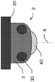
Fig. 3a and 3b each show an exemplary embodiment of a fixedly mounted reality capturing device 2, each sensor unit 3 comprising: a ToF camera unit having three ToF cameras 30, and an imaging unit having one or more cameras 40, 42. The device 2 is attached to a base 20, which may be fixedly mounted on a moving or immobile object (e.g., a vehicle or a roof or wall). The base may be mounted such that the first axis 8 is vertical or horizontal or at any angle between vertical and horizontal.
The sensor unit 3 of the mounted reality capturing device 2 of fig. 3a comprises: a ToF camera unit having three ToF cameras 30 (only two of which are visible in this view), and a single fisheye camera comprising a fisheye lens 40 for capturing image data within 360 ° around the first axis 8 of the device. The optical axis of the fisheye camera may coincide or be parallel with the first axis 8.
The sensor unit 3 of the mounted reality capturing device 2 of fig. 3b comprises the same ToF camera unit as in fig. 2 a. Instead of fisheye cameras, the imaging unit in this embodiment comprises three cameras 42 (only one camera is visible in this view) arranged between the three ToF cameras 30. The three cameras are arranged such that they capture image data within 360 ° around the first axis 8.
Fig. 4a and 4b each show the sensor unit 3 of the reality capturing apparatus of fig. 2a, 2b and 3a, 3 b. The cameras on the back and inside are visible here with dashed lines. In both embodiments, the sensor unit 3 comprises three ToF cameras 30, said three ToF cameras 30 being arranged at equal distances around the housing of the sensor unit 3 to cover a hemispherical field of view.
Inside the sensor unit 3 of fig. 4a, a high definition 2D camera 44 is oriented towards the fisheye lens 40 to capture images at high resolution in a hemispherical field of view. On the outer surface of the sensor unit 3 of fig. 4b, three high definition 2D cameras 42 are positioned between the ToF cameras 30 to cover the hemispherical field of view.
Fig. 5a and 5c illustrate an exemplary embodiment of the sensor unit 3 of fig. 4a in more detail.
Fig. 5a shows a fisheye lens 40 on top of unit 30, configured to enable camera 44 to capture images with a 360 ° × 190 ° field of view.
In this embodiment, each of the three ToF cameras 30 is surrounded by three infrared laser emitters 35, wherein the ToF camera is configured to receive reflections of light pulses emitted by the infrared laser emitters 35 and to measure distances from the reflective surface using known time-of-flight principles.
These laser emitters 35 may be passive emitters, including for example fiber couplings, diffraction gratings or fiber-splitting, connected to a central laser source of the device (optionally amplified by, for example, erbium-doped fiber amplifiers). Alternatively, the laser emitters 35 may be active emitters (e.g., laser diodes or Vertical Cavity Surface Emitting Laser (VCSEL) arrays), which may be disposed on the same printed circuit board as the corresponding ToF cameras 30. In addition, a lens may be placed in front of the VCSEL to collimate the emitted laser beam.
In the example shown, the infrared laser emitter 35 (together with the ToF camera 30) is positioned in a section of the housing of the sensor unit 3 that is transparent to infrared light (IR-transparent section 50). This allows hiding the sensitive laser source inside the housing and emitting the light pulses through the IR transparent section 50 onto the surface of the environment.
A range image (range image) captured by the ToF camera can be used for the ToF-based SLAM. To reduce noise in the range image and enhance the accuracy and/or distance range of the SLAM, some or all of the emitters 35 may be configured to project a constant light pattern into the ambient environment such that only a subset of the pixels of the ToF sensor receive range information from the ambient environment of reflections of light emitted by these emitters 35. ToF-based SLAM may optionally be supported by visual SLAM using a 2D camera.
In one embodiment, some or all of emitters 35 may be configured to project a light pattern, for example by projecting light through a diffractive or refractive grating or grid, while other emitters 35 are configured to emit light without the pattern such that the reflections fully illuminate the ToF sensor. If the emitters 35 emit light sequentially, a patterned, incomplete but accurate range image can be used to enhance the results of a complete but noisy range image.
Additionally or alternatively, the ToF camera may be configured to capture intensity images. The intensity images include brightness information of the surrounding environment and may be used to perform a visual SLAM based on the intensity images as the device moves through the surrounding environment. To generate an intensity image, the emitter may emit scattered light rather than a projected pattern. Since the transmitter 35 emits infrared light, the visual SLAM is not visible to the user.
Fig. 5b illustrates an exemplary arrangement of cameras relative to each other, which allows for hemispherical fields of view of three ToF cameras 30. The optical axis 84 of the camera 44 capturing the image through the fisheye lens 40 coincides with the first axis 8.
The number and size of the gaps in the combined field of view of the sensor array of ToF camera 30 should be as small as possible. Some clearance is acceptable if the device is moving during the measurement and moves through the surrounding environment. However, in a hemispherical field of view, the gap should still not exceed 25% in total, preferably less than 10%. Furthermore, the sensor arrays should be arranged such that each sensor array receives only reflections of those light pulses that have been emitted by the laser emitter of the same ToF camera 30, and does not receive reflections of other light pulses. Thus, the sensor arrays of the ToF camera 30 should be arranged with as little overlap as possible.
To reduce both overlap and gaps, three ToF cameras 30 are arranged equidistant from each other, i.e. at an angle of 120 ° to each other, around the housing of the sensor unit 3. Furthermore, toF cameras 30 are oriented such that their optical axes 83 are at an angle of about 55 ° to first axis 8.
Preferably, each ToF camera has a rectangular sensor array to cover a rectangular field of view. The ToF cameras may be arranged vertically (i.e. the longitudinal axis of the array is orthogonal to the first axis 8) or vertically (i.e. rotated 90 ° about the optical axis 83 of the respective camera).
In order to cover the top of the hemisphere with a ToF camera field of view with as little and small gaps as possible (or even without any gaps at all), the ToF cameras are preferably arranged such that the rectangular field of view of each of the ToF cameras 30 is rotated about 35 ° about the optical axis 83 of the respective camera, i.e. such that the longitudinal axis of the array is rotated about 35 ° relative to a second axis orthogonal to the first axis 8. The exact amount of best results may vary between 10 ° and 80 ° and depends inter alia on the aspect ratio of the rectangular array and the number and exact position of the individual cameras on the sensor unit 3.
A suitable ToF camera 30 that may be used with such an apparatus may have, for example, a rectangular ToF sensor array with a resolution of 640 x 480 pixels, a pixel size of 5 μm, and a diagonal of 4.0mm (e.g., 3.2mm x 2.4 mm). An exemplary suitable RGB sensor for fisheye camera 44 may have a resolution of 5496 x 3694 pixels, a pixel size of 2.4 μm, and a diagonal of 15.86mm (e.g., 13.19mm x 8.86 mm).
Fig. 5c shows a sensor array 33 of ToF cameras arranged obliquely to the above-mentioned second axis 9. The second axis 9 is orthogonal to the first axis 8. The emission axis (emission axis) 83 of the sensor array 33 is directed towards the observer. The sensor array 33 is rectangular with an aspect ratio of about 4. A longitudinal axis 93 parallel to two of the sides of the rectangular sensor array 33 is orthogonal to the emission axis 83 and is inclined at an angle a (e.g., between 10 ° and 45 °, such as about 20 ° or about 35 °) relative to the second axis 9.
Fig. 5d shows a sensor array 33 of ToF cameras arranged obliquely to the first axis 8 mentioned above. The emission axis 83 is orthogonal to the rectangular sensor array 33 and is inclined at an angle β (e.g., greater than 30 °, particularly between 45 ° and 65 °, such as about 55 °) relative to the first axis 8.
Fig. 6 illustrates internal components of an exemplary reality capturing device according to the present invention. The sensor unit 3 is mounted to a second part which may be embodied as a handle part of the mobile reality capturing apparatus 1 as described with reference to fig. 2a and 2b, or as a base part 20 of the fixedly mounted reality capturing apparatus 2 as described with reference to fig. 3a and 3 b. The sensor unit 3 comprises a fisheye camera device with a camera 44 and a super wide angle "fisheye lens" for capturing image data with (at least) a hemispherical field of view. The sensor unit 3 further comprises a plurality of ToF cameras 30, each comprising a ToF sensor array and one or more laser emitters 35 (e.g. laser diodes). In the simplified example shown, there are two ToF cameras 30, however, three or more ToF cameras 30 may also be used in order to cover a 360 ° field of view.
The second part, i.e. the handle part or the base part, comprises an energy supply unit 13, which energy supply unit 13 is used to supply electrical energy to the other components of the second part and to the sensor unit 3. It may include a rechargeable battery or one or more receptacles for receiving one or more replaceable batteries. Alternatively or additionally, the energy providing unit 13 may comprise means for connecting to an external power source, e.g. a grid connection via a cable, plug and socket. If the device is a mobile reality capturing device, the rechargeable battery may be charged by an external power source, or the device may operate when connected to the power grid through a cable.
Especially if the apparatus is a mobile reality capturing apparatus, the second part (e.g. the handle part) may further comprise a positioning unit 14 configured to continuously determine the position of the apparatus, e.g. for determining the trajectory of the mobile reality capturing apparatus during the measurement procedure. For example, the positioning unit 14 includes an Inertial Measurement Unit (IMU) and a GNSS receiver. The location unit 14 may also include other sensors, such as a compass and a barometer, or be configured to infer the location of the device from wireless communication signals, such as a WLAN. The positioning unit 14 may also be configured to perform a simultaneous positioning and mapping (SLAM) function using the data of the sensor unit 3, i.e. the image data generated by the camera 44. Optionally, the 3D data generated by ToF camera 30 and/or data from the IMU may also be used to improve SLAM functionality.
The second part also comprises a communication unit 15, which communication unit 15 is used to provide the data generated in the sensor unit 3 to an external computer (e.g. a hand-held device of an operator) or to a server computer or to the cloud. The communication unit 15 may be configured as a wireless communication unit, for example, by means of WLAN, bluetooth or mobile radio to provide data. Alternatively, the communication unit 15 may be configured as a tethered communication unit. In the case of a fixedly mounted device, the data can then be provided by means of a LAN cable. If the device is mobile, the communication unit 15 may comprise a USB or similar socket for connecting the mobile device. The communication unit 15 may be configured to provide the data continuously, e.g. by streaming the data in real time. Alternatively, the data may be uploaded to the external device after the measurement process has been completed, for example when the external device is connected by means of a cable or bluetooth. The communication unit 15 may comprise data storage means for storing the captured data until it is provided. Processing or post-processing of the uploaded or streamed data may be performed at an external computer or in the cloud, as desired. Alternatively or additionally, the apparatus may comprise a processor 16 configured to process data. The processor 16 may also be configured to pre-process data, wherein the communication unit 15 is configured to upload and/or stream the pre-processed data to allow post-processing of the pre-processed data at the computer or in the cloud.
Although the components 13 to 16 are here depicted as part of the second part, some or all of these units may of course also be integrated into the sensor unit 3.
Although the invention has been exemplified above, in part with respect to some preferred embodiments, it must be understood that many modifications and combinations of different features of these embodiments may be made. All of these modifications fall within the scope of the appended claims.
Claims (15)
1. A reality capturing apparatus (1, 2) configured to perform a measurement process for generating a digital representation of an environment, wherein the reality capturing apparatus comprises a body defining a first axis (8), the reality capturing apparatus comprising an imaging unit with one or more 2D cameras (42, 44) configured to provide two-dimensional image data of the environment,
it is characterized in that the preparation method is characterized in that,
the reality capturing device (1, 2) comprises a ToF camera device configured to capture three-dimensional point cloud data of the environment and comprising at least two time-of-flight cameras (30), wherein,
each time-of-flight camera (30) comprising a sensor array (33) and one or more laser emitters (35),
the sensor array (33) of each of the time-of-flight cameras (30) has an optical axis (83) and is configured to receive reflections of light pulses emitted by the one or more laser emitters (35) of the respective time-of-flight camera (30), and
the at least two time-of-flight cameras (30) are arranged around the first axis (8) such that each sensor array has one or two other sensor arrays as proximity sensor arrays, wherein the angle around the first axis (8) between the optical axis (83) of a sensor array and the optical axis (83) of one of its proximity sensor arrays is not more than Wherein n is the number of time-of-flight cameras (30) arranged around the first axis (8).
2. The reality capturing apparatus (1, 2) of claim 1, the ToF camera apparatus comprising at least three time-of-flight cameras (30) around the first axis (8) such that each sensor array (33) has two other sensor arrays (33) as proximity sensor arrays, wherein an angle around the first axis (8) between the optical axis (83) of a sensor array (33) and an optical axis (83) of one of the proximity sensor arrays of that sensor array (33) is not more than 140 °.
3. Reality capturing apparatus (1, 2) according to claim 1 or 2,
each of the time-of-flight cameras (30) has a rectangular sensor array (33) having a longitudinal axis (93) parallel to both sides of the sensor array (33) and orthogonal to the respective optical axis (83), wherein each sensor array (33) is arranged such that the longitudinal axis (93) of that sensor array (33) is inclined with respect to a second axis (9) orthogonal to the first axis (8) such that the angle a between the longitudinal axis (93) and the second axis (9) is between 10 ° and 45 °, in particular about 35 °; and/or
The sensor array (33) is arranged inclined with respect to the first axis (8) such that an angle beta between the first axis and the optical axis (83) of each time-of-flight camera is between 45 DEG and 65 DEG, in particular about 55 DEG,
in particular, the aspect ratio of each sensor array (33) is 4.
4. Reality capturing apparatus (1, 2) according to any of the preceding claims,
each sensor array has a resolution of at least 0.3 megapixels, particularly wherein each sensor array has a resolution of at least 640 x 480 pixels;
the sensor arrays are arranged and configured for collectively covering at least 75%, in particular at least 90%, of a hemispherical field of view; and/or
The laser transmitters (35) comprise laser diodes provided on a printed circuit board of the respective time-of-flight camera (30) and/or configured to emit infrared light.
5. Reality capturing device (1, 2) according to any of the preceding claims, wherein two or more 2D cameras (42), in particular at least three 2D cameras (42), are arranged around the first axis (8), wherein,
the 2D cameras (42) are arranged and configured to collectively cover at least a field of view covered by the sensor array;
the 2D cameras (42) are arranged and configured to collectively cover at least 75%, in particular at least 90%, of a hemispherical field of view; and/or
At least a subset of the 2D cameras (42) are ultra high definition cameras, particularly wherein each of the ultra high definition cameras is configured to provide an image having at least 20 megapixels.
6. Reality capturing device (1, 2) according to any one of the preceding claims, wherein the imaging unit comprises a fish-eye camera device having a high resolution 2D camera (44) and a fish-eye lens (40), the high resolution 2D camera (44) and the fish-eye lens (40) of the fish-eye camera device being arranged and configured to capture image data covering a 360 ° field of view around the first axis and at least a 160 ° field of view around a second axis (9) orthogonal to the first axis (8), in particular wherein,
the high resolution 2D camera (44) and the fisheye lens (42) of the fisheye camera device being arranged and configured to capture image data covering a 360 ° field of view around the first axis and at least a 190 ° field of view around the second axis (9),
the high resolution 2D camera (44) has a first optical axis (84) parallel to the first axis (8) or coincident with the first axis (8), and/or
The high resolution 2D camera (44) is an ultra high definition camera, in particular an ultra high definition camera configured to provide images having at least 20 megapixels.
7. Reality capturing device (1, 2) according to any one of the preceding claims, wherein the time-of-flight camera (30) and the at least one 2D camera (42, 44) are integrated into the body, wherein the body has a housing with a side surface defining the first axis (8), in particular wherein,
the side surfaces are arranged circumferentially around the first axis (8), and/or
The housing comprises a permeable area (50) permeable to infrared radiation, and the laser emitter (35) is integrated into the housing and configured to emit an infrared laser beam through the permeable area (50), in particular wherein the time-of-flight camera (30) is integrated into the housing at the permeable area (50).
8. Reality capturing device according to any one of the preceding claims, wherein the reality capturing device is a mobile reality capturing device (1) configured to be carried and moved by a moving carrier, in particular a person, a robot, a vehicle or an aircraft, and to be moved during the measurement process, the mobile reality capturing device (1) comprising a positioning unit (14) configured to continuously determine the pose of the mobile reality capturing device (1) and to generate positioning data, in particular wherein,
the positioning unit (14) comprises an inertial measurement unit and/or is configured to determine a trajectory of the mobile reality capturing device (1);
-the mobile reality capturing device (1) is designed to be oriented during the measurement process so that the first axis (8) is vertical; and/or
The mobile reality capturing device (1) comprises a handle portion (10) and is configured to be carried by a person.
9. Reality capturing apparatus (1) according to claim 8, the reality capturing apparatus being configured to: -performing the measurement procedure while the reality capturing device (1) is moving along a path through the environment, during which measurement procedure,
continuously capturing three-dimensional point cloud data of the environment with the time-of-flight camera (30),
continuously capturing two-dimensional image data of the environment with the one or more 2D cameras (42, 44),
configuring the positioning unit (14) to continuously generate positioning data as the real capture device (1) moves along the path and to track a pose of the real capture device (1) based on the positioning data, in particular to track the pose of the real capture device (1) in 6 degrees of freedom, and
configuring the reality capturing apparatus (1) to link the captured point cloud data and image data to the pose at the time the point cloud data and the image data were captured,
in particular wherein the time-of-flight camera (30) and the one or more 2D cameras (42, 44) are each configured to capture and provide the three-dimensional point cloud data and the two-dimensional image data at a rate of at least 5 operations per second, in particular at a rate of at least 25 operations per second.
10. Reality capturing device (1) according to claim 8 or 9, wherein the positioning unit (14) is configured to perform:
a ToF-SLAM function using the three-dimensional point cloud data, in particular also using two-dimensional image data of the imaging unit and/or positioning data of the positioning unit (14), for simultaneous positioning and mapping; and/or
A pose and trajectory determination function for continuously determining a pose and trajectory of the reality capturing apparatus (1) based on two-dimensional image data of the imaging unit and/or based on three-dimensional point cloud data, in particular also based on positioning data of the positioning unit (14).
11. Reality capturing apparatus (1) according to any of claims 8 to 10,
at least a subset of the laser emitters (35) is configured to emit light pulses in a pattern, thereby generating a reflection pattern of the light pulses, and
the ToF camera device is configured to capture three-dimensional point cloud data using the reflection pattern,
in particular wherein the presence of a catalyst is preferred,
the subset of the laser emitters (35) comprises an optical lens, grating or grid to generate the pattern, and/or
A localization unit (14) of the reality capturing device is configured to use the three-dimensional point cloud data of the reflection pattern to perform a ToF SLAM function for simultaneous localization and mapping.
12. Reality capturing apparatus (1) according to any one of claims 8 to 11,
the laser emitter (35) is configured to emit diffuse infrared illumination,
the sensor array of each of the time-of-flight cameras (30) is configured to receive reflections of the scattered infrared illumination emitted by the one or more laser emitters (35) of the respective time-of-flight camera (30),
the time-of-flight camera (30) is configured to generate an intensity image based on the received reflections of the scattered infrared illumination, an
The localization unit (14) is configured to perform a visual-SLAM and/or ToF-SLAM function which uses the intensity images received from the time-of-flight camera (30), in particular also using two-dimensional image data of the imaging unit and/or localization data of the localization unit (14), for simultaneous localization and mapping.
13. Reality capturing device (1) according to any one of claims 8 to 12, wherein the reality capturing device comprises a handle portion (10), the reality capturing device and the handle portion (10) being designed such that the reality capturing device can be held by a user during the measurement procedure, wherein,
the reality capturing device and the handle portion (10) are designed such that the first axis (8) of the reality capturing device is kept inclined away from the user, in particular at an angle of less than 20 ° with respect to the vertical; and/or
The time-of-flight camera (30) is arranged about the first axis (8) such that the one or more laser emitters (35) do not emit light pulses into a direction of the user holding the reality capturing device, the direction being defined by the position of the handle portion (10) relative to the first axis (8).
14. Reality capturing apparatus (1, 2) according to any of the preceding claims, further comprising:
a processor (16) configured to process or pre-process the point cloud data and/or the image data; and/or
A communication unit (15) configured to upload and/or stream point cloud data and/or image data into a computer or a public or enterprise cloud, in particular wherein the communication unit (15) is a wireless communication unit configured to upload and/or stream the point cloud data and/or image data via WLAN, bluetooth or mobile radio,
in particular wherein the processor (16) is configured to pre-process point cloud data and/or image data and the wireless communication unit (15) is configured to upload and/or stream the pre-processed point cloud data and/or image data to allow post-processing of the pre-processed data at the computer or cloud.
15. A method of spatially mapping an environment using a mobile reality capturing device, in particular using a mobile reality capturing device (1) according to any of claims 8 to 14, the method comprising the steps of: continuously capturing three-dimensional point cloud data and two-dimensional image data of the environment while moving along a path through the environment, wherein,
the two-dimensional image data is captured by one or more 2D cameras (42, 44) arranged on the reality capture device and configured to collectively cover at least 75% of a hemispherical field of view;
the three-dimensional point cloud data of the environment is captured simultaneously with a plurality of time-of-flight cameras (30), each time-of-flight camera (30) comprising a sensor array and one or more laser emitters (35), the sensor array receiving reflections of light pulses emitted by the one or more laser emitters (35) of the respective time-of-flight camera (30), the sensor array being arranged on the reality capture device and configured to collectively cover at least 75% of a hemispherical field of view; and
continuously generating positioning data while moving along the path, tracking a location based on the positioning data, and linking captured point cloud data and image data to the location at which the point cloud data and the image data were captured.
Applications Claiming Priority (2)
| Application Number | Priority Date | Filing Date | Title |
|---|---|---|---|
| EP21176387.5 | 2021-05-27 | ||
| EP21176387.5A EP4095561A1 (en) | 2021-05-27 | 2021-05-27 | Reality capture device |
Publications (1)
| Publication Number | Publication Date |
|---|---|
| CN115407363A true CN115407363A (en) | 2022-11-29 |
Family
ID=76217649
Family Applications (1)
| Application Number | Title | Priority Date | Filing Date |
|---|---|---|---|
| CN202210549435.6A Pending CN115407363A (en) | 2021-05-27 | 2022-05-20 | Reality capturing device |
Country Status (3)
| Country | Link |
|---|---|
| US (1) | US20220414915A1 (en) |
| EP (1) | EP4095561A1 (en) |
| CN (1) | CN115407363A (en) |
Families Citing this family (1)
| Publication number | Priority date | Publication date | Assignee | Title |
|---|---|---|---|---|
| JP2023019059A (en) * | 2021-07-28 | 2023-02-09 | 株式会社リコー | Imaging apparatus and imaging system |
Family Cites Families (6)
| Publication number | Priority date | Publication date | Assignee | Title |
|---|---|---|---|---|
| WO2014106296A1 (en) * | 2013-01-07 | 2014-07-10 | Tamaggo Inc. | Panoramic camera |
| WO2018140656A1 (en) * | 2017-01-26 | 2018-08-02 | Matterport, Inc. | Capturing and aligning panoramic image and depth data |
| DE102017107903A1 (en) * | 2017-04-12 | 2018-10-18 | Sick Ag | 3D light-time camera and method for acquiring three-dimensional image data |
| EP3671261A1 (en) | 2018-12-21 | 2020-06-24 | Leica Geosystems AG | 3d surveillance system comprising lidar and multispectral imaging for object classification |
| KR20230028792A (en) * | 2020-06-22 | 2023-03-02 | 인터디지탈 패튼 홀딩스, 인크 | Adaptive streaming of geometry-based point clouds |
| US20220291386A1 (en) * | 2021-03-10 | 2022-09-15 | Neophotonics Corporation | Lidar with 4d object classification, solid state optical scanning arrays, and effective pixel designs |
-
2021
- 2021-05-27 EP EP21176387.5A patent/EP4095561A1/en active Pending
-
2022
- 2022-05-20 CN CN202210549435.6A patent/CN115407363A/en active Pending
- 2022-05-27 US US17/827,527 patent/US20220414915A1/en active Pending
Also Published As
| Publication number | Publication date |
|---|---|
| US20220414915A1 (en) | 2022-12-29 |
| EP4095561A1 (en) | 2022-11-30 |
Similar Documents
| Publication | Publication Date | Title |
|---|---|---|
| US10481237B2 (en) | Method and apparatus for using gestures to control a measurement device | |
| US9417317B2 (en) | Three-dimensional measurement device having three-dimensional overview camera | |
| US10175360B2 (en) | Mobile three-dimensional measuring instrument | |
| US11879997B2 (en) | System for surface analysis and method thereof | |
| US20190079522A1 (en) | Unmanned aerial vehicle having a projector and being tracked by a laser tracker | |
| US9612331B2 (en) | Laser tracker with functionality for graphical target preparation | |
| CN107991681A (en) | Laser radar and its scan method based on diffraction optics | |
| US20220257001A1 (en) | Frame for at least one scanning device and spatial detection device with at least one scanning device | |
| CN207408590U (en) | A kind of laser radar based on two-dimentional DOE elements | |
| US10893190B2 (en) | Tracking image collection for digital capture of environments, and associated systems and methods | |
| GB2547763A (en) | Method for optically scanning and measuring an environment using a 3D measurement device and near field communication | |
| US20220414915A1 (en) | Reality capture device | |
| US20220137225A1 (en) | Three dimensional measurement device having a camera with a fisheye lens | |
| US10591603B2 (en) | Retroreflector acquisition in a coordinate measuring device | |
| US11009887B2 (en) | Systems and methods for remote visual inspection of a closed space | |
| GB2547761A (en) | A method for optically scanning and measuring an environment using a 3D measurement device and near field communication | |
| EP4258023A1 (en) | Capturing three-dimensional representation of surroundings using mobile device | |
| CN219301541U (en) | Three-dimensional measurement and modeling equipment | |
| EP4024339A1 (en) | Automatic registration of multiple measurement devices |
Legal Events
| Date | Code | Title | Description |
|---|---|---|---|
| PB01 | Publication | ||
| PB01 | Publication | ||
| SE01 | Entry into force of request for substantive examination | ||
| SE01 | Entry into force of request for substantive examination |