CN115405718A - Track ball valve convenient to change filler - Google Patents
Track ball valve convenient to change filler Download PDFInfo
- Publication number
- CN115405718A CN115405718A CN202211042327.6A CN202211042327A CN115405718A CN 115405718 A CN115405718 A CN 115405718A CN 202211042327 A CN202211042327 A CN 202211042327A CN 115405718 A CN115405718 A CN 115405718A
- Authority
- CN
- China
- Prior art keywords
- valve
- sealing
- groove
- ring
- packing
- Prior art date
- Legal status (The legal status is an assumption and is not a legal conclusion. Google has not performed a legal analysis and makes no representation as to the accuracy of the status listed.)
- Granted
Links
- 239000000945 filler Substances 0.000 title claims abstract description 37
- 230000008859 change Effects 0.000 title description 10
- 238000007789 sealing Methods 0.000 claims abstract description 126
- 238000012856 packing Methods 0.000 claims abstract description 46
- 210000004907 gland Anatomy 0.000 claims abstract description 17
- 230000007246 mechanism Effects 0.000 claims abstract description 9
- 238000005096 rolling process Methods 0.000 claims description 22
- 238000003825 pressing Methods 0.000 claims description 9
- 238000000034 method Methods 0.000 claims description 6
- 230000006835 compression Effects 0.000 claims description 3
- 238000007906 compression Methods 0.000 claims description 3
- 230000000149 penetrating effect Effects 0.000 claims description 2
- 238000012423 maintenance Methods 0.000 abstract description 13
- 230000008901 benefit Effects 0.000 abstract description 8
- 230000000694 effects Effects 0.000 description 5
- 238000009434 installation Methods 0.000 description 4
- VNWKTOKETHGBQD-UHFFFAOYSA-N methane Chemical compound C VNWKTOKETHGBQD-UHFFFAOYSA-N 0.000 description 4
- 230000001174 ascending effect Effects 0.000 description 3
- 230000008569 process Effects 0.000 description 3
- 230000009471 action Effects 0.000 description 2
- 238000001125 extrusion Methods 0.000 description 2
- 239000002808 molecular sieve Substances 0.000 description 2
- 239000003345 natural gas Substances 0.000 description 2
- 230000001737 promoting effect Effects 0.000 description 2
- 238000000926 separation method Methods 0.000 description 2
- URGAHOPLAPQHLN-UHFFFAOYSA-N sodium aluminosilicate Chemical compound [Na+].[Al+3].[O-][Si]([O-])=O.[O-][Si]([O-])=O URGAHOPLAPQHLN-UHFFFAOYSA-N 0.000 description 2
- VGGSQFUCUMXWEO-UHFFFAOYSA-N Ethene Chemical compound C=C VGGSQFUCUMXWEO-UHFFFAOYSA-N 0.000 description 1
- 239000005977 Ethylene Substances 0.000 description 1
- 230000003247 decreasing effect Effects 0.000 description 1
- 230000018044 dehydration Effects 0.000 description 1
- 238000006297 dehydration reaction Methods 0.000 description 1
- 238000005984 hydrogenation reaction Methods 0.000 description 1
- 230000007774 longterm Effects 0.000 description 1
- 239000007769 metal material Substances 0.000 description 1
- 230000002035 prolonged effect Effects 0.000 description 1
- 239000000126 substance Substances 0.000 description 1
Images


Classifications
-
- F—MECHANICAL ENGINEERING; LIGHTING; HEATING; WEAPONS; BLASTING
- F16—ENGINEERING ELEMENTS AND UNITS; GENERAL MEASURES FOR PRODUCING AND MAINTAINING EFFECTIVE FUNCTIONING OF MACHINES OR INSTALLATIONS; THERMAL INSULATION IN GENERAL
- F16K—VALVES; TAPS; COCKS; ACTUATING-FLOATS; DEVICES FOR VENTING OR AERATING
- F16K5/00—Plug valves; Taps or cocks comprising only cut-off apparatus having at least one of the sealing faces shaped as a more or less complete surface of a solid of revolution, the opening and closing movement being predominantly rotary
- F16K5/06—Plug valves; Taps or cocks comprising only cut-off apparatus having at least one of the sealing faces shaped as a more or less complete surface of a solid of revolution, the opening and closing movement being predominantly rotary with plugs having spherical surfaces; Packings therefor
-
- F—MECHANICAL ENGINEERING; LIGHTING; HEATING; WEAPONS; BLASTING
- F16—ENGINEERING ELEMENTS AND UNITS; GENERAL MEASURES FOR PRODUCING AND MAINTAINING EFFECTIVE FUNCTIONING OF MACHINES OR INSTALLATIONS; THERMAL INSULATION IN GENERAL
- F16K—VALVES; TAPS; COCKS; ACTUATING-FLOATS; DEVICES FOR VENTING OR AERATING
- F16K27/00—Construction of housing; Use of materials therefor
- F16K27/06—Construction of housing; Use of materials therefor of taps or cocks
- F16K27/067—Construction of housing; Use of materials therefor of taps or cocks with spherical plugs
-
- F—MECHANICAL ENGINEERING; LIGHTING; HEATING; WEAPONS; BLASTING
- F16—ENGINEERING ELEMENTS AND UNITS; GENERAL MEASURES FOR PRODUCING AND MAINTAINING EFFECTIVE FUNCTIONING OF MACHINES OR INSTALLATIONS; THERMAL INSULATION IN GENERAL
- F16K—VALVES; TAPS; COCKS; ACTUATING-FLOATS; DEVICES FOR VENTING OR AERATING
- F16K41/00—Spindle sealings
- F16K41/02—Spindle sealings with stuffing-box ; Sealing rings
- F16K41/04—Spindle sealings with stuffing-box ; Sealing rings with at least one ring of rubber or like material between spindle and housing
- F16K41/043—Spindle sealings with stuffing-box ; Sealing rings with at least one ring of rubber or like material between spindle and housing for spindles which only rotate, i.e. non-rising spindles
- F16K41/046—Spindle sealings with stuffing-box ; Sealing rings with at least one ring of rubber or like material between spindle and housing for spindles which only rotate, i.e. non-rising spindles for rotating valves
-
- F—MECHANICAL ENGINEERING; LIGHTING; HEATING; WEAPONS; BLASTING
- F16—ENGINEERING ELEMENTS AND UNITS; GENERAL MEASURES FOR PRODUCING AND MAINTAINING EFFECTIVE FUNCTIONING OF MACHINES OR INSTALLATIONS; THERMAL INSULATION IN GENERAL
- F16K—VALVES; TAPS; COCKS; ACTUATING-FLOATS; DEVICES FOR VENTING OR AERATING
- F16K5/00—Plug valves; Taps or cocks comprising only cut-off apparatus having at least one of the sealing faces shaped as a more or less complete surface of a solid of revolution, the opening and closing movement being predominantly rotary
- F16K5/06—Plug valves; Taps or cocks comprising only cut-off apparatus having at least one of the sealing faces shaped as a more or less complete surface of a solid of revolution, the opening and closing movement being predominantly rotary with plugs having spherical surfaces; Packings therefor
- F16K5/0663—Packings
- F16K5/0689—Packings between housing and plug
-
- F—MECHANICAL ENGINEERING; LIGHTING; HEATING; WEAPONS; BLASTING
- F16—ENGINEERING ELEMENTS AND UNITS; GENERAL MEASURES FOR PRODUCING AND MAINTAINING EFFECTIVE FUNCTIONING OF MACHINES OR INSTALLATIONS; THERMAL INSULATION IN GENERAL
- F16K—VALVES; TAPS; COCKS; ACTUATING-FLOATS; DEVICES FOR VENTING OR AERATING
- F16K5/00—Plug valves; Taps or cocks comprising only cut-off apparatus having at least one of the sealing faces shaped as a more or less complete surface of a solid of revolution, the opening and closing movement being predominantly rotary
- F16K5/06—Plug valves; Taps or cocks comprising only cut-off apparatus having at least one of the sealing faces shaped as a more or less complete surface of a solid of revolution, the opening and closing movement being predominantly rotary with plugs having spherical surfaces; Packings therefor
- F16K5/0663—Packings
- F16K5/0694—Spindle sealings
-
- F—MECHANICAL ENGINEERING; LIGHTING; HEATING; WEAPONS; BLASTING
- F16—ENGINEERING ELEMENTS AND UNITS; GENERAL MEASURES FOR PRODUCING AND MAINTAINING EFFECTIVE FUNCTIONING OF MACHINES OR INSTALLATIONS; THERMAL INSULATION IN GENERAL
- F16K—VALVES; TAPS; COCKS; ACTUATING-FLOATS; DEVICES FOR VENTING OR AERATING
- F16K5/00—Plug valves; Taps or cocks comprising only cut-off apparatus having at least one of the sealing faces shaped as a more or less complete surface of a solid of revolution, the opening and closing movement being predominantly rotary
- F16K5/08—Details
- F16K5/14—Special arrangements for separating the sealing faces or for pressing them together
- F16K5/20—Special arrangements for separating the sealing faces or for pressing them together for plugs with spherical surfaces
Landscapes
- Engineering & Computer Science (AREA)
- General Engineering & Computer Science (AREA)
- Mechanical Engineering (AREA)
- Taps Or Cocks (AREA)
Abstract
The invention discloses a track ball valve convenient for replacing a filler, which comprises a valve body, a valve cover, a ball body and a valve rod, wherein the ball body is arranged in an inner cavity of the valve body; the sealing mechanism comprises a packing gland, sealing packing, an upper gasket, a lower gasket, a stress ring and a prying assembly, a sealing cavity is formed in the valve cover, the upper gasket, the sealing packing, the lower gasket and the stress ring are arranged in the sealing cavity, the packing gland is connected with the valve cover through an eyelet bolt, the upper gasket, the sealing packing, the lower gasket and the stress ring are pressed in the sealing cavity by the packing gland, and the prying assembly is installed on the valve rod and matched with the stress ring. The invention is convenient for the operation of replacing the filler in the later maintenance and has the advantages of time saving and labor saving.
Description
Technical Field
The invention relates to the technical field of valves, in particular to a track ball valve convenient for replacing a filler.
Background
The track ball valve is a ball valve with a special structure, and can realize the rotary opening and closing of a valve core, the switch has no friction, and forced sealing can be realized. The method is more and more widely applied to the chemical field, particularly under the working conditions of quick cutting and high and low temperature alternation, such as: the device comprises a natural gas molecular sieve dehydration device, a hydrogenation device, a natural gas metering station, an alternating temperature track ball valve for an inlet and an outlet of a low-temperature cold box of a large-scale ethylene device, a molecular sieve track ball valve and the like.
The working principle of the existing track ball valve is as follows: the valve rod moves up or down under the action of the hand wheel, the guide groove on the valve rod is contacted with the guide pin, and the valve rod performs ninety-degree rotary motion after performing a section of linear motion. During linear motion, the wedge-shaped surface at the lower end of the valve rod pushes the ball body to be close to the valve seat to realize sealing, or the ball body is separated from the valve seat to open the valve; then under the action of the guide groove and the guide pin, the valve rod drives the ball body to rotate 90 degrees. The opening and closing process of the valve is realized through the ascending and descending motion of the valve rod. The maintenance needs to be changed to the packing between valve rod and the valve gap to current track ball valve after long-term the use to guarantee good sealing between the two, however, at the in-process of dismantling the ball valve, can take place the condition that packing and valve gap seal chamber inner wall are cohered together usually, lead to the packing to be difficult to take out, this has brought very big trouble for the operation of packing change.
Disclosure of Invention
The invention aims to provide a track ball valve convenient for replacing a filler, which is convenient for the operation of replacing the filler in the later maintenance and has the advantages of time saving and labor saving.
In order to achieve the purpose, the invention provides the following technical scheme: the track ball valve convenient for replacing the packing comprises a valve body, a valve cover, a ball body and a valve rod, wherein the ball body is arranged in an inner cavity of the valve body, the valve cover is arranged at the upper end of the valve body, the valve rod penetrates through the valve cover, a sealing mechanism which is in sealing fit with the valve rod is arranged on the valve cover, the inner end of the valve rod is in linkage connection with the ball body, an actuator is arranged above the valve cover, the output end of the actuator is in linkage connection with the outer end of the valve rod, and a valve seat is further arranged in the valve body; the sealing mechanism comprises a packing gland, a sealing filler, an upper gasket, a lower gasket, a stress ring and a prying assembly, wherein a sealing cavity coaxial with the valve rod is formed in the valve cover, the upper gasket, the sealing filler, the lower gasket and the stress ring are sequentially arranged in the sealing cavity from outside to inside, the packing gland is connected with the valve cover through an eyelet bolt, the packing gland tightly presses the upper gasket, the sealing filler, the lower gasket and the stress ring in the sealing cavity, and the prying assembly is arranged on the valve rod, matched with the stress ring and used for applying axial force to the stress ring when the sealing filler is replaced.
Through adopting the above technical scheme, when needing to change the packings, only need loosen gland earlier, then pry open the subassembly through the operation and exert ascending axial force to the atress circle, can be with the atress circle and set up the last gasket in atress circle top, the packings, lower gasket is pried, it rises to drive the valve rod through the executor at last, the packings is taken out sealed chamber under the effect of priing open the subassembly, the rethread is demolishd the valve gap and can be taken out the packings and change, the operation is very convenient, it has labour saving and time saving's advantage.
The invention is further arranged in that the prying component comprises a prying block, a first spring, an upper slide block, a plurality of middle slide blocks, a lower slide block, a slide sleeve, a connecting column, a supporting rod, a second spring and a trigger screw sleeve, a pair of axially extending slide cavities are symmetrically arranged on the valve rod, an upper mounting hole communicated with the upper part of the slide cavity and a lower mounting hole communicated with the lower part of the slide cavity are arranged at the side part of the valve rod, the prying block is slidably arranged in the lower mounting hole, at least two first sealing rings which are in sealing fit with the inner wall of the lower mounting hole are axially arranged on the periphery of the prying block, a lower mounting groove is arranged at the position of the valve rod corresponding to the outer end of the lower mounting hole, a limiting block is arranged on the lower mounting groove through a screw, the lower end of the limiting block extends into the lower mounting hole, and a guide channel extending towards the direction of the sealing cavity is formed by the lower end of the limiting block and the lower part of the inner wall of the lower mounting hole, the skid block is provided with a guide part matched with the guide channel, the outer end of the guide part is provided with a first inclined plane used for tilting the stress ring, the stress ring is provided with a first guide inclined plane and a second guide inclined plane matched with the first inclined plane in the direction far away from the first inclined plane, the inclination of the first inclined plane is smaller than that of the first guide inclined plane and larger than that of the second guide inclined plane, the skid block and the limiting block are respectively provided with a first positioning groove and a second positioning groove, the two ends of the first spring are respectively embedded in the first positioning groove and the second positioning groove, the upper sliding block, the plurality of middle sliding blocks and the lower sliding block are sequentially arranged in the sliding cavity from top to bottom, the upper sliding block, the plurality of middle sliding blocks and the lower sliding block are of hollow structures so as to reduce the weight, and the inner end of the skid block is provided with a second inclined plane, be equipped with on the lower slider with second inclined plane matched with third inclined plane, the height of top shoe, a plurality of well slider and lower slider is the same, the height that highly is not less than the top shoe of going up the mounting hole, the sliding sleeve cover is established in the valve rod periphery, and the inboard of sliding sleeve is equipped with first circular slot, the lateral part of top shoe is equipped with the second circular slot, inlay respectively in first circular slot and second circular slot at the both ends of spliced pole to the both ends of spliced pole respectively with first circular slot and second circular slot interference fit, the spring groove has been seted up to the bottom of going up the mounting hole inner wall, the second spring sets up in the spring groove, the lower part of bracing piece slides and sets up in the spring groove and the lower extreme of bracing piece supports in second spring upper end, the upper end of bracing piece is equipped with the arc supporting part that is used for holding the spliced pole, it is used for promoting the sliding sleeve endwise slip to trigger threaded connection to correspond the position of sliding sleeve top on the valve rod.
By adopting the technical scheme, when the sealing filler needs to be replaced, the filler gland is firstly loosened, then the trigger screw sleeve is rotated, the trigger screw sleeve is pressed on the sliding sleeve and enables the sliding sleeve to move downwards, the sliding sleeve drives the upper sliding block, the plurality of middle sliding blocks and the lower sliding block to move downwards, the lower sliding block is matched with the prying block in the descending process to enable the prying block to move outwards, the first inclined plane on the prying block guide part is matched with the first guide inclined plane and the second guide inclined plane on the stress ring, the stress ring is gradually tilted, the stress ring drives the upper gasket, the sealing filler and the lower gasket to move upwards, the valve rod is driven to move upwards by the matching actuator, the effect of pushing the sealing filler out of the sealing cavity can be realized, even if the sealing filler is adhered to the inner wall of the sealing cavity, the sealing filler can be effectively pried away, and the replacement operation of the sealing filler is convenient.
The invention is further provided that the lower end of the trigger screw sleeve is provided with a plurality of groups of rolling contact elements, each rolling contact element comprises a screw rod, a limiting screw sleeve and a ball, a hexagonal operation part is integrally arranged in the middle of the screw rod, the lower end of the trigger screw sleeve is provided with a connecting screw hole for screwing in the upper end of the screw rod, the lower end of the screw rod is provided with a rolling groove, the balls are arranged in the rolling groove, the depth of the rolling groove is smaller than the diameter of the balls and larger than the radius of the balls, the limiting screw sleeve is connected to the lower part of the screw rod in a threaded manner, the lower end of the limiting screw sleeve is provided with a limiting flange extending towards the inner periphery, and the limiting flange abuts against the lower part of the balls to limit the balls in the rolling groove.
Through adopting above-mentioned technical scheme, triggering the swivel nut and adopting rolling contact's mode to exert decurrent effort to the sliding sleeve, can reducing the contact friction between the two, can not only make the operation lighter, can promote the life of spare part moreover.
The invention is further provided that the sliding sleeve comprises a left half ring and a right half ring which are symmetrically arranged, and the left half ring and the right half ring are connected together through screws.
By adopting the technical scheme, the disassembly and assembly operation of the sliding sleeve is greatly facilitated.
The sealing filler comprises a first half ring and a second half ring, two end surfaces of the first half ring, which are attached to the second half ring, are respectively provided with a V-shaped concave part, and two end surfaces of the second half ring, which are attached to the first half ring, are respectively provided with a V-shaped convex part matched with the corresponding V-shaped concave part.
Through adopting above-mentioned technical scheme, not only sealed respond well under the pressurized state, easy dismounting need not separation valve rod and valve gap moreover and can realize the change of sealing filler, greatly reduced the degree of difficulty and the work load that sealing filler changed.
The invention is further arranged in such a way that a threaded groove is formed in the inner wall of the valve body, the valve seat is in threaded connection with the threaded groove, an inner sealing ring which is in sealing fit with the ball body is mounted on the valve seat, a sliding groove is also formed in the inner wall of the valve body along the circumferential direction, a pressing flange which is matched with the sliding groove is arranged on the periphery of the valve seat, an outer sealing ring is clamped between the periphery of the valve seat and the inner wall of the valve body, the inner end of the outer sealing ring abuts against the outer end face of the pressing flange, and the outer end of the outer sealing ring abuts against the end face of the sliding groove.
Through adopting above-mentioned technical scheme, the disk seat passes through threaded connection's mode and installs in the valve body, the dismouting is very convenient, do benefit to the maintenance operation in equipment and the later stage in earlier stage, in order to guarantee the normal use of ball valve, simultaneously, the pressing flange of disk seat compresses tightly the outer seal ring in the inner of the spout of valve body inner wall, the disk seat is screwed more tightly, the outer seal ring just is big more towards the deformation of two directions in inner periphery and periphery, realize effective sealing between disk seat and the valve body inner wall from this, prevent the emergence of leaking.
The invention is further provided that an annular mounting groove is arranged on the valve seat along the circumferential direction, and the inner sealing ring is partially embedded in the annular mounting groove.
Through adopting above-mentioned technical scheme, realized the removable operation of interior sealing washer, practiced thrift the maintenance cost.
The invention is further provided that the inner end and the outer end of the outer sealing ring are both in a tapered shape with gradually reduced width.
By adopting the technical scheme, the contact area of the inner periphery of the outer sealing ring and the outer periphery of the valve seat and the cross-sectional area of the outer periphery of the outer sealing ring and the inner wall of the valve body are reduced, so that the extrusion stress of the outer periphery of the valve seat and the inner wall of the valve body when the outer sealing ring is deformed under pressure is improved, and the sealing performance between the outer periphery of the valve seat and the inner wall of the valve body is further improved.
The invention is further arranged in that a gasket is clamped between the compression flange and the outer sealing ring.
Through adopting above-mentioned technical scheme, the packing ring can play the effect of protection external seal circle and disk seat.
The invention is further set that a support ring is arranged on the inner wall of the valve body through a locking screw, a sealing groove is arranged on one end face, attached to the inner wall of the valve body, of the support ring along the circumferential direction, an O-shaped ring which is used for forming sealing fit with the inner wall of the valve body is embedded in the sealing groove, and the threaded groove and the sliding groove are both formed in the support ring.
Through adopting above-mentioned technical scheme, the lock ring is removable, avoids the thread groove directly to set up and leads to later stage screw thread to damage the problem that is difficult to maintain on the valve body inner wall, and the screw thread only need when damaging promptly with change the lock ring can, has made things convenient for the maintenance operation, simultaneously greatly reduced the maintenance cost.
The invention is further arranged in that a positioning groove is arranged on the inner wall of the valve body along the circumferential direction, and a positioning flange matched with the positioning groove is arranged on the support ring.
Through adopting above-mentioned technical scheme, can fix a position the lock ring before the lock ring installation, the installation operation of the lock ring of being convenient for.
The invention is further arranged in such a way that the support ring is coaxially provided with a large circular groove and a small circular hole from inside to outside, the inner wall of the valve body is provided with a small screw hole corresponding to the small circular hole, the screw rod part of the locking screw penetrates through the small circular hole and is screwed into the small screw hole, and the screw head of the locking screw is embedded into the large circular groove and is abutted against the inner end surface of the large circular groove.
Through adopting above-mentioned technical scheme, can realize being connected between lock ring and the valve body, and connection structure is simple reliable, and easy dismounting does benefit to the equipment of earlier stage and the maintenance operation in later stage.
Drawings
FIG. 1 is a schematic structural view of the present invention as a whole;
FIG. 2 is a schematic structural view of the sealing mechanism of the present invention;
FIG. 3 is an enlarged view of portion A of FIG. 2;
FIG. 4 is an enlarged schematic view of the portion B in FIG. 2;
FIG. 5 is an enlarged view of the portion C of FIG. 2;
FIG. 6 is a schematic structural view of the sliding sleeve of the present invention;
FIG. 7 is a schematic structural view of a trigger nut according to the present invention;
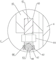
fig. 8 is an enlarged schematic view of a portion D in fig. 1.
In the figure: 1. a valve body; 2. a valve cover; 3. a sphere; 4. a valve stem; 5. an actuator; 6. a valve seat; 7. a thread groove; 8. an inner seal ring; 9. a chute; 10. a compression flange; 11. an outer seal ring; 12. an annular mounting groove; 13. a gasket; 14. locking screws; 15. a support ring; 16. a sealing groove; 17. an O-shaped ring; 18. a positioning groove; 19. a positioning flange; 20. a large circular groove; 21. a small circular hole; 22. a small screw hole; 23. a sealing mechanism; 24. a packing gland; 25. sealing the filler; 26. an upper gasket; 27. a lower gasket; 28. a stress ring; 29. prying the assembly; 30. sealing the cavity; 31. a prying block; 32. a first spring; 33. an upper slide block; 34. a middle slide block; 35. a lower slide block; 36. a sliding sleeve; 37. connecting columns; 38. a support bar; 39. a second spring; 40. triggering the threaded sleeve; 41. a slide chamber; 42. an upper mounting hole; 43. a lower mounting hole; 44. a first seal ring; 45. a lower mounting groove; 46. a limiting block; 47. a guide channel; 48. a guide portion; 49. a first inclined plane; 50. a first guide slope; 51. a second guide slope; 52. a first positioning groove; 53. a second positioning groove; 54. a second inclined plane; 55. a third inclined plane; 56. a first circular groove; 57. a second circular groove; 58. a spring slot; 59. an arc-shaped support part; 60. a rolling contact; 61. a screw; 62. a limiting screw sleeve; 63. a ball bearing; 64. a hexagonal operation portion; 65. a connecting screw hole; 66. a rolling groove; 67. a limiting flange; 68. a left half ring; 69. a right half ring; 70. a first half ring; 71. a second half ring; 72. a V-shaped recess; 73. a V-shaped convex part.
Detailed Description
The technical solutions in the embodiments of the present invention will be clearly and completely described below with reference to the drawings in the embodiments of the present invention, and it is obvious that the described embodiments are only a part of the embodiments of the present invention, and not all of the embodiments. All other embodiments, which can be derived by a person skilled in the art from the embodiments given herein without making any creative effort, shall fall within the protection scope of the present invention.
Example (b): the track ball valve convenient for replacing the packing as shown in the attached figures 1 to 8 comprises a valve body 1, a valve cover 2, a ball body 3 and a valve rod 4, wherein the ball body 3 is arranged in an inner cavity of the valve body 1, the valve cover 2 is arranged at the upper end of the valve body 1, the valve rod 4 is arranged on the valve cover 2 in a penetrating manner, a sealing mechanism 23 which is in sealing fit with the valve rod 4 is arranged on the valve cover 2, the inner end of the valve rod 4 is in linkage connection with the ball body 3, an actuator 5 is arranged above the valve cover 2, the actuator 5 is a pneumatic actuator, and the pneumatic actuator is a conventional mature device, so that the specific structure of the track ball valve is not described in detail herein; the sealing mechanism 23 comprises a packing gland 24, a sealing packing 25, an upper gasket 26, a lower gasket 27, a stress ring 28 and a prying assembly 29, a sealing cavity 30 coaxial with the valve rod 4 is formed in the valve cover 2, the upper gasket 26, the sealing packing 25, the lower gasket 27 and the stress ring 28 are sequentially arranged in the sealing cavity 30 from outside to inside, the packing gland 24 is connected with the valve cover 2 through an eyelet bolt, the packing gland 24 tightly presses the upper gasket 26, the sealing packing 25, the lower gasket 27 and the stress ring 28 in the sealing cavity 30, and the prying assembly 29 is mounted on the valve rod 4 and matched with the stress ring 28 and used for applying axial force to the stress ring 28 when the sealing packing 25 is replaced. When needing to change sealing filler 25, only need loosen gland 24 earlier, then pry open subassembly 29 through the operation and exert ascending axial force to atress circle 28, can be with atress circle 28 and the last gasket 26 of setting in atress circle 28 top, sealing filler 25, lower gasket 27 pries up, it rises to drive valve rod 4 through executor 5 at last, sealing filler 25 is taken out sealed chamber 30 under the effect of prying open subassembly 29, the rethread is demolishd valve gap 2 and can be taken out sealing filler 25 and change, the operation is very convenient, it has labour saving and time saving's advantage.
As shown in fig. 2 to 4, the prying assembly 29 includes a prying block 31, a first spring 32, an upper slide block 33, a plurality of middle slide blocks 34, a lower slide block 35, a slide sleeve 36, a connecting column 37, a supporting rod 38, a second spring 39 and a trigger screw sleeve 40, a pair of slide cavities 41 extending along the axial direction is symmetrically arranged on the valve rod 4, an upper mounting hole 42 communicated with the upper portion of the slide cavity 41 and a lower mounting hole 43 communicated with the lower portion of the slide cavity 41 are arranged on the side portion of the valve rod 4, the prying block 31 is slidably arranged in the lower mounting hole 43, at least two first seal rings 44 for forming a sealing fit with the inner wall of the lower mounting hole 43 are axially arranged on the periphery of the prying block 31, the periphery of the main body of the prying block 31 is cylindrical, a lower mounting groove 45 is formed in a position of the outer end of the valve rod 4 corresponding to the lower mounting hole 43, a limit block 46 is arranged on the lower mounting groove 45 through screws, the lower end of the limiting block 46 extends into the lower mounting hole 43, a guide channel 47 extending towards the direction of the sealing cavity 30 is formed by the lower end of the limiting block 46 and the lower portion of the inner wall of the lower mounting hole 43, a guide portion 48 matched with the guide channel 47 is arranged on the prying block 31, the bottom surface of the guide portion 48 is an arc surface, the top surface of the guide portion 48 is a plane, the cross-sectional shape of the guide channel 47 is the same as that of the guide portion 48, a first inclined surface 49 used for tilting the stress ring 28 is arranged at the outer end of the guide portion 48, a first guide inclined surface 50 and a second guide inclined surface 51 matched with the first inclined surface 49 are arranged on the stress ring 28 in the direction far away from the first inclined surface 49, the inclination of the first inclined surface 49 is smaller than that of the first guide inclined surface 50 and larger than that of the second guide inclined surface 51, a first positioning groove 52 and a second positioning groove 53 are respectively arranged on the prying block 31 and the limiting block 46, the two ends of the first spring 32 are respectively embedded in a first positioning groove 52 and a second positioning groove 53, the upper slider 33, the plurality of middle sliders 34 and the lower slider 35 are sequentially arranged in the sliding cavity 41 from top to bottom, the cross-sectional shapes of the upper slider 33, the middle slider 34 and the lower slider 35 are the same as the cross-sectional shape of the sliding cavity 41, the inner end of the pry block 31 is provided with a second inclined surface 54, the lower slider 35 is provided with a third inclined surface 55 matched with the second inclined surface 54, the heights of the upper slider 33, the plurality of middle sliders 34 and the lower slider 35 are the same, the height of the upper mounting hole 42 is not less than the height of the upper slider 33, the sliding sleeve 36 is sleeved on the periphery of the valve rod 4 and can axially slide along the valve rod 4, a first circular groove 56 is arranged on the inner side of the sliding sleeve 36, a second circular groove 57 is arranged on the side of the upper slider 33, the both ends of spliced pole 37 are inlayed respectively and are established in first circular slot 56 and second circular slot 57 to the both ends of spliced pole 37 respectively with first circular slot 56 and second circular slot 57 interference fit, spring groove 58 has been seted up to the bottom of going up the mounting hole 42 inner wall, second spring 39 sets up in spring groove 58, the lower part of bracing piece 38 slides and sets up in spring groove 58 and the lower extreme of bracing piece 38 supports at second spring 39 upper end, the upper end of bracing piece 38 is equipped with the arc supporting part 59 that is used for holding spliced pole 37, it is used for promoting sliding sleeve 36 axial slip to trigger the position that the swivel nut 40 threaded connection corresponds the sliding sleeve 36 top on valve rod 4, triggers swivel nut 40 inner wall promptly and has the internal thread, and valve rod 4 outer wall has the external screw thread with this internal thread matched with. When the sealing filler 25 needs to be replaced, the filler gland 24 is firstly loosened, then the trigger screw sleeve 40 is rotated, the trigger screw sleeve 40 is pressed on the sliding sleeve 36, the sliding sleeve 36 is driven to move downwards, the sliding sleeve 36 drives the upper sliding block 33, the plurality of middle sliding blocks 34 and the lower sliding block 35 to move downwards, the lower sliding block 35 is matched with the pry block 31 in the descending process to drive the pry block 31 to move outwards, the first inclined surface 49 on the guide part 48 of the pry block 31 is matched with the first guide inclined surface 50 and the second guide inclined surface 51 on the stress ring 28, the stress ring 28 is gradually tilted up, the stress ring 28 drives the upper gasket 26, the sealing filler 25 and the lower gasket 27 to move upwards, the actuator 5 is matched to drive the valve rod 4 to move upwards, the effect of pushing the sealing filler 25 out of the sealing cavity 30 can be realized, even if the sealing filler 25 is adhered to the inner wall of the sealing cavity 30, the sealing filler 25 can be effectively pried open, and the replacement operation of the sealing filler 25 is facilitated.
As shown in fig. 5, a plurality of sets of rolling contacts 60 are disposed at a lower end of the trigger screw sleeve 40, each rolling contact 60 includes a screw 61, a limiting screw sleeve 62 and a ball 63, a hexagonal operating portion 64 is integrally disposed at a middle portion of the screw 61, a connection screw hole 65 into which an upper end of the screw 61 is screwed is disposed at a lower end of the trigger screw sleeve 40, a rolling groove 66 is disposed at a lower end of the screw 61, the ball 63 is disposed in the rolling groove 66, a depth of the rolling groove 66 is smaller than a diameter of the ball 63 and larger than a radius of the ball 63, the limiting screw sleeve 62 is screwed to a lower portion of the screw 61, a limiting flange 67 extending towards an inner periphery is disposed at a lower end of the limiting screw sleeve 62, the limiting flange 67 abuts against a lower portion of the ball 63 to limit the ball 63 in the rolling groove 66, and a lower end of the ball 63 extends to an outer portion for contacting with an upper end surface of the sliding sleeve 36. The trigger screw sleeve 40 applies a downward acting force to the sliding sleeve 36 in a rolling contact manner, so that the contact friction between the two can be reduced, the operation can be easier, and the service life of parts can be prolonged.
As shown in fig. 6, the sliding sleeve 36 includes a left half ring 68 and a right half ring 69, which are symmetrically arranged, and the left half ring 68 and the right half ring 69 are connected together by screws. This design greatly facilitates the removal and installation of the sliding sleeve 36.
As shown in fig. 7, the sealing packing 25 includes a first half ring 70 and a second half ring 71, wherein a V-shaped recess 72 is formed on each of two end surfaces of the first half ring 70, which are attached to the second half ring 71, and a V-shaped protrusion 73, which is matched with the corresponding V-shaped recess 72, is formed on each of two end surfaces of the second half ring 71, which are attached to the first half ring 70. This sealing filler 25's structure not only seals effectually under the pressurized state, and easy dismounting need not separation valve rod 4 and valve gap 2 moreover and can realize sealing filler 25's change, greatly reduced the degree of difficulty and the work load that sealing filler 25 changed.
As shown in fig. 8, a thread groove 7 is formed in the inner wall of the valve body 1, the valve seat 6 is connected to the thread groove 7 in a threaded manner, an inner sealing ring 8 which is in sealing fit with the ball 3 is mounted on the valve seat 6, a sliding groove 9 is further formed in the inner wall of the valve body 1 along the circumferential direction, the sliding groove 9 and the thread groove 7 are coaxially arranged, the diameter of the sliding groove 9 is larger than that of the thread groove 7, a pressing flange 10 which is matched with the sliding groove 9 is arranged on the periphery of the valve seat 6, the pressing flange 10 and the valve seat 6 are of an integrated structure, an outer sealing ring 11 is clamped between the periphery of the valve seat 6 and the inner wall of the valve body 1, the inner end of the outer sealing ring 11 abuts against the outer end face of the pressing flange 10, and the outer end face of the outer sealing ring 11 abuts against the end face of the sliding groove 9. Valve seat 6 passes through threaded connection's mode and installs in valve body 1, the dismouting is very convenient, do benefit to the maintenance operation in equipment and the later stage in earlier stage, in order to guarantee the normal use of ball valve, simultaneously, the pressure flange 10 of valve seat 6 compresses tightly outer seal ring 11 in the inner of the spout 9 of 1 inner wall of valve body, valve seat 6 revolves and gets tighter, outer seal ring 11 just is big more towards the deformation of two directions of inner periphery and periphery, realize effective sealing between valve seat 6 and the 1 inner wall of valve body from this, prevent the emergence of leaking.
As shown in fig. 8, an annular mounting groove 12 is circumferentially arranged on the valve seat 6, and the inner seal ring 8 is partially embedded in the annular mounting groove 12 and is in interference fit with the annular mounting groove 12. This design has realized the removable operation of interior sealing washer 8, has practiced thrift the maintenance cost.
As shown in fig. 8, the inner end and the outer end of the outer sealing ring 11 are both in a tapered shape with gradually decreasing width. The design reduces the contact area between the inner periphery of the outer sealing ring 11 and the outer periphery of the valve seat 6 and the cross-sectional area between the outer periphery of the outer sealing ring 11 and the inner wall of the valve body 1, so that the extrusion stress on the outer periphery of the valve seat 6 and the inner wall of the valve body 1 when the outer sealing ring 11 deforms under pressure is improved, and the sealing performance between the outer periphery of the valve seat 6 and the inner wall of the valve body 1 is further improved.
As shown in fig. 8, a gasket 13 is interposed between the pressing flange 10 and the outer sealing ring 11, and the gasket 13 is made of a metal material. The gasket 13 can serve to protect the outer sealing ring 11 and the valve seat 6.
As shown in fig. 8, a support ring 15 is mounted on the inner wall of the valve body 1 through a locking screw 14, a sealing groove 16 is circumferentially arranged on one end face of the support ring 15, which is attached to the inner wall of the valve body 1, an O-ring 17 for forming a sealing fit with the inner wall of the valve body 1 is embedded in the sealing groove 16, the O-ring 17 and the sealing groove 16 are in interference fit, and the thread groove 7 and the sliding groove 9 are both formed in the support ring 15. The support ring 15 is replaceable, the problem that later stage thread damage is difficult to maintain due to the fact that the thread groove 7 is directly arranged on the inner wall of the valve body 1 is avoided, namely, the thread damage is only needed to be carried out with the replacement of the support ring 15, maintenance operation is facilitated, and meanwhile maintenance cost is greatly reduced.
As shown in fig. 8, a positioning groove 18 is circumferentially formed on the inner wall of the valve body 1, and a positioning flange 19 matched with the positioning groove 18 is formed on the support ring 15. This design can be fixed a position support ring 15 before support ring 15 installs, the installation operation of support ring 15 of being convenient for.
As shown in fig. 8, the supporting ring 15 is provided with a large circular groove 20 and a small circular hole 21 from inside to outside, a small screw hole 22 corresponding to the small circular hole 21 is formed in the inner wall of the valve body 1, the screw portion of the locking screw 14 penetrates through the small circular hole 21 and is screwed into the small screw hole 22, and the screw head of the locking screw 14 is embedded into the large circular groove 20 and abuts against the inner end face of the large circular groove 20. This design can realize being connected between 15 and the valve body 1 of lock ring, and connection structure is simple reliable, and easy dismounting does benefit to the equipment of earlier stage and the maintenance operation in later stage.
Claims (10)
1. The track ball valve convenient for replacing the packing comprises a valve body (1), a valve cover (2), a ball body (3) and a valve rod (4), wherein the ball body (3) is arranged in an inner cavity of the valve body (1), the valve cover (2) is installed at the upper end of the valve body (1), the valve rod (4) is arranged on the valve cover (2) in a penetrating mode, a sealing mechanism (23) which is in sealing fit with the valve rod (4) is installed on the valve cover (2), the inner end of the valve rod (4) is connected with the ball body (3) in a linkage mode, an actuator (5) is installed above the valve cover (2), the output end of the actuator (5) is connected with the outer end of the valve rod (4) in a linkage mode, and a valve seat (6) is further installed in the valve body (1); the method is characterized in that: the sealing mechanism (23) comprises a packing gland (24), a sealing packing (25), an upper gasket (26), a lower gasket (27), a stress ring (28) and a prying assembly (29), a sealing cavity (30) coaxial with the valve rod (4) is formed in the valve cover (2), the upper gasket (26), the sealing packing (25), the lower gasket (27) and the stress ring (28) are sequentially arranged in the sealing cavity (30) from outside to inside, the packing gland (24) is connected with the valve cover (2) through an eyelet bolt, the packing gland (24) compresses the upper gasket (26), the sealing packing (25), the lower gasket (27) and the stress ring (28) in the sealing cavity (30), and the prying assembly (29) is installed on the valve rod (4) and matched with the stress ring (28) and is used for applying axial force to the stress ring (28) when the sealing packing (25) is replaced.
2. The orbital ball valve for easy replacement of packing as set forth in claim 1, wherein: the prying assembly (29) comprises a prying block (31), a first spring (32), an upper sliding block (33), a plurality of middle sliding blocks (34), a lower sliding block (35), a sliding sleeve (36), a connecting column (37), a supporting rod (38), a second spring (39) and a trigger screw sleeve (40), a pair of axially extending sliding cavities (41) is symmetrically arranged on the valve rod (4), an upper mounting hole (42) communicated with the upper part of the sliding cavity (41) and a lower mounting hole (43) communicated with the lower part of the sliding cavity (41) are arranged on the side part of the valve rod (4), the prying block (31) is arranged in the lower mounting hole (43) in a sliding manner, at least two first sealing rings (44) which are in sealing fit with the inner wall of the lower mounting hole (43) are axially arranged on the periphery of the prying block (31), a lower mounting groove (45) is formed in the position of the outer end of the lower mounting hole (43) corresponding to the valve rod (4), a limiting block (46) is arranged on the lower mounting groove (45) through screws, the lower end of the limiting block (46) extends into the lower mounting hole (43), a lower mounting hole (47) and a guide channel (47) and a lower guide channel (47) is formed in the lower guide channel (47) and extends towards the lower end of the lower mounting hole (47), the outer end of guide part (48) is equipped with first inclined plane (49) that is used for perk atress circle (28), atress circle (28) be equipped with on the direction of keeping away from first inclined plane (49) with first inclined plane (49) matched with first direction inclined plane (50) and second direction inclined plane (51), the inclination of first inclined plane (49) is less than the inclination of first direction inclined plane (50) and is greater than the inclination of second direction inclined plane (51), be equipped with first constant head tank (52) and second constant head tank (53) on sled piece (31) and stopper (46) respectively, inlay respectively in first constant head tank (52) and second constant head tank (53) at the both ends of first spring (32), go up slider (33), a plurality of well slider (34), lower slider (35) and set gradually in sliding chamber (41) from top to bottom, the inner of sled piece (31) is equipped with second inclined plane (54), be equipped with down slider (35) with second inclined plane (54) matched with third inclined plane (54), slide block (35) last slider (34), slide bar (35) last high and the inboard high of slider (36) and the slide bar (36) down establish the same height, slide bar (33) on slide bar (33), slide bar (35) be equipped with slide bar (36) the slide bar (35) the same height (36), the lateral part of the upper sliding block (33) is provided with a second circular groove (57), the two ends of the connecting column (37) are embedded in a first circular groove (56) and a second circular groove (57) respectively, and the two ends of the connecting column (37) are in interference fit with the first circular groove (56) and the second circular groove (57) respectively, a spring groove (58) is formed in the bottom of the inner wall of the upper mounting hole (42), the second spring (39) is arranged in the spring groove (58), the lower part of the supporting rod (38) is slidably arranged in the spring groove (58) and the lower end of the supporting rod (38) abuts against the upper end of the second spring (39), the upper end of the supporting rod (38) is provided with an arc-shaped supporting part (59) for supporting the connecting column (37), and the triggering threaded connection of the threaded sleeve (40) is arranged on the valve rod (4) and corresponds to the position above the sliding sleeve (36) and is used for pushing the sliding sleeve (36) to axially slide.
3. An orbital ball valve for facilitating the replacement of packing as set forth in claim 2 wherein: the lower extreme of triggering swivel nut (40) is equipped with multiunit rolling contact spare (60), rolling contact spare (60) include screw rod (61), spacing swivel nut (62) and ball (63), screw rod (61) middle part an organic whole is provided with hexagon operation portion (64), the lower extreme of triggering swivel nut (40) is seted up and is supplied connecting screw hole (65) of the upper end screw in of screw rod (61), the lower extreme of screw rod (61) is equipped with rolling groove (66), ball (63) set up in rolling groove (66), and the degree of depth of rolling groove (66) is less than the diameter of ball (63) and is greater than the radius of ball (63), spacing swivel nut (62) threaded connection is in screw rod (61) lower part, and spacing swivel nut (62) lower extreme is equipped with spacing flange (67) that extend to interior week, spacing flange (67) support ball (63) lower part and restrict ball (63) in rolling groove (66).
4. An orbital ball valve for facilitating the replacement of packing as set forth in claim 2 wherein: the sliding sleeve (36) comprises a left half ring (68) and a right half ring (69) which are symmetrically arranged, and the left half ring (68) and the right half ring (69) are connected together through screws.
5. The orbital ball valve for easy replacement of packing as set forth in claim 2, wherein: the sealing filler (25) comprises a first half ring (70) and a second half ring (71), two end faces of the first half ring (70) attached to the second half ring (71) are respectively provided with a V-shaped concave portion (72), and two end faces of the second half ring (71) attached to the first half ring (70) are respectively provided with a V-shaped convex portion (73) matched with the corresponding V-shaped concave portion (72).
6. The orbital ball valve for easy replacement of packing as set forth in claim 1, wherein: the inner wall of the valve body (1) is provided with a thread groove (7), the valve seat (6) is in threaded connection with the thread groove (7), an inner sealing ring (8) which is in sealing fit with the ball body (3) is installed on the valve seat (6), the inner wall of the valve body (1) is further provided with a sliding groove (9) along the circumferential direction, the periphery of the valve seat (6) is provided with a pressing flange (10) which is matched with the sliding groove (9), an outer sealing ring (11) is clamped between the periphery of the valve seat (6) and the inner wall of the valve body (1), the inner end of the outer sealing ring (11) is abutted against the outer end face of the pressing flange (10), and the outer end of the outer sealing ring (11) is abutted against the end face of the sliding groove (9); the valve seat (6) is provided with an annular mounting groove (12) along the circumferential direction, and the inner sealing ring (8) is partially embedded in the annular mounting groove (12).
7. The orbital ball valve for facilitating the replacement of packing according to claim 1, wherein: the inner end and the outer end of the outer sealing ring (11) are both in a tapered shape with gradually reduced width.
8. The orbital ball valve for facilitating the replacement of packing according to claim 1, wherein: and a gasket (13) is clamped between the compression flange (10) and the outer sealing ring (11).
9. The orbital ball valve for facilitating the replacement of packing according to claim 1, wherein: a support ring (15) is mounted on the inner wall of the valve body (1) through a locking screw (14), a sealing groove (16) is circumferentially arranged on one end face, attached to the inner wall of the valve body (1), of the support ring (15), an O-shaped ring (17) which is in sealing fit with the inner wall of the valve body (1) is embedded in the sealing groove (16), and the thread groove (7) and the sliding groove (9) are formed in the support ring (15); and a positioning groove (18) is formed in the inner wall of the valve body (1) along the circumferential direction, and a positioning flange (19) matched with the positioning groove (18) is arranged on the support ring (15).
10. The orbital ball valve for facilitating the replacement of a packing as set forth in claim 9, wherein: support ring (15) from interior to exterior opens coaxial big circular slot (20) and small circle hole (21) of being provided with, seted up on valve body (1) inner wall with corresponding little screw hole (22) of little round hole (21), the screw section of locking screw (14) runs through little round hole (21) and screw in little screw hole (22), the screw head embedding of locking screw (14) in big circular slot (20) and offset with the terminal surface in big circular slot (20).
Priority Applications (1)
| Application Number | Priority Date | Filing Date | Title |
|---|---|---|---|
| CN202211042327.6A CN115405718B (en) | 2022-08-29 | Track ball valve convenient to change packing |
Applications Claiming Priority (1)
| Application Number | Priority Date | Filing Date | Title |
|---|---|---|---|
| CN202211042327.6A CN115405718B (en) | 2022-08-29 | Track ball valve convenient to change packing |
Publications (2)
| Publication Number | Publication Date |
|---|---|
| CN115405718A true CN115405718A (en) | 2022-11-29 |
| CN115405718B CN115405718B (en) | 2024-11-08 |
Family
ID=
Cited By (2)
| Publication number | Priority date | Publication date | Assignee | Title |
|---|---|---|---|---|
| CN115823279A (en) * | 2022-11-30 | 2023-03-21 | 江苏天域阀业制造有限公司 | Quick detach formula cauldron bottom ball valve rod |
| CN117588579A (en) * | 2024-01-12 | 2024-02-23 | 四川飞球(集团)有限责任公司 | High-tightness ball valve |
Citations (3)
| Publication number | Priority date | Publication date | Assignee | Title |
|---|---|---|---|---|
| US20130082202A1 (en) * | 2011-09-30 | 2013-04-04 | Weatherford/Lamb, Inc. | Ball valve float equipment |
| CN108799539A (en) * | 2018-08-21 | 2018-11-13 | 江苏亿阀股份有限公司 | A kind of orbit ball valve with spiral valve rod |
| CN208845772U (en) * | 2018-07-31 | 2019-05-10 | 上海弘盛特种阀门制造股份有限公司 | Orbit ball valve for molecular sieve device |
Patent Citations (3)
| Publication number | Priority date | Publication date | Assignee | Title |
|---|---|---|---|---|
| US20130082202A1 (en) * | 2011-09-30 | 2013-04-04 | Weatherford/Lamb, Inc. | Ball valve float equipment |
| CN208845772U (en) * | 2018-07-31 | 2019-05-10 | 上海弘盛特种阀门制造股份有限公司 | Orbit ball valve for molecular sieve device |
| CN108799539A (en) * | 2018-08-21 | 2018-11-13 | 江苏亿阀股份有限公司 | A kind of orbit ball valve with spiral valve rod |
Cited By (4)
| Publication number | Priority date | Publication date | Assignee | Title |
|---|---|---|---|---|
| CN115823279A (en) * | 2022-11-30 | 2023-03-21 | 江苏天域阀业制造有限公司 | Quick detach formula cauldron bottom ball valve rod |
| CN115823279B (en) * | 2022-11-30 | 2023-09-26 | 江苏天域阀业制造有限公司 | Quick detach formula cauldron bottom ball valve rod |
| CN117588579A (en) * | 2024-01-12 | 2024-02-23 | 四川飞球(集团)有限责任公司 | High-tightness ball valve |
| CN117588579B (en) * | 2024-01-12 | 2024-03-19 | 四川飞球(集团)有限责任公司 | High-tightness ball valve |
Similar Documents
| Publication | Publication Date | Title |
|---|---|---|
| US4139931A (en) | Assembly method for fire hydrants | |
| US4955436A (en) | Seal apparatus | |
| US4601304A (en) | Valve assembly | |
| FI73058B (en) | VENTIL. | |
| CN112377163B (en) | Ultrahigh pressure sand prevention fracturing valve | |
| CN1020301C (en) | Non-rising stem valve | |
| US7472716B2 (en) | Valve packing removal device | |
| CN105971545B (en) | Polished rod sealing device special for pumping unit | |
| US2654560A (en) | Valve with self-anchoring seal | |
| CN110541946B (en) | Wear-resisting ball valve capable of resisting high temperature and high pressure | |
| CN115405718A (en) | Track ball valve convenient to change filler | |
| CN115405718B (en) | Track ball valve convenient to change packing | |
| CN208041203U (en) | Poppet rod-type top mounting ball valve | |
| CN210423769U (en) | Plug valve for high-voltage high-frequency secondary occasion | |
| CN107237892B (en) | Improved high-pressure needle valve and quick replacement method thereof | |
| RU2073158C1 (en) | Drive for valve | |
| CN212509618U (en) | Three-piece type threaded ball valve | |
| CN209876012U (en) | Forced sealing ball valve | |
| CN212297673U (en) | Fracturing wellhead assembly is with fracturing valve of taking valve seat hole protective sheath | |
| CN215293688U (en) | V-shaped ball valve capable of adjusting centering up and down | |
| CN2419439Y (en) | Device for replacing sealing ring under pressure | |
| CN111173471A (en) | Polish rod sealer | |
| CN216305869U (en) | Be suitable for high pressure totally enclosed well head valve | |
| CN217130341U (en) | Mechanical shaft seal structure of screw compressor | |
| CN218377776U (en) | Ball valve and ball valve installation system |
Legal Events
| Date | Code | Title | Description |
|---|---|---|---|
| PB01 | Publication | ||
| PB01 | Publication | ||
| SE01 | Entry into force of request for substantive examination | ||
| SE01 | Entry into force of request for substantive examination | ||
| GR01 | Patent grant |