CN115336030A - Electrode for secondary battery and method for manufacturing same - Google Patents
Electrode for secondary battery and method for manufacturing same Download PDFInfo
- Publication number
- CN115336030A CN115336030A CN202180021893.6A CN202180021893A CN115336030A CN 115336030 A CN115336030 A CN 115336030A CN 202180021893 A CN202180021893 A CN 202180021893A CN 115336030 A CN115336030 A CN 115336030A
- Authority
- CN
- China
- Prior art keywords
- sheet
- binder
- positive electrode
- electrode composite
- electrode
- Prior art date
- Legal status (The legal status is an assumption and is not a legal conclusion. Google has not performed a legal analysis and makes no representation as to the accuracy of the status listed.)
- Pending
Links
Images


Classifications
-
- H—ELECTRICITY
- H01—ELECTRIC ELEMENTS
- H01M—PROCESSES OR MEANS, e.g. BATTERIES, FOR THE DIRECT CONVERSION OF CHEMICAL ENERGY INTO ELECTRICAL ENERGY
- H01M4/00—Electrodes
- H01M4/02—Electrodes composed of, or comprising, active material
- H01M4/62—Selection of inactive substances as ingredients for active masses, e.g. binders, fillers
- H01M4/621—Binders
- H01M4/622—Binders being polymers
- H01M4/623—Binders being polymers fluorinated polymers
-
- H—ELECTRICITY
- H01—ELECTRIC ELEMENTS
- H01M—PROCESSES OR MEANS, e.g. BATTERIES, FOR THE DIRECT CONVERSION OF CHEMICAL ENERGY INTO ELECTRICAL ENERGY
- H01M4/00—Electrodes
- H01M4/02—Electrodes composed of, or comprising, active material
- H01M4/04—Processes of manufacture in general
- H01M4/0402—Methods of deposition of the material
- H01M4/0404—Methods of deposition of the material by coating on electrode collectors
-
- H—ELECTRICITY
- H01—ELECTRIC ELEMENTS
- H01M—PROCESSES OR MEANS, e.g. BATTERIES, FOR THE DIRECT CONVERSION OF CHEMICAL ENERGY INTO ELECTRICAL ENERGY
- H01M4/00—Electrodes
- H01M4/02—Electrodes composed of, or comprising, active material
- H01M4/04—Processes of manufacture in general
- H01M4/043—Processes of manufacture in general involving compressing or compaction
-
- H—ELECTRICITY
- H01—ELECTRIC ELEMENTS
- H01M—PROCESSES OR MEANS, e.g. BATTERIES, FOR THE DIRECT CONVERSION OF CHEMICAL ENERGY INTO ELECTRICAL ENERGY
- H01M4/00—Electrodes
- H01M4/02—Electrodes composed of, or comprising, active material
- H01M4/04—Processes of manufacture in general
- H01M4/0471—Processes of manufacture in general involving thermal treatment, e.g. firing, sintering, backing particulate active material, thermal decomposition, pyrolysis
-
- H—ELECTRICITY
- H01—ELECTRIC ELEMENTS
- H01M—PROCESSES OR MEANS, e.g. BATTERIES, FOR THE DIRECT CONVERSION OF CHEMICAL ENERGY INTO ELECTRICAL ENERGY
- H01M4/00—Electrodes
- H01M4/02—Electrodes composed of, or comprising, active material
- H01M4/13—Electrodes for accumulators with non-aqueous electrolyte, e.g. for lithium-accumulators; Processes of manufacture thereof
- H01M4/139—Processes of manufacture
-
- H—ELECTRICITY
- H01—ELECTRIC ELEMENTS
- H01M—PROCESSES OR MEANS, e.g. BATTERIES, FOR THE DIRECT CONVERSION OF CHEMICAL ENERGY INTO ELECTRICAL ENERGY
- H01M4/00—Electrodes
- H01M4/02—Electrodes composed of, or comprising, active material
- H01M2004/021—Physical characteristics, e.g. porosity, surface area
-
- Y—GENERAL TAGGING OF NEW TECHNOLOGICAL DEVELOPMENTS; GENERAL TAGGING OF CROSS-SECTIONAL TECHNOLOGIES SPANNING OVER SEVERAL SECTIONS OF THE IPC; TECHNICAL SUBJECTS COVERED BY FORMER USPC CROSS-REFERENCE ART COLLECTIONS [XRACs] AND DIGESTS
- Y02—TECHNOLOGIES OR APPLICATIONS FOR MITIGATION OR ADAPTATION AGAINST CLIMATE CHANGE
- Y02E—REDUCTION OF GREENHOUSE GAS [GHG] EMISSIONS, RELATED TO ENERGY GENERATION, TRANSMISSION OR DISTRIBUTION
- Y02E60/00—Enabling technologies; Technologies with a potential or indirect contribution to GHG emissions mitigation
- Y02E60/10—Energy storage using batteries
Landscapes
- Chemical & Material Sciences (AREA)
- Chemical Kinetics & Catalysis (AREA)
- Electrochemistry (AREA)
- General Chemical & Material Sciences (AREA)
- Engineering & Computer Science (AREA)
- Manufacturing & Machinery (AREA)
- Materials Engineering (AREA)
- Battery Electrode And Active Subsutance (AREA)
- Secondary Cells (AREA)
Abstract
An electrode for a secondary battery comprises a core material and an electrode composite sheet bonded to the surface of the core material. The electrode composite sheet comprises an active material, a fibrous first binder, and a particulate second binder, wherein the second binder comprises polyvinylidene fluoride as a main component, and has a volume-based median particle diameter of 50 [ mu ] m or less. The first binder material contains, for example, polytetrafluoroethylene as a main component.
Description
Technical Field
The present invention relates to an electrode for a secondary battery and a method for manufacturing the same, and more particularly to an electrode suitable for a nonaqueous electrolyte secondary battery such as a lithium ion battery and a method for manufacturing the same.
Background
An electrode of a nonaqueous electrolyte secondary battery such as a lithium ion battery is generally manufactured by a wet method in which an electrode composite slurry containing an active material, a binder, and the like is applied to the surface of a core material which is a metal foil. In this case, a drying step of evaporating and removing a solvent contained in the coating film is required, and there is a problem that migration of the binder is likely to occur during drying of the coating film. When the migration of the binder occurs, the amount of the binder on the surface side becomes larger than that on the core side of the coating film (electrode composite material layer), and the distribution of the binder in the thickness direction of the electrode composite material layer varies.
In recent years, a dry method has been proposed in which an electrode is produced using a powdery electrode composite material without using a solvent. For example, patent document 1 describes the following method: the electrode is manufactured by supplying powder of the electrode composite material to the surface of the core material to deposit the powder, and heating and pressurizing the deposited layer in the thickness direction. In addition, the following methods are proposed: after the electrode composite material is rolled and formed into a sheet, the electrode composite material sheet is bonded to the core material.
Documents of the prior art
Patent document
Patent document 1: japanese patent laid-open publication No. 2013-65478
Disclosure of Invention
When a slurry containing a binder is used for producing an electrode, the binder exhibits adhesiveness by dissolving a powdery binder in a solvent of the slurry, and the adhesiveness of the composite layer and the core material can be ensured by the binder. However, as described above, it is necessary to evaporate and remove the solvent contained in the coating film, and it is difficult to save labor in the steps and facilities.
On the other hand, when an electrode is produced by a dry method without using a solvent, it is not easy to firmly bond the electrode composite sheet to the core material, and there is a problem that, for example, the electrode composite sheet is easily peeled off. This is because: since a slurry containing a binder is not used, adhesiveness obtained by dissolving the binder in a solvent cannot be utilized.
The electrode for a secondary battery according to the present application is characterized by comprising a core material and an electrode composite material sheet bonded to the surface of the core material, wherein the electrode composite material sheet comprises an active material, a fibrous first binder and a particulate second binder, the second binder mainly comprises polyvinylidene fluoride, and has a volume-based median particle diameter of 50 μm or less.
The method for producing a secondary battery electrode according to the present application is characterized by mixing an active material, a fibrous first binder, and a particulate second binder containing polyvinylidene fluoride as a main component and having a volume-based median particle diameter of 50 μm or less without using a solvent to prepare an electrode composite material having a solid content concentration of substantially 100%, rolling the electrode composite material to form a sheet, thereby preparing an electrode composite material sheet, hot-pressing the laminate of the electrode composite material sheet and a core material, and joining the electrode composite material sheet to the surface of the core material.
According to one embodiment of the present invention, there is provided an electrode for a secondary battery manufactured by a dry method, the electrode having a high bonding force of an electrode composite sheet to a core material and a high peel strength of the electrode composite sheet.
Drawings
Fig. 1 is a diagram illustrating a manufacturing process of an electrode according to an embodiment.
Fig. 2 is a diagram illustrating a manufacturing process of an electrode according to an embodiment.
Fig. 3 is a cross-sectional view of an electrode as an example of the embodiment.
Fig. 4 is a sectional view of an electrode as another example of the embodiment.
Detailed Description
Hereinafter, embodiments of the electrode for a secondary battery and the method for manufacturing the same according to the present application will be described in detail. The embodiments described below are merely examples, and the present application is not limited to the embodiments described below. The drawings referred to in the description of the embodiments are schematic drawings, and the dimensional ratios and the like of the components depicted in the drawings should be determined with reference to the following description.
The electrode for a secondary battery described in the present application is suitable for a nonaqueous electrolyte secondary battery such as a lithium ion battery, but may be applied to an aqueous battery containing an aqueous electrolyte. In the following, a positive electrode for a nonaqueous electrolyte secondary battery will be described as an example.
Fig. 1 and 2 are views schematically showing a manufacturing process of a positive electrode 10 as an example of the embodiment, and fig. 3 is a cross-sectional view of the positive electrode 10. As shown in fig. 1 (a), in the production process of the positive electrode 10, the positive electrode active material 21 (see fig. 3) and the binder are dry-mixed without using a solvent, and the positive electrode composite material 20 having a solid content concentration of substantially 100% is produced. Dry mixing refers to the following manner: the positive electrode active material 21 and the binder are mixed without using a solvent in a state where the solid content concentration is substantially 100%. In the case of dry mixing, a conductive material other than the positive electrode active material and the binder may be added. When a material other than the positive electrode active material and the binder is added, the solid content concentration in the dry mixing is substantially 100%.
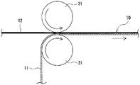
Next, as shown in fig. 1 (b), the positive electrode composite sheet 12 is produced by rolling the positive electrode composite 20 into a sheet shape. Then, as shown in fig. 2, a laminate of the core material 11 and the positive electrode composite material sheet 12 is hot-pressed, and the positive electrode composite material sheet 12 is joined to the surface of the core material 11. Through the above steps, the positive electrode 10 in which the positive electrode composite layer formed of the positive electrode composite sheet 12 is provided on the surface of the core material 11 is manufactured. As will be described in detail later, the positive electrode composite sheet 12 includes a fibrous first binder 22 and a particulate second binder 23.
[ Positive electrode ]
As shown in fig. 3, positive electrode 10 includes core material 11 and positive electrode composite material sheet 12 bonded to the surface of core material 11. Positive electrode composite material sheets 12 are preferably provided on both sides of core material 11. The positive electrode composite material sheet 12 contains a positive electrode active material 21, a fibrous first binder 22, and a particulate second binder 23. The positive electrode 10 may be a long electrode plate constituting a wound electrode body, or may be a rectangular electrode plate constituting a laminated electrode body. The positive electrode 10 is manufactured by bonding a positive electrode composite material sheet 12 to a core material 11 and then cutting the sheet into a predetermined shape and size.
For example, a metal foil having a thickness of 5 to 20 μm can be used as the core material 11. As an example of the metal foil constituting the core member 11, a metal foil containing aluminum, preferably an aluminum alloy foil containing aluminum as a main component (component having the highest mass ratio) and at least 1 metal selected from iron, manganese, copper, magnesium, zirconium, silicon, chromium, titanium, and nickel is used.
The positive electrode composite material sheet 12 is provided on the surface of the core material 11, and constitutes a composite material layer of the positive electrode 10. As described above, the positive electrode composite sheet 12 contains the fibrous first binder 22 and the particulate second binder 23 as binders, and has a thickness of, for example, 30 to 120 μm, preferably 50 to 100 μm. By using the fibrous first binder 22, the positive electrode composite material 20 can be rolled and formed into a sheet shape. In addition, the joining force of the positive electrode composite material sheet 12 to the core material 11 is improved by using the second binder 23 in combination.
To enhance electron conductivity, the positive electrode composite sheet 12 preferably includes a conductive material 24. Examples of the conductive material 24 include carbon materials such as carbon black, acetylene black, ketjen black, and graphite. The content of the conductive material 24 is, for example, 0.5 to 5 mass% with respect to the mass of the positive electrode composite sheet 12. One example of the volume-based median diameter (D50) of the conductive material 24 is 0.05 to 1 μm.
The positive electrode composite sheet 12 is mainly composed of a positive electrode active material 21. The content of the positive electrode active material 21 is preferably 85 to 99% by mass, and more preferably 90 to 98% by mass, based on the mass of the positive electrode composite sheet 12. The D50 of the positive electrode active material 21 is, for example, 1 to 30 μm, preferably 2 to 15 μm, and more preferably 3 to 15 μm. The D50 of the positive electrode active material 21 and the conductive material 24 was measured using a laser diffraction particle size distribution measuring device (LA-920, horiba, ltd.) using water as a dispersion medium.
As the positive electrode active material 21, a lithium transition metal composite oxide is generally used. Examples of the metal element contained In the lithium transition metal composite oxide include Ni, co, mn, al, B, mg, ti, V, cr, fe, cu, zn, ga, sr, zr, nb, in, sn, ta, W, and the like. Among them, at least 1 kind of Ni, co, and Mn is preferably contained. Examples of suitable composite oxides include lithium transition metal composite oxides containing Ni, co, and Mn; a lithium transition metal composite oxide containing Ni, co and Al.
The first binder 22 adheres to the particle surface of the positive electrode active material 21 and intertwines with the positive electrode active material 21. In other words, the positive electrode active material 21 is held by the first binder 22 in a mesh shape, and the sheet shape is maintained. The first bonding material 22 is obtained by fibrillating PTFE particles with, for example, polytetrafluoroethylene (PTFE) as a main component. The first binder material 22 may be composed of only PTFE, or may contain a resin component other than PTFE within a range not impairing the object of the present application. The content of the first binder 22 is, for example, 0.05 to 10 mass%, preferably 0.1 to 8 mass%, and more preferably 0.2 to 5 mass% with respect to the mass of the positive electrode composite material sheet 12.
The second binder 23 contains polyvinylidene fluoride (PVdF) as a main component, and has a volume-based median particle diameter (D50) of 50 μm or less. The D50 of the second binder 23 was measured using a laser diffraction particle size distribution measuring apparatus using water as a dispersion medium, similarly to the positive electrode active material 21. The PVdF is not fibrillated in the process of manufacturing the positive electrode composite material 20, and maintains the state of particles. The second adhesive material 23 may be composed of PVdF alone, or may contain a resin component other than PVdF within a range not impairing the object of the present application. Hereinafter, the second binder 23 will be described as PVdF particles.
As described above, PVdF particles having a D50 of 50 μm or less are used for the second binder 23. By using the first binder 22 and the second binder 23 having a D50 of 50 μm or less in combination, the joining force of the positive electrode composite sheet 12 to the core material 11 is specifically increased, and the peel strength of the positive electrode composite sheet 12 is greatly improved. Even when PVdF particles having a D50 of more than 50 μm are used, the effect of improving the bonding force is not substantially obtained, and the peel strength is hardly changed as compared with the case where only the first adhesive material 22 is used as the adhesive material.
The D50 of the second adhesive 23 is more preferably 40 μm or less, and particularly preferably 30 μm or less. The lower limit of the D50 is not particularly limited, but is preferably 0.1. Mu.m, more preferably 0.5. Mu.m, and particularly preferably 1 μm. An example of a suitable range of the D50 of the second adhesive 23 is 0.5 to 40 μm or 1 to 30 μm. In this case, the joining force of the positive electrode composite material sheet 12 to the core material 11 is more significantly improved. The D50 of the second adhesive material 23 can be controlled to a target range by, for example, adjusting the polymerization conditions of PVdF or by pulverizing the polymerized PVdF.
The content of the second adhesive material 23 is preferably less than that of the first adhesive material 22. As specific examples, the ratio of the first binder material 22 to the second binder material 23= 1.5. The content of the second binder 23 is, for example, 0.1 to 5 mass%, preferably 0.2 to 4 mass%, and more preferably 0.5 to 3 mass% with respect to the mass of the positive electrode composite sheet 12. In this case, the peel strength of the positive electrode composite sheet 12 can be efficiently increased while suppressing an increase in the plate resistance.
In the positive electrode 10, the positive electrode active material 21 may be entrapped in the core material 11. The maximum depth D of the positive electrode active material 21 is, for example, 30% or more of the thickness of the core material 11, and specifically 6 μm or more. Here, the depth D of the positive electrode active material 21 is: the length along the thickness direction of core material 11 from the surface of core material 11 to the deepest portion of positive electrode active material 21. The depth of penetration D can be measured by observing the cross section of the positive electrode 10 using SEM. The maximum depression depth D can be controlled by, for example, the softening temperature of the core material 11, the heating temperature and the pressing pressure in the hot pressing step described later.
In the positive electrode 10, when the positive electrode composite material sheet 12 is defined as a first region and a second region in this order from the core material 11 side by equally dividing the sheet in the thickness direction, the difference (a-b) between the content (a) of the second binder 23 in the first region and the content (b) of the second binder 23 in the second region is preferably within ± 5%. The contents (a) and (b) may be substantially the same.
That is, the second binder 23 is not present unevenly in a part of the positive electrode composite sheet 12, but is present uniformly over the entire sheet. Such uniform distribution of the bonding material can be achieved using a dry method in which movement of the bonding material does not occur. With respect to the first binder material 22, the difference (a-B) between the content (a) of the first binder material 22 in the first region and the content (B) of the first binder material 22 in the second region is also preferably within a range of ± 5%.
The concentration distribution of PVdF particles in the positive electrode composite sheet 12 was measured by the following method.
(1) The positive electrode was immersed in an alkaline solution to convert PVdF in the positive electrode composite sheet into a polyalkylene oxide.
(2) The PVdF in the positive electrode composite material sheet treated in (1) was dyed with bromine Br.
(3) The positive electrode cross section containing the stained PVdF was measured by an Electron Probe Microanalyzer (EPMA), and the concentration distribution of Br was determined and regarded as the concentration distribution of PVdF.
Fig. 4 is a sectional view of a positive electrode composite sheet 13 as another example of the embodiment. As shown in fig. 3, the positive electrode composite material sheet 13 has a multilayer structure including a first sheet 14 and a second sheet 15, the first sheet 14 includes a positive electrode active material 21, a first binder 22, a second binder 23, and a conductive material 24, the second sheet 15 includes the positive electrode active material 21, the first binder 22, and the conductive material 24 and does not substantially include the second binder 23, and the positive electrode composite material sheet 13 is disposed in the order of the first sheet 14 and the second sheet 15 from the core material 11 side. According to the positive electrode composite sheet 13, the peel strength of the positive electrode composite sheet 13 can be efficiently increased while suppressing an increase in the plate resistance.
Both the first sheet 14 and the second sheet 15 are preferably produced by a dry method, and are bonded to each other before a hot pressing step or a hot pressing step described later to form the positive electrode composite sheet 13. The thickness of each sheet is not particularly limited, and each sheet may have substantially the same thickness. Alternatively, the thickness of the first sheet 14 may be thinner than the thickness of the second sheet 15. In addition, the thickness of the second sheet 15 may be thinner than the thickness of the first sheet 14. An example of the thickness of each sheet is 30 to 60 μm. The content of each component in the first sheet 14 is the same as in the case of the positive electrode composite material sheet 12, for example. Since the second sheet 15 does not substantially contain the second binder 23, the content of at least one of the positive electrode active material 21, the first binder 22, and the conductive material 24 can be increased as compared with the first sheet 14.
[ negative electrode ]
The negative electrode includes a core material made of a metal foil and a negative electrode composite layer provided on the surface of the core material. Copper foil is generally used as a negative electrode core material. As the negative electrode, a conventionally known electrode plate manufactured by a wet method may be used, or an electrode plate provided with a negative electrode composite material sheet manufactured by a dry method may be used. The negative electrode may include a negative electrode composite sheet including a fibrous first binder and a particulate second binder, and may have the same configuration as the positive electrode 10.
Examples of the negative electrode active material include natural graphite such as flake graphite, block graphite, and soil graphite; and carbon-based active materials such as artificial graphite, for example, bulk artificial graphite (MAG) and graphitized Mesophase Carbon Microbeads (MCMB). As the negative electrode active material, si-based active materials that are alloyed with lithium, or the like can be used. Since the carbon-based active material has higher electron conductivity than the positive electrode active material 21, the negative electrode may not contain the conductive material 24.
[ nonaqueous electrolyte Secondary Battery ]
A nonaqueous electrolyte secondary battery according to an example of the embodiment includes an electrode body in which the positive electrode 10 and the negative electrode are laminated with a separator interposed therebetween, a nonaqueous electrolyte, and an exterior body for housing the electrode body and the negative electrode. The electrode body may be either a wound electrode body or a laminated electrode body. Examples of the outer package include a cylindrical outer package can, a rectangular outer package can, a coin-shaped outer package can, and an outer package formed of an aluminum laminate sheet.
The nonaqueous electrolyte includes a nonaqueous solvent and an electrolyte salt dissolved in the nonaqueous solvent. Examples of the nonaqueous solvent include esters, ethers, nitriles, amides, and mixed solvents of two or more of them. The nonaqueous solvent may contain a halogen-substituted compound in which at least a part of the hydrogens in these solvents is substituted with a halogen atom such as fluorine. Electrolyte salt such as LiPF 6 And lithium salts are mentioned. The electrolyte is not limited to a liquid electrolyte, and may be a solid electrolyte.
[ method for producing Positive electrode ]
The method for manufacturing the positive electrode 10 will be described in detail below. The following description exemplifies a method for manufacturing the positive electrode 10 containing a conductive material, but the following manufacturing method can be similarly applied to the manufacture of the negative electrode. In the case of the negative electrode, the negative electrode active material is used instead of the positive electrode active material, and the conductive material may not be added to the composite sheet.
As shown in fig. 1 (a), in the manufacturing process of the electrode 10, first, the positive electrode active material 21, the PTFE particles, the PVdF particles (second binder 23), and the conductive material 24 are put into the mixer 40, and the PTFE particles are fibrillated while these materials are mixed to produce the electrode composite 20 (hereinafter, this process is referred to as "first process"). Next, as shown in fig. 1 (b), the electrode composite sheet 12 is produced by rolling and forming the electrode composite 20 into a sheet shape (hereinafter, this step is referred to as "second step"). The manufacturing process is a dry method for manufacturing the electrode 10 by using the electrode composite material 20 having a solid content concentration of substantially 100%.
As the PTFE particles, those having a D50 of 5 to 100 μm are used, for example. In this case, the mixing treatment can be performed in a short time with a low shearing force, and the positive electrode composite sheet 12 with less particle breakage of the positive electrode active material 21, good dispersibility of the constituent materials, and high breaking strength can be obtained. The PTFE particles are fibrillated in a first step to form a fibrous first binder material 22. The second binder 23 is PVdF particles having a D50 of 50 μm or less, preferably 0.5 to 40 μm or 1 to 30 μm. PVdF was not fibrillated in the first process, maintaining the particle shape and D50 prior to mixing.
The mixer 40 may be any known mixer, and preferably a mechanical stirring mixer is used. Specific examples of suitable mixers 40 include: examples of the device capable of imparting a mechanical shearing force include a cutter mill, a pin mill, a bead mill, a grain-compounding device (a device which rotates at a high speed inside a tank and generates a shearing force between a specially-shaped rotor and a striking plate), a pelletizer, a twin-screw extruder, and a mixer such as a planetary mixer. Among them, a cutting mill, a device for making a fine particle composite, a pelletizer or a twin-screw extrusion kneader is preferable.
As shown in fig. 1 (b), in the second step, the electrode composite 20 is rolled with two rolls 30 and formed into a sheet. The two rollers 30 are disposed at a predetermined interval and rotate in the same direction. The electrode composite 20 is compressed by the two rolls 30 by being fed to the gap between the two rolls 30, and is stretched into a sheet shape. The two rollers 30 have, for example, the same roller diameter. The electrode composite sheet 12 thus obtained may be passed through the gap between the two rolls 30 a plurality of times, or may be stretched 1 or more times using another roll having a different roll diameter, peripheral speed, gap, or the like. Alternatively, the electrode composite sheet 12 may be hot-pressed by heating a roll.
The thickness of the electrode composite sheet 12 may be controlled using, for example, the gap between the two rolls 30, the peripheral speed, the number of stretching processes, and the like. In the second step, the electrode composite 20 is preferably formed into a sheet shape using two rolls 30 having a peripheral speed ratio different by 2 times or more. By changing the circumferential speed ratio of the two rolls 30, for example, the electrode composite sheet 12 can be easily made thin, and productivity can be improved. The circumferential speed ratio of the two rolls 30 is preferably 2.5 times or more, and may be 3 times or more. The circumferential speed ratio of the two rollers 30 is, for example, 1.
Next, as shown in fig. 2, the electrode 10 in which the composite material layer formed of the electrode composite material sheet 12 is provided on the surface of the core material 11 is obtained by bonding the electrode composite material sheet 12 to the core material 11 (this step is hereinafter referred to as a "third step"). Fig. 2 shows a state in which electrode composite sheets 12 are bonded to only one surface of core material 11, but electrode composite sheets 12 are preferably bonded to both surfaces of core material 11. The two electrode composite material sheets 12 may be bonded to both surfaces of the core material 11 at the same time, or 1 sheet may be bonded to one surface of the core material 11, and then another 1 sheet may be bonded to the other surface.
In the third step, the electrode composite material sheet 12 is bonded to the surface of the core material 11 using two rollers 31. The two rollers 31 have, for example, the same roller diameter, are arranged with a predetermined gap therebetween, and rotate in the same direction at the same peripheral speed. The two rolls 31 are preferably heated to a predetermined temperature and applied with a predetermined pressure.
As shown in examples described later, the electrode 10 manufactured through the above steps has the positive electrode composite material sheet 12 firmly bonded to the core material 11 and having high peel strength.
< example >
The present application will be further described with reference to the following examples, but the present application is not limited to these examples.
< example 1>
[ preparation of Positive electrode composite Material ]
The positive electrode active material, PTFE particles having a D50 of 10 μm, PVdF particles having a D50 of 25 μm, and acetylene black were mixed at a mass ratio of 100. By this mixing treatment, PTFE particles were fibrillated, and a positive electrode composite material in which an active material, fibrous PTFE, PVdF particles, and acetylene black were uniformly dispersed was obtained. The solid content concentration of the obtained positive electrode composite material was 100%.
[ production of Positive electrode composite Material sheet ]
The obtained positive electrode composite material was rolled while passing between two rolls to prepare a positive electrode composite material sheet. The positive electrode composite material sheet was subjected to multiple stretching treatments with the peripheral speed ratio of the two rolls set at 1.
[ production of Positive electrode ]
The obtained positive electrode composite sheet was disposed on the surface of the core material, and the laminate of the positive electrode composite sheet and the core material was hot-pressed (pressing pressure: 0.2[ t/cm ]) using two rolls heated to 200 ℃. By this hot pressing, a positive electrode in which the positive electrode composite sheet is firmly bonded to the surface of the core material is obtained. An aluminum alloy foil having a thickness of 15 μm was used as the core material.
The peel strength of the positive electrode composite sheet was evaluated for the obtained positive electrode by the following method, and the evaluation results are shown in table 1 together with the D50 of the PVdF particles (second binder) used.
[ evaluation of peeling Strength ]
(1) The positive electrode is fixed to the base with the core material side facing the base.
(2) A part of the positive electrode composite material sheet was peeled off from the fixed positive electrode, and bent at 90 ° with respect to the core material.
(3) A sheet of the positive electrode composite material bent at 90 ° was stretched using a universal tester, and the force necessary for peeling of the sheet was measured as peel strength.
< example 2>
A positive electrode was produced in the same manner as in example 1 except that PVdF particles having a D50 of 10 μm were used as the second binder, and the peel strength was evaluated.
< comparative example 1>
A positive electrode was produced in the same manner as in example 1 except that the second binder was not used, and the peel strength was evaluated.
< comparative example 2>
A positive electrode was produced in the same manner as in example 1 except that PVdF particles having a D50 of 150 μm were used as the second binder, and the peel strength was evaluated.
[ Table 1]

As shown in table 1, it can be seen that: the positive electrodes of the examples all had significantly higher peel strength than the positive electrodes of the comparative examples, and the positive electrode composite material sheets were firmly joined to the core material. The positive electrode of comparative example 2, although containing PVdF particles as the second binder, had the same degree of peel strength as the positive electrode of comparative example 1 containing no PVdF particles. That is, D50 of the second binder material has a significant effect on the peel strength of the positive electrode composite material sheet. When the particle size of the PVdF particles is large, the PVdF particles do not dissolve in the hot pressing step in a short time, and thus a sufficient adhesive force cannot be exhibited, or even if they dissolve, a sufficient adhesion area to the active material particles cannot be secured because they have a very large particle size relative to the active material particles and the amount of the additive is small, and this is considered to be a cause of not improving the peel strength.
As described above, when the second binder having the D50 adjusted to the predetermined range is used together with the fibrous first binder, the peel strength of the positive electrode composite sheet is specifically improved. Table 1 shows the evaluation results obtained by using the second adhesive having D50 of 10 μm and 25 μm, and high peel strength can be obtained when D50 is 50 μm or less, preferably in the range of 1 to 30 μm.
Description of the reference numerals
10. Positive electrode
11. Core material
12. 13 positive electrode composite material sheet
14. First sheet
15. Second sheet
20. Positive electrode composite material
21. Positive electrode active material
22. First adhesive material
23. Second adhesive material
24. Conductive material
30. 31 roller
40. Mixing machine
Claims (6)
1. An electrode for a secondary battery, comprising:
a core material; and
an electrode composite material sheet bonded to a surface of the core material,
the electrode composite sheet comprises an active material, a fibrous first binder, and a particulate second binder, wherein the second binder comprises polyvinylidene fluoride as a main component, and has a volume-based median particle diameter of 50 [ mu ] m or less.
2. The electrode for a secondary battery according to claim 1, wherein when the electrode composite material sheet is bisected in the thickness direction and defined as a first region and a second region in this order from the core material side, the difference between the content (a) of the second binder in the first region and the content (b) of the second binder in the second region is within a range of ± 5%.
3. The electrode for a secondary battery according to claim 1, wherein the electrode composite sheet has a multilayer structure comprising a first sheet and a second sheet,
the first sheet contains the active substance, the first adhesive material, the second adhesive material, and a conductive material,
the second sheet comprising the active, the first bonding material, and the conductive material, and being substantially free of the second bonding material,
the secondary battery electrode is arranged in the order of the first sheet and the second sheet from the core material side.
4. The electrode for a secondary battery according to any one of claims 1 to 3, wherein the first binder contains polytetrafluoroethylene as a main component.
5. The electrode for a secondary battery according to any one of claims 1 to 4, wherein a content of the second binder is less than a content of the first binder,
the first binder material is contained in an amount of 0.05 to 10 mass% with respect to the mass of the electrode composite material sheet,
the second binder is contained in an amount of 0.1 to 5 mass% with respect to the mass of the electrode composite sheet.
6. A method for producing an electrode for a secondary battery, wherein an active material, a fibrous first binder, and a particulate second binder containing polyvinylidene fluoride as a main component and having a volume-based median particle diameter of 50 [ mu ] m or less are mixed without using a solvent to prepare an electrode composite having a solid content concentration of substantially 100%,
rolling the electrode composite material to form a sheet, thereby producing an electrode composite material sheet,
and hot-pressing the laminate of the electrode composite material sheet and a core material to bond the electrode composite material sheet to the surface of the core material.
Applications Claiming Priority (3)
| Application Number | Priority Date | Filing Date | Title |
|---|---|---|---|
| JP2020052754 | 2020-03-24 | ||
| JP2020-052754 | 2020-03-24 | ||
| PCT/JP2021/001563 WO2021192541A1 (en) | 2020-03-24 | 2021-01-19 | Electrode for secondary batteries and method for producing same |
Publications (1)
| Publication Number | Publication Date |
|---|---|
| CN115336030A true CN115336030A (en) | 2022-11-11 |
Family
ID=77890100
Family Applications (1)
| Application Number | Title | Priority Date | Filing Date |
|---|---|---|---|
| CN202180021893.6A Pending CN115336030A (en) | 2020-03-24 | 2021-01-19 | Electrode for secondary battery and method for manufacturing same |
Country Status (5)
| Country | Link |
|---|---|
| US (1) | US20230108728A1 (en) |
| EP (1) | EP4131458A1 (en) |
| JP (1) | JPWO2021192541A1 (en) |
| CN (1) | CN115336030A (en) |
| WO (1) | WO2021192541A1 (en) |
Families Citing this family (1)
| Publication number | Priority date | Publication date | Assignee | Title |
|---|---|---|---|---|
| TW202345445A (en) * | 2022-03-02 | 2023-11-16 | 日商大金工業股份有限公司 | Secondary battery mixture, secondary battery mixture sheet, secondary battery mixture sheet manufacturing method, and secondary battery |
Family Cites Families (9)
| Publication number | Priority date | Publication date | Assignee | Title |
|---|---|---|---|---|
| FR2764442B1 (en) * | 1997-06-05 | 1999-07-30 | Alsthom Cge Alcatel | EMPATED NICKEL ELECTRODE |
| JP4059556B2 (en) * | 1998-03-26 | 2008-03-12 | 三洋電機株式会社 | Non-aqueous electrolyte battery and manufacturing method thereof |
| JP2000149954A (en) * | 1998-11-11 | 2000-05-30 | Sanyo Electric Co Ltd | Nonaqueous electrolyte battery, and its manufacture |
| JP2001307716A (en) * | 2000-02-16 | 2001-11-02 | Nisshinbo Ind Inc | Multilayer electrode structure, battery using the same, electrical double layer capacitor, and their manufacturing methods |
| JP2011258333A (en) * | 2010-06-07 | 2011-12-22 | Asahi Glass Co Ltd | Method of manufacturing electrode composite for secondary battery, electrode for secondary battery and secondary battery |
| JP2013065478A (en) | 2011-09-19 | 2013-04-11 | Toyota Motor Corp | Method for manufacturing lithium ion secondary battery |
| JP6398995B2 (en) * | 2014-01-16 | 2018-10-03 | 日本ゼオン株式会社 | Binder composition for secondary battery electrode, slurry composition for secondary battery electrode, electrode for secondary battery, and secondary battery |
| CN113223860B (en) * | 2014-04-18 | 2023-08-08 | 特斯拉公司 | Dry energy storage device electrode and method for manufacturing same |
| US11870057B2 (en) * | 2018-02-06 | 2024-01-09 | Navitas Systems, Llc | Dry process formation of solid state lithium ion cell |
-
2021
- 2021-01-19 CN CN202180021893.6A patent/CN115336030A/en active Pending
- 2021-01-19 JP JP2022509312A patent/JPWO2021192541A1/ja active Pending
- 2021-01-19 WO PCT/JP2021/001563 patent/WO2021192541A1/en unknown
- 2021-01-19 EP EP21776906.6A patent/EP4131458A1/en active Pending
- 2021-01-19 US US17/911,507 patent/US20230108728A1/en active Pending
Also Published As
| Publication number | Publication date |
|---|---|
| US20230108728A1 (en) | 2023-04-06 |
| WO2021192541A1 (en) | 2021-09-30 |
| EP4131458A1 (en) | 2023-02-08 |
| JPWO2021192541A1 (en) | 2021-09-30 |
Similar Documents
| Publication | Publication Date | Title |
|---|---|---|
| WO2022024520A1 (en) | Ptfe powder, method for producing electrode, and electrode | |
| WO2021181887A1 (en) | Method for producing electrode and electrode mixture | |
| CN115336030A (en) | Electrode for secondary battery and method for manufacturing same | |
| WO2022070542A1 (en) | Electrode and method for producing electrode | |
| EP4057372A1 (en) | Method for producing secondary battery electrode and method for producing secondary battery | |
| EP4120383A1 (en) | Electrode for secondary battery and method for producing the same | |
| EP4254539A1 (en) | Electrode and electrode manufacturing method | |
| EP4254540A1 (en) | Electrode and method for producing electrode | |
| WO2023032391A1 (en) | Electrode | |
| WO2023119814A1 (en) | Electrode, non-aqueous electrolyte secondary battery, and electrode manufacturing method | |
| WO2022163186A1 (en) | Electrode and electrode manufacturing method | |
| WO2023007962A1 (en) | Electrode | |
| EP4283697A1 (en) | Method and apparatus for preparing dry electrode sheet for secondary battery, dry electrode sheet for secondary battery, electrode for secondary battery and secondary battery | |
| CN116472620A (en) | Electrode and method for manufacturing electrode | |
| WO2023182030A1 (en) | Electrode, nonaqueous electrolyte secondary battery and method for producing electrode | |
| WO2022018954A1 (en) | Positive electrode for batteries, and battery | |
| CN115207272A (en) | Electrode, secondary battery including the same, and method of manufacturing the same | |
| JP2023073649A (en) | Electrode manufacturing method and electrode |
Legal Events
| Date | Code | Title | Description |
|---|---|---|---|
| PB01 | Publication | ||
| PB01 | Publication | ||
| SE01 | Entry into force of request for substantive examination | ||
| SE01 | Entry into force of request for substantive examination |