CN115327553A - Rapid laser radar sample generation method for inducing variation - Google Patents
Rapid laser radar sample generation method for inducing variation Download PDFInfo
- Publication number
- CN115327553A CN115327553A CN202211245342.0A CN202211245342A CN115327553A CN 115327553 A CN115327553 A CN 115327553A CN 202211245342 A CN202211245342 A CN 202211245342A CN 115327553 A CN115327553 A CN 115327553A
- Authority
- CN
- China
- Prior art keywords
- point cloud
- driving environment
- laser radar
- sample
- cluster
- Prior art date
- Legal status (The legal status is an assumption and is not a legal conclusion. Google has not performed a legal analysis and makes no representation as to the accuracy of the status listed.)
- Granted
Links
Images


Classifications
-
- G—PHYSICS
- G01—MEASURING; TESTING
- G01S—RADIO DIRECTION-FINDING; RADIO NAVIGATION; DETERMINING DISTANCE OR VELOCITY BY USE OF RADIO WAVES; LOCATING OR PRESENCE-DETECTING BY USE OF THE REFLECTION OR RERADIATION OF RADIO WAVES; ANALOGOUS ARRANGEMENTS USING OTHER WAVES
- G01S17/00—Systems using the reflection or reradiation of electromagnetic waves other than radio waves, e.g. lidar systems
- G01S17/02—Systems using the reflection of electromagnetic waves other than radio waves
- G01S17/06—Systems determining position data of a target
-
- G—PHYSICS
- G01—MEASURING; TESTING
- G01S—RADIO DIRECTION-FINDING; RADIO NAVIGATION; DETERMINING DISTANCE OR VELOCITY BY USE OF RADIO WAVES; LOCATING OR PRESENCE-DETECTING BY USE OF THE REFLECTION OR RERADIATION OF RADIO WAVES; ANALOGOUS ARRANGEMENTS USING OTHER WAVES
- G01S17/00—Systems using the reflection or reradiation of electromagnetic waves other than radio waves, e.g. lidar systems
- G01S17/88—Lidar systems specially adapted for specific applications
- G01S17/93—Lidar systems specially adapted for specific applications for anti-collision purposes
Landscapes
- Physics & Mathematics (AREA)
- Engineering & Computer Science (AREA)
- Electromagnetism (AREA)
- Computer Networks & Wireless Communication (AREA)
- General Physics & Mathematics (AREA)
- Radar, Positioning & Navigation (AREA)
- Remote Sensing (AREA)
- Optical Radar Systems And Details Thereof (AREA)
Abstract
The invention relates to the technical field of sample generation, and discloses a rapid laser radar sample generation method for inducing variation, which comprises the following steps: collecting driving environment laser radar point cloud characteristic data; carrying out point cloud data aggregation processing on the collected laser radar point cloud characteristic data; extracting linear features of the point cloud data cluster after the aggregation treatment, and reconstructing the linear features by using a multivariate data segmentation technology; a driving environment generated based on the reconstructed topological features; generating a laser radar sample by utilizing an induced variation strategy based on a heuristic algorithm and acquired data, and generating a test driving environment of the laser radar sample; and constructing a driving environment consistency evaluation model, and if the consistency of the real driving environment and the test driving environment is higher, indicating that the generated sample is effective. The method realizes the rapid laser radar sample generation based on the induced variation strategy, and the effective laser radar sample is rapidly generated based on the sample effectiveness judgment of the driving environment consistency evaluation.
Description
Technical Field
The invention relates to the technical field of sample generation, in particular to a rapid laser radar sample generation method for inducing variation.
Background
The laser radar is an environment perception sensor of the unmanned detection vehicle, can generate three-dimensional point cloud data which is superior to two-dimensional data in information expression, and can effectively depict a driving environment. As lidar sensors have become increasingly popular in unmanned vehicles, the safety and stability of lidar sensors have received increasing attention. The existing unmanned detection vehicle independent detection depends on a large amount of training sample spaces, and due to the difference of running environments, the laser radar input domain space is difficult to cover all possible running scenes, so that certain potential safety and stability hazards exist. Aiming at the problem, the invention provides a rapid laser radar sample generation method for inducing variation, which can improve the generation speed of a laser radar sample and enhance the robustness of the sample while ensuring the effectiveness of the laser radar sample.
Disclosure of Invention
In view of the above, the invention provides a rapid laser radar sample generation method for inducing variation, which aims to obtain point cloud data of a laser radar, evaluate the point cloud data through point cloud coordinates and point cloud intensity of the point cloud data, and determine the probability of inducing the point cloud data according to evaluation results of different point cloud data, wherein the probability of inducing variation of the point cloud data is higher when the point cloud intensity is higher as the number of neighborhood point clouds is larger, and the probability of inducing variation of the point cloud data is higher when the number of neighborhood point clouds is larger and the point cloud data with the larger point cloud intensity is larger, so that the generation of an abnormal laser radar sample is avoided, and the generation of the laser radar sample is rapidly realized based on a heuristic optimization algorithm; the collected laser radar point cloud characteristic data and the generated laser radar sample are respectively constructed into a real driving environment and a test driving environment of the unmanned vehicle, the consistency of the two environments is compared, if the consistency is higher, the generated laser radar sample can effectively describe the real driving environment of the unmanned vehicle, namely the generated laser radar sample has higher effectiveness, and the sample robustness of the autonomous detection model of the unmanned detection vehicle is trained through quickly generating the effective laser radar sample.
The invention provides a method for generating a rapid laser radar sample for inducing variation, which comprises the following steps:
s1: collecting laser radar point cloud characteristic data of an unmanned detection vehicle running environment, wherein the laser radar point cloud characteristic data comprise point cloud number, coordinates and intensity information;
s2: carrying out point cloud data aggregation processing on the collected laser radar point cloud characteristic data to obtain a point cloud data cluster;
s3: extracting linear features of the point cloud data clusters after aggregation processing, and reconstructing the linear features by using a multivariate data segmentation technology to obtain reconstructed topological features;
s4: generating a driving environment of the unmanned detection vehicle based on the reconstructed topological feature and the minimum description length frame, wherein the driving environment generated based on the collected data is a real driving environment;
s5: generating a laser radar sample by using an induced variation strategy based on a heuristic algorithm and the acquired data, and generating a test driving environment for the generated laser radar sample according to the steps S2, S3 and S4;
s6: and constructing a driving environment consistency evaluation model, outputting the real driving environment and the test driving environment to the model, outputting similarity evaluation results of the real driving environment and the test driving environment by the model, if the similarity evaluation results are greater than a preset threshold value, indicating that the generated laser radar sample is effective, otherwise indicating that the generated sample is invalid.
As a further improvement of the method of the invention:
optionally, the collecting of the laser radar point cloud characteristic data of the driving environment of the unmanned vehicle in the step S1 includes: the method comprises the following steps that a laser radar of the unmanned detection vehicle emits laser beams to the surroundings in the vehicle driving process, the laser beams detect to obtain position coordinates and surface materials of objects in the surroundings, a returned result set of the laser beam detection is used as laser radar point cloud characteristic data, and the laser radar point cloud characteristic data of the driving environment of the unmanned detection vehicle in the normal driving process are collected;
the laser radar point cloud characteristic data comprise point cloud quantity, coordinates and intensity information, each point cloud represents a detection result of a laser beam emitted by a laser radar, a point cloud set represents the laser radar point cloud characteristic data, the point cloud quantity is equal to the number of the laser beams emitted by the laser radar, the point cloud coordinates are position coordinates of an object detected by the laser beams, the point cloud intensity is the intensity of reflected laser beams, the surface materials of the object are different, and the intensities of the reflected laser beams are different;
the laser radar point cloud characteristic data is as follows:


wherein:


n represents the number of point clouds.
Optionally, the step S2 of performing point cloud data aggregation processing on the collected laser radar point cloud feature data to obtain a point cloud data cluster, including: carrying out aggregation processing on the point cloud data in the laser radar point cloud characteristic data, taking an aggregation result as a point cloud data cluster, wherein the point cloud data aggregation processing flow comprises the following steps:
s21: placing n point clouds in the laser radar point cloud characteristic data in a three-dimensional coordinate system of the constructed unmanned detection vehicle driving area, wherein the point cloud coordinates are coordinates of the point clouds in the three-dimensional coordinate system;
s22: extracting coordinate values of all point clouds on a Z axis to form a point cloud Z axis coordinate set;
s23: initializing a Z-axis cluster, wherein the Z-axis cluster is initially empty, selecting point cloud with the maximum coordinate axis from a point cloud Z-axis coordinate set as a cluster center in the Z-axis cluster, and enabling the distance between the point cloud and the cluster center to be smaller than that Adding the point cloud into the Z-axis cluster, and deleting the Z-axis coordinate value corresponding to the point cloud in the Z-axis cluster from the point cloud Z-axis coordinate set, wherein
 Setting the distance threshold value as 5 meters, wherein the distance calculation formula of any two point clouds is as follows:

wherein:


s24: repeating steps S22 and S23 to obtain Each Z-axis cluster comprises a plurality of point clouds;
s25: for any purposeSelecting three point clouds to form a candidate plane, selecting the plane with the most point clouds in the candidate plane as a plane cluster, deleting the point clouds belonging to the plane cluster in the Z-axis cluster, repeating the steps, and decomposing each Z-axis cluster into A planar cluster;
s26: subjecting the obtained product to A Z-axis cluster and
 the individual plane clusters serve as point cloud data clusters.
Optionally, the extracting linear features of the point cloud data cluster after aggregation processing in the step S3, and reconstructing the linear features by using a multivariate data segmentation technology, includes:
the linear feature extraction process of the point cloud data cluster comprises the following steps:
extracting intersecting lines of adjacent plane clusters in the point cloud data clusters as intersecting line characteristics;
extracting the intersection line of adjacent Z-axis clusters in the point cloud data cluster as boundary line characteristics;
taking the intersection lines of the adjacent clusters which do not belong to the intersection line characteristics and the boundary line characteristics as step line characteristics;
the linear features comprise intersecting line features, boundary line features and step line features;
reconstructing the linear characteristics by using a multivariate segmentation technology to obtain reconstructed topological characteristics, wherein the reconstruction process of the linear characteristics comprises the following steps:
s31: taking the plane clusters with the intersecting line characteristics as plane clusters of the same plane area, and taking two plane clusters with the boundary line characteristics or the step line characteristics as plane clusters in adjacent space areas;
s32: constructing a hierarchical tree, wherein root nodes of the constructed hierarchical tree are empty, all nodes of the hierarchical tree are plane clusters, the same layer of nodes belong to the same plane area, and the adjacent layer of nodes are plane clusters in the adjacent space area; the closer the distance between the node and the origin of the three-dimensional coordinate system is, the closer the node position of the node on the same layer is to the left, and the lower the node height is, the closer the node is to the root node;
s33: starting from the root node, calculating two adjacent nodes in the order from top to bottom and from left to right ,
, Wherein the nodes are
 In that
 On the right or below, the similarity calculation method is a cosine similarity calculation method, and if the calculated similarity is greater than a preset similarity threshold value
 Then merging the adjacent nodes to obtain a new node, wherein the new node is a merging result of the two plane clusters, and meanwhile, calculating the similarity between the new node and the adjacent nodes;
if the calculated similarity is less than or equal to the preset similarity threshold value Then select
 And its neighboring nodes
 Carrying out similarity calculation;
repeating the step, and merging the plane clusters;
s34: and re-extracting the linear features after the plane clusters are combined, extracting the topological structure features of each plane cluster after the plane clusters are combined, wherein the topological structure features of each plane cluster comprise the area, the number of vertex points, the number of edges and the length of each edge, and taking the re-extracted linear features and the plane cluster topological structure features as the topological features obtained through reconstruction.
Optionally, in the S4 step, generating a real driving environment of the unmanned probe vehicle based on the reconstructed topological feature and the minimum description length frame, where the generating includes:
generating a running environment of the unmanned detection vehicle based on the reconstructed topological features and the minimum description length frame, wherein the generation process of the running environment of the unmanned detection vehicle comprises the following steps:
s41: placing the combined plane cluster and height cluster in a three-dimensional coordinate system to obtain a three-dimensional unmanned detection vehicle running environment, wherein the three-dimensional unmanned detection vehicle running environment has a plurality of isolated clusters and points;
s42: constructing a driving environment description length framework:

wherein:


s43: merging the isolated clusters and points into a distance In the cluster within the range, the driving environment description length frame is minimized, and the combined driving environment model and the topological characteristic are used as the generated final unmanned detection vehicleAnd (5) driving to the environment.
Optionally, in the step S5, generating the laser radar sample by using a heuristic algorithm and an induced variation strategy based on the acquired data, including:
generating a laser radar sample by utilizing an induced variation strategy based on a heuristic algorithm according to the acquired point cloud characteristic data of the laser radar in the driving environment of the unmanned detection vehicle, wherein the generation process of the laser radar sample comprises the following steps:
s51: utilizing a single-hot encoding method to encode the acquired laser radar point cloud characteristic data of the driving environment of the unmanned detection vehicle, wherein the front part of the encoding result is point cloud coordinates, the rear part of the encoding result is point cloud intensity, and the encoding result set is Wherein
 As a point cloud
 N represents the number of point clouds in the collected laser radar point cloud characteristic data of the driving environment of the unmanned detection vehicle; the length of the encoding result of each point cloud is the same;
s52: constructing a point cloud data evaluation model, and evaluating the coding result of the collected n point cloud data by using the point cloud data evaluation model, wherein the coding result is Evaluation result of (2)
 Comprises the following steps:

wherein:


s53: setting the current iteration times of the algorithm as k, the initial value of k as 1 and the maximum value as Max, carrying out Max times of induced variation on the encoding result, and then carrying out the point cloud after the kth iteration Is coded as
 ;
;
S54: calculating the evaluation result of each coding result after the k-1 iteration, wherein the coding result after the 0 th iteration is the initial coding result of the point cloud data after the one-hot coding;
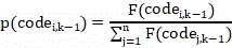
s55: calculating the probability of induced variation of each coding result in the k iteration, and obtaining any coding result Probability of being induced to mutate at kth iteration
 Comprises the following steps:


wherein:


if the result of the encoding is If mutation occurs, the mutation operation flow is: selecting the coding result with the lowest evaluation result after the k-1 iteration
 And randomly select
 The partial coding result in (1) is extracted from the selected partial coding result
 The coding result of the corresponding position in the image;
s56: recording the variation result after variation after each iteration;
s57: if k is<And Max, if k = k +1, returning to the step S54, otherwise, outputting all recorded variation results, and converting the variation results into point cloud data, wherein the number of the point cloud data obtained by conversion is And taking the point cloud data set obtained by conversion as the generated laser radar sample.
Optionally, the step S5 of obtaining a test driving environment from the generated lidar sample according to a driving environment generating method includes:
the driving environment generation method comprises the steps of point cloud data aggregation processing, linear feature extraction reconstruction processing and driving environment generation processing based on a minimum description frame;
and processing the generated laser radar sample according to a running environment generation flow to obtain a test running environment based on the laser radar generated sample.
Optionally, in the step S6, a driving environment consistency evaluation model is built, and the real driving environment and the test driving environment are output to the model, and the model outputs a similarity evaluation result of the real driving environment and the test driving environment, including:
constructing a driving environment consistency evaluation model, wherein the driving environment consistency evaluation model has real driving environment and test driving environment as input, and the driving environment comprises a three-dimensional driving environment model and a corresponding topological structure;
the evaluation flow of the driving environment consistency evaluation model comprises the following steps:
s61: placing a real driving environment model of a three-dimensional structure and a test driving environment model under the same three-dimensional coordinate system;
s62: and calculating to obtain an evaluation result of the driving environment consistency evaluation, wherein the calculation formula is as follows:

wherein: which represents the real driving environment, is,
 representing a test driving environment;


s63: if it is If the laser radar sample is larger than the preset threshold value, the generated laser radar sample is valid, otherwise, the generated sample is invalid, and the valid laser radar sample is used as a training sample for training the autonomous detection model of the unmanned detection vehicle.
Compared with the prior art, the invention provides a rapid laser radar sample generation method for inducing variation, which has the following advantages:
firstly, the scheme provides a rapid generation method of a laser radar sample, which is characterized in that the laser radar sample is generated by utilizing an induced variation strategy based on a heuristic algorithm according to collected point cloud characteristic data of the laser radar in the driving environment of an unmanned vehicle, and the generation flow of the laser radar sample is as follows: utilizing a one-hot encoding method to encode the collected laser radar point cloud characteristic data of the driving environment of the unmanned detection vehicle, wherein the front part of the encoding result is point cloud coordinates, the rear part of the encoding result is point cloud intensity, and the encoding result set is Wherein
 As a point cloud
 N represents the number of point clouds in the collected laser radar point cloud characteristic data of the driving environment of the unmanned detection vehicle; the length of the encoding result of each point cloud is the same; constructing a point cloud data evaluation model, and evaluating the coding result of the collected n point cloud data by using the point cloud data evaluation model, wherein the coding result is
 Evaluation result of (2)
 Comprises the following steps:

wherein: to represent
 The corresponding point cloud data position is
 Number of neighborhood point clouds within the range;
 to represent
 The result of the encoding of the intensity of the point cloud,
 representing the mean value of all point cloud intensity encoding results in the encoding result set,
 representing the result of the encodingEncoding result standard deviations of all point cloud intensities in the set; setting the current iteration number of the algorithm as k, the initial value of k as 1 and the maximum value as Max, carrying out Max induced variation on the encoding result, and carrying out the point cloud after the kth iteration
 Is encoded as
 (ii) a Calculating the evaluation result of each coding result after the k-1 iteration, wherein the coding result after the 0 th iteration is the initial coding result of the point cloud data after the one-hot coding; calculating the probability of induced mutation of each coding result in the k iteration, and obtaining any coding result
 Probability of being induced to mutate at kth iteration
 Comprises the following steps:

wherein: after the k-1 th iteration is shown,
 the corresponding point cloud data position is
 Number of neighborhood point clouds within the range;
 after the k-1 th iteration is shown,
 the result of the encoding of the intensity of the point cloud,
 representing the average value of all point cloud intensity coding results in the coding result set after the (k-1) th iteration,
 representing the standard deviation of all point cloud intensity coding results in the coding result set after the k-1 iteration; if the coded result is
 If mutation occurs, the mutation operation flow is: selecting the coding result with the lowest evaluation result after the k-1 iteration
 And randomly select
 The partial coding result in (1) is extracted from the selected partial coding result
 The coding result of the corresponding position in the image; recording variation results after variation after each iteration, and converting the variation results into point cloud data, wherein the number of the point cloud data obtained by conversion is
 And taking the point cloud data set obtained by conversion as the generated laser radar sample.
According to the scheme, the point cloud data of the laser radar is obtained, the point cloud data are evaluated through the point cloud coordinates and the point cloud intensity of the point cloud data, the probability of point cloud data being induced is determined according to the evaluation results of different point cloud data, the more the neighborhood point clouds are, the higher the point cloud data with the higher point cloud intensity is, the more the neighborhood point clouds and the point cloud data with the higher point cloud intensity are subjected to variation, the probability that the variation result is located in the point cloud data collection range is higher, the generation of an abnormal laser radar sample is avoided, and the generation of the laser radar sample is rapidly realized based on a heuristic optimization algorithm.
Meanwhile, the scheme provides an effectiveness measuring method of a generated sample, a test driving environment is obtained by using the generated laser radar sample according to a driving environment generating method, and the driving environment generating method comprises the processes of point cloud data aggregation processing, linear feature extraction reconstruction processing and driving environment generating processing based on a minimum description frame; constructing a driving environment consistency evaluation model, wherein the driving environment consistency evaluation model has real driving environment and test driving environment as input, and the driving environment comprises a three-dimensional driving environment model and a corresponding topological structure; the evaluation flow of the driving environment consistency evaluation model comprises the following steps: placing a real driving environment model of a three-dimensional structure and a test driving environment model under the same three-dimensional coordinate system; and calculating to obtain an evaluation result of the driving environment consistency evaluation, wherein the calculation formula is as follows:

wherein: which represents the real driving environment, is,
 representing a test driving environment;
 arbitrary vertex coordinates representing a model of a real running environment in a three-dimensional structure,
 in representing three-dimensional structuresTesting the coordinates of any vertex of the driving environment model,
 any vertex pair associated with a linear feature representing a successful match of the real driving environment with the test environment,
 a vertex pair set associated with linear features representing successful matching of the real driving environment and the test environment;
 a topological feature representing a real driving environment,
 a topological feature representing a test driving environment;
 representing a cosine similarity algorithm;
 representing the consistency evaluation result of the real driving environment and the test driving environment; if it is
 If the laser radar sample is larger than the preset threshold value, the generated laser radar sample is effective, otherwise, the generated sample is invalid, and the effective laser radar sample is used as a training sample for the autonomous detection model training of the unmanned detection vehicle. According to the scheme, the collected laser radar point cloud characteristic data and the generated laser radar sample are respectively constructed into the real driving environment and the test driving environment of the unmanned vehicle, the consistency of the two environments is compared, if the consistency is higher, the generated laser radar sample can effectively describe the real driving environment of the unmanned vehicle, namely the generated laser radar sample has higher effectiveness, and the sample robustness of the autonomous detection model of the unmanned vehicle is trained through quickly generating the effective laser radar sample.
Drawings
Fig. 1 is a schematic flowchart illustrating a method for generating a rapid lidar sample for inducing variation according to an embodiment of the present invention;
FIG. 2 is a functional block diagram of an apparatus for generating a rapid laser radar sample with induced variation according to an embodiment of the present invention;
fig. 3 is a schematic structural diagram of an electronic device for implementing a method for generating a rapid lidar sample for inducing variation according to an embodiment of the present invention.
The implementation, functional features and advantages of the present invention will be further described with reference to the accompanying drawings.
Detailed Description
It should be understood that the specific embodiments described herein are merely illustrative of the invention and are not intended to limit the invention.
The embodiment of the application provides a rapid laser radar sample generation method capable of inducing variation. The execution subject of the mutation-inducing fast lidar sample generation method includes, but is not limited to, at least one of electronic devices that a server, a terminal, and the like can be configured to execute the method provided by the embodiments of the present application. In other words, the mutation-inducing fast lidar sample generation method may be performed by software or hardware installed in a terminal device or a server device, and the software may be a blockchain platform. The server includes but is not limited to: a single server, a server cluster, a cloud server or a cloud server cluster, and the like.
Example 1:
s1: collecting laser radar point cloud characteristic data of the driving environment of the unmanned detection vehicle, wherein the laser radar point cloud characteristic data comprises point cloud number, coordinates and intensity information.
The method comprises the following steps of S1, collecting laser radar point cloud characteristic data of the running environment of the unmanned detection vehicle, wherein the method comprises the following steps:
the method comprises the following steps that a laser radar of the unmanned detection vehicle emits laser beams to the surroundings in the vehicle driving process, the laser beams detect to obtain position coordinates and surface materials of objects in the surroundings, a returned result set of the laser beam detection is used as laser radar point cloud characteristic data, and the laser radar point cloud characteristic data of the driving environment of the unmanned detection vehicle in the normal driving process are collected;
the laser radar point cloud characteristic data comprise point cloud quantity, coordinates and intensity information, each point cloud represents a detection result of a laser beam emitted by a laser radar, a point cloud set represents the laser radar point cloud characteristic data, the point cloud quantity is equal to the number of the laser beams emitted by the laser radar, the point cloud coordinates are position coordinates of an object detected by the laser beams, the point cloud intensity is the intensity of reflected laser beams, the surface materials of the object are different, and the intensities of the reflected laser beams are different;
the laser radar point cloud characteristic data is as follows:


wherein:


n represents the number of point clouds.
S2: and carrying out point cloud data aggregation processing on the collected laser radar point cloud characteristic data to obtain a point cloud data cluster.
And in the step S2, point cloud data aggregation processing is carried out on the collected laser radar point cloud characteristic data to obtain a point cloud data cluster, and the method comprises the following steps:
carrying out aggregation processing on the point cloud data in the laser radar point cloud characteristic data, taking an aggregation result as a point cloud data cluster, wherein the point cloud data aggregation processing flow comprises the following steps:
s21: placing n point clouds in the laser radar point cloud characteristic data in a three-dimensional coordinate system of the constructed unmanned detection vehicle driving area, wherein the point cloud coordinates are coordinates of the point clouds in the three-dimensional coordinate system;
s22: extracting coordinate values of all point clouds on a Z axis to form a point cloud Z axis coordinate set;
s23: initializing a Z-axis cluster, wherein the Z-axis cluster is initially empty, selecting a point cloud with the maximum coordinate axis from a point cloud Z-axis coordinate set as a cluster center in the Z-axis cluster, and enabling the distance between the point cloud and the cluster center to be smaller than that between the point cloud and the cluster center Adding the point cloud into the Z-axis cluster, and deleting the Z-axis coordinate value corresponding to the point cloud in the Z-axis cluster from the point cloud Z-axis coordinate set, wherein
 Setting the distance threshold value as 5 meters, wherein the distance calculation formula of any two point clouds is as follows:

wherein:


s24: repeating steps S22 and S23 to obtain Each Z-axis cluster comprises a plurality of point clouds;
s25: for any Z-axis cluster, randomly selecting three point clouds to form a candidate plane, selecting the plane with the most point clouds in the candidate plane as a plane cluster, deleting the point clouds belonging to the plane cluster in the Z-axis cluster, repeating the steps, and decomposing each Z-axis cluster into three point clouds A planar cluster;
s26: subjecting the obtained product to A Z-axis cluster and
 and taking the plane clusters as point cloud data clusters.
S3: and extracting linear features of the point cloud data cluster after aggregation processing, and reconstructing the linear features by using a multivariate data segmentation technology to obtain reconstructed topological features.
And S3, extracting linear features of the point cloud data cluster after the aggregation treatment, and reconstructing the linear features by using a multivariate data segmentation technology, wherein the method comprises the following steps:
the linear feature extraction process of the point cloud data cluster comprises the following steps:
extracting intersecting lines of adjacent plane clusters in the point cloud data clusters as intersecting line characteristics;
extracting the intersection line of adjacent Z-axis clusters in the point cloud data cluster as boundary line characteristics;
taking the intersection lines of the adjacent clusters which do not belong to the intersection line characteristics and the boundary line characteristics as step line characteristics;
the linear features comprise intersecting line features, boundary line features and step line features;
reconstructing the linear characteristics by using a multivariate segmentation technology to obtain reconstructed topological characteristics, wherein the reconstruction process of the linear characteristics comprises the following steps:
s31: taking the plane clusters with the intersecting line characteristics as plane clusters of the same plane area, and taking two plane clusters with the boundary line characteristics or the step line characteristics as plane clusters in adjacent space areas;
s32: constructing a hierarchical tree, wherein root nodes of the constructed hierarchical tree are empty, all nodes of the hierarchical tree are plane clusters, the same layer of nodes belong to the same plane area, and the adjacent layer of nodes are plane clusters in the adjacent space area; the closer the node is to the origin of the three-dimensional coordinate system, the more left the node position of the node on the same layer is, and the lower the node height is, the closer the node is to the root node;
s33: starting from the root node, calculating two adjacent nodes in the order from top to bottom and from left to right ,
, Wherein the nodes are
 In that
 On the right or below, the similarity calculation method is a cosine similarity calculation method, and if the calculated similarity is greater than a preset similarity threshold value
 If so, merging the adjacent nodes to obtain a new node, wherein the new node is a merging result of the two plane clusters, and meanwhile, calculating the similarity between the new node and the adjacent nodes;
if it is calculated to obtainIs less than or equal to a preset similarity threshold Then select
 And its neighboring nodes
 Carrying out similarity calculation;
repeating the step, and merging the plane clusters;
s34: and re-extracting the linear features after the plane clusters are combined, extracting the topological structure features of each plane cluster after the plane clusters are combined, wherein the topological structure features of each plane cluster comprise the area, the number of vertex points, the number of edges and the length of each edge, and taking the re-extracted linear features and the plane cluster topological structure features as the topological features obtained through reconstruction.
S4: and generating a driving environment of the unmanned detection vehicle based on the reconstructed topological characteristic and the minimum description length frame, wherein the driving environment generated based on the collected data is a real driving environment.
And in the step S4, generating a real driving environment of the unmanned detection vehicle based on the reconstructed topological feature and the minimum description length frame, wherein the method comprises the following steps:
generating a running environment of the unmanned detection vehicle based on the reconstructed topological features and the minimum description length frame, wherein the generation process of the running environment of the unmanned detection vehicle comprises the following steps:
s41: placing the combined plane cluster and height cluster in a three-dimensional coordinate system to obtain a three-dimensional unmanned detection vehicle running environment, wherein the three-dimensional unmanned detection vehicle running environment has a plurality of isolated clusters and points;
s42: constructing a driving environment description length framework:

wherein:


s43: merging the isolated clusters and points into a range In the clusters in the range, the driving environment description length frame is minimized, and the combined driving environment model and the topological characteristics are used as the generated final driving environment of the unmanned detection vehicle.
S5: and generating a laser radar sample by using an induced variation strategy based on a heuristic algorithm and the acquired data, and generating a test driving environment for the generated laser radar sample according to the steps S2, S3 and S4.
In the step S5, a laser radar sample is generated by using an induced variation strategy based on a heuristic algorithm and the acquired data, including:
generating a laser radar sample by utilizing an induced variation strategy based on a heuristic algorithm according to collected laser radar point cloud characteristic data of the driving environment of the unmanned detection vehicle, wherein the generation flow of the laser radar sample is as follows:
s51: utilizing a one-hot encoding method to encode the collected laser radar point cloud characteristic data of the driving environment of the unmanned detection vehicle, wherein the front part of the encoding result is point cloud coordinates, the rear part of the encoding result is point cloud intensity, and the encoding result set is In which
 As a point cloud
 N represents the number of point clouds in the collected laser radar point cloud characteristic data of the driving environment of the unmanned detection vehicle; the length of the encoding result of each point cloud is the same;
s52: establishing a point cloud data evaluation model, and evaluating the coding result of the acquired n points of cloud data by using the point cloud data evaluation model, wherein the coding result is Evaluation result of (2)
 Comprises the following steps:

wherein:


s53: setting the current iteration times of the algorithm as k, the initial value of k as 1 and the maximum value as Max, carrying out Max times of induced variation on the encoding result, and then carrying out the point cloud after the kth iteration Is encoded as
 ;
;
S54: calculating the evaluation result of each coding result after the k-1 iteration, wherein the coding result after the 0 th iteration is the initial coding result of the point cloud data after the one-hot coding;
s55: calculating the probability of induced variation of each coding result in the k iteration, and obtaining any coding result Probability of being induced to mutate at kth iteration
 Comprises the following steps:


wherein:


if the result of the encoding is If mutation occurs, the mutation operation flow is: selecting the coding result with the lowest evaluation result after the k-1 iteration
 And randomly select
 The partial coding result in (1) is extracted from the selected partial coding result
 The coding result of the corresponding position in the image;
s56: recording the variation result after variation after each iteration;
s57: if k is<Max, let k = k +1, return to step S54, noOutputting all the recorded variation results and converting the variation results into point cloud data, wherein the number of the point cloud data obtained by conversion is And taking the point cloud data set obtained by conversion as the generated laser radar sample.
In the step S5, the step of obtaining a test driving environment from the generated lidar sample according to a driving environment generating method includes:
the driving environment generation method comprises the steps of point cloud data aggregation processing, linear feature extraction reconstruction processing and driving environment generation processing based on a minimum description frame;
and processing the generated laser radar sample according to a running environment generation flow to obtain a test running environment based on the laser radar generated sample.
S6: and constructing a driving environment consistency evaluation model, outputting the real driving environment and the test driving environment to the model, outputting similarity evaluation results of the real driving environment and the test driving environment by the model, if the similarity evaluation results are greater than a preset threshold value, indicating that the generated laser radar sample is effective, otherwise indicating that the generated sample is invalid.
And S6, constructing a driving environment consistency evaluation model, outputting the real driving environment and the test driving environment to the model, and outputting similarity evaluation results of the real driving environment and the test driving environment by the model, wherein the similarity evaluation results comprise:
constructing a driving environment consistency evaluation model, wherein the driving environment consistency evaluation model has real driving environment and test driving environment as input, and the driving environment comprises a three-dimensional driving environment model and a corresponding topological structure;
the evaluation flow of the driving environment consistency evaluation model comprises the following steps:
s61: placing a real driving environment model of a three-dimensional structure and a test driving environment model under the same three-dimensional coordinate system;
s62: and calculating to obtain an evaluation result of the driving environment consistency evaluation, wherein the calculation formula is as follows:

wherein: which represents the real driving environment, is,
 representing a test driving environment;


s63: if it is If the laser radar sample is larger than the preset threshold value, the generated laser radar sample is valid, otherwise, the generated sample is invalid, and the valid laser radar sample is used as a training sample for training the autonomous detection model of the unmanned detection vehicle.
Example 2:
fig. 2 is a functional block diagram of an apparatus for generating a rapid lidar sample with induced variation according to an embodiment of the present invention, which can implement the method for generating a rapid lidar sample in embodiment 1.
The mutation-inducing rapid lidar sample generation apparatus 100 of the present invention may be installed in an electronic device. According to the realized function, the rapid laser radar sample generation device for inducing variation may include a data acquisition and processing module 101, a driving environment construction module 102, and a laser radar sample generation module 103. The module of the present invention, which may also be referred to as a unit, refers to a series of computer program segments that can be executed by a processor of an electronic device and that can perform a fixed function, and that are stored in a memory of the electronic device.
The data acquisition processing module 101 is used for acquiring the point cloud characteristic data of the laser radar in the driving environment of the unmanned detection vehicle, and performing point cloud data aggregation processing and topological feature extraction processing;
a driving environment construction module 102, configured to generate a driving environment of the unmanned probe vehicle based on the reconstructed topological feature and the minimum description length frame;
the laser radar sample generation module 103 is configured to generate a laser radar sample based on a heuristic algorithm and an induced variation strategy of the acquired data, generate a test driving environment based on the generated laser radar sample, construct a driving environment consistency evaluation model, output the real driving environment and the test driving environment to the model, output a similarity evaluation result of the real driving environment and the test driving environment by the model, and indicate that the generated laser radar sample is valid if the similarity evaluation result is greater than a preset threshold.
In detail, when the modules in the variation-induced rapid lidar sample generation apparatus 100 according to the embodiment of the present invention are used, the same technical means as the variation-induced rapid lidar sample generation method described in fig. 1 above are adopted, and the same technical effects can be produced, which is not described herein again.
Example 3:
fig. 3 is a schematic structural diagram of an electronic device for implementing a method for generating a rapid lidar sample with induced variation according to an embodiment of the present invention.
The electronic device 1 may comprise a processor 10, a memory 11 and a bus, and may further comprise a computer program, such as a program 12, stored in the memory 11 and executable on the processor 10.
The memory 11 includes at least one type of readable storage medium, which includes flash memory, removable hard disk, multimedia card, card-type memory (e.g., SD or DX memory, etc.), magnetic memory, magnetic disk, optical disk, etc. The memory 11 may in some embodiments be an internal storage unit of the electronic device 1, such as a removable hard disk of the electronic device 1. The memory 11 may also be an external storage device of the electronic device 1 in other embodiments, such as a plug-in mobile hard disk, a Smart Media Card (SMC), a Secure Digital (SD) Card, a Flash memory Card (Flash Card), and the like, which are provided on the electronic device 1. Further, the memory 11 may also include both an internal storage unit and an external storage device of the electronic device 1. The memory 11 may be used not only to store application software installed in the electronic device 1 and various types of data, such as codes of the program 12, but also to temporarily store data that has been output or is to be output.
The processor 10 may be formed of an integrated circuit in some embodiments, for example, a single packaged integrated circuit, or may be formed of a plurality of integrated circuits packaged with the same function or different functions, including one or more Central Processing Units (CPUs), microprocessors, digital Processing chips, graphics processors, and combinations of various control chips. The processor 10 is a Control Unit (Control Unit) of the electronic device, connects various components of the whole electronic device by using various interfaces and lines, and executes various functions and processes data of the electronic device 1 by running or executing programs or modules (programs 12 for realizing laser radar sample generation, etc.) stored in the memory 11 and calling data stored in the memory 11.
The bus may be a Peripheral Component Interconnect (PCI) bus, an Extended Industry Standard Architecture (EISA) bus, or the like. The bus may be divided into an address bus, a data bus, a control bus, etc. The bus is arranged to enable connection communication between the memory 11 and at least one processor 10 or the like.
Fig. 3 shows only an electronic device with components, and it will be understood by those skilled in the art that the structure shown in fig. 3 does not constitute a limitation of the electronic device 1, and may comprise fewer or more components than those shown, or some components may be combined, or a different arrangement of components.
For example, although not shown, the electronic device 1 may further include a power supply (such as a battery) for supplying power to each component, and preferably, the power supply may be logically connected to the at least one processor 10 through a power management device, so as to implement functions of charge management, discharge management, power consumption management, and the like through the power management device. The power supply may also include any component of one or more dc or ac power sources, recharging devices, power failure detection circuitry, power converters or inverters, power status indicators, and the like. The electronic device 1 may further include various sensors, a bluetooth module, a Wi-Fi module, and the like, which are not described herein again.
Further, the electronic device 1 may further include a communication interface 13, and optionally, the communication interface may include a wired interface and/or a wireless interface (such as a WI-FI interface, a bluetooth interface, etc.), which is generally used for establishing a communication connection between the electronic device 1 and another electronic device.
Optionally, the electronic device 1 may further comprise a user interface, which may be a Display (Display), an input unit (such as a Keyboard), and optionally a standard wired interface, a wireless interface. Alternatively, in some embodiments, the display may be an LED display, a liquid crystal display, a touch-sensitive liquid crystal display, an OLED (Organic Light-Emitting Diode) touch device, or the like. The display, which may also be referred to as a display screen or display unit, is suitable, among other things, for displaying information processed in the electronic device 1 and for displaying a visualized user interface.
It is to be understood that the described embodiments are for purposes of illustration only and that the scope of the appended claims is not limited to such structures.
The program 12 stored in the memory 11 of the electronic device 1 is a combination of instructions that, when executed in the processor 10, enable:
collecting laser radar point cloud characteristic data of an unmanned detection vehicle running environment, wherein the laser radar point cloud characteristic data comprise point cloud number, coordinates and intensity information;
carrying out point cloud data aggregation processing on the collected laser radar point cloud characteristic data to obtain a point cloud data cluster;
extracting linear features of the point cloud data clusters after aggregation processing, and reconstructing the linear features by using a multivariate data segmentation technology to obtain reconstructed topological features;
generating a driving environment of the unmanned detection vehicle based on the reconstructed topological feature and the minimum description length frame, wherein the driving environment generated based on the collected data is a real driving environment;
generating a laser radar sample by utilizing an induced variation strategy based on a heuristic algorithm and acquired data, and generating a test driving environment for the generated laser radar sample;
and constructing a driving environment consistency evaluation model, outputting the real driving environment and the test driving environment to the model, outputting similarity evaluation results of the real driving environment and the test driving environment by the model, if the similarity evaluation results are greater than a preset threshold value, indicating that the generated laser radar sample is effective, otherwise indicating that the generated sample is invalid.
Specifically, the specific implementation method of the processor 10 for the instruction may refer to the description of the relevant steps in the embodiments corresponding to fig. 1 to fig. 3, which is not repeated herein.
It should be noted that, the above numbers of the embodiments of the present invention are only for description, and do not represent the advantages and disadvantages of the embodiments. And the terms "comprises," "comprising," or any other variation thereof, are intended to cover a non-exclusive inclusion, such that a process, apparatus, article, or method that comprises a list of elements does not include only those elements but may include other elements not expressly listed or inherent to such process, apparatus, article, or method. Without further limitation, an element defined by the phrase "comprising a … …" does not exclude the presence of another identical element in a process, apparatus, article, or method that comprises the element.
Through the above description of the embodiments, those skilled in the art will clearly understand that the method of the above embodiments can be implemented by software plus a necessary general hardware platform, and certainly can also be implemented by hardware, but in many cases, the former is a better implementation manner. Based on such understanding, the technical solution of the present invention may be embodied in the form of a software product, which is stored in a storage medium (e.g., ROM/RAM, magnetic disk, optical disk) as described above and includes instructions for enabling a terminal device (e.g., a mobile phone, a computer, a server, or a network device) to execute the method according to the embodiments of the present invention.
The above description is only a preferred embodiment of the present invention, and not intended to limit the scope of the present invention, and all modifications of equivalent structures and equivalent processes, which are made by using the contents of the present specification and the accompanying drawings, or directly or indirectly applied to other related technical fields, are included in the scope of the present invention.
Claims (8)
1. A rapid laser radar sample generation method for inducing variation is characterized by comprising the following steps:
s1: collecting laser radar point cloud characteristic data of an unmanned detection vehicle running environment, wherein the laser radar point cloud characteristic data comprises point cloud number, coordinates and intensity information;
s2: carrying out point cloud data aggregation processing on the collected laser radar point cloud characteristic data to obtain a point cloud data cluster;
s3: extracting linear features of the point cloud data clusters after aggregation processing, and reconstructing the linear features by using a multivariate data segmentation technology to obtain reconstructed topological features;
s4: generating a driving environment of the unmanned detection vehicle based on the reconstructed topological feature and the minimum description length frame, wherein the driving environment generated based on the collected data is a real driving environment;
s5: generating a laser radar sample by using an induced variation strategy based on a heuristic algorithm and the acquired data, and generating a test driving environment for the generated laser radar sample according to the steps S2, S3 and S4;
s6: and constructing a driving environment consistency evaluation model, outputting the real driving environment and the test driving environment to the model, outputting similarity evaluation results of the real driving environment and the test driving environment by the model, if the similarity evaluation results are greater than a preset threshold value, indicating that the generated laser radar sample is effective, otherwise indicating that the generated sample is invalid.
2. The method for generating rapid lidar sample for inducing variation according to claim 1, wherein the collecting of lidar point cloud characteristic data of the driving environment of the unmanned vehicle in step S1 comprises:
the method comprises the following steps that a laser radar of the unmanned detection vehicle emits laser beams to the surroundings in the vehicle driving process, the laser beams detect to obtain position coordinates and surface materials of objects in the surroundings, a returned result set of the laser beam detection is used as laser radar point cloud characteristic data, and the laser radar point cloud characteristic data of the driving environment of the unmanned detection vehicle in the normal driving process are collected;
the laser radar point cloud characteristic data comprise point cloud quantity, coordinates and intensity information, each point cloud represents a detection result of a laser beam emitted by a laser radar, a point cloud set represents the laser radar point cloud characteristic data, the point cloud quantity is equal to the number of the laser beams emitted by the laser radar, the point cloud coordinates are position coordinates of an object detected by the laser beams, the point cloud intensity is the intensity of reflected laser beams, the surface materials of the object are different, and the intensities of the reflected laser beams are different;
the laser radar point cloud characteristic data is as follows:


wherein:


n represents the number of point clouds.
3. The method as claimed in claim 2, wherein the step S2 of performing point cloud data aggregation on the collected lidar point cloud feature data to obtain a point cloud data cluster includes:
performing aggregation processing on point cloud data in the laser radar point cloud feature data, and taking an aggregation result as a point cloud data cluster, wherein the point cloud data aggregation processing flow comprises the following steps:
s21: placing n point clouds in the laser radar point cloud characteristic data in a three-dimensional coordinate system of the constructed unmanned detection vehicle driving area, wherein the point cloud coordinates are coordinates of the point clouds in the three-dimensional coordinate system;
s22: extracting coordinate values of all point clouds on a Z axis to form a point cloud Z axis coordinate set;
s23: initializing a Z-axis cluster, wherein the Z-axis cluster is initially empty, selecting point cloud with the maximum coordinate axis from a point cloud Z-axis coordinate set as a cluster center in the Z-axis cluster, and enabling the distance between the point cloud and the cluster center to be smaller than that Adding the point cloud into the Z-axis cluster, and deleting the Z-axis coordinate value corresponding to the point cloud in the Z-axis cluster from the point cloud Z-axis coordinate set, wherein
 Setting the distance threshold value as 5 meters, wherein the distance calculation formula of any two point clouds is as follows:

wherein:


s24: repeating steps S22 and S23 to obtain Each Z-axis cluster comprises a plurality of point clouds;
s25: for any Z-axis cluster, randomly selecting three point clouds to form a candidate plane, selecting the plane with the most point clouds in the candidate plane as a plane cluster, deleting the point clouds belonging to the plane cluster in the Z-axis cluster, repeating the steps, and decomposing each Z-axis cluster into point clouds A planar cluster;
s26: subjecting the obtained mixture to A Z-axis cluster and
 the individual plane clusters serve as point cloud data clusters.
4. The method for generating rapid lidar samples for inducing variation according to claim 3, wherein the step S3 is to extract linear features of the point cloud data clusters after aggregation processing, and reconstruct the linear features by using a multivariate data segmentation technique, and the method comprises:
the linear feature extraction process of the point cloud data cluster comprises the following steps:
extracting intersecting lines of adjacent plane clusters in the point cloud data clusters as intersecting line features;
extracting the intersection line of adjacent Z-axis clusters in the point cloud data cluster as boundary line characteristics;
taking the intersection lines of the adjacent clusters which do not belong to the intersection line characteristics and the boundary line characteristics as step line characteristics;
the linear features comprise intersecting line features, boundary line features and step line features;
reconstructing the linear characteristics by using a multivariate segmentation technology to obtain reconstructed topological characteristics, wherein the reconstruction process of the linear characteristics comprises the following steps:
s31: taking the plane clusters with the intersecting line characteristics as plane clusters of the same plane area, and taking two plane clusters with the boundary line characteristics or the step line characteristics as plane clusters in adjacent space areas;
s32: constructing a hierarchical tree, wherein root nodes of the constructed hierarchical tree are empty, all nodes of the hierarchical tree are plane clusters, the same layer of nodes belong to the same plane area, and the adjacent layer of nodes are plane clusters in the adjacent space area; the closer the node is to the origin of the three-dimensional coordinate system, the more left the node position of the node on the same layer is, and the lower the node height is, the closer the node is to the root node;
s33: starting from the root node, calculating two adjacent nodes in the order from top to bottom and from left to right ,
, Wherein the nodes
 In that
 On the right or below, the similarity calculation method is a cosine similarity calculation method, and if the calculated similarity is greater than a preset similarity threshold value
 Then merging the adjacent nodes to obtain a new node, wherein the new node is a merging result of the two plane clusters, and meanwhile, calculating the similarity between the new node and the adjacent nodes;
if the calculated similarity is less than or equal to the preset similarity threshold value Then select
 And its neighboring nodes
 Carrying out similarity calculation;
repeating the step, and merging the plane clusters;
s34: and re-extracting the linear features after the plane clusters are combined, extracting the topological structure features of each plane cluster after combination, wherein the topological structure features of each plane cluster comprise the area, the number of vertexes, the number of edges and the length of each edge, and taking the re-extracted linear features and the plane cluster topological structure features as the topological features obtained through reconstruction.
5. The method as claimed in claim 4, wherein the step S4 of generating the real driving environment of the unmanned vehicle based on the reconstructed topological features and the minimum description length frame comprises:
generating a running environment of the unmanned detection vehicle based on the reconstructed topological features and the minimum description length frame, wherein the generation process of the running environment of the unmanned detection vehicle comprises the following steps:
s41: placing the combined plane cluster and height cluster in a three-dimensional coordinate system to obtain a three-dimensional unmanned detection vehicle driving environment, wherein the three-dimensional unmanned detection vehicle driving environment has a plurality of isolated clusters and points;
s42: constructing a running environment description length framework:

wherein:


s43: merging the isolated clusters and points into a range In the clusters within the range, the driving environment description length frame is minimized, and the combined driving environment model and the topological features are used as the generated final driving environment of the unmanned detection vehicle.
6. The method for generating rapid lidar sample for inducing variation according to claim 1, wherein the step S5 obtains the test driving environment from the generated lidar sample according to a driving environment generating method, and comprises:
the driving environment generation method comprises the steps of point cloud data aggregation processing, linear feature extraction reconstruction processing and driving environment generation processing based on a minimum description frame;
and processing the generated laser radar sample according to a running environment generation flow to obtain a test running environment based on the laser radar generated sample.
7. The method as claimed in claim 1, wherein the mutation-inducing fast lidar sample generation process comprises:
generating a laser radar sample by utilizing an induced variation strategy based on a heuristic algorithm according to the acquired point cloud characteristic data of the laser radar in the driving environment of the unmanned detection vehicle, wherein the generation process of the laser radar sample comprises the following steps:
s51: utilizing a single-hot encoding method to encode the acquired laser radar point cloud characteristic data of the driving environment of the unmanned detection vehicle, wherein the front part of the encoding result is point cloud coordinates, the rear part of the encoding result is point cloud intensity, and the encoding result set is Wherein
 As a point cloud
 N represents the number of point clouds in the collected laser radar point cloud characteristic data of the driving environment of the unmanned detection vehicle; the length of the encoding result of each point cloud is the same;
s52: constructing a point cloud data evaluation model, and evaluating the coding result of the collected n point cloud data by using the point cloud data evaluation model, wherein the coding result is Evaluation result of (2)
 Comprises the following steps:

wherein:


s53: setting the current iteration number of the algorithm as k, the initial value of k as 1 and the maximum value as Max, carrying out Max induced variation on the encoding result, and carrying out the point cloud after the kth iteration Is coded as
 ;
;
S54: calculating the evaluation result of each coding result after the k-1 iteration, wherein the coding result after the 0 th iteration is the initial coding result of the point cloud data after the one-hot coding;
S55:calculating the probability of induced variation of each coding result in the k iteration, and obtaining any coding result Probability of being induced to mutate at kth iteration
 Comprises the following steps:


wherein:


if the result of the encoding is If mutation occurs, the mutation operation flow is: selecting the coding result with the lowest evaluation result after the k-1 iteration
 And randomly select
 The partial coding result in (1) is extracted from the selected partial coding result
 The coding result of the corresponding position in the image;
s56: recording a variation result after variation occurs after each iteration;
s57: if k is<And Max, if k = k +1, returning to the step S54, otherwise, outputting all recorded variation results, and converting the variation results into point cloud data, wherein the number of the point cloud data obtained by conversion is And taking the point cloud data set obtained by conversion as the generated laser radar sample.
8. The method as claimed in claim 1, wherein the step S6 is to construct a driving environment consistency evaluation model, and output the real driving environment and the test driving environment to the model, and the model outputs similarity evaluation results of the real driving environment and the test driving environment, including:
constructing a driving environment consistency evaluation model, wherein the driving environment consistency evaluation model has real driving environment and test driving environment as input, and the driving environment comprises a three-dimensional driving environment model and a corresponding topological structure;
the evaluation flow of the driving environment consistency evaluation model comprises the following steps:
s61: placing a real driving environment model of a three-dimensional structure and a test driving environment model under the same three-dimensional coordinate system;
s62: and calculating to obtain an evaluation result of the driving environment consistency evaluation, wherein the calculation formula is as follows:

wherein: which represents the real driving environment, is,
 representing a test driving environment;


s63: if it is If the laser radar sample is larger than the preset threshold value, the generated laser radar sample is effective, otherwise, the generated sample is invalid, and the effective laser radar sample is used as a training sample for the autonomous detection model training of the unmanned detection vehicle.
Priority Applications (1)
| Application Number | Priority Date | Filing Date | Title |
|---|---|---|---|
| CN202211245342.0A CN115327553B (en) | 2022-10-12 | 2022-10-12 | Rapid laser radar sample generation method for inducing variation |
Applications Claiming Priority (1)
| Application Number | Priority Date | Filing Date | Title |
|---|---|---|---|
| CN202211245342.0A CN115327553B (en) | 2022-10-12 | 2022-10-12 | Rapid laser radar sample generation method for inducing variation |
Publications (2)
| Publication Number | Publication Date |
|---|---|
| CN115327553A true CN115327553A (en) | 2022-11-11 |
| CN115327553B CN115327553B (en) | 2023-01-20 |
Family
ID=83913672
Family Applications (1)
| Application Number | Title | Priority Date | Filing Date |
|---|---|---|---|
| CN202211245342.0A Active CN115327553B (en) | 2022-10-12 | 2022-10-12 | Rapid laser radar sample generation method for inducing variation |
Country Status (1)
| Country | Link |
|---|---|
| CN (1) | CN115327553B (en) |
Cited By (1)
| Publication number | Priority date | Publication date | Assignee | Title |
|---|---|---|---|---|
| CN115792944A (en) * | 2023-01-29 | 2023-03-14 | 深圳煜炜光学科技有限公司 | Road rapid calibration method and system matched with laser radar |
Citations (6)
| Publication number | Priority date | Publication date | Assignee | Title |
|---|---|---|---|---|
| CN111882199A (en) * | 2020-07-23 | 2020-11-03 | 深圳慕智科技有限公司 | Automatic driving laser radar data amplification method based on rule variation |
| CN111881029A (en) * | 2020-07-23 | 2020-11-03 | 深圳慕智科技有限公司 | Multi-scene automatic point cloud amplification method for automatic driving |
| US20210284184A1 (en) * | 2020-03-05 | 2021-09-16 | Waymo Llc | Learning point cloud augmentation policies |
| CN114235679A (en) * | 2021-11-15 | 2022-03-25 | 同济大学 | Pavement adhesion coefficient estimation method and system based on laser radar |
| CN114241258A (en) * | 2021-12-09 | 2022-03-25 | 深圳慕智科技有限公司 | Automatic driving radar point cloud data oriented amplification and optimization method |
| CN115063465A (en) * | 2022-06-15 | 2022-09-16 | 华南理工大学 | Unmanned vehicle driving road condition modeling method based on laser radar |
-
2022
- 2022-10-12 CN CN202211245342.0A patent/CN115327553B/en active Active
Patent Citations (6)
| Publication number | Priority date | Publication date | Assignee | Title |
|---|---|---|---|---|
| US20210284184A1 (en) * | 2020-03-05 | 2021-09-16 | Waymo Llc | Learning point cloud augmentation policies |
| CN111882199A (en) * | 2020-07-23 | 2020-11-03 | 深圳慕智科技有限公司 | Automatic driving laser radar data amplification method based on rule variation |
| CN111881029A (en) * | 2020-07-23 | 2020-11-03 | 深圳慕智科技有限公司 | Multi-scene automatic point cloud amplification method for automatic driving |
| CN114235679A (en) * | 2021-11-15 | 2022-03-25 | 同济大学 | Pavement adhesion coefficient estimation method and system based on laser radar |
| CN114241258A (en) * | 2021-12-09 | 2022-03-25 | 深圳慕智科技有限公司 | Automatic driving radar point cloud data oriented amplification and optimization method |
| CN115063465A (en) * | 2022-06-15 | 2022-09-16 | 华南理工大学 | Unmanned vehicle driving road condition modeling method based on laser radar |
Non-Patent Citations (3)
| Title |
|---|
| AN GUO 等: "LiRTest: augmenting LiDAR point clouds for automated testing of autonomous driving systems", 《ISSTA 2022: PROCEEDINGS OF THE 31ST ACM SIGSOFT INTERNATIONAL SYMPOSIUM ON SOFTWARE TESTING AND ANALYSIS》 * |
| VÂNIA NEVES 等: "Combination and mutation strategies to support test data generation in the context of autonomous vehicles", 《INTERNATIONAL JOURNAL OF EMBEDDED SYSTEMS》 * |
| 李秋洁 等: "基于移动激光扫描的靶标叶面积计算方法", 《农业机械学报》 * |
Cited By (2)
| Publication number | Priority date | Publication date | Assignee | Title |
|---|---|---|---|---|
| CN115792944A (en) * | 2023-01-29 | 2023-03-14 | 深圳煜炜光学科技有限公司 | Road rapid calibration method and system matched with laser radar |
| CN115792944B (en) * | 2023-01-29 | 2023-04-25 | 深圳煜炜光学科技有限公司 | Road rapid calibration method and system matched with laser radar |
Also Published As
| Publication number | Publication date |
|---|---|
| CN115327553B (en) | 2023-01-20 |
Similar Documents
| Publication | Publication Date | Title |
|---|---|---|
| Wang et al. | SAT-GCN: Self-attention graph convolutional network-based 3D object detection for autonomous driving | |
| Wang et al. | 3D-CenterNet: 3D object detection network for point clouds with center estimation priority | |
| EP3286691A1 (en) | A method of detecting objects within a 3d environment | |
| CN106133756A (en) | For filtering, split and identify the system without the object in constraint environment | |
| CN108470174B (en) | Obstacle segmentation method and device, computer equipment and readable medium | |
| Wiseman et al. | When an inescapable accident of autonomous vehicles is looming | |
| Galvanin et al. | Extraction of building roof contours from LiDAR data using a Markov-random-field-based approach | |
| CN110569926B (en) | Point cloud classification method based on local edge feature enhancement | |
| CN113537180B (en) | Tree obstacle identification method and device, computer equipment and storage medium | |
| CN115327553B (en) | Rapid laser radar sample generation method for inducing variation | |
| CN112749653A (en) | Pedestrian detection method, device, electronic equipment and storage medium | |
| CN115984662B (en) | Multi-mode data pre-training and identifying method, device, equipment and medium | |
| CN115526924A (en) | Monte Carlo simulated hydrological environment modeling method and system | |
| JP2015036939A (en) | Feature extraction program and information processing apparatus | |
| CN115457492A (en) | Target detection method and device, computer equipment and storage medium | |
| Zhang et al. | Optimal model fitting for building reconstruction from point clouds | |
| CN116883611B (en) | Channel silt distribution active detection and identification method combining GIS channel information | |
| Nguyen et al. | Toward real-time vehicle detection using stereo vision and an evolutionary algorithm | |
| CN115588082A (en) | Method, device and equipment for displaying space digital model in real time and storage medium | |
| JP5928240B2 (en) | Three-dimensional shape interpretation apparatus and program | |
| CN115546743A (en) | Vehicle-road cooperative control method, device, equipment and medium based on attachment coefficient | |
| CN113920269A (en) | Project progress obtaining method and device, electronic equipment and medium | |
| Hui et al. | Power equipment segmentation of 3D point clouds based on geodesic distance with K-means clustering | |
| CN113449555A (en) | Traffic sign recognition method, device, computer equipment and storage medium | |
| CN116402967B (en) | Scene building rapid singulation method, device, computer equipment and storage medium |
Legal Events
| Date | Code | Title | Description |
|---|---|---|---|
| PB01 | Publication | ||
| PB01 | Publication | ||
| SE01 | Entry into force of request for substantive examination | ||
| SE01 | Entry into force of request for substantive examination | ||
| GR01 | Patent grant | ||
| GR01 | Patent grant |