CN115297809A - Modification of existing valve structures for prosthetic heart valve implantation - Google Patents
Modification of existing valve structures for prosthetic heart valve implantation Download PDFInfo
- Publication number
- CN115297809A CN115297809A CN202180021888.5A CN202180021888A CN115297809A CN 115297809 A CN115297809 A CN 115297809A CN 202180021888 A CN202180021888 A CN 202180021888A CN 115297809 A CN115297809 A CN 115297809A
- Authority
- CN
- China
- Prior art keywords
- cutting
- valve
- heart valve
- catheter
- leaflets
- Prior art date
- Legal status (The legal status is an assumption and is not a legal conclusion. Google has not performed a legal analysis and makes no representation as to the accuracy of the status listed.)
- Pending
Links
Images


Classifications
-
- A—HUMAN NECESSITIES
- A61—MEDICAL OR VETERINARY SCIENCE; HYGIENE
- A61F—FILTERS IMPLANTABLE INTO BLOOD VESSELS; PROSTHESES; DEVICES PROVIDING PATENCY TO, OR PREVENTING COLLAPSING OF, TUBULAR STRUCTURES OF THE BODY, e.g. STENTS; ORTHOPAEDIC, NURSING OR CONTRACEPTIVE DEVICES; FOMENTATION; TREATMENT OR PROTECTION OF EYES OR EARS; BANDAGES, DRESSINGS OR ABSORBENT PADS; FIRST-AID KITS
- A61F2/00—Filters implantable into blood vessels; Prostheses, i.e. artificial substitutes or replacements for parts of the body; Appliances for connecting them with the body; Devices providing patency to, or preventing collapsing of, tubular structures of the body, e.g. stents
- A61F2/02—Prostheses implantable into the body
- A61F2/24—Heart valves ; Vascular valves, e.g. venous valves; Heart implants, e.g. passive devices for improving the function of the native valve or the heart muscle; Transmyocardial revascularisation [TMR] devices; Valves implantable in the body
- A61F2/2427—Devices for manipulating or deploying heart valves during implantation
-
- A—HUMAN NECESSITIES
- A61—MEDICAL OR VETERINARY SCIENCE; HYGIENE
- A61B—DIAGNOSIS; SURGERY; IDENTIFICATION
- A61B17/00—Surgical instruments, devices or methods, e.g. tourniquets
- A61B17/32—Surgical cutting instruments
- A61B17/3205—Excision instruments
- A61B17/32053—Punch like cutting instruments, e.g. using a cylindrical or oval knife
-
- A—HUMAN NECESSITIES
- A61—MEDICAL OR VETERINARY SCIENCE; HYGIENE
- A61B—DIAGNOSIS; SURGERY; IDENTIFICATION
- A61B17/00—Surgical instruments, devices or methods, e.g. tourniquets
- A61B17/32—Surgical cutting instruments
- A61B17/3205—Excision instruments
- A61B17/32056—Surgical snare instruments
-
- A—HUMAN NECESSITIES
- A61—MEDICAL OR VETERINARY SCIENCE; HYGIENE
- A61B—DIAGNOSIS; SURGERY; IDENTIFICATION
- A61B17/00—Surgical instruments, devices or methods, e.g. tourniquets
- A61B17/34—Trocars; Puncturing needles
- A61B17/3417—Details of tips or shafts, e.g. grooves, expandable, bendable; Multiple coaxial sliding cannulas, e.g. for dilating
-
- A—HUMAN NECESSITIES
- A61—MEDICAL OR VETERINARY SCIENCE; HYGIENE
- A61B—DIAGNOSIS; SURGERY; IDENTIFICATION
- A61B18/00—Surgical instruments, devices or methods for transferring non-mechanical forms of energy to or from the body
- A61B18/04—Surgical instruments, devices or methods for transferring non-mechanical forms of energy to or from the body by heating
- A61B18/12—Surgical instruments, devices or methods for transferring non-mechanical forms of energy to or from the body by heating by passing a current through the tissue to be heated, e.g. high-frequency current
- A61B18/14—Probes or electrodes therefor
- A61B18/1442—Probes having pivoting end effectors, e.g. forceps
- A61B18/1445—Probes having pivoting end effectors, e.g. forceps at the distal end of a shaft, e.g. forceps or scissors at the end of a rigid rod
-
- A—HUMAN NECESSITIES
- A61—MEDICAL OR VETERINARY SCIENCE; HYGIENE
- A61B—DIAGNOSIS; SURGERY; IDENTIFICATION
- A61B18/00—Surgical instruments, devices or methods for transferring non-mechanical forms of energy to or from the body
- A61B18/04—Surgical instruments, devices or methods for transferring non-mechanical forms of energy to or from the body by heating
- A61B18/12—Surgical instruments, devices or methods for transferring non-mechanical forms of energy to or from the body by heating by passing a current through the tissue to be heated, e.g. high-frequency current
- A61B18/14—Probes or electrodes therefor
- A61B18/1492—Probes or electrodes therefor having a flexible, catheter-like structure, e.g. for heart ablation
-
- A—HUMAN NECESSITIES
- A61—MEDICAL OR VETERINARY SCIENCE; HYGIENE
- A61F—FILTERS IMPLANTABLE INTO BLOOD VESSELS; PROSTHESES; DEVICES PROVIDING PATENCY TO, OR PREVENTING COLLAPSING OF, TUBULAR STRUCTURES OF THE BODY, e.g. STENTS; ORTHOPAEDIC, NURSING OR CONTRACEPTIVE DEVICES; FOMENTATION; TREATMENT OR PROTECTION OF EYES OR EARS; BANDAGES, DRESSINGS OR ABSORBENT PADS; FIRST-AID KITS
- A61F2/00—Filters implantable into blood vessels; Prostheses, i.e. artificial substitutes or replacements for parts of the body; Appliances for connecting them with the body; Devices providing patency to, or preventing collapsing of, tubular structures of the body, e.g. stents
- A61F2/02—Prostheses implantable into the body
- A61F2/24—Heart valves ; Vascular valves, e.g. venous valves; Heart implants, e.g. passive devices for improving the function of the native valve or the heart muscle; Transmyocardial revascularisation [TMR] devices; Valves implantable in the body
- A61F2/2427—Devices for manipulating or deploying heart valves during implantation
- A61F2/243—Deployment by mechanical expansion
- A61F2/2433—Deployment by mechanical expansion using balloon catheter
-
- A—HUMAN NECESSITIES
- A61—MEDICAL OR VETERINARY SCIENCE; HYGIENE
- A61B—DIAGNOSIS; SURGERY; IDENTIFICATION
- A61B17/00—Surgical instruments, devices or methods, e.g. tourniquets
- A61B17/32—Surgical cutting instruments
- A61B17/320016—Endoscopic cutting instruments, e.g. arthroscopes, resectoscopes
-
- A—HUMAN NECESSITIES
- A61—MEDICAL OR VETERINARY SCIENCE; HYGIENE
- A61B—DIAGNOSIS; SURGERY; IDENTIFICATION
- A61B17/00—Surgical instruments, devices or methods, e.g. tourniquets
- A61B17/32—Surgical cutting instruments
- A61B17/3205—Excision instruments
- A61B17/3207—Atherectomy devices working by cutting or abrading; Similar devices specially adapted for non-vascular obstructions
- A61B17/320783—Atherectomy devices working by cutting or abrading; Similar devices specially adapted for non-vascular obstructions through side-hole, e.g. sliding or rotating cutter inside catheter
-
- A—HUMAN NECESSITIES
- A61—MEDICAL OR VETERINARY SCIENCE; HYGIENE
- A61B—DIAGNOSIS; SURGERY; IDENTIFICATION
- A61B17/00—Surgical instruments, devices or methods, e.g. tourniquets
- A61B17/00234—Surgical instruments, devices or methods, e.g. tourniquets for minimally invasive surgery
- A61B2017/00349—Needle-like instruments having hook or barb-like gripping means, e.g. for grasping suture or tissue
-
- A—HUMAN NECESSITIES
- A61—MEDICAL OR VETERINARY SCIENCE; HYGIENE
- A61B—DIAGNOSIS; SURGERY; IDENTIFICATION
- A61B17/00—Surgical instruments, devices or methods, e.g. tourniquets
- A61B2017/00743—Type of operation; Specification of treatment sites
- A61B2017/00778—Operations on blood vessels
- A61B2017/00783—Valvuloplasty
-
- A—HUMAN NECESSITIES
- A61—MEDICAL OR VETERINARY SCIENCE; HYGIENE
- A61B—DIAGNOSIS; SURGERY; IDENTIFICATION
- A61B17/00—Surgical instruments, devices or methods, e.g. tourniquets
- A61B2017/00831—Material properties
- A61B2017/00867—Material properties shape memory effect
-
- A—HUMAN NECESSITIES
- A61—MEDICAL OR VETERINARY SCIENCE; HYGIENE
- A61B—DIAGNOSIS; SURGERY; IDENTIFICATION
- A61B17/00—Surgical instruments, devices or methods, e.g. tourniquets
- A61B17/22—Implements for squeezing-off ulcers or the like on the inside of inner organs of the body; Implements for scraping-out cavities of body organs, e.g. bones; Calculus removers; Calculus smashing apparatus; Apparatus for removing obstructions in blood vessels, not otherwise provided for
- A61B2017/22097—Valve removal in veins
-
- A—HUMAN NECESSITIES
- A61—MEDICAL OR VETERINARY SCIENCE; HYGIENE
- A61B—DIAGNOSIS; SURGERY; IDENTIFICATION
- A61B17/00—Surgical instruments, devices or methods, e.g. tourniquets
- A61B17/28—Surgical forceps
- A61B17/29—Forceps for use in minimally invasive surgery
- A61B2017/2901—Details of shaft
- A61B2017/2906—Multiple forceps
-
- A—HUMAN NECESSITIES
- A61—MEDICAL OR VETERINARY SCIENCE; HYGIENE
- A61B—DIAGNOSIS; SURGERY; IDENTIFICATION
- A61B17/00—Surgical instruments, devices or methods, e.g. tourniquets
- A61B17/30—Surgical pincettes without pivotal connections
- A61B2017/306—Surgical pincettes without pivotal connections holding by means of suction
-
- A—HUMAN NECESSITIES
- A61—MEDICAL OR VETERINARY SCIENCE; HYGIENE
- A61B—DIAGNOSIS; SURGERY; IDENTIFICATION
- A61B17/00—Surgical instruments, devices or methods, e.g. tourniquets
- A61B17/32—Surgical cutting instruments
- A61B2017/32006—Surgical cutting instruments with a cutting strip, band or chain, e.g. like a chainsaw
-
- A—HUMAN NECESSITIES
- A61—MEDICAL OR VETERINARY SCIENCE; HYGIENE
- A61B—DIAGNOSIS; SURGERY; IDENTIFICATION
- A61B18/00—Surgical instruments, devices or methods for transferring non-mechanical forms of energy to or from the body
- A61B2018/00315—Surgical instruments, devices or methods for transferring non-mechanical forms of energy to or from the body for treatment of particular body parts
- A61B2018/00345—Vascular system
- A61B2018/00351—Heart
- A61B2018/00369—Heart valves
-
- A—HUMAN NECESSITIES
- A61—MEDICAL OR VETERINARY SCIENCE; HYGIENE
- A61B—DIAGNOSIS; SURGERY; IDENTIFICATION
- A61B18/00—Surgical instruments, devices or methods for transferring non-mechanical forms of energy to or from the body
- A61B2018/00571—Surgical instruments, devices or methods for transferring non-mechanical forms of energy to or from the body for achieving a particular surgical effect
- A61B2018/00601—Cutting
-
- A—HUMAN NECESSITIES
- A61—MEDICAL OR VETERINARY SCIENCE; HYGIENE
- A61B—DIAGNOSIS; SURGERY; IDENTIFICATION
- A61B18/00—Surgical instruments, devices or methods for transferring non-mechanical forms of energy to or from the body
- A61B18/04—Surgical instruments, devices or methods for transferring non-mechanical forms of energy to or from the body by heating
- A61B18/12—Surgical instruments, devices or methods for transferring non-mechanical forms of energy to or from the body by heating by passing a current through the tissue to be heated, e.g. high-frequency current
- A61B18/14—Probes or electrodes therefor
- A61B2018/1405—Electrodes having a specific shape
- A61B2018/1412—Blade
-
- A—HUMAN NECESSITIES
- A61—MEDICAL OR VETERINARY SCIENCE; HYGIENE
- A61B—DIAGNOSIS; SURGERY; IDENTIFICATION
- A61B18/00—Surgical instruments, devices or methods for transferring non-mechanical forms of energy to or from the body
- A61B18/04—Surgical instruments, devices or methods for transferring non-mechanical forms of energy to or from the body by heating
- A61B18/12—Surgical instruments, devices or methods for transferring non-mechanical forms of energy to or from the body by heating by passing a current through the tissue to be heated, e.g. high-frequency current
- A61B18/14—Probes or electrodes therefor
- A61B2018/1405—Electrodes having a specific shape
- A61B2018/1422—Hook
-
- A—HUMAN NECESSITIES
- A61—MEDICAL OR VETERINARY SCIENCE; HYGIENE
- A61B—DIAGNOSIS; SURGERY; IDENTIFICATION
- A61B18/00—Surgical instruments, devices or methods for transferring non-mechanical forms of energy to or from the body
- A61B18/04—Surgical instruments, devices or methods for transferring non-mechanical forms of energy to or from the body by heating
- A61B18/12—Surgical instruments, devices or methods for transferring non-mechanical forms of energy to or from the body by heating by passing a current through the tissue to be heated, e.g. high-frequency current
- A61B18/14—Probes or electrodes therefor
- A61B2018/1405—Electrodes having a specific shape
- A61B2018/144—Wire
-
- A—HUMAN NECESSITIES
- A61—MEDICAL OR VETERINARY SCIENCE; HYGIENE
- A61F—FILTERS IMPLANTABLE INTO BLOOD VESSELS; PROSTHESES; DEVICES PROVIDING PATENCY TO, OR PREVENTING COLLAPSING OF, TUBULAR STRUCTURES OF THE BODY, e.g. STENTS; ORTHOPAEDIC, NURSING OR CONTRACEPTIVE DEVICES; FOMENTATION; TREATMENT OR PROTECTION OF EYES OR EARS; BANDAGES, DRESSINGS OR ABSORBENT PADS; FIRST-AID KITS
- A61F2/00—Filters implantable into blood vessels; Prostheses, i.e. artificial substitutes or replacements for parts of the body; Appliances for connecting them with the body; Devices providing patency to, or preventing collapsing of, tubular structures of the body, e.g. stents
- A61F2/02—Prostheses implantable into the body
- A61F2/24—Heart valves ; Vascular valves, e.g. venous valves; Heart implants, e.g. passive devices for improving the function of the native valve or the heart muscle; Transmyocardial revascularisation [TMR] devices; Valves implantable in the body
- A61F2/2427—Devices for manipulating or deploying heart valves during implantation
- A61F2/2439—Expansion controlled by filaments
Abstract
Methods and tools for implanting a prosthetic heart valve and modifying leaflets of an existing valve structure in a subject are disclosed herein. Each tool may be provided in the subject's ascending aorta (or equivalent) and may be used to puncture, rupture, lacerate, tear, cut, or otherwise modify leaflets or commissures of the existing valve structure prior to or during implantation of the prosthetic heart valve within the existing valve structure. The existing valve structure may be a native aortic valve or other native heart valve, or a previously implanted prosthetic heart valve. The modification can avoid or at least reduce the likelihood that leaflets of existing valve structures may cause problems after the prosthetic heart valve is fully installed, for example, blockage of blood flow to the coronary arteries due to a non-circular cross-section and/or improper valve installation.
Description
Cross Reference to Related Applications
The benefits Of U.S. provisional application Nos. 62/990,734 entitled "Modification Of Existing Valve Structures For manufacturing Access After manufacturing Heart Valve expression" filed on 17.3.2020 and U.S. provisional application No. 63/031,519 entitled "Modification Of Existing Valve Structures For manufacturing Valve expression" filed on 28.5.2020, each Of which is incorporated herein by reference in its entirety, are claimed in this application.
Technical Field
The present disclosure relates to prosthetic heart valves, and to methods and devices for modifying existing valve structures (e.g., leaflets or commissures of a native heart valve or a previously implanted prosthetic valve) prior to or during implantation of the prosthetic heart valve.
Background
The human heart can suffer from various valvular diseases. These valve diseases can lead to severe dysfunction of the heart and ultimately require repair of the native valve or replacement of the native valve with a prosthetic valve. There are a variety of known prosthetic devices (e.g., stents) and prosthetic valves, and a variety of known methods of implanting these devices and valves in the human body. Percutaneous and minimally invasive surgical approaches, such as Transcatheter Aortic Valve Replacement (TAVR), are used in a variety of procedures to deliver prosthetic medical devices to locations in the body that are not readily accessible or are desired to be accessed without surgery.
Since the surgical approach of valve replacement is available for young patients, the patient lifetime may exceed the lifetime of a correspondingly implanted prosthetic valve. Valve-in-valve (ViV) procedures have been developed to install a new prosthetic valve within a previously implanted prosthetic valve. However, such procedures may result in the risk of coronary occlusion. In particular, the leaflets of a previously implanted prosthetic valve may occlude the coronary ostia or otherwise inhibit blood flow to the coronary ostia through the frame of the new prosthetic valve. Similar problems may arise when a prosthetic valve is percutaneously expanded within a native aortic valve. In some cases, the native aortic valve may be abnormal, for example, a Bilobal Aortic Valve (BAV) with two leaflets. BAV leaflets may be stiffer than normal leaflets and/or define a non-circular geometry, which may impair the ability to successfully implant a prosthetic valve having a cylindrical geometry therein. For example, patients implanted with prosthetic heart valves within the non-circular geometry of unmodified BAVs may be at increased risk of annular rupture and/or reduced hemodynamic performance.
Existing methods rely on rupturing (puncturing) existing leaflets, requiring high spatial precision and surgical skill. Furthermore, once the leaflets are severed, existing heart valves may malfunction and increase the risk of aortic insufficiency, at least prior to successful implantation of the replacement prosthetic valve. If the existing leaflets have become calcified, there is a further risk that the laceration will release particles or other debris into the blood stream, which may predispose the patient to vessel blockage or stroke.
Disclosure of Invention
Embodiments of tools and methods for implanting a prosthetic heart valve and modifying leaflets of an existing valve structure in a subject's heart are described herein. The tool may be provided in the ascending aorta of a subject (or an equivalent thereof) and may be used to puncture, sever, lacerate (slice), cut, or otherwise modify the leaflets or commissures of an existing valve structure. In some embodiments, the existing valve structure can be a native aortic valve (e.g., normal or abnormal, such as a Bilobal Aortic Valve (BAV)) or a previously implanted prosthetic heart valve. In some embodiments, the modifications to the leaflets may occur prior to installation of the new prosthetic heart valve within the existing valve structure. In other embodiments, the modification of the leaflets may occur during installation of a new prosthetic heart valve, e.g., where the prosthetic heart valve is partially expanded within the existing valve structure. Optionally, each tool may have one or more filters for capturing particles or other debris released from the existing valve structure during modification. The modification may avoid, or at least reduce, the likelihood that leaflets of existing valve structures may cause problems after the prosthetic heart valve is fully installed, e.g., non-circular cross-sections leading to blockage of blood flow to coronary arteries and/or improper valve installation. In other embodiments, the existing valve structure may be one of other native heart valves, such as a pulmonary, tricuspid, or mitral valve, or a prosthetic heart valve previously implanted therein.
The various innovations of the present disclosure may be applied in combination or separately. This summary is provided to introduce a selection of concepts in a simplified form that are further described below in the detailed description. This summary is not intended to identify key features or essential features of the claimed subject matter, nor is it intended to be used to limit the scope of the claimed subject matter. The foregoing and other objects, features, and advantages of the disclosure will become more apparent from the following detailed description, which proceeds with reference to the accompanying drawings.
Drawings
FIG. 1A shows a cross-sectional view of a prosthetic heart valve implanted in a native aortic annulus.
FIG. 1B shows the implanted prosthetic heart valve of FIG. 1A as viewed from the ascending aorta.
Fig. 2A shows a first exemplary tool for cutting leaflets according to one or more embodiments of the disclosed subject matter.
Fig. 2B-2D are simplified side views of a positioning stage, a puncturing stage, and a cutting stage, respectively, of cutting leaflets of an existing valve structure using the first tool of fig. 2A.
Fig. 2E shows the existing valve structure after cutting by the first tool of fig. 2A, viewed from the ascending aorta.
Fig. 3A-3B show a cross-sectional view and a side view, respectively, of a second exemplary tool for cutting leaflets, according to one or more embodiments of the disclosed subject matter.
Fig. 4A is a simplified perspective view of a positioning stage when cutting a commissure of an existing valve structure using a third exemplary tool for cutting a commissure, according to one or more embodiments of the disclosed subject matter.
Fig. 4B-4D show first, second, and bottom views, respectively, of a head of a third tool for cutting a commissure.
Fig. 4E is a close-up perspective view of the head portion of fig. 4A-4D during a severing stage when severing leaflets of an existing valve structure.
Fig. 4F shows a first side view of an alternative configuration of a head of a third exemplary tool for cutting a commissure.
Fig. 5A is a simplified perspective view of a positioning stage when cutting a commissure of an existing valve structure using a fourth exemplary tool for cutting the commissure, according to one or more embodiments of the disclosed subject matter.
Fig. 5B is a close-up perspective view of the head of a fourth tool for cutting the commissures.
Fig. 5C-5D are side views of the clamping mechanism and the cutting mechanism, respectively, of the head of a fourth tool for cutting the commissures.
Figure 6A shows a fifth exemplary tool for simultaneously cutting multiple commissures, according to one or more embodiments of the disclosed subject matter.
Fig. 6B-6C are simplified perspective views of a positioning stage and a cutting stage, respectively, when using the fifth tool of fig. 6A to simultaneously cut the commissures of the existing valve structure.
Fig. 6D-6E show first and second stages, respectively, of retracting the fifth tool of fig. 6A into the catheter for removal from the subject.
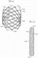
Fig. 7A-7B illustrate a sixth exemplary tool for cutting leaflets in a first contracted state and a second expanded state, respectively, according to one or more embodiments of the disclosed subject matter.
Fig. 7C-7D are simplified close-up side views of a positioning stage and a severing stage, respectively, when severing leaflets of an existing valve structure using the sixth tool of fig. 7A-7B.
Fig. 7E is a close-up side view showing an exemplary interaction between a cutting element and a positioning element of the sixth tool of fig. 7A-7B during cutting.
Fig. 7F-7G illustrate exemplary cross-sectional geometries of the cutting element of the sixth tool of fig. 7A-7B.
Fig. 7H-7I are simplified views from the ascending aorta of a positioning stage and a cutting stage, respectively, when cutting a plurality of leaflets of an existing valve structure simultaneously using a variation of a sixth exemplary tool for cutting leaflets, according to one or more embodiments of the disclosed subject matter.
Fig. 7J, 7K, and 7M are close-up side views showing alternative configurations of the cutting and positioning element of the sixth exemplary tool of fig. 7A-7I.
Fig. 7L is a close-up cross-sectional view showing an exemplary snap-fit feature of the cutting and positioning element of the sixth exemplary tool of fig. 7A-7I.
Fig. 8A is a simplified close-up side view of a positioning stage when cutting leaflets of an existing valve structure using a seventh exemplary tool having a tubular member, according to one or more embodiments of the disclosed subject matter.
Fig. 8B is a simplified side view of a variation of the seventh exemplary tool of fig. 8A having a plurality of cutting elements for cutting a plurality of leaflets.
Fig. 9A-9B are a side view and a perspective view, respectively, of an eighth exemplary tool for cutting leaflets according to one or more embodiments of the disclosed subject matter.
Fig. 9C and 9E are simplified side views of a positioning stage and a cutting stage, respectively, when using the eighth tool of fig. 9A-9B to cut leaflets of an existing valve structure.
Fig. 9D and 9F are views of the positioning and cutting stages of fig. 9C and 9E, respectively, as viewed from the ascending aorta.
Fig. 10A is a side view of a ninth exemplary tool for cutting leaflets according to one or more embodiments of the disclosed subject matter.
Fig. 10B-10C are cross-sectional views of the ninth tool of fig. 10A in a stored (stowed) configuration and a deployed configuration, respectively.
Fig. 10D-10F are perspective cross-sectional views of the ninth tool of fig. 10A during a positioning stage when cutting leaflets of an existing valve structure.
Fig. 10G is a perspective cross-sectional view of the ninth tool of fig. 10A during a puncturing stage when cutting leaflets of an existing valve structure.
Fig. 10H is a perspective, cross-sectional view of the ninth tool of fig. 10A during a cutting stage when cutting leaflets of an existing valve structure.
Fig. 10I shows the existing valve structure viewed from the ascending aorta after cutting with the ninth tool of fig. 10A.
Fig. 10J is a perspective cross-sectional view of the ninth tool of fig. 10A during a retraction stage after cutting leaflets of the existing valve structure.
Fig. 11A-11B are simplified cross-sectional views of a positioning stage and a puncturing stage when using a tenth exemplary tool to cut leaflets of an existing valve structure, in accordance with one or more embodiments of the disclosed subject matter.
Figure 11D is a close-up cross-sectional view of an alternative configuration of a tenth exemplary tool piercing member for cutting leaflets of an existing valve structure.
Fig. 11C and 11E illustrate close-up cross-sectional views of alternative configurations of a tenth exemplary tool delivery shaft tip for cutting leaflets of an existing valve structure.
Fig. 12A-12C are simplified cross-sectional views of a positioning stage, a clamping stage, and a cutting stage when using an eleventh exemplary tool to cut leaflets of an existing valve structure, according to one or more embodiments of the disclosed subject matter.
Fig. 12D is a side view of the outer shaft of an exemplary configuration of an eleventh tool.
Figures 12E-12F are first and second side views of an inner shaft of an exemplary configuration of an eleventh tool.
Fig. 12G is an assembled inner and outer shaft side view of the exemplary configuration of fig. 12D-12F positioned for use in a clamping stage.
Fig. 12H is an assembled inner and outer axial side view of the exemplary configuration of fig. 12D-12F, positioned for use in a cutting stage.
Fig. 12I is a side view of a cutting shaft of another example configuration of an eleventh tool.
12J-12M are side views of assembled inner, outer and cutting shafts of the eleventh tool configuration of FIG. 12I positioned for use in a positioning stage, a clamping stage, a cutting shaft actuation stage and a cutting stage, respectively.
Fig. 13A is a simplified cross-sectional view of a twelfth exemplary tool for cutting leaflets of an existing valve structure, according to one or more embodiments of the disclosed subject matter.
Figure 13B is a simplified cross-sectional view of a variation of a twelfth exemplary tool for cutting leaflets of an existing valve structure.
Fig. 13C and 13D-13E are simplified side and top-down cross-sectional views of another variation of a twelfth exemplary tool for cutting leaflets of an existing valve structure.
Fig. 14A is a perspective view of a thirteenth exemplary tool for cutting leaflets of an existing valve structure, according to one or more embodiments of the disclosed subject matter.
Fig. 14B-14C illustrate simplified cross-sections at different locations along the thirteenth tool of fig. 14A.
Fig. 14D is a perspective view of the thirteenth tool of fig. 14A positioned for use in a leaflet positioning stage.
Fig. 14E-14F are perspective and close-up views, respectively, of the thirteenth tool of fig. 14A positioned for use with the first cutting stage.
Fig. 14G is a perspective view of the thirteenth tool of fig. 14A positioned for pulling the leaflet for further dissection.
Fig. 15A is a perspective view of a delivery assembly of a mechanically expandable prosthetic heart valve according to one or more embodiments of the disclosed subject matter.
Fig. 15B is a perspective view of the prosthetic heart valve of fig. 15A.
Fig. 15C is a perspective view of the prosthetic heart valve of fig. 15A, without the valve structure and with the frame of the valve in a radially expanded configuration.
Fig. 15D is a side view of the prosthetic heart valve of fig. 15A in a radially compressed configuration.
Fig. 15E-15F are detailed and cross-sectional views, respectively, of an actuation mechanism of the prosthetic heart valve of fig. 15A.
Fig. 16A-16C depict stages of an exemplary implantation procedure in which a prosthetic valve is partially expanded within a subject's native aortic valve.
Fig. 16D is a detailed view of an exemplary leaflet rupture stage during partial valve expansion.
Fig. 16E-16F depict other stages of an exemplary implantation procedure after leaflet rupture.
Fig. 17A-17C are simplified side views, respectively, of a positioning stage, an advancing stage, and a cutting stage, when using a fourteenth exemplary tool to cut leaflets of an existing valve structure, according to one or more embodiments of the disclosed subject matter.
Fig. 18A-18B are simplified views of the native normal aortic valve from the ascending aorta before and after a laceration, respectively.
Fig. 19A-19B are simplified views of a native bileaflet aortic valve viewed from the ascending aorta before and after a cleavage, respectively.
Fig. 20A is a simplified cross-sectional view of a fifteenth exemplary tool for cutting leaflets of an existing valve structure, according to one or more embodiments of the disclosed subject matter.
Fig. 20B-20E are simplified side views of a leaflet of a native valve structure being cut using a fifteenth tool, a positioning stage, an advancing stage, a cutting stage, and a withdrawing stage, respectively, in accordance with one or more embodiments of the disclosed subject matter.
Fig. 21A-21B are simplified side views, in a cutting phase and a withdrawal phase, respectively, of leaflets of a previously implanted prosthetic heart valve using a fifteenth tool, according to one or more embodiments of the disclosed subject matter.
Fig. 22A-22B are exploded and assembled views, respectively, of a sixteenth exemplary tool for cutting leaflets of an existing valve structure, according to one or more embodiments of the disclosed subject matter.
Fig. 23A-23B, 23D, and 23F are side views of a leaflet of an existing valve structure being cut using a sixteenth tool, a positioning stage, a coaptation stage, a cutting stage, and a withdrawal stage, respectively, according to one or more embodiments of the disclosed subject matter.
Fig. 23C and 23E are enlarged cross-sectional views of the junction of fig. 23B and the cut of fig. 23D, respectively.
Detailed Description
General considerations
For the purposes of this description, certain aspects, advantages, and novel features of examples of the disclosure are described herein. The disclosed methods, apparatus, and systems should not be construed as limiting in any way. Instead, the present disclosure is directed to all novel and nonobvious features and aspects of the various disclosed examples, alone and in various combinations and subcombinations with one another. The methods, apparatus and systems are not limited to any specific aspect or feature or combination thereof, nor do the disclosed embodiments require that any one or more specific advantages be present or problems be solved. Techniques from any example may be combined with techniques described in any one or more other examples.
Although the operations of some of the disclosed embodiments are described in a particular, sequential order for convenient presentation, it should be understood that this manner of description encompasses rearrangement, unless a particular order is required by specific language set forth below. For example, operations described subsequently may, in some cases, be rearranged or performed concurrently. Moreover, for the sake of brevity, the attached figures may not show the various ways in which the disclosed methods can be applied in combination with other methods. Moreover, the description sometimes uses terms like "providing" or "implementing" to describe the disclosed methods. These terms are a high degree of abstraction of the actual operations performed. The actual operations that correspond to these terms may vary from implementation to implementation and can be readily identified by one of ordinary skill in the art.
As used herein with respect to prosthetic heart valve assemblies and implants and structures of prosthetic heart valves, "proximal" refers to a location, direction, or portion of a component that is closer to a user and a handle of a delivery system or device that is external to a subject, while "distal" refers to a location, direction, or portion of a component that is further from the user and the handle and closer to the site of implantation. Unless otherwise specifically defined, the terms "longitudinal" and "axial" refer to an axis extending in the proximal and distal directions.
The terms "axial direction," "radial direction," and "circumferential direction" are used herein to describe the placement and assembly of components relative to the prosthetic heart valve frame geometry. Such terms are used for convenience of description, but the disclosed embodiments are not strictly limited to this description. Specifically, when a component or action is described with respect to a particular direction, directions parallel to the specified direction and minor deviations therefrom are included. Thus, the description of the components extending in the axial direction of the frame does not require that the components be aligned with the center of the frame; rather, the component may extend substantially in a direction parallel to the central axis of the frame.
As used herein, the terms "integrally formed" and "unitary construction" refer to constructions that do not include any welds (webds), fasteners, or other means for securing the separately formed pieces of material to one another.
As used herein, operations that occur "simultaneously" or "in parallel" are generally occurring at the same time as one another, but in the absence of a specific opposite language, the delay caused by, for example, spacing between components resulting in an operation relative to the occurrence of other operations is also expressly within the scope of the above terminology.
As used in this application and in the claims, the singular forms "a", "an" and "the" include the plural forms unless the context clearly dictates otherwise. In addition, the term "comprising" means "including". Furthermore, the term "coupled" generally means physically, mechanically, chemically, magnetically, and/or electrically coupled or connected and does not exclude the presence of intervening elements between the coupled or associated items in the absence of a particular contrary language. As used herein, "and/or" means "and" or "and" or ".
Orientation and other relative references may be used to facilitate discussion of the drawings and principles herein, but are not intended to be limiting. For example, certain terms such as "inner", "outer", "upper", "lower", "inner", "outer", "top", "bottom", "inner", "outer", "left", "right", and the like may be used. Where applicable, such terms are used to provide some clear description when dealing with relative relationships, particularly with respect to the examples shown. However, these terms are not intended to imply absolute relationships, positions, and/or orientations. For example, with respect to an object, an "upper" portion may become a "lower" portion simply by turning the object over. Nevertheless, it is still the same part, while the object remains unchanged.
Examples of the disclosed technology
Tools and methods for implanting a prosthetic heart valve and modifying leaflets of an existing valve structure in a subject are described herein. Each tool may be provided in the subject's ascending aorta (or equivalent) before or during implantation of the prosthetic heart valve within the existing valve structure, and may be used to puncture, sever, scratch, tear, cut, or otherwise modify leaflets or commissures of the existing valve structure. In some embodiments, the existing valve structure can be a native aortic valve (e.g., normal or abnormal, such as a Bilobal Aortic Valve (BAV)) or a prosthetic heart valve previously implanted in a native aortic valve. The modification can avoid, or at least reduce, the likelihood that leaflets of existing valve structures can cause problems after the prosthetic heart valve is fully installed, for example, non-circular valve cross-sections that result in blocked and/or improperly installed blood flow to the coronary arteries. In other embodiments, the existing valve structure may be one of other native heart valves (e.g., a pulmonary, tricuspid, or mitral valve) or a prosthetic heart valve previously implanted therein.
In various embodiments described herein, the tools and methods may be deployed or executed within an object. Subjects include, but are not limited to, medical patients, veterinary patients, animal models, cadavers, and mimics of the heart and vasculature (e.g., anthropomorphic ghosts and transplanted tissues). Accordingly, various embodiments relate to methods for medical procedures, practices of medical procedures, and/or training of medical procedures. The mimetic may comprise all or part of the vasculature, all or part of the heart and/or all or part of a component of the vasculature (e.g., all or part of the ascending aorta). Natural tissue and/or components refer to the original tissue and/or components of a patient, animal model, cadaver, or mimetic.
Fig. 1A-1B show an exemplary prosthetic heart valve 10 according to one or more embodiments of the disclosed subject matter. The prosthetic heart valve 10 can be radially compressible/expandable between a compressed configuration for delivery into a subject and an expanded configuration for installation (e.g., as shown in fig. 1A). In particular embodiments, the prosthetic heart valve 10 can be implanted within the native aortic annulus 18.
The prosthetic heart valve 10 can include an annular stent or frame 12. The frame 12 or components thereof (e.g., struts and/or fasteners) may be made of various suitable plastically-expandable materials (e.g., stainless steel, etc.) or self-expanding materials known in the artA material (e.g., nickel titanium alloy (NiTi) such as nitinol), etc. Suitable plastically-expandable materials that may be used to form frame 12 include, without limitation, stainless steel, biocompatible high-strength alloys (e.g., cobalt-chromium alloys or nickel-cobalt-chromium alloys), polymers, or combinations thereof. In particular embodiments, frame 12 is formed from a nickel-cobalt-chromium-molybdenum alloy such as Alloy (SPS Technologies, jenkingtown, pennsylvania), which is equivalent to UNS R30035 alloy (covered by ASTM F562-02), was made.
 The alloy/UNS R30035 alloy comprises, by weight, 35% nickel, 35% cobalt, 20% chromium and 10% molybdenum.
When made of a plastically-expandable material, the frame 12 (and thus the prosthetic valve 10) can be crimped (crimped) onto a delivery catheter into a radially-crimped configuration, and then expanded within a subject by an inflatable balloon or equivalent expansion mechanism. When constructed of a self-expandable material, the frame 12 (and thus the prosthetic valve 10) can be crimped into a radially collapsed configuration and restrained in the collapsed configuration by insertion of a sheath of a delivery catheter or equivalent mechanism. After being in the body, the prosthetic valve can be advanced from the delivery sheath, which allows the prosthetic valve to expand to its functional size.
In some embodiments, the struts of the frame 12 are pivotable or bendable relative to each other, allowing the frame 12 to radially expand and contract. For example, the frame 12 may be formed from a single piece of material (e.g., a metal tube) (e.g., via laser cutting, electroforming, or physical vapor deposition). In other embodiments, the frame 12 may be constructed by forming separate components (e.g., posts and fasteners of the frame) and then mechanically assembling and connecting the separate components together. Further details regarding the construction of the frame 12 and prosthetic heart valve 10 are described in U.S. patent nos. 9,393,110, 10,603,165, and 10,806,573, U.S. patent application publication nos. 2018/0344456, 2019/0365530, 2020/0188099, and 2020/0390547, and international publication nos. WO/2020/081893 and WO/2021/003,167, all of which are incorporated herein by reference.
The frame 12 may have a first axial end and a second axial end. In the depicted embodiment, the first axial end (e.g., facing the ascending aorta 20 near the sinotubular junction level 32) may be the outflow end, while the second axial end (e.g., facing the left ventricle 26 near the aortic root 18) may be the inflow end. In some embodiments, the outflow end can be coupled to a delivery apparatus for delivering the prosthetic valve to an implantation site. Alternatively, the prosthetic valve 10 can be radially crimped over an inflatable balloon of a delivery device for delivery to the implantation site. Implantation of the prosthetic heart valve 10 within the native aortic valve can be via a transfemoral retrograde delivery approach. Thus, in the delivery configuration of the prosthetic heart valve, the outflow end is the most proximal end of the prosthetic valve. In other embodiments, the inflow end may be the proximal-most end of the prosthetic heart valve in a delivery configuration, depending on the particular native valve being replaced and the delivery technique being used (e.g., transseptal, transapical, etc.). In some cases, the inflow end can be coupled to a delivery apparatus in a delivery configuration.
The prosthetic valve 10 also includes a valve structure configured to allow blood to flow in one direction through the frame 12. The valve structure can be configured to regulate the flow of blood through the prosthetic heart valve 10 from the inflow end to the outflow end. The valve structure can include, for example, a valve leaflet assembly formed of one or more leaflets 14 (three leaflets illustrated in fig. 1A-1B) made of a flexible material. Adjacent leaflets 14 can be disposed together to form commissures 36, the commissures 36 being coupled (directly or indirectly) to respective portions of the frame 12 to thereby secure at least portions of the leaflet assembly to the frame 12. The leaflets 14 can be made, in whole or in part, of a biomaterial, a biocompatible synthetic material, or other such material. Suitable biological materials may include, for example, bovine pericardium (or pericardium from other sources). Additional details regarding transcatheter prosthetic heart valves, including the manner in which valve structures may be coupled to the frame 12 of the prosthetic heart valve 10, may be found in U.S. patent nos. 6,730,118, 7,393,360, 7,510,575, 7,993,394, 8,652,202, and 9,393,110, and U.S. patent application publication nos. 2018/0325665 and 2019/0365530, the entire contents of which are incorporated herein by reference.
The prosthetic heart valve 10 can also include one or more skirts or sealing members. For example, the prosthetic heart valve 10 can include an inner skirt mounted on an inner surface (not shown in fig. 1A-1B) of the frame 12 and/or an outer skirt 16 mounted on an outer surface of the frame 12. The inner skirt may be a circumferential inner skirt that spans the entire circumference of the inner surface of the frame 12. The inner skirt may act as a sealing member to prevent reduction of valve paravalvular leakage (e.g., when the valve is placed at the implantation site), and as an attachment surface to anchor a portion of the leaflets 14 to the frame 12. The outer skirt 16 can act as a sealing member by sealing against the tissue of the native annulus 18 and helping to reduce paravalvular leakage past the prosthetic valve 10. The inner and outer skirts may be formed of any of a variety of suitable biocompatible materials, including any of a variety of synthetic materials (e.g., polyethylene terephthalate (PET)) or natural tissue (e.g., pericardial tissue). The inner and outer skirts may be mounted to the frame using stitches, adhesives, welding, and/or other means for attaching the skirt to the frame. Additional details regarding the inner and outer skirt techniques of assembling leaflets to the inner skirt and skirt to the frame are disclosed in U.S. patent No. 9,393,110, U.S. patent application publication nos. 2019/0192296 and 2019/0365530, and international publication nos. WO/2020/198273 and WO/020/159783, all of which are incorporated herein by reference.
In the description of the disclosed embodiments, the methods and devices are described in the context of employing a retrograde delivery approach to the native aortic valve. Thus, the term "proximal" of a prosthetic valve (or other device) or component thereof is used to refer to its outflow end, while the term "distal" of a prosthetic valve (or other device) or component thereof is used to refer to its inflow end. It should be noted, however, that if delivered in the opposite direction to the aortic valve (e.g., transapical), the outflow end of the prosthetic valve will be distal and the inflow end of the prosthetic valve will be proximal during delivery. Thus, in the present application, the term "proximal" means the "outflow end" and the term "distal" means the "inflow end" after implantation of the prosthetic valve at the aortic site. Similarly, the terms "distal" and "distal" as used herein to describe a component or portion of an anatomical structure mean "upstream" and "upstream", while the terms "proximal" and "proximal" as used herein to describe a component or portion of an anatomical structure mean "downstream" and "downstream". Furthermore, any of the methods and devices described herein may be applicable to any native valve of the heart (aortic, mitral, tricuspid, and pulmonic) or prosthetic valve previously implanted within any native valve of the heart using any known technique, which may involve accessing the native valve in a retrograde or anterograde direction.
With existing implanted prosthetic valves, the valve structure may naturally degrade over time, thus requiring repair or replacement to maintain adequate cardiac function. In a valve-in-valve (ViV) procedure, a new prosthetic heart valve is installed within an existing, degenerated prosthetic heart valve to restore normal function. However, the ViV procedure may increase the risk of occlusion of the coronary arteries 22, 24. Specifically, installing a new prosthetic heart valve within the valve structure of an existing prosthetic heart valve may displace the leaflets of the existing heart valve outward, thereby occluding the ostia of the coronary arteries 22 and 24. Furthermore, because the leaflets of existing heart valves are disposed outside of the frame of the new prosthetic valve, they may cover the outer surface of the frame, creating a tubular structure that is relatively impermeable, occluding the opening 34 in the frame 12. In certain subject anatomies (e.g., when the outflow portion of the valve 10 is at the sinotubular junction (STJ) level 32 and the diameter of the valve 10 is similar to the STJ diameter such that the frame 12 contacts or is in close proximity to the aortic wall 30 at the STJ level 32), the leaflets of the existing valve structure may impair the ability to enter the coronary arteries 22, 24 in the future or to perfuse the coronary arteries 22 and 24 through the valve frame 12 during the diastolic phase of the cardiac cycle. Similar problems may arise in certain subject anatomies when the prosthetic heart valve 10 is percutaneously expanded within the native valve, thereby displacing the native leaflets 38 outward toward the coronary ostia.
To avoid blockage of blood flow to the coronary arteries 22, 24, the valve structure of the existing heart valve (whether a native aortic valve or a previously implanted prosthetic valve) may be modified by tools prior to or during implantation of the new prosthetic heart valve within the existing valve structure. In embodiments, the valve structure is modified by using a tool to puncture, sever, tear, lacerate, and/or cut one or more leaflets 14 (e.g., free ends of the leaflets 14 or commissures 36 in adjacent leaflets 14). Thus, the modification disrupts the impermeable tubular structure that would otherwise be formed by the existing leaflets 14, allowing blood to flow to the coronary arteries 22, 24. Alternatively or additionally, when the existing valve structure is a BAV, the modification may allow for improved installation of a cylindrical prosthetic valve that would otherwise be compromised by the non-circular geometry of the native BAV.
For example, fig. 2A illustrates a first exemplary tool 100 that can be used to cut leaflets 14 of an existing valve structure. The tool 100 includes a catheter 102, the catheter 102 having a distal end 104 configured to be disposed within the ascending aorta of a subject. The catheter 102 includes at least three components therein-a first spacing member 106, a second spacing member 108, and a cleavage member 110. Each of the members 106-110 is independently steerable within the catheter 102 and extends from the catheter 102, for example, by an operator manipulating a handle (not shown) at a proximal region of the catheter 102. The catheter 102 in the illustrated embodiment is in the form of a shaft, but in other embodiments described below, the catheter may include multiple shafts that may be coaxially arranged relative to one another.
Each of the members 106-110 may extend from the tip 104 of the catheter 102 to interact with existing valve structures. For example, as shown in fig. 2B-2D, the first positioning member 106 can be configured for insertion into a pocket 112 between the leaflets 14 and the frame 12 (or aortic wall 30 — when dealing with a native valve) of an existing valve structure to provide sufficient spacing for subsequent positioning of the rupture member 110. Second spacer member 108 may be configured to push against the opposite side of frame 12 (or aortic wall 30 — when treating a native valve) to enhance circumferential positioning and alignment of first positioning member 106 and cleavage member 110 during dissection of leaflets 14.
Each of the members 106-110 may be a pre-shaped wire, for example, a wire formed from a shape memory alloy such as nitinol. Thus, as the members 106-110 are pushed out of the tip 104 of the catheter 102, the ends thereof may assume their predetermined shape. For example, the first positioning member 106 may have a contoured end (contoured end) that is circular, oval (e.g., spoon-shaped), elliptical, or any other shape to increase the area of the first positioning member 104 that contacts the downstream side of the leaflet 14. In some embodiments, the first positioning member 106 may be formed from a plurality of wires, e.g., a pair of wires 106a, 106b formed to laterally curve to converge (converge) to contact or attach to each other at the distal tip 106 c. The second spacing member 108 may be curved or curved along its length to urge a structure (e.g., a valve frame or aortic wall) opposite the first positioning member 106. The fracturing member 110 may be bent at its end, for example, to form a hook shape.
Fig. 2B-2D show various stages of using the first exemplary tool 100 to modify the leaflets 14 of an existing valve structure to avoid occlusion of the coronary arteries by a subsequently implanted prosthetic heart valve. The catheter shaft 102 may be advanced from the ascending aorta to the existing valve structure. The first positioning member 106, the second positioning member 108, and the fracturing member 110 can be retained within the catheter 102 prior to reaching the valve 10. After the catheter 102 reaches the valve 10 (e.g., the distal end 104 is positioned near the valve 10), the first positioning member 106 can be pushed out of the catheter 102 into a pocket 112 formed between the leaflets 14 and the frame 12 of the existing valve 10. For example, the first positioning member 106 can be advanced, e.g., along the fan line, until the leaflet 14 is attached (e.g., in contact) with the distal end 12a of the frame 12, as shown in fig. 2B.
After or while pushing the first positioning member 106 out of the catheter 102, the second positioning member 108 may be pushed out of the catheter 102. As described above, the second positioning member 108 may be curved to deflect radially outward away from the first positioning member 106 after it exits the catheter 102, thereby pressing against the side of the frame 12 opposite the first positioning member 106, as shown in fig. 2A. Thus, the second locating member 108 serves to align the position of the first locating member 106 and to hold the member 106 in place during a subsequent fracturing procedure.
With the first and second positioning members 106, 108 in place within the valve 10, the fracturing member 110 can then be pushed out of the catheter 102 toward the space formed between the free ends of the leaflets 14 and the frame 12 of the valve 10. As described above, after the fracturing member 110 extends from the tip 104 of the catheter 102, it may be bent at its end to assume a J-shape or hook shape. Thus, the first positioning member 106 enlarges the gap between the proximal end (e.g., free end) of the leaflet 14 and the frame 12 to facilitate positioning the curved end of the fracturing member 110 on the downstream side of the leaflet 14.
The ends of the fracturing member 110 can be relatively hard (e.g., harder than other portions of the fracturing member 110 and/or other members 106-108) and/or have sharp tips such that the fracturing member 110 pierces the leaflets 14 at 114, as shown in fig. 2C. Alternatively or additionally, the fracturing member 110 is configured to cut or fracture tissue of the leaflets 14 by applying electrical energy (e.g., radio Frequency (RF) energy) at the ends of the fracturing member 110. For example, electrical energy can be applied to a distal or intermediate portion of the fracturing member 110 that contacts the leaflet 14 such that the fracturing member 110 penetrates the leaflet 14 at 114, as shown in fig. 2C. The rupture member 110 can then be moved proximally away from the valve 10, as shown in fig. 2D, for example, while optionally applying electrical energy thereto to form a tear 116 that flares the leaflets 14 outward into the individual portions 14a-14b, as shown in fig. 2E. For example, proximal movement of the fracturing member 110 may be performed by: retracting the fracturing member 110 into the catheter 102 while maintaining the catheter 102 and/or the members 106-108 in the resting position, retracting all of the members 106-110 into the catheter 102 while maintaining the catheter 102 in the resting state, retracting the catheter 102 in a proximal direction while maintaining the position of the members 106-110 relative to the distal end 104, or any other combination of movement of the members 106-100 and the catheter 102.
If additional dissection of one or more leaflets 14 of an existing valve structure is required, for example to provide an opening for a coronary artery 22, 24, the catheter 102 can be repositioned (e.g., rotated) relative to the next leaflet after the members 106-110 are partially or fully retracted into the catheter 102. The dissection of the next leaflet 14 can then be performed in a similar manner as described above with respect to fig. 2B-2E. When no further cutting is required, the members 106-110 can be fully retracted and the catheter 102 withdrawn from the subject. As part of the ViV procedure, the new prosthetic heart valve in the crimped state can then be advanced to the existing valve structure with the leaflets 14 cut. The new valve is disposed within the valve structure and expanded such that the leaflets 14 are disposed on the outer surface of the new valve frame. However, after completion of the ViV procedure, one or more tears 116 formed in the leaflets 14 allow blood to flow from the outflow end of the new prosthetic valve to the coronary arteries 22, 24. Alternatively or additionally, when the existing valve structure is a BAV, the one or more splits formed in the leaflets may allow for improved installation of a cylindrical prosthetic valve that would otherwise be compromised by the non-circular geometry of the native BAV.
In some cases, the plurality of leaflets 14 of the existing valve structure (e.g., two of the three leaflets of the aortic valve) may need to be modified to allow sufficient blood flow to reach the two coronary arteries after implantation of the new prosthetic valve. Since the components 106-110 of the first tool 100 may be manipulated independently of one another, subsequent modifications to another leaflet may require independent retrieval and repositioning of each component 106-100, which may be tedious and/or time consuming. In some embodiments, the positioning member can be used to simultaneously reposition the members 106-110 to modify the next leaflet, for example, by simply rotating the members 106-100 relative to the existing valve structure while maintaining the relative position between the members 106-110.
For example, fig. 3A-3B illustrate a second exemplary tool 200 that can be used to sequentially cut a plurality of leaflets 14 of an existing valve structure. The second tool 200 may have a first positioning member 106, a second spacing member 108, and a cleaving member 110, and may operate in a similar manner as the first tool 100 described above with respect to fig. 2A-2E. However, the second tool 200 may also have a multichannel positioning member 206 disposed at the distal end of the catheter 202. The multi-channel positioning component 206 may have channels 210, 208, and 212 through which the first positioning member 106, the second spacing member 108, and the cleaving member 110 extend, respectively. Positioning member 206 can be rotated about the axis of catheter 202 such that the respective outlets of channels 208-212 are reoriented relative to another leaflet of the existing valve structure for cutting. The positioning member 206 may have a shape that facilitates insertion into and movement through a blood vessel of a subject. For example, the positioning member 206 may have a tapered or tapered shape (e.g., nose-tapered) that narrows from its proximal end to its distal end, as shown in fig. 3A-3B.
The channels 208-212 may be formed to maintain a desired relative positioning between the first positioning member 106, the second spacing member 108, and the fracturing member 110 during the cutting of the leaflets and during rotation of the positioning member 206. For example, each of the channels 208-212 may be angled with respect to the longitudinal axis of the conduit 202. In some embodiments, the distal opening of the channel 208 of the second spacer member 108 is located at a circumferential position on the positioning member 206 opposite the distal opening of the channel 210 of the first positioning member 106. The distal opening of the channel 212 of the fracturing member 110 may be positioned adjacent to the distal opening of the channel 210 of the first spacing member or at a circumferential location on the positioning member 206 between the openings of the channels 208 and 210, as shown in fig. 3A-3B. In some embodiments, the positioning member 206 may further include another channel (not shown) extending, for example, through a central portion of the positioning member 206 through which a guidewire may extend.
In some embodiments, the tool 200 has an inner shaft 204 extending therein and attached at its distal end to the proximal end of a positioning member 206, as shown in fig. 3A. The inner shaft 204 may be coaxial with the catheter 202 and may be movable (e.g., rotatable) independently of the catheter 202 (which may be referred to as the outer shaft of the tool in some embodiments). The members 106-110 can extend through the lumen of the inner shaft to the respective channels 208-210 of the positioning member. The attachment of the inner shaft 204 to the positioning member 206 thus allows the positioning member 206 to be rotated at the end of the catheter 202 by rotating the inner shaft 204 at its proximal end (e.g., by rotating the shaft 204 directly or via a handle at its proximal end). Optionally, the inner shaft 204 may be omitted, which facilitates attachment of the positioning member 206 to the distal end of the catheter 202, whereby rotation of the positioning member 206 relative to the existing valve structure is achieved by rotating the entire catheter 202 (e.g., by rotating the catheter 202 directly or via a handle at its proximal end). Because at least portions of the members 106-110 are retained within their respective channels 208-212, their position relative to each other is maintained throughout the rotational movement of the positioning member 206. Thus, the second tool 200 allows the members 106-110 to be repositioned circumferentially to perform the cutting process on another leaflet 14 by simply rotating only a single component, such as the positioning member 206, rather than requiring each of the members 106-100 to be independently positioned as in the first tool 100.
In some cases, it may be desirable to sever one or more commissures 36 of an existing valve structure, rather than modifying an unattached portion (e.g., middle region or free end) of the leaflet 14, or it may be desirable to sever one or more commissures 36 of an existing valve structure in addition to modifying an unattached portion (e.g., middle region or free end) of the leaflet 14. By cutting the commissures 36, the leaflets 14 of the existing valve structure can collapse distally (e.g., toward the left ventricle 26) (collapse). With the leaflets 14 in the collapsed orientation, the coronary ostia are occluded, allowing blood to flow toward the coronary arteries 22, 24 after the new prosthetic valve is installed within the existing valve structure.
For example, fig. 4A-4E illustrate a third example tool 300 that may be used to cut the commissures 36 of the valve structure of an existing heart valve (whether a native aortic valve or a previously implanted prosthetic valve). The tool 300 includes a catheter 302 (which may also be referred to as a shaft of the tool in some embodiments), where the distal end is configured to be disposed within the ascending aorta of the subject. A substantially cylindrical head 304 may be disposed at the distal end of the catheter 302. The head 304 may have a structure that grips and cuts the commissures 36. For example, the head 304 may have a first recess 310 extending in an axial direction of the head, as shown in FIG. 4B. The first recess 310 may be defined by axially extending edges 316 (e.g., portions of the circumferential wall of the head) of the first and second arms 312a, 312 b. The first recess 310 may be U-shaped with a curvilinear proximal edge (e.g., as shown in fig. 4B), have a substantially rectangular shape (e.g., similar to recess 314 in fig. 4C), or have any other shape (e.g., a-shaped as in fig. 4F, wherein the head 324 has a recess 330 defined between edges 336 of arms 332a, 332B, the recess 330 narrowing in the proximal direction to the cutting region 328). The opening at the distal end of the recess 310 may be sized to accommodate the thickness of the commissures 36 between the edges 316 (e.g., twice the thickness of a single leaflet). At the proximal end of the first recess 310, the head 304 may include a mechanical cutting element 308, e.g., a sharp edge or blade, the shape of which may correspond to the shape of the recess (e.g., straight or arcuate). Alternatively or additionally, the cutting element 308 may be configured to cut tissue of the commissure 36 in contact therewith by applying electrical energy (e.g., RF energy). For example, the cutting element 308 may be a non-insulated portion of the head 304.
The head 304 may have a structure that passively grips or abuts the commissure 36 before or during cutting of the commissure 36 by the cutting element of the first recess 310. For example, the head 304 may have a second recess 314 on a side of the head 304 opposite the first recess 310, as shown in fig. 4C-4D. The second recess 314 may also be defined by axially extending edges of the first and second arms 312a, 312 b. The second recess 314 may be similar in size and shape to the first recess 310 or different from the first recess 310. For example, the second recess 314 may extend longer in the axial direction than the first recess 310. The second recess 314 may be U-shaped with a curvilinear proximal edge (e.g., similar to the recess 310 in fig. 4B), have a substantially rectangular shape (e.g., as shown in fig. 4C), or have any other shape (e.g., as an a-shape in fig. 4F, where the head 324 has a recess 330 defined between edges 336 of the arms 332a, 332B, the recess 330 narrowing in the proximal direction). The opening at the distal end of the recess 314 may be sized to accommodate the thickness of the commissures 36 between the edges of the arms 312a, 312 b. Alternatively or additionally, the head 304 may have a structure that actively grips the commissures 36, such as by a gripping mechanism.
Referring to fig. 4A and 4E, a third tool 300 is shown in various stages for cutting the commissures 36 of the existing valve structure to avoid occlusion of the coronary arteries by a subsequently implanted prosthetic heart valve. The catheter shaft 302 may be advanced from the ascending aorta to an existing valve structure (e.g., the previously implanted valve 10 in fig. 4A). In some embodiments, the guidewire 306 can extend through the lumen of the catheter 302 toward the existing valve 10 to align the head 304 with the commissures 36 to be cut. Specifically, the alignment may utilize the tendency of the guidewire 306 to direct itself to the point of least energy, moving toward the commissures 36 rather than the mid-region of the leaflets 14. The commissures 36 thus act as receiving notches for the spring-like tensioned wire 306. The guidewire 306 may extend through the center of the commissures (e.g., between facing surfaces of adjacent leaflets 14).
The catheter 302 is then advanced over the guidewire 306 such that the commissures 36 are received within the recesses 310, 314 of the head 304, as shown in fig. 4E. In some embodiments, the cutting recesses 310 can be disposed radially outward of the head 304 facing the frame 12 of the valve 10, while the clamping recesses 314 can be disposed radially inward of the head 304 facing the center of the frame 12. In other embodiments, the positions of the cutting recess 310 and the clamping recess 314 may be reversed, with the clamping recess 314 being between the cutting recess 310 and the frame 12 in the radial direction. In either case, as the head 304 is advanced in the distal direction, the proximal edge of the commissures 36 moves into contact with the cutting elements 308 of the recesses 310, the cutting elements 308 then lacerate the commissures 36 using mechanical (e.g., sharp edges or blades) or electrical (e.g., RF energy applied to non-insulated portions at the proximal end of the recesses 310) means.
If other commissures 36 of the existing valve structure are to be cut, the third tool 300, along with the guide wire 306, can be retracted and repositioned relative to the adjacent commissures. The cutting of the head 304 may then be repeated for adjacent commissures in a manner similar to that described above. For example, when the existing valve structure has three leaflets 14 and three commissures 36, the head 304 can be used to cut at least two of the three commissures to allow the leaflets of the existing valve structure to collapse distally out of the way of the coronary ostia.
As part of the ViV procedure, the new prosthetic heart valve in the crimped state can then be advanced to the existing valve structure with collapsed leaflets 14. The new valve is deployed within the valve structure and expanded. However, the collapsed leaflets are disposed distal of the prosthetic heart valve, allowing unobstructed flow of blood from the outflow end of the new prosthetic valve to the coronary arteries 22, 24 after completion of the ViV procedure. Alternatively or additionally, when the existing valve structure is a BAV, the collapsed leaflets can allow for improved installation of a cylindrical prosthetic valve that would otherwise be compromised by the non-circular geometry of the native BAV.
Instead of static recesses 310, 314 for cutting and passively clamping the commissures 36, the head may be provided with an active structure that moves the cutting and/or clamping commissures. For example, fig. 5A-5D illustrate a fourth example tool 400 that can be used to cut the commissures 36 of the valve structure of an existing heart valve (whether a native aortic valve or a previously implanted prosthetic valve 10). The tool 400 includes a catheter 402 (which may also be referred to as a shaft of the tool in some embodiments) whose distal end is configured to be disposed within the ascending aorta of a subject. The head 404 may be disposed at the distal end of the catheter 402. The head 404 may have an active structure that grips and cuts the commissures 36. For example, the head 404 has a first active mechanism 406 for gripping and a second active mechanism 408 for cutting. A first member 410 (e.g., a tether, suture, shaft, cable, or wire) coupled to first mechanism 406 may allow an operator to actuate first mechanism 408, for example, via a handle (not shown) at a proximal end of catheter 402. Similarly, a second member 412 (e.g., a tether, suture, shaft, cable, or wire) coupled to the second mechanism 408 can allow an operator to actuate the second mechanism, e.g., via the same or a different handle at the proximal end of the catheter 402.
The first mechanism 406 may have a first arm 406a and a second arm 406B that are movable relative to each other, as shown in fig. 5B-5C. For example, the first arm 406a and/or the second arm 406b may have respective facing edges (e.g., with serrated or toothed surfaces 416a, 416 b) that are enhanced for gripping the commissures 36. In some embodiments, the first and second arms 406a, 406b are coupled together to allow pivotal or rotational movement relative to each other (e.g., similar to a scissor mechanism). In some embodiments, second gripper arm 406b remains stationary (e.g., relative to catheter 402) while first gripper arm 402a pivots relative to second gripper arm 406b about hinge 414. For example, as shown in fig. 5C, second grasping arm 406b may be an extension of or connected to the distal end of a shaft extending through catheter 402, while first member 410 may extend through the shaft of second grasping arm 406a or alongside the shaft of second grasping arm 406 b. A first member 410 extending through the lumen of the catheter 402 and coupled to the first clamp arm 406a can be used to actuate the first clamp arm 406a about the hinge 414, such as by pulling the first member 410 proximally relative to the shaft of the second clamp arm 4026 b. Optionally, first clamp arm 406a remains stationary (e.g., relative to conduit 402) while second clamp arm 416b pivots about a hinge relative to first clamp arm 406a.
Alternatively or additionally, other elements may be included within the conduit 402 and/or in the head 404 to position the clamp arms 406a, 406b before, during, or after actuation by the operator. For example, a spring element (not shown) may be provided to urge the clamp arms 406a, 406b together in a normally closed configuration or away from each other in a normally open configuration. In another example, a protrusion or actuating stop can be disposed between the clamp arms 406a, 406b to limit the movement of the clamp arms 406a, 406b toward each other, e.g., to set a minimum gap between the arms 406a, 406b to maximize clamping without prematurely damaging the leaflets prior to being cut by the second mechanism 408.
The second mechanism 408 may have a first arm 408a and a second arm 408B that are movable relative to each other, as shown in fig. 5B and 5D. For example, the first arm 408a and/or the second arm 408b can have respective facing edges with mechanical cutting features (e.g., sharp edges or blade portions 420a, 420 b). Optionally, the first arm 408a and/or the second arm 408b can be configured to cut using electrical energy (e.g., RF energy) applied thereto (e.g., via the non-insulated edge portions 420a, 420 b). In some embodiments, the second member 412 or another member (e.g., a cable or wire) extending through the lumen of the catheter 402 may be configured to transmit electrical energy (e.g., RF energy) to the first cutting arm 408a, the second cutting arm 40b, or portions thereof to effect cutting of commissure tissue.
In some embodiments, the first arm 408a and the second arm 408b are coupled together to allow pivotal or rotational movement relative to each other (e.g., similar to a scissor mechanism). In some embodiments, the second cutting arm 408b remains stationary (e.g., relative to the catheter 402) while the first cutting arm 408 is pivoted about the hinge 418 relative to the second cutting arm 408b. For example, as shown in fig. 5D, the second cutting arm 408b may be an extension of or connected to the distal end of a shaft extending through the catheter 402, while the second member 412 may extend through or alongside the shaft of the second arm 408b. The second member 412 extending through the lumen of the catheter 402 and coupled to the first cutting arm 408a may be used to actuate the first cutting arm 408a about the hinge 418, such as by pulling the second member 422 proximally relative to the axis of the second cutting arm 408b. Optionally, the first cutting arm 408a remains stationary (e.g., relative to the catheter 402) while the second cutting arm 408b pivots about a hinge relative to the first cutting arm 408a. Alternatively or additionally, other elements may be included within the catheter 402 and/or in the head 404 to position the cutting arms 408a, 408b before, during, or after actuation by the operator. For example, a spring element (not shown) may be provided to urge the cutting arms 408a, 408b together in a normally closed configuration or away from each other in a normally open configuration.
The operation of the fourth tool 400 to cut the commissures 36 of the existing valve structure may be similar to that of the third tool 300, except that the clamping and cutting are performed by the active structure. Specifically, the catheter shaft 402 may be advanced from the ascending aorta to an existing valve structure (e.g., the previously implanted valve 10 in fig. 5A). In some embodiments, a guidewire (not shown) can extend through the lumen of the catheter 402 toward the existing valve 10 to align the head 404 with the commissures 36 to be cut. Alignment may utilize a tendency of the guidewire to direct itself to a point of minimum energy, moving toward the center of the commissures 36 (e.g., between facing surfaces of adjacent leaflets 14) rather than the middle region of the leaflets 14. The commissures 36 thus act as receiving notches for the spring-like tensioned guide wire.
The catheter 402 is then advanced over the guidewire so that the commissures 36 are received within the open recesses between the clamping arms 406a, 406b and between the cutting arms 408a, 408b, as shown in fig. 5A. For example, the first clamp arm 406a may pivot away from the second clamp arm 406b, and the first cutting arm 408a may pivot away from the second cutting arm 408 b. In some embodiments, the cutting mechanism 408 can be disposed radially outward of the head 404 facing the frame 12 of the valve 10, while the clamping mechanism 406 can be disposed radially inward of the head 404 toward the center of the frame 12. In other embodiments, the positioning of the cutting mechanism 408 and the clamping mechanism 406 may be reversed with the clamping mechanism 406 being between the cutting mechanism 408 and the frame 12 in the radial direction.
After the commissure 36 is sufficiently positioned between the clamping mechanism 406 and the cutting mechanism 408 (e.g., when the proximal end of the commissure is adjacent or abuts the proximal edge of the recess between the cutting arms 408a, 408 b), the commissure 36 can be clamped by the clamping mechanism 406, for example, by actuating the first member 410 to pivot the first clamping arm 406a toward the second clamping arm 416b, thereby clamping a portion of the commissure 36 between the surfaces 416a, 416 b. After being gripped by the mechanism 406, the commissures 36 can then be cut by the cutting mechanism 408, for example, by actuating the second member 412 to pivot the first cutting arm 408a toward the second cutting arm 4080b, thereby scoring (e.g., via a mechanical or electrical cutting device) the portion of the commissure 36 between the surfaces 420a, 420 b.
In some embodiments, the arms 408a, 408b of the cutting mechanism 408 have a length in the axial direction of the catheter 402 that is greater than the length of the arms 406a, 406b of the gripping mechanism 406. Thus, the arms 406a, 406b may be sized to grip a sufficient portion (e.g., a minimum length) of the commissures 36. The arms 408a, 408b can be sized to extend beyond the corresponding dimensions of the commissures 36 to allow for cutting of the commissures to be completed by a single closure of the recess between the arms 408a and 408b (e.g., a single shearing motion of the mechanism 408). Alternatively or additionally, actuation of the second member 412 may be repeated, for example, repeatedly opening and closing a recess between the cutting arms 408a, 408b to shear the lacerated commissures 36. In some embodiments, the clamping mechanism 406 can clamp the commissures 36 between the arms 406a, 406b until the cutting mechanism 408 completes cutting. The active clamping mechanism 406 may be used to stabilize the commissures 36 during their cutting by the cutting mechanism 408. Further, the active gripper mechanism 406 may be used to retract the portion of the commissures held between the gripper arms 406a, 406b after being cut by the cutting mechanism 408.
If other commissures 36 of the existing valve structure are to be cut, the fourth tool 400, along with the guide wire, can be retracted and repositioned relative to the adjacent commissures. The cutting of the head 404 may then be repeated for adjacent commissures in a manner similar to that described above. For example, when the existing valve structure has three leaflets 14 and three commissures 36, the head 404 can be used to cut at least two of the three commissures to allow the leaflets of the existing valve structure to collapse distally out of the way of the coronary ostia.
As part of the ViV procedure, the new prosthetic heart valve in the crimped state may then be advanced to the existing valve structure with collapsed leaflets 14. The new valve is deployed within the valve structure and expanded. However, the collapsed leaflets are disposed distal of the prosthetic heart valve, allowing unobstructed flow of blood from the outflow end of the new prosthetic valve to the coronary arteries 22, 24 after completion of the ViV procedure. Alternatively or additionally, when the existing valve structure is a BAV, the collapsed leaflets may allow for improved installation of a cylindrical prosthetic valve that would otherwise be compromised by the non-circular geometry of the native BAV.
In some cases, it may be desirable to cut multiple commissures 36 simultaneously, rather than sequentially cutting individual commissures as with the third and fourth tools 300, 400. For example, fig. 6A illustrates a fifth example tool 500 that may be used to simultaneously cut (cut through) multiple commissures 36 of a valve structure of an existing heart valve (whether a native aortic valve or a previously implanted prosthetic valve 10). The tool 500 includes a catheter 502 (which may be referred to as a shaft of the tool in some embodiments) whose distal end is configured to be disposed within the ascending aorta of a subject. The tool 500 may also include a three-dimensionally shaped flexible frame 504 configured to expand from a first size inside the catheter 502 to a second larger size outside the catheter 502 (e.g., corresponding to the diameter at which the commissures 36 are positioned relative to the existing valve structure). All or a portion of the frame 504 may be formed of a shape memory alloy, such as nitinol, to self-expand to a larger second size upon release from the distal end of the catheter 502. In this manner, the flexible framework 504 may self-expand from a delivery state to its functional size after deployment from a catheter.
Each proximal apex 512 may correspond to a respective one of the commissures 36 of the existing valve structure. For example, the number of proximal apices 512 of the frame 504 may be equal to the number of commissures 36 of the existing valve structure. Each proximal apex 512 may include a respective cutting element 514 configured to sever the commissures 36 in contact therewith. For example, the cutting element 514 may be a sharp edge of the frame or a blade attached to the frame. Optionally, the cutting element 514 may be configured to cut using electrical energy (e.g., RF energy) applied thereto. For example, the cutting element 514 may be a non-insulated metal portion of the frame or a separate member attached to the frame.
A plurality of support arms 506 may be coupled to the frame 504, for example, at a distal apex 510. The support arms 506 may be used to axially position the frame 504 relative to the catheter 502 (e.g., to move the frame 504 from within the catheter 502 to an existing valve structure, or vice versa) and/or circumferentially relative to the valve structure (e.g., to align the distal apices 510 with corresponding recesses 516 formed between adjacent commissures 36). All or a portion of each support arm 506 may also be formed from a shape memory alloy such as nitinol.
Referring to fig. 6B-6C, a fifth tool 500 is shown in an alignment stage and a cutting stage, respectively, for simultaneously cutting multiple commissures 36 of an existing valve structure to avoid occlusion of the coronary arteries by a subsequently implanted prosthetic heart valve. The catheter shaft 502 may be advanced from the ascending aorta to an existing valve structure (e.g., the previously implanted valve 10 in fig. 6B). During advancement of the catheter 502, the support arm 506 and the frame 504 may remain within the lumen of the catheter 502. Upon reaching the valve 10, the support arms 502, along with the frame 504 coupled thereto, may be pushed distally out of the lumen of the catheter shaft 502. Alternatively or additionally, the support arms 506 and frame 504 may remain in place, while the catheter shaft 502 may be retracted proximally to expose the frame 504 from the distal end of the catheter 502.
The frame 504 and/or support arms 506 can expand radially outward, increasing the diameter of the frame 504 such that the location of the proximal apex 512 is close to the inner diameter of the valve frame 12, or at least matches the radial location of the commissures 36 of the valve 10. In some embodiments, the frame 504 can be rotated about the axis of the catheter shaft 502, for example, to enable an operator to align the distal apices 510 with corresponding pockets 516 between the proximal surfaces of the leaflets 14 and the inner wall of the valve frame 12, and to align the commissures 36 with the proximal apices 512. The shape and arrangement of distal apices 510 and/or struts 508 may also urge frame 504 into alignment with commissures 36 when frame 504 is advanced into contact with the valve structure of existing valve 10.
After the frame 504 is aligned with and in contact with the existing valve structure, it may be further pushed in the distal direction to simultaneously lacerate multiple commissures 36 at the proximal apex 512 using the cutting element 514, as shown in fig. 6C. As described above, the cutting element 514 may cut the commissures 36 using mechanical (e.g., sharp edges or edges) or electrical (e.g., RF energy applied to the uninsulated portion at the proximal apex 512) means. Thus, cutting of multiple commissures can allow the leaflets 14 of the heart valve 10 to collapse distally out of the way of the coronary ostia prior to installation of a new prosthetic heart valve.
Referring to fig. 6D-6E, the fifth tool 500 is shown retracting the frame 504 after the first and second stages, respectively, for the commissures 36 to be cut, in preparation for removal from the subject. In the first stage of retraction, the frame 504 is still in an expanded state, e.g., a diameter at the proximal apex 512 that is greater than the diameter of the catheter shaft 502, as shown in fig. 6D. The support arms 506 may pull the distal apex 510 adjacent the distal end of the catheter shaft 502. In a second stage of retraction, the support arm 504 is retracted further into the catheter 502, wherein the interaction between the wall of the catheter 502 and the strut 508 of the frame 504 causes the frame 504 to deform. For example, the struts 506 of the frame 504 may be sufficiently flexible such that they bend about the distal apex 410. The struts 508 thus press against and are pushed by the distal lip of the catheter 502, causing the struts 508 to bend until the proximal apex 512 is rotated to a position distal to the distal apex 512, as shown in fig. 6E. The frame 504 may then be further retracted until it is fully retained within the catheter 502. The catheter 502 can then be removed from the subject and replaced with a delivery system to implant a new prosthetic heart valve within the existing valve structure.
As part of the ViV procedure, the new prosthetic heart valve in the crimped state can then be advanced to the existing valve structure with collapsed leaflets 14. The new valve is deployed within the valve structure and expanded. However, the collapsed leaflets are disposed distal of the prosthetic heart valve, allowing for unobstructed flow of blood from the outflow end of the new prosthetic valve to the coronary arteries 22, 24 after completion of the ViV procedure. Alternatively or additionally, when the existing valve structure is a BAV, the collapsed valve leaflets may allow for improved installation of a cylindrical prosthetic valve that would otherwise be compromised by the non-circular geometry of the native BAV.
In some cases, it may be desirable to use a device that expands to grip and sever the leaflets 14 of an existing valve structure, thereby severing the leaflets 14 sequentially or simultaneously. For example, fig. 7A-7E illustrate a sixth exemplary tool 600 that can be used to cut the leaflets 14 of a valve structure of an existing heart valve (whether a native aortic valve or a previously implanted prosthetic valve 10). The tool 600 includes a catheter 602 (which may be referred to as a shaft of the tool in some embodiments) whose distal end is configured to be disposed within the ascending aorta of a subject. The tool 600 may also include a positioning member 608, a cutting member 606, and an expansion device 604. In some embodiments, the tool 600 may further include a coupling member 614 connecting the positioning member 604, the cutting member 606, and the expansion device 614 together. Thus, displacing the coupling member 614 distally along the lumen of the catheter 602 can simultaneously move the positioning member 608, the cutting member 606, and the expansion device 604 out of the distal end of the catheter 602.
For example, the expansion device can be a balloon 604 (shown deflated in fig. 7A and expanded in fig. 7B), a mechanically expandable frame (not shown) that is expandable by a mechanical actuator, or a self-expanding frame (not shown) (e.g., formed of a shape memory alloy), or an annular braided structure that is self-expandable or expandable by a mechanical actuator. The cutting member 606 may be radially disposed between the expansion device and the positioning member 608. By increasing the diameter of the dilation device (e.g., by inflating the balloon 604, as shown in fig. 7B), the surface 612 can displace the cutting member 606 towards the positioning member 608 such that the leaflets 14 therebetween are initially clamped by the interaction between the cutting member 606 and the positioning member 604 and then cut by the cutting member 606.
The positioning member 608 may be configured as a fork (prong) that is bent or curved outwardly along its length. For example, the positioning member 608 may be formed from a shape memory alloy, such as nitinol, that will automatically assume a radially outward shape upon full extension from the distal end of the catheter 602. The positioning member 608 may have an internal window 620, as shown in FIG. 7E. For example, the window 620 may have an inverted U-shape with an opening at the distal end of the positioning member 608, an inverted V-shape 658 with an opening between the open arms 658a, 658b of the prongs distal end (e.g., as shown in fig. 7M), a rectangular shape with an open or closed distal end, a U-shape with a closed distal end 608a (e.g., as shown in fig. 7E), a V-shape with a closed distal end, a circular, oval, or elliptical shape with a closed distal end, or any other shape. In another example, the positioning member 608 can have a closed U-shaped window 622 (e.g., as shown in fig. 7J) or V-shaped window (not shown) defined between an outer portion 628a and an inner portion 628 b. In yet another example, the positioning member 608 can have an outer member 638a spaced apart from an inner member 638b to form a U-shaped channel 632 (e.g., as shown in fig. 7K) or a V-shaped channel (not shown) of the cutting element.
The cutting element 606 may be configured as a flexible member that is aligned with the positioning element 608 such that when the expansion device is expanded, the cutting element 606 is displaced into the interior window 620. In some embodiments, the cutting elements 606 are formed as blades having sharp edges extending radially outward. Optionally, the cutting element 606 is configured to cut using electrical energy (e.g., RF energy) applied thereto. For example, the cutting element may have a triangular cross-section 606 'as in fig. 7F, a pentagonal cross-section 606' as in fig. 7G, or any other cross-section. For example, the cutting element has a sharpened cutting edge 606a and a substantially flat surface 606b, via which the dilation device 604 urges the cutting element into a corresponding window 620 of the positioning member 608 to effect a cut.
In some embodiments, the cutting elements 606 or portions thereof that interface with the positioning members 608 (interfaces) may have a shape that is complementary to the windows 620 or channels of the positioning members 606. For example, the cutting element can have a U-shape 626 (e.g., as shown in FIG. 7J) or a V-shape corresponding to the window 622 of the positioning member, or a U-shape 636 (e.g., as shown in FIG. 7K) or a V-shape (not shown) corresponding to the channel 632 between adjacent portions (e.g., the outer member 638a and the inner member 638 b) of the positioning member (or a separate positioning member).
The U-shaped or V-shaped configuration of the positioning member 608 and/or cutting element 606 (e.g., as shown in fig. 7E, 7J, 7K, and 7M) may facilitate retraction thereof into the catheter 602 at the completion of a procedure. For example, the space between the U-shaped or V-shaped axially extending portions may accommodate flexing of the axially extending portions toward one another, thereby allowing the positioning member 608 or cutting element 606 to collapse to fit within the catheter 602.
Referring to fig. 7C-7D, a sixth tool 600 is shown in an alignment stage and a cutting stage, respectively, for cutting the leaflets 14 of an existing valve structure to avoid occlusion of the coronary arteries by a subsequently implanted prosthetic heart valve. The catheter shaft 602 may be advanced from the ascending aorta to an existing valve structure (e.g., the previously implanted valve 10 in fig. 7C). During advancement of the catheter 602, the dilation device 604, cutting element 606, and positioning member 608 may remain within the lumen of the catheter 602. After reaching the valve 10, the expansion device 604, cutting element 606, and positioning member 608 can be advanced distally out of the lumen of the catheter shaft 602. The positioning members 608 can extend radially outward after extending from the catheter 602 and tend to align with pockets 516 formed between the leaflets 14 and the frame 12 (or the outer wall of the anatomical structure when the existing valve is a native aortic valve) when pushed distally toward the bases of the leaflets 14.
At the same time, the free end of the leaflet 14 can be disposed in the gap 610 between the positioning member 608 and the cutting element 606, as shown in fig. 7C. When the expansion device 604 is expanded (e.g., by expansion of the balloon), the cutting elements 606 are pushed radially outward by the circumferential surface 612 and/or against the windows 620 of the positioning member 608, thereby collapsing the gap 610. As a result, the leaflet 14 is captured between the cutting element 606 and the positioning member 608, as shown in fig. 7D, such that the cutting element 606 forms a cut in the leaflet 14 via mechanical means (e.g., a sharp edge 606 a) or electrical means (e.g., RF energy applied thereto). In some embodiments, the cutting element 606 forms a longitudinal cut in the leaflet 14 (e.g., forms a cut that flares the free end of the leaflet 14 outward). In some embodiments, the shape of the cut in the leaflet corresponds to the shape of the cutting element and/or the positioning member, e.g., a U-shaped or V-shaped cut.
If additional dissection of one or more leaflets 14 of the existing valve structure is desired, for example, to provide an opening for both coronary arteries 22, 24, the catheter 602 can be repositioned (e.g., rotated) relative to the next leaflet after the dilation device 604, cutting element 606, and/or positioning member 608 are partially or fully retracted. The dissection of the next leaflet 14 can then be performed in a manner similar to that described above with respect to fig. 7C-7D. Optionally, the tool 600 may have a plurality of cutting elements 606 and positioning members 608 to correspond to a plurality of leaflets of an existing valve structure. The expanding device 604 of the tool 600 may actuate the cutting element 606 to simultaneously cut a plurality of leaflets 14 of the existing valve structure. For example, the tool 600 can have three cutting elements 606 and three corresponding positioning members 608 for cutting the leaflets 14 simultaneously, as shown in fig. 7H-7I.
When no further cutting is required, the dilation device 604, cutting element 606, and positioning member 608 can be fully retracted and the catheter 102 can be retrieved from the subject. As part of the ViV procedure, the new prosthetic heart valve in the crimped state may subsequently be advanced to the existing valve structure with the leaflets 14 severed. The new valve is disposed within the valve structure and expanded such that the leaflets 14 are disposed on the outer surface of the new valve frame. However, after completion of the ViV procedure, one or more incisions are made in the leaflets 14 to allow blood to flow from the outflow end of the new prosthetic valve to the coronary arteries 22, 24. Alternatively or additionally, when the existing valve structure is a BAV, the cut valve leaflets may allow for improved installation of a cylindrical prosthetic valve that would otherwise be compromised by the non-circular geometry of the native BAV.
In some cases, the cutting element may be effective to completely sever a portion of the leaflet from the remainder of the leaflet. In this case, it may be necessary to remove the severed leaflet portion from the subject, for example by using a cutting tool. For example, fig. 7L illustrates an exemplary variation of a sixth tool 600 that can be used to cut the leaflet and secure the severed leaflet portion for removal by the tool. For example, the cutting member 646 and the positioning member 648 may be configured with snap-fit features. Thus, when the cutting member 646 is pushed toward the positioning member 648 by the balloon 604, the cutting member 646 engages the positioning member 648 and is retained by the positioning member 648 (or vice versa). Thus, the portion of the leaflet disposed between the cutting member 646 and the positioning member 648 is captured and can be removed from the subject using a tool.
For example, the snap-fit feature may include a portion 652 of the positioning member 648, the portion 652 projecting radially inward to define a recess 650, into which recess 650 the distal end of the cutting element 646 may fit. The locating member portion 652 can have an angled surface that cooperates with a corresponding angled surface 654 of the cutting element 646. As the cutting element 646 is pushed radially outward by the balloon 604, the surface 654 deflects the positioning member portion 652 distally until the cutting element 646 moves into the recess 650, after which the positioning member portion 652 resumes its original shape, thereby retaining the cutting element 646 to the positioning member 648 after deflation of the balloon 604. Other snap-fit configurations are also possible, according to one or more contemplated embodiments.
In some cases, other mechanisms may be used to urge the cutting element into contact with the positioning member rather than the expandable device. For example, fig. 8A illustrates a seventh example tool 700 that can be used to cut the leaflets 14 of a valve structure of an existing heart valve (whether a native aortic valve or a previously implanted prosthetic valve 10). The tool 700 includes a catheter 702 (which may be referred to as a shaft of the tool in some embodiments), a distal end of which is configured to be disposed within the ascending aorta of a subject. The tool 700 may also include a positioning member 708, a cutting element 706, and a tubular member 704. The positioning member 706 and the cutting element 708 can be disposed within the tubular member 704 and can be axially displaced relative to the tubular member 704 to extend from a distal end of the tubular member 704 to interact with a valve structure.
The positioning member 708 may be configured as a fork that curves or curves outwardly along its length. For example, the positioning member 708 can be formed from a shape memory alloy, such as nitinol, that automatically assumes a radially outward shape upon full extension from the distal end of the tubular member 704. The cutting element 706 may be configured as a flexible member that is disposed radially inward of the positioning member 708 after being fully extended from the distal end of the tubular member 704. Thus, the positioning member 708 and exposed portions of the cutting element 706 can be positioned on opposite sides of the leaflets 14 of the valve structure, as shown in fig. 8A. The geometry of tubular member 704 may be designed such that a predetermined amount of axial displacement of tubular member 704 results in a predetermined reduction in the spacing between cutting element 706 and positioning member 708. For example, the tubular member 704 may be tapered along its length, with the diameter at its distal end being greater than the diameter at its proximal end. By moving the tubular member 704 distally along its longitudinal axis over the exposed portions of the cutting element 706 and the positioning element 708, the geometry of the tubular member 704 forces the positioning element 708 and the cutting element 706 towards each other to cut a portion of the leaflet 14. In some embodiments, the cutting element 706 and the positioning member 708 can then be moved proximally (e.g., by retracting the catheter 702 with components therein, by retracting the tubular member 704 with components therein into the catheter 702, or by retracting the cutting element 706 and the positioning member 708 into the tubular member 704) to lengthen the initial cut in the leaflet 14.
If additional cutting of one or more leaflets 14 of the existing valve structure is desired, e.g., to provide an opening for both coronary arteries 22, 24, the catheter 702 can be repositioned (e.g., rotated) relative to the next leaflet after the tubular member 704 is moved proximally to allow the cutting element 706 and positioning member 708 to separate. The dissection of the next leaflet 14 can then be performed in a similar manner to that described above. Optionally, the tool 700 may have a plurality of cutting elements 706 and positioning members 708 to correspond to a plurality of leaflets of an existing valve structure. In some embodiments, multiple cutting elements 706 and positioning members 708 can extend from a single tubular member 704, thereby moving the tubular member 704 distally while actuating each pair of cutting elements 706 and positioning members 708. Alternatively, each pair of cutting elements 706 and positioning members 708 may have their respective tubular members 704, and the tubular members 704 may move with the other tubular members 704 or independently of the other tubular members 704. For example, the tubular member 704 of the tool 700 may actuate the cutting element 706 to simultaneously cut a plurality of leaflets 14 of an existing valve structure. For example, the tool 700 may have three cutting elements 706, three positioning members 708, and three tubular members 704, as shown in fig. 8B.
When no further cutting is required, the tubular member 704, the cutting element 706, and the positioning member 708 can be fully retracted and the catheter 102 can be retrieved from the subject. Accordingly, the seventh tool 700 and variations thereof may be substantially similar to the sixth tool 600 and variations thereof described above with respect to fig. 7A-7M, except that the expansion device 604 is replaced with one or more tubular members 704. In a particular example, the positioning member 708 can have an inverted V-shaped configuration with an open recess at the distal end, similar to the positioning member in fig. 7M, while the cutting element 706 can have a substantially linear configuration and be disposed between opposing arms of the positioning member, similar to the cutting element 606 in fig. 7M. Such an inverted V-shaped configuration 658 may accommodate, for example, retraction of the positioning member 708 into the tubular member 704 via flexing of the opposing arms 658a, 658b toward one another.
As part of the ViV procedure, the new prosthetic heart valve in the crimped state can then be advanced to the existing valve structure with the leaflets 14 cut. The new valve is disposed within the valve structure and expanded such that the leaflets 14 are disposed on the outer surface of the new valve frame. However, after the ViV procedure is completed, one or more incisions formed in the leaflets 14 allow blood to flow from the outflow end of the new prosthetic valve to the coronary arteries 22, 24. Alternatively or additionally, when the existing valve structure is a BAV, the cut leaflets may allow for improved installation of a cylindrical prosthetic valve that would otherwise be compromised by the non-circular geometry of the native BAV.
In some cases, the tool may employ hook-shaped rupture members to cut the leaflets 14 of an existing valve structure. The rupture member may be initially positioned in a pocket formed between the leaflets and the valve frame (or vessel wall-when applicable to a native heart valve). The sharp tip of the hook-shaped cleaving member may move into contact with the facing leaflet, thereby piercing the leaflet. The rupturing member can then be moved proximally to form a breach extending from the initial puncture point to the free end of the leaflet. The fracturing member may be formed of a shape memory alloy such that it only assumes a hook shape when deployed from the channel.
For example, fig. 9A-9B illustrate an eighth exemplary tool 800 that cuts leaflets of an existing valve structure using hook-shaped rupture members. The tool 800 includes a catheter 802 (which may be referred to as a shaft of the tool in some embodiments) whose distal end is configured to be disposed within the ascending aorta of a subject. The conduit 802 has a track or channel 804 extending therein. In some embodiments, the catheter 802 may be a multi-lumen catheter and the channel 804 may be one of its lumens. The passage 804 may have a non-circular cross-section, such as rectangular, polygonal, oval, or elliptical. The fracturing member 806 may be disposed within the channel 804 and may have a non-circular cross-section, e.g., a cross-section complementary to but smaller than the cross-section of the channel 804. The channel 804 may be rotated by an operator within the catheter 802 at its proximal end. The non-circular cross-sections of the passage 804 and the fracturing member 806 may allow rotation of the passage 804 to be directly transferred to the fracturing member 806.
The cleaving member 806 may be moved along the longitudinal axis of the channel 804 from a proximal position, in which the cleaving member 806 is fully contained within the channel 804, to a distal position, in which the cleaving element 806 extends from the distal end of the channel 804, as shown in fig. 9A-9B. For example, the fracturing member 806 may be formed from a shape memory alloy such as nitinol. Thus, when the fracturing member 806 is positioned within the passageway 804, it assumes a substantially linear configuration, thereby allowing the fracturing member 806 to move axially within the passageway 804. However, as the cleaving member 806 extends from the channel 804, the end 808 of the cleaving member assumes a hook shape with a sharp tip 810, as shown in fig. 9A-9B. In some embodiments, the shape memory of the fracturing member 806 may further bias it radially outward after extending from the distal end of the passage 804.
Extending the cleaving member 806 from the channel 804 and manipulating the position of the catheter 802 and the orientation of the channel 804 may allow an operator to position the sharp tip to cut the leaflets of an existing valve structure. For example, as shown in fig. 9C-9D, the cleavage member 806 may extend from the channel 804 and be positioned in a first orientation with the sharp tip 810 pointing in a circumferential direction of the valve structure (e.g., substantially parallel to a wall of the valve frame or a wall of the vessel). The first orientation of the fracturing member 806 can help it align with the pocket between the leaflet 14 and the valve frame 12 (or aortic wall 30 when treating a native valve) when pushed distally out of the channel 804 or catheter 802. For example, the fracturing member 806 can be moved distally until it contacts the portion of the leaflet where it attaches to the valve frame 12 or native heart valve annulus.
After being positioned at a desired location relative to the leaflet 14, the fracturing member 806 can be rotated to a second orientation via rotation of the channel 804. For example, the fracturing member 806 can be rotated 90 ° so that the sharp tip 810 of the hook-shaped end 808 points toward its center in the radial direction of the valve structure, as shown in fig. 9E-9F. The sharp tip 810 can contact and pierce the facing leaflet 14. The cleavage member 806 can then be retracted proximally such that the initial puncture of the leaflet 14 extends through the free end of the leaflet by tearing, thereby forming an extending tear that splays the leaflet outward into separate portions. Alternatively or additionally, the extended split may be formed using electrical energy (e.g., RF energy) applied to the fracturing member 806 or portions thereof (e.g., the uninsulated portions of the hook-shaped tip 808) as the fracturing member 806 is retracted proximally. For example, proximal movement of the cleavage member 806 may be performed by: retracting the cleaving member 806 into the channel 804 while holding the catheter 802 in a resting position, retracting the catheter 802 in a proximal direction while maintaining the position of the cleaving member 806 relative to the distal end of the catheter 802, or any other combination of movement of the cleaving member 806, the channel 804, and the catheter 802. In some embodiments, proximal retraction of the fracturing member 806 into the channel 804 can further serve to move the hook-shaped end 808 radially inward and toward the facing leaflet 14, thereby facilitating contact and cutting of the leaflet 14 during retraction.
If additional dissection of one or more leaflets 14 of an existing valve structure is required, for example, to provide an opening for a coronary artery 22, 24, the catheter 802 can be repositioned (e.g., rotated) relative to the next leaflet after the dissection member 806 is partially or fully retracted into the channel 804. The dissection of the next leaflet 14 can then be performed in a similar manner as described with respect to fig. 9C-9F. Optionally, the tool 800 may have a plurality of cleavage members 806 and corresponding channels 804 in the catheter 802 to correspond to the plurality of leaflets of an existing valve structure. Each of the fracturing members 806 and the channel 804 can be manipulated to simultaneously or sequentially cut multiple leaflets 14 of an existing valve structure. For example, the tool 800 may have three severing members 806 and three corresponding channels 804 for severing three leaflets 14 simultaneously.
When no further cutting is required, the fracturing member can be fully retracted into the channel 804 and the catheter is withdrawn from the subject 802. As part of the ViV procedure, the new prosthetic heart valve in the crimped state may then be advanced to the existing valve structure with the leaflets 14 severed. The new valve is disposed within the valve structure and expanded such that the leaflets 14 are disposed on the outer surface of the new valve frame. However, after completion of the ViV procedure, one or more tears formed in the leaflets 14 allow blood to flow from the outflow end of the new prosthetic valve to the coronary arteries 22, 24. Alternatively or additionally, when the existing valve structure is a BAV, the one or more splits formed in the leaflets may allow for improved installation of a cylindrical prosthetic valve that would otherwise be compromised by the non-circular geometry of the native BAV.
Fig. 10A-10C illustrate a ninth exemplary tool 900 for cutting leaflets of an existing valve structure using hook-shaped rupture members. The tool 900 includes a delivery system or catheter, the distal end of which is configured to be disposed within the ascending aorta of a subject. The delivery system may include a multi-lumen shaft having an angled surface 902 at its distal end with one or more openings therein. For example, the angled surface 902 may have a first opening or exit corresponding to the lumen 904 through which a guidewire (not shown) may extend. The angled surface 902 may also have a second opening or outlet corresponding to the cavity 906 through which the cleavage member 907 may extend. A first opening corresponding to the guidewire lumen 904 may be disposed on the angled surface 902 distal to a second opening corresponding to the cleaving member lumen 906.
The cleavage member 907 is movable along the longitudinal axis of the lumen 906 from a proximal position, in which the cleavage member 907 is fully contained within the lumen 906 (as shown in fig. 10B), to a distal position, in which the end 914 of the cleavage member 908 protrudes from the angled surface 902 (as shown in fig. 10C). For example, the cleavage member 907 may be formed from a shape memory alloy such as nitinol. Thus, when the fracturing member 907 is located within the lumen 906, it assumes a substantially linear configuration, allowing the fracturing member 907 to move axially within the lumen 906. However, as the cleavage member 907 extends from the cavity 906, the end 914 of the cleavage member 907 may assume a hook shape with a sharp tip 908, as shown in fig. 10C.
In some embodiments, the cleavage member 907 is configured to cleave the leaflets using electrical energy (e.g., RF energy) applied thereto. The end 914 of the cleavage member 907 may have an uninsulated section 910, and when the cleavage member is energized, tissue may be cut through the uninsulated section 910, for example, by applying appropriate electrical energy at the proximal end of the cleavage member. The cleavage member 907 may also have an insulating body portion 912. For example, the insulating body portion 912 may extend from the proximal end of the cleavage member 907 (e.g., where the electrical energy is applied) to the uninsulated section 910 such that the delivery system is shielded from the applied electrical energy. In some embodiments, the section of the end 914 from the sharp tip 908 to the section 910 may also be insulated such that the cutting of tissue is limited to areas spaced from both the angled surface 902 and the tip 908 (e.g., only where the uninsulated section 910 is disposed).
Referring to fig. 10D-10J, various stages of a leaflet cutting process using ninth tool 900 are shown. As shown in fig. 10D, the delivery system may be disposed within the ascending aorta of the subject. The delivery system can be aligned with the pocket 516 between the leaflet 14 and the valve frame 12 (or aortic wall 30 — when dealing with a native valve). The angled surface 902 of the delivery system may be positioned facing the center of the valve structure, e.g., with the guidewire lumen 904 disposed radially outward of the cleavage member lumen 906. In some embodiments, the delivery system can be aligned with a circumferential position of one of the coronary arteries 22, 24 (e.g., where the delivery system is located between the coronary artery 22 and the center of the valve frame 12 in the radial direction), as shown in fig. 10E.
The delivery system can be advanced distally until the angled surface 902 contacts the facing leaflet 14, as shown in fig. 10F. For example, the delivery system can be advanced such that the distal edges of the angled surfaces 902 reach the bottom of the sutures connecting the leaflets 14 to the valve frame 12. The angle of the surface 902 may follow the configuration of the leaflet 14 such that the leaflet contacts all, a majority, or at least a majority of the surface 902 after the delivery system is disposed within the pocket 516. In some embodiments, a vacuum can be applied to one or both cavities 904, 906 of the tool to contact the leaflet with surface 902 and/or hold the leaflet against surface 902. With the leaflet 14 in contact with the angled surface 902, the fracturing member can be moved distally through the lumen 906 to extend from the surface 902, as shown in fig. 10G. Thus, the sharp tip 908 of the cleavage member end 914 penetrates through the leaflet 14.
The cleaving member is moved distally until the end 914 is fully deployed from the angled surface 902, in which configuration the uninsulated section 910 is aligned with the aperture formed in the leaflet 14. Electrical energy may then be applied to the fracturing member (e.g., by applying RF energy at its proximal energy). Since the body portion 912 and the portion at the tip 908 are otherwise insulated, application of electrical energy is effective to cut tissue of the leaflet 14 in contact therewith only at the uninsulated section 910. The delivery system and/or the cleaving member can then be moved proximally to further sever the leaflets 14 using electrical energy, as shown in fig. 10H-10I. For example, the tool 900 can be retracted proximally such that the initial puncture of the leaflet by the sharp tip 908 by electrical cutting extends through the free end of the leaflet, forming an elongated split 920 that flares the leaflet outward into separate portions 14a, 14 b. In some embodiments, the split 920 can extend all the way from at or near the leaflet suture line (e.g., offset by a distance corresponding to the distance between the distal-most end of the delivery system and the opening of the cleavage member lumen 906) to the free edge of the leaflet 14.
If additional dissection of one or more leaflets 14 of an existing valve structure is required, for example, to provide an opening for both coronary arteries 22, 24, the tool 900 can be repositioned (e.g., rotated) relative to the next leaflet after the dissection member is partially or fully retracted into the lumen 906. The dissection of the next leaflet 14 can then be performed in a similar manner as described with respect to fig. 10D-10I. Optionally, the tool 900 may have a plurality of rupture members and a delivery system to correspond to a plurality of leaflets of an existing valve structure. For example, the tool 900 may have a plurality of prongs spaced from one another in a circumferential direction and arranged to align with a respective one of the leaflets of the valve structure. Each tine may be similarly configured to a delivery system having a fracturing member as shown in fig. 10A-10C, and may be connected to a common centrally located member (e.g., a catheter or female delivery system). For example, a common centering member may have a guidewire lumen 904 to be shared by all the prongs, rather than each prong having its own guidewire lumen. The rupture members in each delivery system prong can be manipulated to simultaneously or sequentially cut multiple leaflets 14 of an existing valve structure. For example, the tool 900 can have three severing members and three corresponding delivery system prongs for severing three leaflets 14 simultaneously.
When no further cutting is required, the fracturing member can be fully retracted into the cavity 904, as shown in fig. 10J. The tool 900 may then be retrieved from the object. A breach 920 in the leaflet can create acute Aortic Insufficiency (AI) in existing valve structures, as it will allow some blood to flow back through the breach 920 into the left ventricle during diastole. In some embodiments, to minimize AI time, a leaflet cutting procedure using the tool 900 can be performed when another delivery system with a new prosthetic valve has been positioned in the aorta with its guidewire positioned (resting) in the left ventricle. When the tool 900 is removed, a new prosthetic valve can then be immediately deployed.
As part of the ViV procedure, the new prosthetic heart valve in the crimped state may then be advanced to the existing valve structure with the leaflets 14 severed. The new valve is disposed within the valve structure and expanded such that the leaflets 14 are disposed on the outer surface of the new valve frame. However, after completion of the ViV procedure, one or more tears formed in the leaflets 14 allow blood to flow from the outflow end of the new prosthetic valve to the coronary arteries 22, 24. In addition, implantation of the new valve can serve to push and pull the existing leaflets outward, which can serve to further enlarge the tear 920, thereby further improving access to the coronary arteries. Alternatively or additionally, when the existing valve structure is a BAV, the one or more slits formed in the leaflets may allow for improved installation of a cylindrical prosthetic valve that would otherwise be compromised by the non-circular geometry of the native BAV.
In some cases, the leaflets may be punctured, torn, or otherwise altered without forming a longitudinally extending cut or tear. For example, the tool may have a tissue engaging member that extends from the catheter to pierce a proximal surface of one or more leaflets of an existing valve structure. The tissue engaging member may be in the form of a cable, wire, shaft, tube, or any structure. One or more sharp tips of the tissue engaging member may penetrate the leaflets. In some embodiments, the tool may also have a cutting portion, e.g., a cutting edge of a catheter, for severing the portion of the leaflet penetrated by the tissue engaging member to create a hole therein. In such cases, it may be desirable to remove the severed portions of the leaflets from the valve structure, e.g., to minimize debris that may adversely affect the subject or subsequent prosthetic heart valve implantation. Alternatively or additionally, the tissue-engaging member may be retractable through the leaflet to cause a portion of the leaflet to rupture. Because any portion of the leaflet can be engaged by the tissue engaging member, high precision positioning of the tool relative to the leaflet can be avoided.
For example, fig. 11A-11B illustrate a tenth exemplary tool 1000 that employs a leaflet retention device to puncture the leaflets of an existing valve structure. The tool 1000 includes a catheter 1002 (or other delivery shaft) with a distal end 1002a configured to be disposed within the ascending aorta of a subject. The leaflet retainer device 1004 can be disposed within the catheter 1002 and can be moved along a longitudinal axis of the catheter 1002 from a proximal position, in which the leaflet retainer device 1004 does not extend beyond the distal edge 1002a, to a distal position, in which at least a tip 1006 of the leaflet retainer device 1004 extends beyond the distal edge 1002a (as shown in fig. 11A). The leaflet retainer device 1004 may also be configured to rotate about its longitudinal axis, spaced from the catheter 1002 and within the catheter 1002.
The leaflet retainer device 1004 may have a corkscrew (corkscrew) helical configuration with a sharp tip 1006 at its distal end. For example, the leaflet retainer device 1004 may be formed from a wire or cable having sufficient stiffness to transmit a torque applied at its proximal end to its distal end, specifically the sharp tip 1006. Extending the leaflet retention device 1004 from the catheter 1002 into contact with the leaflet and rotating the leaflet retention device 1004 can allow the leaflet retention device 1004 to puncture and engage the leaflet 14. Rotation of the leaflet retainer device 1004 can be accomplished by an operator manipulating a suitable control mechanism, such as a turning knob, at its proximal end.
For example, the operator can position the catheter distal end 1002a relative to the leaflets 14 of an existing valve structure. As shown in fig. 11A, the leaflet retention device 1004 can extend distally from the catheter 1002 toward the leaflets 14 such that at least the sharp tips 1006 are exposed. Optionally, the leaflet retention device 1004 may be retained within the catheter 1002 until the catheter distal end 1002a is closer to or in contact with the leaflets 14. The sharp tip 1006 of the leaflet retention device 1004 can then be brought into contact with the leaflet 14. Rotating the leaflet retainer device 1004 about its axis rotates the tip 1006 into and through the leaflet 14, as shown in fig. 11B.
The leaflet retainer device 1004 can then be retracted proximally, wherein the helical coil can pull the portion of the leaflet in contact with it, causing the leaflet to tear further and the hole 1008 created by the initial puncture to widen. Proximal movement of the leaflet retainer device 1004 may be performed by: retracting the device 1004 into the catheter 1002 while holding the catheter 1002 in the resting position, retracting the catheter 100 in a proximal direction while maintaining the position of the leaflet holding device 1004 relative to the distal end 1002a of the catheter 1002, moving the catheter 1002 in a distal direction while maintaining the leaflet holding device 1004 in the resting position, or any other combination of movement of the leaflet holding device 1004 and the catheter 1002.
Referring to fig. 11D, an alternative configuration of a modified leaflet retention device for use with the tenth tool is shown. The tool 1030 includes a catheter 1032 (or other delivery shaft) whose distal end 1032a is configured to be disposed within the ascending aorta of the subject. The leaflet retainer 1034 can be disposed within the conduit 1032 and can be movable along the longitudinal axis of the conduit 1032 from a proximal position, where the leaflet retainer 1034 does not extend beyond the distal edge 1032a, to a distal position, where at least a puncture tip 1036 of the leaflet retainer 1034 extends beyond the distal edge 1032a (as shown in fig. 11D). In some embodiments, leaflet retainer 1034 can also be configured to rotate about its longitudinal axis, spaced from conduit 1032, and within conduit 1032.
The leaflet retainer 1034 may have a multiple prong-fork configuration with a plurality of barbed piercing tips 1036 at its distal end. One, some, or all of the piercing tips 1036 can include barbed features that resist withdrawal of the respective tip 1036 after piercing the leaflet tissue. For example, each piercing tip 1036 can have an inverted fork section 1038. Extending leaflet retainer 1034 from catheter 1032 into contact with the leaflet can allow tip 1036 to pierce and engage leaflet 14. Although three tips 1036 are shown in fig. 11D, additional or fewer tips are possible. Further, although the tip 1036 is shown in a linear planar arrangement in fig. 11D, the orientation of the tip may be non-planar or a three-dimensional arrangement (e.g., a spanning arrangement, a circular arrangement, a rectangular arrangement, etc.) in some embodiments.
The operator can position the catheter distal end 1032a relative to the leaflets 14 of the existing valve structure. A leaflet retainer 1034 can extend distally from catheter 1032 toward leaflet 14 such that at least a tip 1036 is exposed. Optionally, leaflet retainer 1034 can remain within conduit 1032 until conduit distal end 1032a is closer to or in contact with leaflet 14. The sharp tip 1036 of the leaflet retainer 1034 can then contact the leaflet 14 and pierce the leaflet 14. Leaflet retainer 1034 can then be retracted proximally, where inverted fork segment 1038 can pull the portion of the leaflet in contact therewith, causing the leaflet to tear further. Proximal movement of the leaflet retainer 1034 can be performed by: retracting device 1034 into catheter 1032 while holding catheter 1032 in the resting position, retracting catheter 1032 in a proximal direction while maintaining the position of leaflet retainer 1034 relative to distal end 1032a of catheter 1032, moving catheter 1032 in a distal direction while maintaining leaflet retainer 1034 in the resting position, or any other combination of motion of leaflet retainer 1034 and catheter 1032.
In some embodiments, the catheter or delivery shaft can also be configured to cut the valve leaflets 14 held by the leaflet holding device. For example, the distal edge of the catheter may be a sharp edge, a serrated edge, or both. By contacting the distal edge with the leaflet, a portion of the leaflet can be severed from the remainder of the leaflet. The severed portions of the leaflets may be retained by the leaflet retainer device and retracted with the leaflet retainer device into the catheter for removal from the subject. For example, fig. 11C and 11E show alternative configurations of modified catheters for the tenth tool. The tool 1020 in fig. 11C is similar to the tool 1000 of fig. 11A-11B except that the catheter 1022 includes a serrated distal edge 1022a that can be used to cut the portion of the leaflet with which it is in contact. Tool 1040 in fig. 11E is similar to tool 1030 of fig. 11D, except that catheter 1042 includes a serrated distal edge 1042a that can be used to cut the portion of the leaflet with which it is in contact.
For example, after the leaflet 14 is punctured and grasped by the leaflet retainer device 1004 or 1034, the leaflet 14 can be pulled into contact with the corresponding catheter distal edge 1022a or 1042a, e.g., by retracting the leaflet retainer device into the catheter, by pushing the catheter toward the leaflet retainer device, or both. Contact with the corresponding catheter distal edge 1022a or 1042a can be sufficient to cut through tissue and sever a portion of the leaflet from the remainder. Alternatively or additionally, the catheter may be rotated about its longitudinal axis while the leaflet retention device is held stationary to saw or drill a circular hole within the leaflet. In such a case, the catheter may be configured to transmit torque along its length, and rotation may be achieved by the operator manipulating a suitable control mechanism at its proximal end, such as by turning a knob. The severed portion may be defined by the circumference of the distal edge of the catheter. Since the severed part is still engaged by the leaflet holding device, it can be retracted into the catheter together with the leaflet holding device for removal from the subject.
If additional dissection of the same or different valve leaflets 14 of an existing valve structure is required, for example to provide additional orifices in the same leaflet, or to provide orifices for both coronary arteries 22, 24, the tenth tool or variation thereof can be repositioned (e.g., laterally moving the catheter) after the leaflet retaining member is partially or fully retracted into the catheter. The dissection of the next leaflet 14 can then be performed in a similar manner as described above with respect to fig. 11A-11E. When no further cutting is required, the leaflet-holding member (including any severed leaflet portions) can be fully retracted into the catheter. The tool may then be retrieved from the object. As part of the ViV procedure, the new prosthetic heart valve in the crimped state can then be advanced to the existing valve structure with the leaflets 14 modified. The new valve is disposed within the valve structure and expanded such that the leaflets 14 are disposed on the outer surface of the new valve frame. However, after the ViV procedure is completed, one or more holes formed in the leaflets 14 allow blood to flow from the outflow end of the new prosthetic valve to the coronary arteries 22, 24.
Fig. 12A-12H illustrate an eleventh example tool 1100 configured to cut and remove a portion of a leaflet of an existing valve structure. The tool 1100 includes an outer hollow shaft 1102 and an inner hollow shaft 1104. The inner shaft 1104 may be disposed within the outer shaft 1102 and may be movable in an axial direction thereof relative to the outer shaft 1102. For example, the inner and outer shafts can have substantially cylindrical cross-sections, and the outer diameter of the inner shaft 1104 is smaller than the inner diameter of the outer shaft 1102. The circumferential surface of the outer shaft 1102 may have a first window 1106. The first window 1106 can have a distal edge 1110a, a proximal edge 1110b spaced from the distal edge 1110a in an axial direction, and a pair of axial edges extending between the distal edge 1110a and the proximal edge 1110b, as shown in fig. 12D. Similarly, the circumferential surface of the inner shaft 1104 may have a second window 1108. The second window 1118 may have a distal edge 1112a, a proximal edge 1112b spaced from the distal edge 1112a in the axial direction, and a pair of axial edges extending between the distal edge 1112a and the proximal edge 1112b, as shown in fig. 12E-12F.
At least the distal edge 1112a of the second window 1108 can be configured to grip an edge, e.g., a tooth, protruding toward the proximal end of the inner shaft 1104. Alternatively or additionally, the distal edge 1112a can have a sharp edge or edge configured to cut tissue of the leaflet when sufficient pressure is applied (e.g., when the leaflet is clamped between the distal edge 1102a of the second window 1108 and the proximal edge 1110b of the first window 1106). Alternatively or additionally, the proximal edge 1110b of the first window 1106 can have a sharp edge or knife that is configured to cut the tissue of the leaflet when sufficient pressure is applied thereto (e.g., when the leaflet is clamped between the distal edge 1112a of the second window 1108 and the proximal edge 1110b of the first window 1106).
The first and second windows 1106, 1108 may be disposed proximal to the distal ends of the outer and inner shafts 1102, 1104, respectively. The distal end of the outer shaft 1102 and/or the distal end of the inner shaft 1104 may be closed, for example, to prevent material from entering or exiting between the subject and the inner volume of the shaft other than through the respective windows 1106, 1108. The distal end of the outer shaft 1102 (and the inner shaft 1104 received therein) can be configured to be disposed within the ascending aorta of a subject and positioned relative to the leaflets 14 of an existing valve structure (e.g., a previously implanted heart valve 10). En route to existing valve structures, the inner shaft 1104 may be disposed within the outer shaft 1106 such that the inner window 1108 and the outer window 1106 are misaligned such that a circumferential outer surface of the inner shaft 1104 encloses (blocks off) the window 1106. When the outer shaft 1106 reaches the existing valve structure, the inner shaft 1104 may be rotated and/or moved axially within the outer shaft 1102 such that the inner windows 1108 and the outer windows 1106 are aligned, as shown in fig. 12F. For example, the inner shaft 1104 may be positioned such that a distal edge 1112a of the inner window 1108 having a gripping edge (e.g., a tooth) is not exposed by the outer window 1106 (e.g., a distal edge 1110a of the outer window 1106 is between the distal edge 1112a of the inner window 1108 and a proximal edge 1110b of the outer window 1106 in an axial direction).
In this state, the tool 1100 can be advanced toward the free end or edge of the leaflet 14 such that a portion of the leaflet 14 extends through the aligned windows 1106, 1108 into the interior volume of the inner shaft 1104, as shown in fig. 12A. The inner shaft 1104 may then be retracted in a proximal direction relative to the outer shaft 1102, exposing the distal edge 1112a of the inner window 1108. Retracting the inner shaft 1104 relative to the outer shaft 1102 may be accomplished by: by holding the outer shaft 1102 in a fixed position and pulling the inner shaft 1104 in a proximal direction, holding the inner shaft 1104 in a fixed position and pushing the outer shaft 1102 in a distal direction, or a combination thereof.
Further retraction of the inner shaft 1104 in the proximal direction relative to the outer shaft 1102 causes the distal edges 1112a to contact the underside of the leaflets 14, as shown in fig. 12B (with leaflets) and 12G (without leaflets), and the leaflets may be pushed or pulled into contact with the proximal edges 1110B of the outer windows 1106. Contact between the distal edge 1112a and the proximal edge 1110b can be used to pinch the leaflets between the inner shaft 1104 and the outer shaft 1106 for cutting. Specifically, further retraction of the inner shaft 1104 in the proximal direction causes the distal edges 1112a to scratch the pinched portions of the leaflets, severing portions 1114 therefrom, as shown in fig. 12C (with leaflets) and 12H (without leaflets). As described above, the proximal edge 1110b can also be configured to cut such that further retraction of the inner shaft 1104 in the proximal direction causes the proximal edge 1110b to alone or otherwise lacerate the gripped leaflet section. In some embodiments, the severed portion 1114 of the leaflet remains within the inner volume of the inner shaft 1104 and can be removed or otherwise extracted from the subject with the tool 1100 (e.g., by a vacuum applied to the inner volume of the inner shaft 1104 — when in the configuration of fig. 12H).
In some instances, the distal edge 1112a of the inner window 1108 and/or the proximal edge 1110b of the outer window 1106 may not be sufficient to cut the leaflet 14. Rather, the interaction between the distal edge 1112a and the proximal edge 1110b may serve only to clamp the leaflet 14 therebetween. Thus, in some embodiments, a separate cutting member may be provided to cut the leaflets after they are clamped by the interaction between the window edges of the inner and outer shafts 1104, 1102.
For example, fig. 12I-12M show a variation of the eleventh tool that employs a separate cutting member. The cutting member 1120 may be configured as another hollow shaft that slides over the outer shaft 1102. Thus, the inner diameter of the cutting member 1120 is larger than the outer diameter of the outer shaft 1101. The cutting member 1120 may have a distal circumferential edge 1120a and a proximal circumferential edge 1120b. In some embodiments, the proximal edge 1120b, or at least a portion thereof, has a sharp edge or blade (e.g., a truncated table-type angled sharp edge or a series of serrated teeth) configured to cut leaflet tissue, while the opposing distal edge 1120a is configured as an atraumatic edge (e.g., a blunt, rounded, or smooth edge designed to avoid cutting or damaging a subject). In this configuration, the cutting member 1120 can be disposed distal of the outer window 1106 and can be pulled proximally relative to the outer shaft 1102 to cut the portion of the leaflet 14 held between the distal end 1112a of the inner window 1108 and the proximal end 1110b of the outer window 1106. In other embodiments, the distal edge 1120a, or at least a portion thereof, has a sharp edge or blade (e.g., a truncated table-type angled sharp blade or a series of serrated teeth) configured to cut leaflet tissue, while the opposing proximal edge 1120b is configured as an atraumatic edge. In this configuration, the cutting member 1120 can be disposed proximal of the outer window 1106 and can be pushed distally relative to the outer shaft 1102 to cut the portion of the leaflet 14 held between the distal edge 1112a of the inner window 1108 and the proximal end 1110b of the outer window 1106.
In either configuration, the cutting member 1120 may be moved proximally or distally in the axial direction by a suitable axial member. For example, a positioning member, such as a rod, flat bar, or curved bar, can be coupled to the proximal edge 1120b of the cutting member 1120. Thus, the positioning member can be disposed adjacent to or follow the outer circumferential surface of the outer shaft 1102. The positioning member can be disposed on a side of the outer shaft 1102 opposite the window 1106 so as not to occlude the window 1106 during a leaflet cutting procedure. Optionally, a positioning member may be coupled to the distal end of the cutting member 1120. In this configuration, the distal ends of the outer shaft 1102 and the inner shaft 1104 may be open, or at least have openings through which the positioning members pass. The distal end of the cutting member may be closed, for example, to prevent material from entering or exiting between the object and the inner volume of the shaft, other than via the respective windows 1106, 1108. Thus, the positioning member may extend through the inner volume of the inner shaft 1104 and through the inner volume of the cutting member 1120 to attach to the distal end of the cutting member, e.g., at its center. By pushing or pulling the positioning member, the cutting member 1120 may be moved in the axial direction. In such a configuration, when the cutting member 1120 is in its initial position, the axial distance between the proximal edge 1120b and the proximal end 1110b of the outer window 1106 should be less than the axial distance between the distal end of the outer shaft 1102 and the distal end of the cutting member 1120 in the initial position to allow sufficient axial travel (travel) to provide cutting of the cutting member 1120 (e.g., the distal end of the cutting member 1120 abutting the distal end of the outer shaft 1102 thereafter prevents further proximal movement).
Operation of the tool with the cutting member 1120 may be similar to that discussed above with respect to fig. 12A-12C, but with the addition of axially displacing the cutting member 1120 after leaflet clamping to provide cutting. For example, fig. 12J-12K correspond to those shown in fig. 12A-12B, but with the cutting element 1120 disposed distal to the outer window 1106. After the leaflet is clamped by the configuration of fig. 12K, the cutting member 1120 can be retracted proximally, as shown in fig. 12L, such that the sharpened proximal edge 1120b of the cutting member 1120 contacts the entire tissue of the leaflet clamped between the distal edge 1112a and the proximal edge 1110 b. Further retraction, as shown in fig. 12M, can force the sharp proximal edge 1120b through the tissue, thereby cutting the leaflet.
Other arrangements and configurations of the cutting member are also possible according to one or more contemplated embodiments. For example, the cutting member may be disposed within the inner shaft 1104 (e.g., the outer diameter of the cutting element is smaller than the inner diameter of the inner shaft 1104). In another example, the cutting member can be disposed between the inner shaft 1104 and the outer shaft 1102 (e.g., the cutting member has an outer diameter that is less than an inner diameter of the outer shaft 1102 and an inner diameter that is greater than the outer diameter of the inner shaft 1104). The cutting member is axially movable relative to the inner shaft 1104 to cut the portion of the leaflet clamped between the edges of the windows 1106, 1108. However, in these examples, the clamping provided by the interaction between the inner shaft 1104 and the outer shaft 1102 may not be optimal for cutting of the cutting member as compared to the examples shown.
If additional cutting of the same or different leaflets 14 of the existing valve structure is required, for example, cutting other portions of the same leaflet or cutting portions of the other leaflets for both coronary arteries 22, 24, the eleventh tool or a variation thereof (e.g., moving the outer shaft laterally) can be repositioned. The dissection of the next leaflet 14 can then be performed in a similar manner as described above with respect to fig. 12A-12M. For example, it may be desirable to provide a leaflet cut of at least 5mm in the leaflet. However, the size of the window of the tool 1100 may provide a cutout of only about 2 mm. Thus, the tool 1100 can be repositioned relative to the same leaflet to extend the incision, for example, by repeating the cutting process 2-3 times to achieve a desired minimum cut length.
When no further cutting is required, the tool can be retrieved from the object. As part of the ViV procedure, the new prosthetic heart valve in the crimped state can then be advanced to the existing valve structure with the leaflets 14 modified. The new valve is disposed within the valve structure and expanded such that the leaflets 14 are disposed on the outer surface of the new valve frame. However, after the ViV procedure is completed, the severed leaflets 14 may allow blood to flow from the outflow end of the new prosthetic valve to the coronary arteries 22, 24. Alternatively or additionally, when the existing valve structure is a BAV, the cut leaflets may allow for improved installation of a cylindrical prosthetic valve that would otherwise be compromised by the non-circular geometry of the native BAV.
Fig. 13A illustrates a twelfth example tool 1200 configured to cut a portion of a leaflet of an existing valve structure. Tool 1200 includes an outer hollow shaft 1102 similar to that employed in eleventh tool 1100. Thus, the circumferential surface of the outer shaft 1102 has: a first window 1106 having a distal edge 1110a; a proximal edge 1110b spaced from the distal edge 1100a in the axial direction; and a pair of axially extending edges extending between the distal edge 1110a and the proximal edge 1110 b. The distal end of the outer shaft 1102 may be closed, for example, to prevent material from entering or exiting between the subject and the inner volume of the shaft, other than via the window 1106. However, instead of a hollow inner shaft in the eleventh tool 1100, the twelfth tool 1200 includes an inner shaft 1204 having a threaded portion 1206, the threaded portion 1206 may be at or spaced from a distal end of the inner shaft 1204. The inner shaft 1204 is disposed within the outer shaft 1102 and is movable in its axial direction relative to the outer shaft 1102.
The threaded portion 1206 may have an outer diameter that is less than an inner diameter of the outer shaft 1102. The outer diameter of the threaded portion 1206 may be substantially constant over its axial length. Alternatively, the outer diameter of the threaded portion 1206 may be variable, e.g., tapered from its distal end toward its proximal end, as shown in FIG. 13B. In some embodiments, the diameter of inner shaft 1204 distal to threaded portion 1026 can be smaller than threaded portion 1206.
The distal end of the outer shaft 1102 (and the inner shaft 1204 received therein) can be configured to be disposed within the ascending aorta of a subject and positioned relative to the leaflets 14 of an existing valve structure (e.g., a previously implanted heart valve 10). Inner shaft 1204 may be arranged such that threaded portion 1206 and outer window 1106 are aligned, as shown in fig. 13A, or at least overlap. For example, inner shaft 1204 may be positioned such that the proximal end of threaded portion 1206 is adjacent or near proximal edge 1110b of outer window 1106. In this state, the tool 1200 may be advanced toward the free end or edge (not shown) of the leaflet such that a portion of the leaflet extends through the window 1106 in contact with the threads 1208 of the threaded portion 1206. The inner shaft 1204 may then be retracted in a proximal direction relative to the outer shaft 1102. Retracting the inner shaft 1204 relative to the outer shaft 1102 may be accomplished by: holding the outer shaft 1102 in a fixed axial position and pulling the inner shaft 1204 in a proximal direction, holding the inner shaft 1204 in a fixed axial position and pushing the outer shaft 1102 in a distal direction, or a combination thereof. At the same time, the inner shaft 1204 may be rotated about its axis, whereby the interaction between the threads 1208 may be used to pull the leaflet further into the window 1106.
In some embodiments, the proximal edge 1110b of the first window 1106 can have a sharp edge or knife that is configured to cut leaflet tissue when sufficient pressure is applied thereto (e.g., when the leaflet is clamped between the threads 1208 of the threaded portion 1206 and the proximal edge 1110b of the first window 1106). Thus, the combined rotational movement and retraction of the inner shaft 1204 can increase the size of the leaflet section that the proximal edge 1110b severs. Additionally or alternatively, the threads 1208 of the portion 1206 can be configured as sharp threads, thereby providing further cutting of the leaflet in contact therewith, e.g., the portion of the leaflet clamped between the proximal threads of the portion 1206 and the proximal edge 1110b or the inner circumferential surface of the outer shaft 1102. Where the threaded portion 1226 is tapered, like the variation 1220 shown in fig. 13B, the threads 1228 may be configured like an archimedes screw such that as the inner shaft 1224 is further rotated and retracted in the proximal direction, progressively wider portions of the leaflets are cut.
In some cases, the threading of the threaded portion of the inner shaft may not provide sufficient cutting of the leaflets. Rather, the threads may simply cooperate with the outer shaft to clamp the leaflet therebetween (e.g., between the threads 1228 and the proximal edge 1110b of the window 1106). Thus, in some embodiments, a separate cutting member may be provided to cut the leaflet after it has been clamped. For example, fig. 13C-13E show variations of the twelfth tool that employ a separate cutting member. The cutting member 1242 may be configured as an axially extending blade (e.g., a truncated table-type angled blade) disposed in a radial direction between the inner shaft 1224 and the outer shaft 1102. The cutting member 1242 is movable around the circumference of the inner shaft 1224, particularly the threaded portion 1226. For example, the cutting member 1242 may be positioned in an initial, retracted position away from the window 1106 (e.g., on a side of the threaded portion 1226 opposite the window 1106), as shown in fig. 13C-13D. After the leaflets are clamped by the threaded portions 1226, the cutting member 1242 can be moved across the windows 1106 (e.g., by rotating the cutting member 1242 about the center of the outer shaft 1102), as shown in fig. 13E, to cut the leaflet tissue within the windows 1106.
Other arrangements and configurations of cutting members are also possible according to one or more contemplated embodiments. For example, the cutting member may be disposed on the outer shaft 1102 in a manner similar to the cutting member 1120 in fig. 12I-12J. In another example, the cutting member can be disposed on the outer shaft 1102 and have a second window that aligns with the window 1106 of the outer shaft 1102. The second window of the cutting member may have an axial edge which is sharp or has an edge. The cutting member can thus be rotated relative to the outer shaft 1102 to cut the portion of the leaflet clamped by the threaded portion 1228 within the window 1106 using the axial edge of the second window.
If additional dissection of the same or different leaflets of an existing valve structure is required, for example dissection of other portions of the same leaflet or dissection of portions of other leaflets for both coronary arteries 22, 24, the twelfth tool or a variation thereof (e.g., lateral movement of the outer shaft) may be repositioned. The cutting of the next leaflet may then be performed in a similar manner as described above with respect to fig. 13A-13E. When no further cutting is required, the tool can be retrieved from the object. As part of the ViV procedure, the new prosthetic heart valve in the crimped state can then be advanced to the existing valve structure with the leaflets 14 modified. The new valve is disposed within the valve structure and expanded such that the leaflets 14 are disposed on the outer surface of the new valve frame. However, after completion of the ViV procedure, the severed leaflets 14 may allow blood to flow from the outflow end of the new prosthetic valve to the coronary arteries 22, 24. Alternatively or additionally, when the existing valve structure is a BAV, the cut valve leaflets may allow for improved installation of a cylindrical prosthetic valve that would otherwise be compromised by the non-circular geometry of the native BAV.
Fig. 14A-14G illustrate a thirteenth exemplary tool 1300 configured to provide an extended incision in a leaflet of an existing valve structure. The tool 1300 includes an outer hollow shaft 1304 and an inner hollow shaft 1302. The inner shaft 1302 may be disposed within the outer shaft 1304 and movable in its axial direction relative to the outer shaft 1304. The outer shaft 1304 may have, for example, a polygonal cross-sectional shape with eight sides. For example, the cross-section of the outer shaft 1304 may consist of a substantially rectangular primary channel and a substantially rectangular secondary channel 1310 disposed along the cut side of the outer shaft 1304. Thus, the combination of the primary and secondary channels 1310 provides a raised central portion 1308 (e.g., fin profile) between a pair of transverse flats 1306 for the cut side of the outer shaft 1304, as shown in fig. 14A-14C. The cutting side of the outer shaft 1304 may have a first window 1312. The first window 1312 can have a distal edge 1316b (which follows the shape of the transverse flat portion 1306 and the central portion 1308), a proximal edge 1316a (which follows the shape of the transverse flat portion 1306 and the central portion 1308) spaced from the distal edge 1316b in the axial direction, and a pair of axial edges extending the distal edge 1316b and the proximal edge 1316 a.
The inner shaft 1302 can have a substantially rectangular cross-sectional shape, as shown in fig. 14B-14C. Along the cutting side of the inner shaft 1302, a plurality of teeth 1314a-1314d can be disposed, wherein each tooth 1314 is separated in an axial direction from adjacent teeth by a respective recess or inner window 1318a-1318d. Each tooth 1314a-1314d may have a respective cutting edge 1320a-1320d facing in a proximal direction. The cutting edges 1320a-1320d may include sharp edges or edges. Alternatively or additionally, the proximal edge 1316a of the first window 1312 can include a sharp edge or knife. Although four teeth 1314A-1314d and four windows 1318a-1318d are illustrated in FIG. 14A, additional or fewer teeth and corresponding windows are possible according to one or more contemplated embodiments.
In some embodiments, the height of each tooth 1314 can be the same relative to the side of the inner shaft 1302 opposite the cutting side. Thus, when the inner shaft 1302 is disposed within the primary channel of the outer shaft 1304, each tooth 1314 may be disposed such that its uppermost surface passes just below or in contact with the underside of the transverse flat 1306. In other embodiments, the height of the teeth 1314 may be different relative to the side of the inner shaft 1302 opposite the cutting side. For example, the height of the teeth 1314 may gradually decrease as they are closer to the distal end of the inner shaft 1302. Thus, the distal tooth 1314d may have a minimum height and be arranged such that its uppermost surface is spaced a first distance from the underside of the transverse flat 1306 when the inner shaft 1304 is disposed within the main channel of the outer shaft 1304, while the proximal tooth 1314a may have a maximum height and be arranged such that its uppermost surface passes just under or contacts the underside of the transverse flat 1306 when the inner shaft 1302 is disposed within the main channel of the outer shaft 1304.
The inner shaft 1302 may be disposed within the outer shaft 1304 such that the inner window 1318a adjacent the proximal tooth 1314A is aligned with the first window 1312 of the outer shaft 1302, for example, as shown in fig. 14A. The tool 1300 may be advanced in the subject's ascending aorta toward the free ends or edges of leaflets (not shown) of an existing valve structure. Specifically, the cutting side of the tool 1300 may be oriented toward the leaflet such that a portion of the leaflet extends through the aligned windows 1312, 1318a. The inner shaft 1302 can then be retracted in a proximal direction relative to the outer shaft 1304, exposing the proximal teeth 1314a, as shown in fig. 14D. Retraction of the inner shaft 1302 relative to the outer shaft 1304 may be accomplished by: by holding the outer shaft 1304 in a fixed position and pulling the inner shaft 1304 in a proximal direction, holding the inner shaft 1302 in a fixed position and pushing the outer shaft 1302 in a distal direction, or a combination thereof.
As the inner shaft 1302 is further retracted proximally relative to the outer shaft 1304, the cutting edges 1320a of the teeth 1314a of the inner shaft 1302 approach the proximal edges 1316a of the outer shaft 1304, as shown in fig. 14E-14F. As the inner shaft 1302 moves proximally, the portion of the leaflet between the cut edge 1320a and the proximal edge 1316a will first be clamped therebetween and then cut (by the cut edge 1320a and/or the proximal edge 1316 a). In particular, the portion of the proximal edge 1316a corresponding to the transverse flat portion 1306 is sufficiently close to the passing cutting edge 1320a of the tooth 1314a to provide a cut to the leaflet portion in contact therewith. However, the portion of the proximal edge 1316a corresponding to the raised central portion 1308 is spaced from the passing cutting edge 1320a of the tooth 1314a, and therefore provides no or only minimal cutting of the leaflet. Thus, the central portion of the leaflet remains uncut and is disposed between the teeth 1314a and the inner wall of the secondary channel 1310. Further retraction of the inner shaft 1302 in the proximal direction, as shown in fig. 14G, pulls the uncut portion of the leaflet along the channel 1310 such that the next tooth 1314b can cut a different portion of the leaflet. Thus, each subsequent tooth 1314 may pull more of the leaflet into the window 1312 for cutting.
Alternatively, as described above, each subsequent tooth may be spaced at a different height (e.g., closer to the lateral flat portion 1306 than the previous tooth). In this alternative configuration, the uncut portion of the leaflet can slide in the channel 1310 as the next tooth 1314b is advanced in the proximal direction. Because the second tooth 1314b is not the same height as the first tooth 1314a, the portion of the leaflet presented to the cutting edge 1320b of the second tooth 1314b is different than the portion of the leaflet presented to the cutting edge 1320a of the first tooth 1314 a. Thus, the cutting edge 1320b of the second tooth 1314b interacts with and cuts the uncut portion of the leaflet in a manner similar to that described above. Further retraction of the inner shaft 1302 in the proximal direction can sever a leaflet at different locations based on the different heights of subsequent teeth 1314c-1314 d.
If additional cuts are required to the same or different leaflets of the existing valve structure, e.g., to cut other portions of the same leaflet or to cut portions of other leaflets for both coronary arteries 22, 24, the thirteenth tool or variation thereof may be repositioned (e.g., the outer shaft moved laterally). For example, the inner shaft 1302 can be moved distally to its initial position (e.g., with the proximal teeth 1314a disposed distal to the window 1312 of the outer shaft 1304), thereby releasing the uncut leaflet segment previously retained in the passage 1310. The cutting of the next leaflet may be performed in a similar manner as described above with respect to fig. 14A-14G.
When no further cutting is required, the tool can be retrieved from the object. As part of the ViV procedure, the new prosthetic heart valve in the crimped state can then be advanced to the existing valve structure with the leaflets 14 modified. The new valve is disposed within the valve structure and expanded such that the leaflets 14 are disposed on the outer surface of the new valve frame. However, after completion of the ViV procedure, the severed leaflets 14 may allow blood to flow from the outflow end of the new prosthetic valve to the coronary arteries 22, 24. Alternatively or additionally, when the existing valve structure is a BAV, the cut valve leaflets may allow for improved installation of a cylindrical prosthetic valve that would otherwise be compromised by the non-circular geometry of the native BAV.
In some embodiments, one or more cutting elements may be positioned centrally with respect to the existing valve structure. The self-expanding stent or frame may contact surrounding structures proximal to the existing valve structure (e.g., the wall of a vessel) to stabilize the position of the cutting element relative to the valve structure. For example, each cutting element may be supported on or a portion of an axially extending crossing (crossing) catheter. Each cutting element may extend radially from the main body of the crossing catheter such that when the crossing catheter is moved axially through the existing valve structure, the cutting element contacts and tears one or more leaflets of the existing valve structure. In some embodiments, the crossing catheter has a cutting element corresponding to each leaflet such that multiple leaflets can be cut simultaneously by movement of the crossing catheter.
For example, fig. 17A-17C illustrate a fourteenth exemplary tool that employs cutting one or more leaflets 38 of an existing valve structure across a catheter. The tool includes a delivery system 1702 (e.g., a catheter, capsule, sheath, or other delivery shaft) whose distal end is configured to be disposed within the subject's ascending aorta using a guidewire 1560. The tool may also include a stabilizing member, such as in the form of a frame or stand 1704, which may be formed from a shape memory alloy. The stabilizing stent 1704 may be initially disposed in a compressed state within the delivery system 1702. When the stent 1704 is released from the delivery system 1702, the stent 1704 may self-expand from the compressed state to an unbiased or free state in which a portion of the stent 1704 (e.g., the circumferential surface of the distal portion) contacts the adjacent aortic wall 30, as shown in fig. 17A. In other embodiments, the stent 1704 may be a mechanically expandable stent that can be expanded using a mechanical actuator. The stent 1704 may contact the aortic wall 30 directly above the existing valve structure 52, such as at, near, or within the sinotubular junction. At least a proximal portion of the stent 1704 can be retained in or otherwise coupled with the delivery system 1702 to provide a stabilizing force to center the delivery system 1702 relative to the valve structure 52.
With the stabilizing stent 1704 in contact with the aortic wall 30, the crossing catheter 1706 can be advanced distally from the distal end of the delivery system 1702 toward the center of the valve structure (e.g., the center 54 of the normal aortic valve in fig. 18A or the center 64 of the bileaflet aortic valve in fig. 19A). Optionally, in some embodiments, the crossing catheter 1706 is positioned to deflect away from the center of the valve structure (e.g., the center 54 of the normal aortic valve in fig. 18A or the center 64 of the bicuspid aortic valve in fig. 19A), e.g., so that the resulting breach is positioned closer to the coronary artery.
In the example shown in fig. 17B, the crossing catheter is aligned to pass between the free ends 42 of adjacent leaflets 38. The crossing catheter 1706 can include one or more cutting elements 1708, the cutting elements 1708 cutting the portion of the leaflet 38 in contact therewith during axial movement (e.g., distal movement) of the catheter 1706 through the existing valve structure 52, as shown in fig. 17C. For example, each cutting element 1708 may include a sharp edge or blade that protrudes radially from the body of the catheter 1706. Alternatively or additionally, each cutting unit 1708 can be configured to cut a leaflet in contact therewith using electrical energy applied thereto. Although a particular geometry of the cutting element 1708 is illustrated in fig. 17C, other geometries are possible according to one or more contemplated embodiments. For example, the cutting element 1708 may be tapered axially such that the proximal end of the cutting element 1708 extends further from the body of the catheter 1706 than the distal end thereof. Thus, as the crossing catheter 1706 is moved further distally through the valve structure, the length of the cleft formed in the leaflet 38 by contact with the cutting element 1708 may be increased.
In some embodiments, the catheter 1706 can include a cutting element 1708 for each leaflet 38 of the valve structure 52 to cut multiple leaflets simultaneously. For example, when the existing valve structure 52 is a native aortic valve having three leaflets 38, the catheter 1706 can have three cutting elements 1708, each cutting element being disposed at 120 ° intervals relative to the other cutting elements. Alternatively, in some embodiments, the catheter 1706 may have a pair of cutting elements 1708 even though the native aortic valve has three leaflets 38. For example, the pair of cutting units 1708 can be positioned to simultaneously cut the leaflets 38 that will face the ostia of the coronary arteries 22, 24 after implantation of the new prosthetic valve. Alternatively, when the existing valve structure is a native aortic valve having two leaflets 38 (e.g., a Bilobal Aortic Valve (BAV)), catheter 1706 can have two cutting elements 1708. For example, the pair of cutting elements 1708 may be positioned 180 ° apart relative to one another to simultaneously cut the leaflets 38 on opposite sides of the catheter 1706. Additional or fewer cutting elements 1708 are also possible according to one or more contemplated embodiments. For example, the number of cutting elements 1708 can be less than the number of leaflets 38, and the catheter 1706 can be repositioned (e.g., rotated relative to the valve structure) and moved axially (e.g., proximally or distally) through the valve structure 52 to effect cutting of the other leaflets.
When no further cutting is required, the crossing catheter 1706 and stabilizing stent 1704 may be fully retracted into the delivery system 1702. The tool may then be retrieved from the object. The new prosthetic heart valve in the crimped state can then be advanced to the existing valve structure with the leaflets 38 modified. The new valve is disposed within the valve structure 52 and expanded such that the leaflets 38 are disposed on the outer surface of the new valve frame. However, after the new valve installation procedure is complete, one or more tears formed in the leaflets 38 allow blood to flow from the outflow end of the new prosthetic valve to the coronary arteries 22, 24. Alternatively or additionally, when the existing valve structure is a BAV, the one or more splits formed in the leaflets may allow for improved installation of a cylindrical prosthetic valve that would otherwise be compromised by the non-circular geometry of the native BAV.
In some cases, an exemplary tool may be configured to resect a portion of a leaflet of an existing valve structure and remove the resected portion from the subject. For example, the tool may have a coring tip with a sharp edge around the open end. The coring tip may be coupled to the torque shaft and may extend from the catheter (also referred to as a sheath or shaft). In some embodiments, the coring tip may be integral with existing components of a delivery system used to implant the prosthetic heart valve. For example, the coring tip may be attached to the distal end of a balloon shaft (also referred to as a balloon catheter) or other shaft of a delivery system such as the Edwards Commander delivery system disclosed in U.S. patent application publication No. 2013/0030519, which is incorporated by reference herein. A vacuum may be applied via a torque shaft to the coring tip such that the surface of one or more leaflets of the existing valve structure contact the sharp edge. Rotation of the torque shaft causes the sharp edge of the coring tip to tear the leaflet to create a hole therein. The cut portions of the leaflets are drawn into the interior of the coring tip under vacuum, for example, to minimize debris that may adversely affect the subject or subsequent prosthetic heart valve implantation. In addition, because any portion of the leaflet can engage the coring tip, high precision positioning of the tool relative to the leaflet can be avoided.
For example, fig. 20A-21B illustrate a fifteenth exemplary tool 2000 that employs a vacuum assisted coring tip to create holes within leaflets of an existing valve structure. The tool 2000 includes a coring tip 2002 coupled to a distal end 2010 of a torque shaft 2008. The coring tip 200 may have a cutting edge 2004 (e.g., a sharp, beveled edge, serrated edge, or any other type of cutting edge), the cutting edge 2004 surrounding a substantially circular opening 2006 at its distal end. For example, in some embodiments, the coring tip 2002 may comprise a hypotube formed from a metal or metal alloy (e.g., surgical steel, titanium, and nickel titanium alloy) and having sharp circumferential edges at its axial ends. The torque shaft 2008 may be coupled at its proximal end 2016 to a vacuum source 2018 (e.g., a vacuum pump) such that a vacuum is created at the opening 2006 (e.g., a pressure less than the pressure of the environment surrounding the coring tip 2002) via the internal volume 2014 of the coring tip 2002 and the connected internal volume 2012 of the torque shaft 2008.
The coring tip 2002 may be rigidly connected to the torque shaft 2008 such that the coring tip 2002 and the torque shaft 2008 move together. For example, the torque shaft 2008 can be movable within the sheath 2020 along a longitudinal axis thereof to move the coring tip 2002 between a first position disposed within the internal volume of the sheath 2020 and a second position exposed from the distal end of the sheath 2020. In some embodiments, the torque shaft 2008 can be rotated about its longitudinal axis (independently of the rotation of the sheath 2020 or in conjunction with the rotation of the sheath 2020) to rotate the sharp edge 2004 in a circumferential direction of the coring tip 2002, for example, to assist in dissecting tissue (e.g., leaflets) in contact therewith. Rotation of the torque shaft 2008 and/or sheath 2020 can be accomplished by manipulation of an appropriate control mechanism by an operator at its respective proximal end, such as by turning a knob.
For example, the operator may position the distal end of the sheath 2020 with respect to the resection target 2022 of the native aortic valve leaflet, as shown in fig. 20B. The coring tip 2002 may then be extended distally from the sheath 2020 toward the resection target 2022 such that at least the cutting edge 2004 is exposed, as shown in fig. 20C. The vacuum source may then be engaged and the resection target 2022 brought into contact with the cutting edge 2004, as shown in fig. 20D. Upon engaging the vacuum, the torque shaft 2008 can be rotated about its axis, causing the cutting edge 2004 to lacerate leaflet tissue in contact therewith and form an opening 2024 (e.g., a substantially circular hole) in the leaflet, as shown in fig. 20E. The vacuum draws the cut portion of the leaflet, and any other debris resulting from the cutting process, into the inner volume 2014 of the coring tip 2002 (and optionally further into the inner volume 2012 of the torque shaft 2008), thereby reducing the risk of the leaflet cutting procedure (e.g., due to clotting or other complications that may result from the debris). Alternatively, the coring tip 2002 may remain within the sheath 2020 during the cutting procedure, for example, by drawing a portion of the leaflet into the distal end of the sheath 2020 by means of a vacuum application and into contact with the cutting edge 2004 within the sheath 2020.
Although the above description focuses on cutting leaflets of a native aortic valve using fifteenth tool 2000, embodiments of the disclosed subject matter are not so limited. Indeed, in some embodiments, the fifteenth tool 2000 may be used to modify one or more leaflets of the valve structure of a previously implanted prosthetic heart valve to prevent or at least reduce the risk of blood flow blockage to the coronary arteries 22, 24 after a new prosthetic heart valve is installed within an existing valve. For example, fig. 21A-21B illustrate the engagement of the coring tip 2002 with the resection targets 2102 of the leaflets 14 of the implanted prosthetic heart valve and the cutting thereof to form the opening 2104 in a manner similar to that described above with respect to fig. 20A-20E.
If additional dissection of the same or different leaflet is required, for example, providing additional openings in the same leaflet or providing openings for both coronary arteries 22, 24, the fifteenth tool can be repositioned (e.g., by moving the sheath 2020 laterally) with or without the coring tip 2002 being previously retracted into the sheath 2020. The cutting of the next resection object may be performed in a similar manner as described above with respect to fig. 20A-20E. In some embodiments, after the coring tip 2002 has incised the resection target, the vacuum can be disengaged or paused to allow repositioning relative to the next resection target or leaflet. Alternatively or additionally, the vacuum may still be engaged during repositioning. For example, when the vacuum is initially engaged, the resection target may be displaced into contact with the cutting edge 2004. However, after the cut is complete, the newly formed opening (e.g., the opening 2024 or the opening 2104) may allow the leaflets to return to their original positions, despite continued application of vacuum to the coring tip 2002. The coring tip 2002 may then be moved to the next leaflet for additional cutting, at which point the continued application of vacuum again pulls a new resection object into contact with the cutting edge 2004.
When no further cutting is required, the coring tip 2002 may be retracted into the sheath 2020, and the tool 2000 retrieved from the subject. As part of the ViV procedure, the new prosthetic heart valve in a crimped state can then be advanced to a leaflet-modified existing valve structure (e.g., the native valve of fig. 20B-20E or the prosthetic valve of fig. 21A-21B). The new valve is disposed within the valve structure and expanded such that the leaflets are disposed on an outer surface of the new valve frame. However, after completion of the ViV procedure, one or more open pores formed in the leaflets allow blood to flow from the outflow end of the new prosthetic valve to the coronary arteries 22, 24.
In some cases, an exemplary tool may be configured to resect a portion of a leaflet of an existing valve structure and to retain the resected portion for removal from a subject using the tool. By maintaining the resected portion, the amount of debris that may adversely affect the subject or subsequent prosthetic heart valve implantation may be minimized or at least reduced. 22A-22B illustrate a sixteenth exemplary tool 2200 that can provide such functionality. The tool 2200 includes a hollow outer shaft 2202 and a hollow inner shaft 2208. The outer shaft 2202 may include a capsule body portion 2204 at a distal end thereof. In some embodiments, the capsule body portion 2204 may have a diameter greater than the diameter of the remainder of the outer shaft 2202, and the capsule body portion 2204 may be connected to the remainder of the outer shaft 2202 by a flared portion, as shown in fig. 22A. The inner shaft 2208 may include a blade member 2210 at its distal end. In some embodiments, the blade member 2210 may have a diameter larger than the diameter of the rest of the inner shaft 2208, and the blade member 2210 may be connected to the rest of the inner shaft 2208 through a flared portion, as shown in fig. 22A.
The distal edge 2212 of the blade member 2210 may be configured as a cutting edge, for example, by being sharpened and/or having serrated edges. The profile of distal edge 2212 may follow the profile of the curvilinear slot. For example, in some embodiments, as the edge member 2210 moves axially through the slot 2206, the distal edge 2212 substantially simultaneously comes into contact with portions of the leaflet that are retained within the slot 2206. Optionally, in some embodiments, the profile of the distal edge 2212 can be different than the profile of the curvilinear slot 2206. For example, in certain embodiments, the distal edge 2212 may be substantially perpendicular to the axial direction of the outer shaft 2202. In such a configuration, as the edge member is displaced distally through the slot 2206, the distal edge comes into contact with the portion of the leaflet that is retained at the opposite end of the slot 2206, after which a portion of the leaflet is retained in the middle of the slot 2206.
The tool 2200 also includes a nose cone 2216 located at the distal end of the guidewire lumen 2214. The inner shaft 2208 and the outer shaft 2202 are disposed in a coaxial arrangement within the guidewire lumen 2214, wherein the inner shaft 2202 is disposed within the outer shaft 2202 and is moveable relative to the outer shaft 2202. For example, in some embodiments, the inner shaft 2208 can be moved axially within the outer shaft 2202, particularly moving the knife member from a first position proximal to the curvilinear slot 2206 to a second position distal to the curvilinear slot 2206. Alternatively or additionally, in some embodiments, the inner shaft 2208 may be rotated about its longitudinal axis within the outer shaft 2202, e.g., to facilitate cutting through portions of leaflets extending through the slots 2206.
In the fully assembled initial configuration of fig. 22B, the distal end 2218 of the capsule body portion 2204 abuts the proximal end 2220 of the nose cone 2216, thereby defining a closed volume accessible via the curvilinear slot 2206. Further, in this fully assembled initial configuration, the edge member 2210 may be disposed proximal to the curvilinear slot 2206, thereby freeing the cutting edge 2212 from inadvertent, unintended contact with surrounding tissue. In some embodiments, in a fully assembled initial configuration, the flared portion of the inner shaft 2208 can be disposed within the flared portion of the outer shaft 2202 (e.g., at a common axial location), as shown in fig. 22B.
Fig. 23A-23F illustrate an exemplary operation of the sixteenth tool 2200 in cutting leaflets of an existing valve structure (e.g., a native aortic valve or a previously implanted prosthetic heart valve). Prior to fig. 23A, the nose cone 2216 and the guidewire lumen 2214 can be advanced via the subject's ascending aorta to a position relative to one leaflet 2250 (for clarity, the other leaflets are not illustrated). The inner shaft 2208 and the outer shaft 2202 can then be advanced together over the guidewire lumen 2214 toward the leaflets 2250, with the blade member 2210 positioned proximal to the curvilinear slot 2206 during this delivery. As such, the nose cone 2216 can be initially positioned within the anatomy of the subject (e.g., via a guidewire extending through the nose cone 2216 and the lumen 2214) to act as a guide for subsequently advancing the inner and outer shafts of the tool 2200 over the attached guidewire lumen 2214. After the distal end 2218 of the capsule body 2204 of the outer shaft 2202 abuts the nose cone 2216, the sixteenth tool 2200 takes the fully assembled initial configuration, as shown in fig. 23A.
In this state, the tool can be advanced toward the leaflet 2250, and the capsule body portion 2204 can slide along the leaflet 2255 such that the free end or edge portion 2252 of the leaflet 2250 enters the curvilinear slot 2206, as shown in fig. 23B-23C. Capsule body portion 2204 slides over the leaflets to engage the edges thereof can make handling easier and avoid the need for high precision positioning. The outer shaft 2202, in particular the capsule body portion 2204, can be maintained in its position relative to the leaflets 2250 as the inner shaft, in particular the blade member 2210, is moved distally (and optionally rotated about its axis) into contact with the portion of the leaflets 2250 that is held in the slots 2206. As the cutting edge 2212 of the blade member 2210 moves distally of the curved slot 2206, the cutting edge 2212 can rupture a portion of the leaflet 2250, thereby severing a portion of the leaflet 2250. Further distal movement of the blade member 2210 in the axial direction causes the side walls 2254 of the blade member 2210 to block the slot 2206, as shown in fig. 23D-23E, thereby retaining the severed portion of the leaflet 2250 within the capsule body. The tool 2200 may then be repositioned or retracted, for example, as shown in fig. 23F.
If additional cuts are required to the same or different leaflets of an existing valve structure, for example, to cut other portions of the same leaflet or to cut portions of other leaflets for both coronary arteries, the sixteenth tool or a variation thereof (e.g., to move the outer shaft laterally) can be repositioned. The cutting of the next leaflet may then be performed in a similar manner as described with respect to fig. 23A-23F. However, in some implementations, after severing the leaflet 2250, the tool 2200 can be retracted from the subject, e.g., to allow for treatment of the severed portion of the leaflet 2255. In such embodiments, capsule body portion 2204 may still be in contact with the nose cone and slot 2206 may be closed by side wall 2254 of blade member 2210 throughout the cutting operation and retraction. Thus, the severed leaflet portion may remain within the capsule body portion 2204 without being otherwise exposed to the subject's blood flow to avoid or at least reduce the risk of procedural complications (e.g., clotting). Further, in some embodiments, the cutting edge 2212 may be deflected away from the curvilinear slot 2206 in the axial direction of the outer shaft 2202 during all stages of operation except the cutting stage. For example, during advancement to position the leaflet 2250 within the curvilinear slot 2206, the cutting edge 2212 is disposed proximal to the slot 2206, while after cutting the leaflet 2250, the cutting edge 2212 is disposed distal to the slot 2206. Thus, the cutting edge 2212 is hidden within the capsule portion 2204 before and after the cutting stage, thereby avoiding or at least reducing the risk of inadvertently cutting tissue.
When no further cutting is required, the tool can be retrieved from the object. As part of the ViV procedure, the new prosthetic heart valve in the crimped state may subsequently be advanced to the leaflet-modified existing valve structure. The new valve is disposed within the valve structure and expanded such that the leaflets are disposed on an outer surface of the new valve frame. However, after completion of the ViV procedure, a tear or recess 2256 formed in one or more leaflets 2250 can allow blood to flow from the outflow end of the new prosthetic valve to the coronary arteries. Alternatively or additionally, when the existing valve structure is a BAV, the cut leaflets may allow for improved installation of a cylindrical prosthetic valve that would otherwise be compromised by the non-circular geometry of the native BAV.
In any of the above examples, the modification of the existing valve structure by the first through sixteen tools may be performed as part of, before, or after balloon annuloplasty on the existing valve structure, e.g., to prepare the existing heart valve (e.g., a native aortic valve or a previously implanted prosthetic valve) for implantation of a subsequent new prosthetic valve. Optionally, in any of the above examples, the modification of the existing valve structure by the tool may be performed as part of or prior to a transcatheter aortic valve implantation procedure (TAVI) or a transcatheter aortic valve replacement procedure (TAVR) procedure, e.g., to replace a native aortic valve or to replace a failed prosthetic valve (e.g., a ViV procedure).
In some embodiments, any of the first through sixteen tools can be used to modify the valve structure of a previously installed prosthetic heart valve, for example, as part of a valve-in-valve procedure. In other embodiments, any of the first through sixteen tools can be used to modify a native valve structure, for example, a normal aortic valve 52 having three leaflets 38 (as shown in fig. 18A). As shown in fig. 18B, the modification can include forming one or more tears 60 in the leaflets 38 that will face and potentially block the ostia of the coronary arteries 22, 24 after the new prosthetic heart valve is installed within the native valve 52. In addition to the illustrated cleft 60, other modifications to the leaflet 38 and/or commissure 40 are possible, for example, as described in detail above with respect to the example of a single tool.
In still other embodiments, any of the first through sixteen tools can be used to modify the native valve structure of an abnormal aortic valve, for example, a BAV 62 having two leaflets 38 (as shown in fig. 19A). Since the leaflets 38 of the BAV 62 may be relatively stiff and normally define a non-circular mounting cross-section, implanting a prosthetic heart valve within a native BAV 62 may be at risk of annular rupture and/or reduced hemodynamic performance. The modification may include forming one or more slits 66 in the leaflets 38, as shown in fig. 19B, allowing the BAV 62 to conform to the cylindrical profile of the new prosthetic heart valve and avoid the risks associated with implanting a native BAV. Other modifications to the leaflets 38 and/or commissures 40 of the BAV 62 are possible in addition to the illustrated cleft 66, e.g., as described in detail above with respect to the example of a single tool.
Since modification of the leaflets may compromise the ability of the existing valve structure to function properly, it may be desirable to minimize or at least reduce the time period between the modification and the subsequent implantation of a new prosthetic valve. Thus, in any of the examples described above, the existing valve structure may be modified by any of the first through sixteen tools during implantation of a new prosthetic valve within an existing heart valve (e.g., a native aortic valve or a previously implanted prosthetic valve) or between stages of expansion of the implantation. For example, a mechanically expandable prosthetic heart valve can be partially expanded within an existing valve structure prior to modifying the existing valve structure. Partial expansion pushes leaflets of the existing valve structure radially outward into an annular region between the circumferential surface of the valve and surrounding structure (e.g., the native anatomy or the frame of a previously implanted prosthetic valve). However, partial dilation allows the leaflets in the annular region to remain accessible from the ascending aorta. Thus, the leaflets may be modified by tools in the ascending aorta, and the prosthetic heart valve may then be fully expanded to its implanted configuration shortly after modification, thereby minimizing or reducing the time for valve dysfunction due to the modification.
Fig. 15A shows an example of a delivery assembly 1500 that can be used to provide a partially expanded prosthetic heart valve prior to modification of existing valve structures. The delivery assembly 1500 may include a prosthetic heart valve 1502 and a delivery system 1510. The prosthetic valve 1502 can be configured to replace a native heart valve (e.g., an aortic valve) or a previously implanted prosthetic heart valve. As shown, the prosthetic valve 1502 is releasably coupled to a distal portion of a delivery system 1510. The delivery system 1510 can be used to deliver and implant the prosthetic valve 1502 into a native heart valve of a subject (see, e.g., fig. 16A-16F). The prosthetic valve 1502 can be expanded from a compressed state for introduction into an existing heart valve (e.g., fig. 15D) to a fully expanded state installed within the existing heart valve (e.g., fig. 15B-15C). In particular, the prosthetic valve 1502 can have one or more progressive partially-expanded states between a compressed state and a fully-expanded state. The prosthetic valve 1502 can be configured with one or more locking mechanisms that allow the valve 1502 to remain partially expanded and/or fully expanded, for example, to allow positioning of leaflets of an existing heart valve for cutting, as mentioned above and described in further detail below.
Fig. 15B shows a detailed perspective view of the prosthetic valve 1502. As shown, the prosthetic valve 1502 includes three main components: a frame 1532, a valve structure 1534, and one or more actuators 1536 (e.g., three actuators in the illustrated example). The frame 1532 (also referred to herein as a "stent" or "support structure") may be configured to support the valve structure 1534 and secure the prosthetic valve 1502 within an existing heart valve. The valve structure 1534 is coupled to the frame 1532 and/or the actuator 1536. The valve structure 1536 is configured to allow blood flow through the prosthetic valve 1502 in one direction (i.e., antegrade) and restrict blood flow through the prosthetic valve 1502 in the opposite direction (i.e., retrograde). The actuator 1536 may be coupled to the frame 1532 and may be configured to adjust expansion of the frame 1532 between various states (e.g., compressed, fully expanded, and one or more partially expanded states). Note that the valve structure 1534 of the prosthetic valve 1502 is not shown in fig. 15A and 15C-15D to facilitate the description and illustration of the following features.
Referring to fig. 15C, the frame 1532 of the prosthetic valve 1502 has a first end 1538 and a second end 1540. In the illustrated embodiment, the first end 1538 of the frame 1532 is an inflow end and the second end 1540 of the frame 1532 is an outflow end. In other embodiments, the first end 1538 of the frame 1532 may be an outflow end, while the second end 1540 of the frame 1532 may be an inflow end. The frame 1532 may be made of any of a variety of suitable materials, including biocompatible metals and/or biocompatible polymers. Exemplary biocompatible metals that can form the frame include stainless steel, cobalt-chromium alloys, and/or nickel-titanium alloys.
The frame 1532 may include a plurality of interconnected struts 1542 arranged in a lattice-type pattern. In fig. 15C, the frame 1532 of the prosthetic valve 1502 is in a radially expanded configuration, which results in struts 1542 of the frame 1532 extending obliquely relative to a longitudinal axis of the prosthetic valve 1502. In fig. 15D, the stent 1532 of the prosthetic valve 1502 is in an axially compressed configuration, which results in the struts 1542 of the frame 1532 extending parallel (or at least substantially parallel) to the longitudinal axis of the prosthetic valve 1502. In other configurations (e.g., one or more partially expanded states), the position and/or orientation of struts 1542 of frame 1532 may differ from the position (e.g., offset relative to adjacent struts) and/or orientation (e.g., angled relative to the longitudinal axis) depicted in fig. 15C-15D.
To transition the valve 1502 between the various states, the struts 1542 of the frame 1532 are pivotably coupled to one another at one or more pivot joints along the length of each strut. For example, each strut 1542 may be formed with holes at opposite ends and along the length of the strut. The frame 1532 may have a hinge at the location where the struts 1542 overlap. For example, the posts 1542 may be pivotably coupled together via fasteners, such as rivets or pins 1544, that extend through holes of the posts 1542. The hinges allow the struts 1542 to pivot relative to one another as the frame 1532 moves between radially expanded and radially compressed states, such as during assembly, preparation, delivery, and/or implantation of the prosthetic valve 1502. The frame 1532 may be constructed by forming the individual components (e.g., the posts 1542 and the pins 1544 of the frame 1532) and then mechanically assembling and coupling the individual components together. Optionally, the struts are not coupled to each other by respective hinges, but are pivotable or bendable relative to each other, thereby allowing radial expansion and contraction of the frame. For example, the frame may be formed (e.g., via laser cutting, electroforming, or physical vapor deposition) from a single piece of material (e.g., a metal tube).
Referring again to fig. 15B, the valve structure 1534 of the prosthetic valve 1502 is coupled to the frame 1532. The valve structure 1534 may be configured to allow blood to flow through the prosthetic valve 1502 from the inflow end 1538 to the outflow end 1540, and to restrict blood from flowing through the prosthetic valve 1502 from the outflow end 1540 to the inflow end 1538. The valve structure 1534 can include, for example, a leaflet assembly that includes one or more leaflets 1546 (e.g., three leaflets in the illustrated embodiment). As with other examples described above, the leaflets 1546 of the prosthetic valve 1502 can be made of a flexible material, such as a biomaterial (e.g., cow or other source of pericardium), a biocompatible synthetic material, and/or other such materials. The leaflets 1546 can be configured to form commissures 1548 (e.g., pairs of adjacent leaflets) that can, for example, be mounted to respective actuators 1536. Commissures 1548 of valve structure 1534 can be coupled to housing members 1552 of actuator 1536 (see fig. 15E-15F) such that valve structure 1534 is supported on frame 1532 by the commissure actuator couplers. Additional details regarding coupling the valve structure to the actuator can be found in International publication No. WO/2021/003167, which is incorporated herein by reference.
The actuators 1536 of the prosthetic valve 1502 can be mounted to a radially inner surface of the frame 1532 and spaced circumferentially therearound. The actuator 1536 may be configured to radially expand and/or radially compress the frame 1532, and so forth. Accordingly, the actuator 1536 may be referred to as an "expansion mechanism". The actuator 1536 may also be configured to lock the frame 1532 in a desired state (e.g., a fully expanded state, one or more partially expanded states, etc.). Accordingly, the actuator 1536 may also be referred to as a "lock" or "locking mechanism". Each actuator 1536 may be configured to form a releasable connection with one or more respective sleeves 1508 of the delivery system 1510.
As shown in fig. 15E-15F, each actuator 1536 can have a rack member 1550 (which can also be referred to as an "actuation member"), a housing member 1552 (which can also be referred to as a "support member"), and a locking member 1554. The rack member 1550 may be coupled to the frame 1532 of the prosthetic valve 1502 at a first axial location (e.g., closer to an inflow end 1538 of the frame 1532), while the housing member 1552 may be coupled to the frame at a second axial location (e.g., closer to an outflow end 1540 of the frame 1532). Rack members 1550 may extend through respective housing members 1552 and may be axially movable relative to respective housing members 1552. Thus, as the struts 1542 of the frame 1532 pivot relative to each other about the pins 1544, relative axial movement between the rack member 1550 and the housing member 1552 applies an axially directed force to the frame 1532 and causes radial expansion or compression of the frame 1532. Moving the rack member 1550 proximally relative to the housing member 1552 (e.g., upward in the orientation shown in fig. 15E-15F) expands the frame 1532 radially (e.g., toward the state shown in fig. 15B-15C). Conversely, moving rack member 1550 distally relative to housing member 1552 (e.g., downward in the orientation shown in fig. 15E-15F) radially compresses frame 1532 (e.g., toward the state shown in fig. 15D).
As shown in fig. 15F, one or more of the rack members 1550 can include a segment having one or more teeth 1556. Each locking member 1554 may be coupled to a respective housing member 1552 and may include one or more pawls 1558 biased to engage the teeth 1556 of the rack member 1550. In this manner, the rack member 1550 and the locking member 1554 form a ratchet-type mechanism that allows the rack member 1550 to move proximally relative to the housing member 1552 (thereby allowing expansion of the prosthetic valve 1502) and limits the rack member 1550 to move distally relative to the housing member 1552 (thereby limiting compression of the prosthetic valve 1502).
In the illustrated example, the locking members 1554 are integrally formed with the housing member 1552 as a unitary structure. Alternatively, the locking members 1554 and the housing members 1552 may be formed as separate pieces that are coupled together (e.g., using fasteners, adhesives, welding, and/or other means for coupling). In the example shown, the prosthetic valve 1502 includes three actuators 1536. However, additional or fewer actuators are also possible according to one or more contemplated embodiments. For example, a prosthetic valve can have any number of actuators between one and fifteen. Although not shown, the prosthetic valve 1502 can also include one or more skirts or sealing members, e.g., as described above with respect to fig. 1A-1B. Additional details regarding the construction and operation of the prosthetic valve 1502 and the delivery system 1510 can be found in international application nos. PCT/US2020/057691 and PCT/US2020/063104 and U.S. provisional application No. 62/990,299, each of which is incorporated by reference herein as well as in other documents incorporated by reference above.
As described above, the prosthetic valve 1502 can be expanded from an initial compressed state (e.g., as shown in fig. 15D) to one or more partially expanded states within the existing valve structure and locked in that state (e.g., via locking members 1554) to position the leaflets of the existing valve structure for modification, e.g., by cutting, scoring, tearing, or puncturing the leaflets or commissures of the existing valve structure. For example, for introduction into a subject, the prosthetic valve 1502 can be releasably coupled to the delivery system 1510 and can be radially compressed by actuating the actuator 1536, by tensioning a circumferentially extending recompression member via the recompression shaft 1512, and/or by inserting the prosthetic valve 1502 and the delivery system 1512 into a crimping device. The first shaft 1504 of the delivery system 1510 can be advanced over the second shaft 1506 of the delivery system 1510 and the prosthetic valve 1502. Thus, the compressed prosthetic valve 1502 can be disposed within the lumen of the first shaft 1504, and the distal end of the first shaft 1504 can abut the nose cone 1516. The distal end portion of the delivery assembly 1500 may then be inserted into the vasculature of the subject, and the prosthetic valve 1502 may be advanced to the implantation location using the delivery system 1510, as shown in fig. 16A. Note that the procedure shown is for transfemoral delivery of a prosthetic valve; however, other delivery procedures are also possible, such as transventricular, transapical, transseptal, etc., in accordance with one or more contemplated embodiments.
In fig. 16A, the distal portion of the delivery assembly 1500 is inserted into the subject's vasculature such that the first shaft 1504 extends through the ascending aorta 20 and such that the nose cone 1516 extends through the existing valve structure 52 (e.g., the annulus of the native aortic valve in fig. 16A) and into the left ventricle 26 of the subject's heart 50. A guidewire 1560 may initially be extended through the ascending aorta 20 and used to guide and position the distal portion of the delivery assembly 1500 within the central region between the leaflets of the valve structure 52. As shown in fig. 16B, the prosthetic valve 1502 can then be deployed from the first shaft 1504 of the delivery system 1510, for example, by moving the first shaft 1504 proximally relative to the second shaft 1506 and/or by moving the second shaft 150 distally relative to the first shaft 1504. The first shaft 1504 may be moved further proximally such that the support sleeve 1508 is exposed from the distal end of the first shaft 1504.
With the prosthetic valve 1502 disposed within the existing valve structure 52, the valve 1502 can be expanded from a compressed state to a first partially expanded state, for example, as shown in fig. 16C-16D. As described above, expansion of the frame 1532 of the prosthetic valve 1502 can be achieved by moving the rack member 1550 proximally relative to the housing member 1552 (see fig. 15A-15F), e.g., via an actuation shaft disposed within the support sleeve 1508 of the delivery system 1510. As the valve 1502 expands, the teeth 1556 may be displaced into engagement with the detents 1558, thereby locking the frame in each progressive partial expansion state. As shown in fig. 16D, the partially expanded frame within the existing valve structure 52 creates an annular region between the circumferentially outer portion of the valve 1502 and the surrounding aortic wall 30, wherein the leaflets 38 of the existing valve tissue 52 are captured within the annular region. The annular region is open at its proximal end, accessible from the ascending aorta.
With the partially expanded frame holding the leaflets 38 in the annular region, the modification tool 1602 (which may be disposed in the ascending aorta 20 by other shafts or catheters 1600) may be advanced to the proximal end of the annular region and may be used to modify the existing valve structure 52 (e.g., by cutting, tearing, scoring or puncturing one or more leaflets 38 or commissures 40). Because the prosthetic valve 1502 is not fully expanded, the leaflets 38 of the existing valve structure 52 can be fully exposed to the tool 1602, and relatively convenient and effective modifications can be achieved. In the example shown in fig. 16C-16D, any of the first through sixteen example tools described above can be used as the modification tool 1602 to modify an existing valve structure (e.g., the valve structure of the native valve 52 or an existing, previously implanted prosthetic valve).
In some embodiments, one or more filters 1604 may also be provided. The filter 1604 may be part of the modification tool 1602 or deployed from the same catheter 1600 as the modification tool 1602. Optionally, filter 1604 may also be part of delivery system 1510 or deployed from first shaft 1504 or second shaft 1506 of delivery system 1510. The filter 1604 may extend radially across the ascending aorta proximal of the existing valve structure 52, for example, to contact the aortic wall 30 at an end of the filter 1604 (e.g., near or at a sinotubular junction). The filter 1604 may be configured to allow blood (or at least a portion of blood) to pass through while capturing particles or other debris (e.g., a portion of leaflet tissue). For example, if the leaflets 38 are highly calcified, the modification may release the calcification into the blood, which may pose a risk to the subject. Thus, the filter 1604 may capture debris resulting from the modification of the valve structure 52 by the tool 1602. In some embodiments, the filter 1604 may be self-expandable such that it expands to its functional size after deployment from the catheter 1600. The filter 1604 may comprise, for example, a woven structure having a mesh size small enough to capture emboli. Alternatively, the filter 1604 may comprise an expandable membrane (e.g., made of metal or polymer) formed with perforations or holes small enough to trap emboli.
After the desired modification to the existing valve structure 52 is completed, the modification tool 1602 (along with its catheter 1600 and optional filter 1604) can be retrieved from the subject and the prosthetic valve 1502 can be further expanded to a desired fully expanded state, as shown in fig. 16E. In some embodiments, the partially expanded valve 1502 remains coupled with the delivery system 1510 throughout the modification of the existing valve structure 52 by the tool 1602. Accordingly, the delivery system 1510 can be used to further expand the frame 1532 from a partially expanded state to a fully expanded state — for example, by moving the rack member 1550 proximally relative to the housing member 1552 using an actuation shaft disposed within the support sleeve 1508 of the delivery system 1510. As the valve 1502 is further expanded, the other teeth 1556 are displaced into engagement with the detents 1558, thereby maintaining the frame 1532 in a fully expanded state within the valve structure 52. After the prosthetic valve 1502 has been fully expanded and secured, it can then be released from the delivery system 1510, as shown in fig. 16F. Release may be accomplished by decoupling the actuation shaft of the support sleeve 1508 from the rack member 1550. The support sleeve 1508 and second shaft 1506 may then be retracted into the first shaft 1504 and the delivery system 1510 may be removed from the subject. Note that for exemplary purposes, the recompression shaft 1512 and recompression members are not shown in fig. 16A-16F, and the nose cone 1516 and nose cone shaft 1514 are not shown in fig. 16C-16F.
Optionally, in some embodiments, the delivery system 1510 can be decoupled from the prosthetic heart valve 1502 after the heart valve 1502 is set in a partially expanded state. For example, the delivery system 1510 may be decoupled from the prosthetic heart valve 1502 and removed from the ascending aorta to accommodate the second catheter 1600 of the modification tool 1602 or to deploy a particulate filter proximal of the modification tool 1604. Optionally, the delivery system 1510 can be decoupled from the prosthetic heart valve 1502 and used to deliver the modification tool 1602 to an existing valve structure, in which case the first shaft 1504 or the second shaft 1506 can be considered a catheter 1600 for the modification tool 1602. Upon completion of the required modifications to the existing valve structure 52, the modification tool 1602 may be retrieved from the subject, and the prosthetic valve 1502 may be further expanded to a desired fully expanded state. Since the delivery system 1510 has been decoupled from the valve 1502, further expansion of the valve 1502 can be accomplished after modification by a separate expansion device disposed within the valve 1502. For example, a balloon catheter in a collapsed state can be advanced into the central lumen of the partially expanded valve 1502, and then the balloon catheter can be inflated to push the valve frame 1532 radially outward to a fully expanded state. As the valve 1502 is further expanded, the teeth 1556 are displaced into engagement with the detents 1558, thereby maintaining the frame 1532 in a fully expanded state within the valve structure 52. After the prosthetic valve 1502 is fully expanded and secured, the balloon catheter can be deflated and removed from the subject.
The modification may result in the release of particles or other debris from the existing valve structure. For example, if the leaflets of an existing valve structure are calcified, the cutting or other modification of the leaflets may release calcifications or other particles (e.g., pieces of leaflet tissue) into the blood stream. Such debris in the blood stream may pose a risk to the subject, for example, a blocked blood vessel or stroke. Thus, in any of the examples described above, modification of an existing valve structure by any of the first through sixteenth tools may include providing one or more filters (such as filter 1604 in fig. 16D) to capture any particles or other debris released during the modification. The filter may extend radially across the ascending aorta proximal to the existing valve structure, e.g., to contact the aortic wall (e.g., near or at a sinotubular junction).
For example, the filter (or combination of individual filters) may define a capture region that covers the entire cross-sectional area (or at least a majority area, preferably a majority area) of the vessel in the region proximal to the existing valve structure. In particular, the filter may be configured to allow blood (or at least a portion of blood) to pass through while preventing particles or other debris from passing through. For example, the filter may include a polymer membrane having a plurality of pores (e.g., each pore having a diameter of about 100 μm) and supported in an expanded configuration to contact the aortic wall by one or more struts (e.g., formed from a shape memory alloy). In some embodiments, the filter may be provided as part of the first through sixteenth tools, for example, deployed from the same catheter or delivery system. In other embodiments, the filter may be provided by a catheter or delivery system separate from that of the first through sixteen tools.
In still other embodiments, any of the first through sixteen tools may be used to modify the native valve structure of other native heart valves, such as, for example, the pulmonary, tricuspid, or mitral valves, or prosthetic heart valves previously implanted therein. Thus, any of the first through sixteen tools may be configured to be delivered to the heart via other blood vessels. For example, to access the tricuspid or pulmonary valve location, the tool(s) may be delivered via the inferior and superior vena cava. To access the mitral valve location, the tool(s) may be delivered via a transseptal procedure, for example, by advancing through the inferior or superior vena cava and crossing the atrial septum. Alternatively, to access the mitral valve location, the tool(s) may be delivered via a transapical approach, e.g., by passing through the left ventricular wall at the bottom of the heart.
In any disclosed example, any of the first through sixteen tools may be provided from the ascending aorta to the existing valve structure via any transcatheter aortic access path, such as, but not limited to, transfemoral, transaxillary, transabdominal, transapical, transcervical, transseptal, transvena cava, subclavian, radial, or carotid arteries.
Unless otherwise specifically stated above, the components of the disclosed tools may be made of any type of biocompatible material having sufficient strength or flexibility for a particular application. Such materials may include, but are not limited to, metals or metal alloys such as surgical steels, titanium and nickel titanium alloys (e.g., nitinol), and polymers such as polyurethane, polytetrafluoroethylene, and polyethersulfone.
Other examples of the disclosed technology
In view of the above-described embodiments of the disclosed subject matter, the present application discloses other examples that are listed below. It should be noted that one feature of an individual example, or more than one feature of that example employed in combination, and optionally with one or more features of one or more other examples, is also other examples that fall within the disclosure of this application.
Example 1. A heart valve implantation method, comprising:
providing a tip of a catheter in an ascending aorta of a subject;
extending a first spacing member from a tip of a catheter to contact leaflets of an existing valve structure between an ascending aorta and a left ventricle of a heart, and extending a second spacing member from the tip of the catheter to contact a structure opposite the leaflets in a radial direction, contact with the second spacing member urging the first spacing member into alignment with the leaflets, contact with the first spacing member urging a portion of the leaflets inward relative to the radial direction;
Extending a cleavage member from the tip of the catheter to contact the leaflet in a region between the free end of the leaflet and the first spacing member;
cutting the leaflet with a rupturing member, the cutting including retracting the rupturing member in a proximal direction along the leaflet to form a slit that flares the leaflet outward;
retracting the cleaving member, the first spacing member and the second spacing member into the catheter and removing the catheter from the ascending aorta; and
the prosthetic heart valve is installed within an existing valve structure.
Example 2. Any example herein, particularly the heart valve implantation method of example 1, further comprising:
prior to cutting, disposing the prosthetic heart valve in a compressed state within the existing valve structure; and
expanding a prosthetic heart valve from a compressed state to a partially expanded state within an existing valve structure,
wherein installing the prosthetic heart valve includes further expanding the prosthetic heart valve from the partially expanded state to the fully expanded state within the existing valve structure after cutting.
Example 3. Any example herein, particularly the heart valve implantation method of example 2, wherein expanding the prosthetic heart valve from the compressed state to the partially expanded state comprises:
actuating one or more actuators coupled to a frame of the prosthetic heart valve; and
After actuation, the one or more actuators are locked to maintain the prosthetic heart valve in a partially expanded state.
Example 4. The heart valve implantation method of any example herein, particularly any one of examples 2-3, wherein further expanding the prosthetic heart valve from the partially expanded state to the fully expanded state comprises:
further actuating the one or more actuators coupled to the frame of the prosthetic heart valve; and
upon further actuation, the one or more actuators are locked to maintain the prosthetic heart valve in a fully expanded state.
Example 5 the heart valve implantation method of any example herein, particularly any one of examples 2-3, wherein further expanding the prosthetic heart valve from the partially expanded state to the fully expanded state comprises:
disposing a balloon catheter within the prosthetic heart valve, the balloon catheter being disposed in a collapsed state and the prosthetic heart valve being in a partially expanded state; and
the balloon catheter is inflated from a collapsed state to an expanded state, thereby expanding the prosthetic heart valve to a fully expanded state.
Example 6. The heart valve implantation method of any of the examples herein, particularly any of examples 1-5, further comprising capturing particles or debris released from the existing valve structure by cutting the leaflets.
Example 7. Any example herein, particularly the heart valve implantation method of example 6, wherein the capturing is by a filter extending from a tip of the catheter and disposed proximal to the existing valve structure.
Example 8. The heart valve implantation method of any example herein, particularly any one of examples 1-7, wherein cutting using the cleavage member comprises applying electrical energy to the cleavage member.
Example 9. The heart valve implantation method of any example herein, particularly any one of examples 1-8, wherein the cleavage member extending from the tip of the catheter has a hook shape, the hook shape has a sharp tip, and the cutting comprises puncturing the leaflet with the sharp tip.
Example 10. The heart valve implantation method of any example herein, particularly any one of examples 1-9, wherein the first spacing member, the second spacing member, or the cleavage member comprises a wire formed from a shape memory alloy.
Example 11. The heart valve implantation method of any of the examples herein, particularly any of examples 1-10, wherein the first spacing member extending from the end of the catheter has a circular or elliptical shape, and/or the second spacing member extending from the tip of the catheter has a bend or is curvilinear along its length.
Example 12. The heart valve implantation method of any example herein, particularly of any one of examples 1-11, wherein the first spacing member comprises a pair of wires coupled to each other at respective proximal ends.
Example 13. Any example herein, particularly the heart valve implantation method of any of examples 1-12, further comprising:
rotating the first and second spacing members and the cleavage member within the ascending aorta after cutting and prior to removing the catheter; and
the extending the first spacing member, the extending the second spacing member, the extending the cleaving member, and the severing the different leaflets of the valve structure are repeated.
Example 14. Any example herein, particularly the heart valve implantation method of any of examples 1-13, wherein:
the distal end of the catheter has a multi-channel positioning member having channels through which the first spacing member, the second spacing member and the cleavage member extend, respectively, and
the rotating includes rotating a positioning member via a shaft coupled thereto, the positioning member maintaining a relative position between the first spacing member, the second spacing member, and the cleaving member during the rotating.
Example 15. The heart valve implantation method of any example herein, particularly example 14, wherein the positioning member has a tapered shape.
Example 16. The heart valve implantation method of any example herein, particularly any one of examples 1-15, wherein the existing valve structure is a native aortic valve of the heart and the structure contacted by the second spacing member is a wall of the ascending aorta.
Example 17. Any example herein, particularly the heart valve implantation method of example 16, wherein the cleft in the flared leaflet allows blood to flow through the frame of the prosthetic heart valve to a coronary artery of the heart that would otherwise be occluded by an uncut leaflet of the native aortic valve.
Example 18. The heart valve implantation method of any of the examples herein, particularly any of examples 16-17, wherein the native aortic valve is a bileaflet aortic valve having two leaflets, the prosthetic heart valve has a cylindrical shape, and the clefts in the outwardly flaring leaflets allow the prosthetic heart valve to fit within the bileaflet aortic valve.
Example 19. The heart valve implantation method of any example herein, particularly any of examples 1-15, wherein the existing valve structure is a second prosthetic valve previously implanted in the subject, the structure contacted by the second spacer member is a frame of the second prosthetic valve, and installing comprises installing the prosthetic heart valve within the second prosthetic valve.
Example 20. Any example herein, particularly the heart valve implantation method of example 19, wherein the cleft in the flared leaflet allows blood to flow through the frame of the prosthetic heart valve en route to a coronary artery of the heart that would otherwise be occluded by an uncut leaflet of a second prosthetic valve previously implanted.
Example 21. A cutting tool for modifying a valve structure, comprising:
a catheter having a tip configured to be disposed within an ascending aorta of a subject;
a first spacer member within the catheter and configured to extend from a tip of the catheter to contact leaflets of an existing valve structure;
a second spacer member within the catheter and configured to extend from the tip of the catheter to contact the structure opposite the leaflets in a radial direction; and
a cleaving member located within the catheter and configured to extend from a tip of the catheter to contact and cut the leaflet in a region between the free end of the leaflet and the first spacing member.
Example 22. Any example herein, particularly the cutting tool of example 21, wherein the cleaving member is configured to cut using electrical energy applied thereto.
Example 23. The cutting tool of any of the examples herein, particularly any of examples 21-22, wherein the cleaving member extending from the distal end of the catheter has a hook shape with a sharp tip.
Example 24. The cutting tool of any example herein, particularly any one of examples 21-23, wherein the first spacing member, the second spacing member, or the cleaving member comprises a wire formed from a shape memory alloy.
Example 25. The cutting tool of any of the examples herein, particularly any of examples 21-24, wherein the first spacing member extending from the tip of the catheter has a circular or elliptical shape and/or the second spacing member extending from the tip of the catheter has a bend or is curvilinear along its length.
Example 26. Any example herein, particularly the cutting tool of any of examples 21-25, wherein the first spacing member comprises a pair of wires coupled to each other at respective proximal ends.
Example 27. The cutting tool of any of the examples herein, particularly any of examples 21-26, further comprising one or more filters within the catheter and configured to extend from a tip of the catheter, each filter configured to capture particles or other debris released by leaflet cutting.
Example 28. Any example herein, particularly the cutting tool of example 27, wherein each filter is configured to extend radially from a tip of the catheter to contact a wall of the aorta proximal to the existing valve structure.
Example 29 any example herein, particularly the cutting tool of any of examples 21-28, wherein the distal end of the catheter has a multi-channel positioning member having channels through which the first spacing member, the second spacing member, and the cleaving member respectively extend, and the positioning member is configured to maintain a relative position between the first spacing member, the second spacing member, and the cleaving member during rotation of the positioning member within the ascending aorta.
Example 30. A heart valve implantation method, comprising:
providing a tip of a catheter in an ascending aorta of a subject, a head coupled to the tip of the catheter, a wall of the head having a first recess and a second recess on a side opposite the first recess, the first recess having a cutting element at an edge thereof;
cutting commissures of adjacent leaflets of an existing valve structure by inserting the commissures into first and second recesses of the head, the second recess sandwiching the inserted commissures while a cutting element of the first recess cuts the inserted commissures, the existing valve structure being located between the ascending aorta and the left ventricle of the heart, the cut commissures releasing the adjacent leaflets to collapse distally toward the left ventricle;
Removing the catheter from the ascending aorta; and
the prosthetic heart valve is installed within an existing valve structure.
Example 31. The heart valve implantation method of any example herein, particularly example 30, further comprising:
prior to cutting, disposing the prosthetic heart valve in a compressed state within the existing valve structure; and
expanding the prosthetic heart valve from a compressed state to a partially expanded state within the existing valve structure,
wherein installing the prosthetic heart valve includes further expanding the prosthetic heart valve from the partially expanded state to the fully expanded state within the existing valve structure after cutting.
Example 32. The heart valve implantation method of any example herein, particularly example 31, wherein expanding the prosthetic heart valve from the compressed state to the partially expanded state comprises:
actuating one or more actuators coupled to a frame of a prosthetic heart valve; and
after actuation, the one or more actuators are locked to maintain the prosthetic heart valve in a partially expanded state.
Example 33. The heart valve implantation method of any example herein, particularly of any one of examples 32-33, wherein further expanding the prosthetic heart valve from the partially expanded state to the fully expanded state comprises:
Further actuating the one or more actuators coupled to the frame of the prosthetic heart valve; and
upon further actuation, the one or more actuators are locked to maintain the prosthetic heart valve in a fully expanded state.
Example 34. The heart valve implantation method of any of the examples herein, particularly any of examples 32-33, wherein further expanding the prosthetic heart valve from the partially expanded state to the fully expanded state comprises:
disposing a balloon catheter within the prosthetic heart valve, the balloon catheter being disposed in a collapsed state and the prosthetic heart valve being in a partially expanded state; and
the balloon catheter is inflated from a collapsed state to an expanded state, thereby expanding the prosthetic heart valve to a fully expanded state.
Example 35 the heart valve implantation method of any of the examples herein, particularly any of examples 30-34, further comprising capturing particles or debris released from the existing valve structure by cutting the commissures.
Example 36. Any example herein, particularly the heart valve implantation method of example 35, wherein the capturing is performed by a filter extending from the catheter tip and disposed proximal to the existing valve structure.
Example 37. The heart valve implantation method of any example herein, particularly any one of examples 30-36, wherein the first recess or the second recess has: a U-shape with a curvilinear proximal edge, an a-shape with a narrow proximal edge, or a rectangular shape with a straight proximal edge.
Example 38. The heart valve implantation method of any example herein, particularly any one of examples 30-37, wherein providing comprises extending a guidewire through a lumen of the catheter toward the existing valve structure, wherein the guidewire orients itself within the commissures.
Example 39. The heart valve implantation method of any example herein, particularly any one of examples 30-38, further comprising:
repositioning the head relative to the other commissure after cutting and before removing the catheter; and
the cut is repeated for another commissure of the existing valve structure.
Example 40 the heart valve implantation method of any example herein, particularly any one of examples 30-39, wherein cutting comprises applying electrical energy to the cutting element.
Example 41. The heart valve implantation method of any example herein, particularly of any one of examples 30-40, wherein the cutting element comprises a sharp edge or a separate edge of the first recess.
Example 42. The heart valve implantation method of any example herein, particularly of any one of examples 30-41, wherein the existing valve structure is a native aortic valve of a heart.
Example 43. Any example herein, particularly the heart valve implantation method of example 42, wherein the collapsed leaflets allow blood to flow through the frame of the prosthetic heart valve to coronary arteries of the heart that would otherwise be occluded by leaflets of the native aortic valve.
Example 44. The heart valve implantation method of any of the examples herein, particularly any of examples 42-43, wherein the native aortic valve is a bileaflet aortic valve having two leaflets, the prosthetic heart valve has a cylindrical shape, and the collapsed leaflets allow the prosthetic heart valve to fit within the bileaflet aortic valve.
Example 45. The heart valve implantation method of any example of the invention, particularly any one of examples 30-41, wherein the existing valve structure is a second prosthetic valve previously implanted in the subject, and the installing comprises installing the prosthetic heart valve within the second prosthetic valve.
Example 46. Any example herein, particularly the heart valve implantation method of example 45, wherein the collapsed leaflets allow blood to flow through the frame of the prosthetic heart valve en route to coronary arteries of the heart that would otherwise be occluded by the leaflets of a previously implanted second prosthetic valve.
Example 47. A cutting tool for modifying a valve structure, comprising:
a catheter having a tip configured to be disposed within an ascending aorta of a subject; and
a head coupled to a distal end of a catheter,
wherein the head has a wall with a first recess and a second recess on a side opposite the first recess,
The first recess has a cutting element at an edge thereof, the cutting element being configured to cut a commissure of an existing valve structure inserted into the first and second recesses, and
the second recess is configured to clamp the commissures inserted into the first and second recesses.
Example 48. The cutting tool of any example herein, in particular example 47, wherein the first recess or the second recess has: a U-shape with a curvilinear proximal edge, an a-shape with a narrow proximal edge, or a rectangular shape with a straight proximal edge.
Example 49. The cutting tool of any example herein, particularly any one of examples 47-48, wherein a shape of the first recess is different from a shape of the second recess.
Example 50 the cutting tool of any example herein, particularly any one of examples 47-49, further comprising a guidewire extending through the lumen of the catheter and configured to orient itself within the commissure.
Example 51. The cutting tool of any example herein, particularly any one of examples 47-50, wherein the cutting element is configured to cut using electrical energy applied thereto.
Example 52. The cutting tool of any of the examples herein, particularly any of examples 47-51, wherein the cutting element comprises a sharp edge or a separate edge of the first recess.
Example 53. The cutting tool of any of the examples herein, particularly any of examples 47-52, further comprising one or more filters configured to capture particles or other debris released by cutting the commissures.
Example 54. Any example herein, particularly the cutting tool of example 53, wherein each filter is configured to extend radially from the catheter to contact a wall of the aorta proximal to the existing valve structure.
Example 55 a heart valve implantation method, comprising:
providing an end of a catheter in an ascending aorta of a subject and positioned relative to commissures of adjacent leaflets of an existing valve structure located between the ascending aorta and a left ventricle of the heart;
extending the clamping mechanism from the distal end of the catheter such that the commissures are disposed within a first recess formed by a first arm and a second arm of the clamping mechanism;
gripping the commissure by moving at least one of the first and second arms relative to the other such that the first and second arms contact opposite sides of the commissure;
extending the cutting mechanism from the distal end of the catheter such that the commissures are disposed within a second recess formed by a third arm and a fourth arm of the cutting mechanism;
Severing the commissure by moving at least one of the third and fourth arms relative to the other such that the third arm and the fourth arm rupture the commissure, the severed commissure releasing the adjacent leaflet to collapse distally toward the left ventricle;
removing the catheter from the ascending aorta; and
the prosthetic heart valve is installed within an existing valve structure.
Example 56. The heart valve implantation method of any example herein, particularly example 55, further comprising:
prior to cutting, disposing the prosthetic heart valve in a compressed state within the existing valve structure; and
expanding a prosthetic heart valve from a compressed state to a partially expanded state within an existing valve structure,
wherein installing the prosthetic heart valve includes further expanding the prosthetic heart valve from the partially expanded state to the fully expanded state within the existing valve structure after cutting.
Example 57. Any example herein, particularly the heart valve implantation method of example 56, wherein expanding the prosthetic heart valve from the compressed state to the partially expanded state comprises:
actuating one or more actuators coupled to a frame of a prosthetic heart valve; and
after actuation, the one or more actuators are locked to maintain the prosthetic heart valve in a partially expanded state.
Example 58. The heart valve implantation method of any of the examples herein, particularly of any of examples 56-57, wherein further expanding the prosthetic heart valve from the partially expanded state to the fully expanded state comprises:
further actuating the one or more actuators coupled to the frame of the prosthetic heart valve; and
upon further actuation, the one or more actuators are locked to maintain the prosthetic heart valve in a fully expanded state.
Example 59. The heart valve implantation method of any example herein, particularly of any one of examples 56-57, wherein further expanding the prosthetic heart valve from the partially expanded state to the fully expanded state comprises:
disposing a balloon catheter within the prosthetic heart valve, the balloon catheter being disposed in a collapsed state and the prosthetic heart valve being in a partially expanded state; and
the balloon catheter is inflated from a collapsed state to an expanded state, thereby expanding the prosthetic heart valve to a fully expanded state.
Example 60 the heart valve implantation method of any of the examples herein, particularly any of examples 55-59, further comprising capturing particles or debris released from the existing valve structure by cutting the commissures.
Example 61. The heart valve implantation method of any example herein, particularly example 60, wherein the capturing is by a filter extending from a tip of the catheter and disposed proximal to the existing valve structure.
Example 62 the heart valve implantation method of any example herein, particularly any one of examples 55-61, wherein extending the clamping mechanism and extending the cutting mechanism occur simultaneously.
Example 63. The heart valve implantation method of any of the examples herein, particularly of any of examples 55-61, wherein the commissures are clamped prior to cutting the commissures.
Example 64. The heart valve implantation method of any of the examples herein, particularly of any of examples 55-63, wherein the first arm and/or the second arm has an edge facing the first recess, the edge being serrated or having a plurality of teeth along its length.
Example 65. The heart valve implantation method of any example herein, particularly any one of examples 55-64, wherein the third arm and/or the fourth arm has a sharp edge facing the second recess or an edge portion facing the second recess.
Example 66 the heart valve implantation method of any example herein, particularly any one of examples 55-65, wherein cutting the commissures comprises applying electrical energy to the third arm and/or the fourth arm.
Example 67. The heart valve implantation method of any example herein, particularly any one of examples 55-66, wherein providing comprises extending a guidewire through a lumen of the catheter toward the existing valve structure, wherein the guidewire orients itself within the commissures.
Example 68. The heart valve implantation method of any of the examples herein, particularly of any of examples 55-67, further comprising after the cutting and before removing the catheter:
moving at least one of the third and fourth arms relative to the other such that the third and fourth arms open to reform the second recess;
moving at least one of the first and second arms relative to the other such that the first and second arms open to reform the first recess;
repositioning the tip of the catheter relative to the other commissure; and
the clamping and cutting are repeated for another commissure of the existing valve structure.
Example 69. The heart valve implantation method of any example herein, particularly any one of examples 55-68, wherein a length of the first or second arm is less than a length of the third or fourth arm, and the third or fourth arm length is greater than a length of the commissures within the second recess.
Example 70. The heart valve implantation method of any example herein, particularly any one of examples 55-69, further comprising, after the cutting:
moving at least one of the third and fourth arms relative to the other such that the third and fourth arms open to reform the second recess; and
the clamping mechanism is withdrawn toward the catheter while the first and second arms clamp the cut portion of the commissure to retract or remove the cut portion of the commissure.
Example 71. The heart valve implantation method of any of the examples herein, particularly of any of examples 55-70, wherein the existing valve structure is a native aortic valve of a heart.
Example 72. Any example herein, particularly the heart valve implantation method of example 71, wherein the collapsed leaflets allow blood to flow through the frame of the prosthetic heart valve to coronary arteries of the heart that would otherwise be occluded by the leaflets of the native aortic valve.
Example 73. The heart valve implantation method of any example herein, particularly any one of examples 71-72, wherein the native aortic valve is a bileaflet aortic valve having two leaflets, the prosthetic heart valve has a cylindrical shape, and the collapsed leaflets allow the prosthetic heart valve to fit within the bileaflet aortic valve.
Example 74. The heart valve implantation method of any example herein, particularly of any one of examples 55-70, wherein the existing valve structure is a second prosthetic valve previously implanted in the subject, and the installing comprises installing the prosthetic heart valve within the second prosthetic valve.
Example 75. Any example herein, particularly the heart valve implantation method of example 74, wherein the collapsed leaflets allow blood to flow through the frame of the prosthetic heart valve to coronary arteries of the heart that would otherwise be occluded by the leaflets of a previously implanted second prosthetic valve.
Example 76. A cutting tool for modifying a valve structure, comprising:
a catheter having a tip configured to be disposed within an ascending aorta of a subject;
a clamping mechanism within the catheter and configured to extend from a tip of the catheter, the clamping mechanism having first and second arms forming a first recess, at least one of the first and second arms being movable relative to the other to clamp a commissure of an existing valve structure disposed within the first recess; and
a cutting mechanism within the catheter and configured to extend from the tip of the catheter, the cutting mechanism having a third arm and a fourth arm forming a second recess, at least one of the third arm and the fourth arm being movable relative to the other to cut a commissure disposed within the second recess.
Example 77. The cutting tool of any example herein, particularly example 76, wherein the first arm and/or the second arm has an edge facing the first recess, the edge being serrated or having a plurality of teeth along its length.
Example 78. The cutting tool of any example herein, particularly any one of examples 76-77, wherein the third arm and/or the fourth arm has a sharpened edge facing the second recess or an edge portion facing the second recess.
Example 79. The cutting tool of any example herein, particularly any of examples 76-78, wherein the cutting mechanism is configured to cut using electrical energy applied to the third arm and/or the fourth arm.
Example 80. The cutting tool of any of the examples herein, particularly any of examples 76-79, further comprising a guidewire extending through the lumen of the catheter and configured to orient itself within the commissure.
Example 81. The cutting tool of any example herein, particularly any one of examples 76-80, wherein a length of the first arm or the second arm is less than a length of the third arm or the fourth arm.
Example 82. The cutting tool of any of the examples herein, particularly any of examples 76-81, wherein the first actuation member extends through the lumen of the catheter and is coupled to the clamping mechanism, and the second actuation member extends through the lumen of the catheter and is coupled to the cutting mechanism.
Example 83. Any example herein, particularly the cutting tool of example 82, wherein the first or second actuation member comprises a wire or cable.
Example 84. The cutting tool of any of the examples herein, particularly any of examples 76-83, further comprising one or more filters configured to capture particles or other debris released by cutting the commissures.
Example 85. The cutting tool of any example herein, particularly example 84, wherein each filter is configured to extend radially from a tip of the catheter to contact a wall of the aorta proximal to the existing valve structure.
Example 86, a heart valve implantation method, comprising:
providing a tip of a catheter in an ascending aorta of a subject;
extending a cutting frame from a distal end of the catheter, the cutting frame having a plurality of first apices at a proximal end and a plurality of second apices at a distal end, each first apex connected to a pair of second apices by a respective strut and having a respective cutting element, the extending expanding such that the cutting frame expands from a first diameter within the catheter to a second diameter outside the catheter that is greater than the first diameter;
positioning each of the first apices in contact with a corresponding commissure of an adjacent leaflet of an existing valve structure, the existing valve structure being located between an ascending aorta and a left ventricle of a heart;
Cutting each commissure by moving the cutting frame distally such that the cutting element of the first apex lacerates the commissure, the cut commissure releasing the adjacent leaflet to collapse distally toward the left ventricle;
removing the catheter from the ascending aorta; and
the prosthetic heart valve is installed within an existing valve structure.
Example 87. Any example herein, particularly the heart valve implantation method of example 86, further comprising:
prior to cutting, disposing the prosthetic heart valve in a compressed state within the existing valve structure; and
expanding the prosthetic heart valve from a compressed state to a partially expanded state within the existing valve structure,
wherein installing the prosthetic heart valve includes further expanding the prosthetic heart valve from the partially expanded state to the fully expanded state within the existing valve structure after cutting.
Example 88. Any example herein, particularly the heart valve implantation method of example 87, wherein expanding the prosthetic heart valve from the compressed state to the partially expanded state comprises:
actuating one or more actuators coupled to a frame of a prosthetic heart valve; and
after actuation, the one or more actuators are locked to maintain the prosthetic heart valve in a partially expanded state.
Example 89, in particular the heart valve implantation method of any of examples 87-88, herein, wherein further expanding the prosthetic heart valve from the partially expanded state to the fully expanded state comprises:
further actuating the one or more actuators coupled to the frame of the prosthetic heart valve; and
upon further actuation, the one or more actuators are locked to maintain the prosthetic heart valve in a fully expanded state.
Example 90. The heart valve implantation method of any of the examples herein, particularly any of examples 87-88, wherein further expanding the prosthetic heart valve from the partially expanded state to the fully expanded state comprises:
disposing a balloon catheter within the prosthetic heart valve, the balloon catheter being disposed in a collapsed state and the prosthetic heart valve being in a partially expanded state; and
the balloon catheter is inflated from the collapsed state to the expanded state, thereby expanding the prosthetic heart valve to a fully expanded state.
Example 91. The heart valve implantation method of any of the examples herein, particularly any of examples 86-90, further comprising capturing particles or debris released from the existing valve structure by cutting each commissure.
Example 92. The heart valve implantation method of any of the examples herein, particularly example 91, wherein the capturing is by a filter extending from a tip of the catheter and disposed proximal to the existing valve structure.
Example 93. The heart valve implantation method of any example herein, particularly any of examples 86-92, wherein the second apices are configured to automatically align the cutting frame relative to the existing valve structure during positioning of each first apex.
Example 94 the heart valve implantation method of any example herein, particularly any one of examples 86-93, wherein the cutting element of each first apex comprises a sharp edge or a separate edge of the first apex.
Example 95. The heart valve implantation method of any example herein, particularly any one of examples 86-94, wherein cutting comprises applying electrical energy to a cutting element of a first apex of the cutting frame.
Example 96. The heart valve implantation method of any example herein, particularly any one of examples 86-95, further comprising, prior to removing the catheter:
retracting the cutting frame to a third diameter less than the second diameter; and
the collapsed cutting frame is retracted into the catheter.
Example 97 the heart valve implantation method of any of the examples herein, particularly any of examples 86-96, wherein each second apex is connected to a respective support arm extending from a tip of the catheter.
Example 98. The heart valve implantation method of any example herein, particularly example 97, further comprising, prior to removing the catheter, retracting the support arms such that the second apex of the cutting frame is pulled into the end of the catheter before the first apex of the cutting frame, the retracting such that the cutting frame inverts and assumes a third diameter that is less than the second diameter.
Example 99 the heart valve implantation method of any of the examples herein, particularly any of examples 86-98, wherein the cutting frame and/or the support arms are formed of a shape memory alloy.
Example 100. The heart valve implantation method of any of the examples herein, particularly of any of examples 86-99, wherein the existing valve structure is a native aortic valve of a heart.
Example 101. The heart valve implantation method of any example herein, particularly example 100, wherein the collapsed leaflets allow blood to flow through the frame of the prosthetic heart valve to coronary arteries of the heart that would otherwise be occluded by the leaflets of the native aortic valve.
Example 102 the heart valve implantation method of any of the examples herein, particularly of any of examples 100-101, wherein the native aortic valve is a bileaflet aortic valve having two leaflets, the prosthetic heart valve has a cylindrical shape, and the collapsed leaflets allow the prosthetic heart valve to fit within the bileaflet aortic valve.
Example 103. The heart valve implantation method of any of the examples herein, particularly any of examples 86-99, wherein the existing valve structure is a second prosthetic valve previously implanted in the subject, and the installing comprises installing the prosthetic heart valve within the second prosthetic valve.
Example 104. Any example herein, particularly the heart valve implantation method of example 103, wherein the collapsed leaflets allow blood to flow through the frame of the prosthetic heart valve en route to coronary arteries of the heart that would otherwise be occluded by the leaflets of a previously implanted second prosthetic valve.
Example 105. A cutting tool for modifying a valve structure, comprising:
a catheter having a tip configured to be disposed within an ascending aorta of a subject; and
a cutting frame movably disposed within the catheter, the cutting frame having a plurality of first apices at a proximal end and a plurality of second apices at a distal end, each first apex connected to a pair of second apices by a respective strut, the cutting frame configured to expand from a first diameter within the catheter to a second diameter outside the catheter that is greater than the first diameter,
Wherein the second apices are configured to position the cutting frame relative to the existing valve structure such that the commissures of the valve structure are in contact with the first apices, respectively, an
Each first apex has a cutting element configured to lacerate a respective commissure.
Example 106. The cutting tool of any example herein, particularly example 105, further comprising a plurality of support arms extending through the lumen of the catheter, each of the support arms coupled to a respective one of the second vertices.
Example 107. Any example herein, particularly the cutting tool of any of examples 105-106, wherein the cutting frame and/or the support arm are formed from a shape memory alloy.
Example 108. The cutting tool of any of the examples herein, particularly any of examples 105-107, wherein the cutting elements of each first vertex comprise a sharpened edge or individual edges of the first vertex.
Example 109. The cutting tool of any example herein, particularly any one of examples 105-108, wherein the cutting element is configured to cut using electrical energy applied thereto.
Example 110, the cutting tool of any example herein, particularly any one of examples 105-109, wherein in an expanded state of the cutting frame having the second diameter, the second apex is disposed radially inward of the first apex.
Example 111. The cutting tool of any example herein, particularly any one of examples 105-110, further comprising one or more filters within the conduit and configured to extend from a distal end of the conduit, each filter configured to capture particles or other debris released through the cutting commissures.
Example 112. Any example herein, particularly the cutting tool of example 111, wherein each filter is configured to extend radially from a tip of the catheter to contact a wall of the aorta proximal to the existing valve structure.
Example 113. The cutting tool of any example herein, particularly any one of examples 105-110, wherein the cutting frame comprises one or more filters configured to capture particles or other debris released by cutting the commissures.
Example 114. A heart valve implantation method, comprising:
providing a tip of a catheter in an ascending aorta of a subject;
extending a leaflet cutting device from a tip of the catheter, the leaflet cutting device comprising an expansion device, a positioning member, and a cutting element between the expansion device and the positioning member, the expansion device being expandable from a first diameter to a second diameter that is greater than the first diameter, the extending such that the expansion device is positioned centrally between the leaflets of an existing valve structure and such that a portion of the positioning member is radially outward of one of the leaflets, the existing valve structure being located between the ascending aorta and the left ventricle of the heart;
Expanding the expansion device to a second diameter such that the cutting element is urged towards the locating member, thereby cutting one of the leaflets between the cutting element and the locating element;
removing the catheter from the ascending aorta; and
the prosthetic heart valve is installed within an existing valve structure.
Example 115. The heart valve implantation method of any example herein, particularly example 114, wherein the expansion device comprises a balloon, a self-expanding frame, or a mechanically expandable frame.
Example 116 the heart valve implantation method of any of the examples herein, particularly any of examples 114-115, further comprising capturing particles or debris released from the existing valve structure by cutting the leaflets.
Example 117. The heart valve implantation method of any example herein, particularly example 116, wherein the capturing is by a filter extending from the catheter tip and disposed proximal to the existing valve structure.
Example 118. The heart valve implantation method of any of the examples herein, particularly any of examples 114-117, wherein the positioning member has a recess or a gap for receiving a cutting element therein to effect the cutting.
Example 119. The heart valve implantation method of any example herein, in particular example 118, wherein the recess or gap has: an inverted U-shape or an inverted V-shape with an open distal end, a rectangular shape with an open distal end, a U-shape or a V-shape with a closed distal end, a circular shape with a closed distal end, an oval shape with a closed distal end, an elliptical shape with a closed distal end, or a rectangular shape with a closed distal end.
Example 120 the heart valve implantation method of any example herein, particularly any one of examples 118-119, wherein a shape of the cutting element is complementary to a shape of the recess or gap of the positioning member.
Example 121. The heart valve implantation method of any example herein, particularly any one of examples 114-120, wherein the cutting element has a sharp edge or comprises an edge.
Example 122. The heart valve implantation method of any example herein, particularly of any one of examples 114-121, wherein cutting comprises applying electrical energy to the cutting element.
Example 123. The heart valve implantation method of any of the examples herein, particularly any of examples 114-122, wherein:
the leaflet cutting device comprises a plurality of pairs of positioning members and cutting elements, each pair corresponding to one of the leaflets of the existing valve structure, and
the expansion causes each leaflet to be cut simultaneously by the respective cutting element.
Example 124, the heart valve implantation method of any of the examples herein, particularly of any of examples 114-123, wherein the positioning member is formed of a shape memory alloy.
Example 125. The heart valve implantation method of any example herein, particularly of any one of examples 114-124, wherein, upon expansion, the cutting element is coupled to the positioning member by a snap-fit feature such that the cutting element is retained by the positioning member despite a reduction in size of the expansion device or removal of the expansion device.
Example 126 the heart valve implantation method of any example herein, particularly any one of examples 114-125, further comprising, prior to removing the catheter, collapsing the dilation device and retracting the leaflet cutting device into the catheter.
Example 127 the heart valve implantation method of any example herein, particularly example 126, wherein retracting pulls the cut portion of the leaflet into the catheter via a cutting element connected to the positioning member.
Example 128. The heart valve implantation method of any of the examples herein, particularly of any of examples 114-127, wherein the existing valve structure is a native aortic valve of a heart, and expanding the expansion device is performed simultaneously with, or prior to, a Balloon Annuloplasty (BAV) on the native valve.
Example 129. Any example herein, particularly the heart valve implantation method of example 128, wherein the severed leaflets allow blood to flow through the frame of the prosthetic heart valve to coronary arteries of the heart that would otherwise be occluded by the uncut leaflets of the native aortic valve.
Example 130. The heart valve implantation method of any example herein, particularly any one of examples 128-129, wherein the native aortic valve is a bileaflet aortic valve having two leaflets, the prosthetic heart valve has a cylindrical shape, and the leaflets that are cut allow the prosthetic heart valve to fit within the bileaflet aortic valve.
Example 131. The heart valve implantation method of any example herein, particularly any one of examples 114-127, wherein the existing valve structure is a second prosthetic valve previously implanted in the subject, and the installing comprises installing the prosthetic heart valve within the second prosthetic valve.
Example 132. The heart valve implantation method of any example herein, particularly example 131, wherein the severed leaflets allow blood to flow through the frame of the prosthetic heart valve en route to a coronary artery of the heart that would otherwise be occluded by the uncut leaflets of the previously implanted second prosthetic valve.
Example 133. A cutting tool for modifying a valve structure, comprising:
a catheter having a tip configured to be disposed within an ascending aorta of a subject;
an expansion device within the catheter and configured to extend from a tip of the catheter to be centrally positioned between leaflets of the existing valve structure, the expansion device expandable from a first diameter to a second diameter greater than the first diameter;
one or more positioning members within the catheter and configured to extend from a tip of the catheter such that a portion of each positioning member is radially outward of a respective one of the leaflets; and
One or more cutting elements within the catheter and configured to extend from the tip of the catheter, each cutting element being located between the expansion device and a respective locating member and configured to cut the one of the leaflets when urged into contact therewith by expansion of the expansion device.
Example 134. The cutting tool of any example herein, particularly example 133, wherein the expansion device comprises a balloon, a self-expanding frame, or a mechanically expandable frame.
Example 135. The cutting tool of any of the examples herein, in particular any of examples 133-134, each positioning member having a recess or a gap for receiving a respective cutting element therein to effect the cut.
Example 136. The cutting tool of any example herein, particularly example 135, wherein the recess or gap has: an inverted U-shape or an inverted V-shape with an open distal end, a rectangular shape with an open distal end, a U-shape or a V-shape with a closed distal end, a circular shape with a closed distal end, an oval shape with a closed distal end, or a rectangular shape with a closed distal end.
Example 137. The cutting tool of any example herein, particularly any one of examples 135-136, wherein a shape of each cutting element is complementary to a shape of the recess or gap of the respective locating member.
Example 138. The cutting tool of any of the examples herein, particularly any of examples 133-137, wherein each cutting element has a sharpened edge or comprises an edge.
Example 139. The cutting tool of any example herein, particularly any one of examples 133-138, wherein each cutting element is configured to cut using electrical energy applied thereto.
Example 140. The cutting tool of any example herein, particularly any one of examples 133-139, wherein a number of positioning members and a number of cutting elements is equal to a number of leaflets of an existing valve structure.
Example 141. The cutting tool of any of the examples herein, particularly any of examples 133-140, wherein the positioning member is formed of a shape memory alloy.
Example 142. The cutting tool of any example herein, particularly any one of examples 133-141, wherein each cutting element and/or each positioning member is configured with a snap-fit feature that couples the cutting element to the respective positioning member when the expansion device is expanded to the second diameter.
Example 143. The cutting tool of any example herein, particularly any one of examples 133-142, further comprising one or more filters configured to capture particles or other debris released by cutting the leaflets.
Example 144. The cutting tool of any example herein, particularly example 143, wherein each filter is configured to extend radially from a tip of the catheter to contact a wall of the aorta proximal to the existing valve structure.
Example 145. A heart valve implantation method, comprising:
providing a tip of a catheter in an ascending aorta of a subject;
extending a leaflet-cutting device from the distal end of the catheter, the leaflet-cutting device comprising a tubular member, a positioning member, and a cutting element, the positioning member and the cutting element extending from within the lumen of the tubular member such that leaflets of an existing valve structure are located between the positioning member and the cutting element, the existing valve structure being located between the ascending aorta and the left ventricle of the heart;
severing the leaflet by axially displacing the tubular member over the positioning member and the cutting element from a proximal position, in which the cutting element is spaced from the positioning member, to a distal position, in which the cutting element and the positioning member are urged together with the leaflet therebetween,
removing the catheter from the ascending aorta; and
the prosthetic heart valve is installed within an existing valve structure.
Example 146. The heart valve implantation method of any example herein, particularly example 145, further comprising:
Prior to cutting, disposing the prosthetic heart valve in a compressed state within the existing valve structure; and
expanding a prosthetic heart valve from a compressed state to a partially expanded state within an existing valve structure,
wherein installing the prosthetic heart valve includes further expanding the prosthetic heart valve from the partially expanded state to the fully expanded state within the existing valve structure after cutting.
Example 147. The heart valve implantation method of any example herein, particularly example 146, wherein expanding the prosthetic heart valve from the compressed state to the partially expanded state comprises:
actuating one or more actuators coupled to a frame of the prosthetic heart valve; and
after actuation, the one or more actuators are locked to maintain the prosthetic heart valve in a partially expanded state.
Example 148, the heart valve implantation method of any of the examples herein, particularly of any of examples 146-147, wherein further expanding the prosthetic heart valve from the partially expanded state to the fully expanded state comprises:
further actuating the one or more actuators coupled to the frame of the prosthetic heart valve; and
upon further actuation, the one or more actuators are locked to maintain the prosthetic heart valve in a fully expanded state.
Example 149. The heart valve implantation method of any of the examples herein, particularly of any of examples 146-147, wherein further expanding the prosthetic heart valve from the partially expanded state to the fully expanded state comprises:
disposing a balloon catheter within the prosthetic heart valve, the balloon catheter being disposed in a collapsed state and the prosthetic heart valve being in a partially expanded state; and
the balloon catheter is inflated from a collapsed state to an expanded state, thereby expanding the prosthetic heart valve to a fully expanded state.
Example 150 the heart valve implantation method of any of the examples herein, particularly any of examples 145-149, further comprising capturing particles or debris released from the existing valve structure by cutting the leaflets.
Example 151. The heart valve implantation method of any example herein, particularly example 150, wherein the capturing is by a filter extending from the catheter tip and disposed proximal to the existing valve structure.
Example 152 the heart valve implantation method of any of the examples herein, particularly any of examples 145-151, wherein the distal end of the tubular member has a diameter greater than the proximal end of the tubular member.
Example 153. The heart valve implantation method of any example herein, particularly any one of examples 145-152, wherein the positioning member has a recess or a gap for receiving the cutting element therein to effect the cutting.
Example 154. The heart valve implantation method of any example herein, particularly example 153, wherein the recess or gap has: an inverted U-shape or an inverted V-shape with an open distal end, a rectangular shape with an open distal end, a U-shape or a V-shape with a closed distal end, a circular shape with a closed distal end, an oval shape with a closed distal end, or a rectangular shape with a closed distal end.
Example 155. The heart valve implantation method of any example herein, particularly any one of examples 153-154, wherein a shape of the cutting element is complementary to a shape of the recess or gap of the positioning member.
Example 156 the heart valve implantation method of any example herein, particularly any one of examples 145-155, wherein the cutting element has a sharp edge or comprises a blade.
Example 157. The heart valve implantation method of any of the examples herein, particularly any of examples 145-156, wherein cutting comprises applying electrical energy to the cutting element.
Example 158. The heart valve implantation method of any example herein, particularly of any one of examples 145-157, wherein:
the leaflet cutting device comprises a plurality of sets of tubular members, positioning members and cutting elements, each set corresponding to one of the leaflets of the existing valve structure, and
The cutting causes each leaflet to be cut simultaneously by a respective cutting element.
Example 159. The heart valve implantation method of any example herein, particularly of any one of examples 145-158, further comprising:
after cutting and prior to removal of the catheter, repositioning the leaflet cutting device within the ascending aorta for different leaflets of the existing valve structure; and
repeating the extending and cutting for the different leaflets.
Example 160 the heart valve implantation method of any of the examples herein, particularly any of examples 145-159, wherein the positioning member is formed of a shape memory alloy.
Example 161 the heart valve implantation method of any example herein, particularly any one of examples 145-160, wherein, by displacing the tubular member, the cutting element is coupled with the positioning member by a snap-fit feature such that the cutting element is retained by the positioning member despite a change in position of the tubular member.
Example 162 the heart valve implantation method of any example herein, particularly any one of examples 145-161, further comprising, prior to removing the catheter, retracting the leaflet cutting device into the catheter, wherein retracting pulls the cut portion of the leaflet into the catheter via a cutting element coupled to the positioning member.
Example 163. The heart valve implantation method of any of the examples herein, particularly any of examples 145-162, wherein the existing valve structure is a native aortic valve of a heart, and expanding the expansion device is performed simultaneously with, or prior to, a Balloon Annuloplasty (BAV) on the native valve.
Example 164. Any example herein, particularly the heart valve implantation method of example 163, wherein the severed leaflets allow blood to flow through the frame of the prosthetic heart valve to coronary arteries of the heart that would otherwise be occluded by the uncut leaflets of the native aortic valve.
Example 165 the heart valve implantation method of any example herein, particularly any one of examples 163-164, wherein the native aortic valve is a bileaflet aortic valve having two leaflets, the prosthetic heart valve has a cylindrical shape, and the cut leaflets allow the prosthetic heart valve to fit within the bileaflet aortic valve.
Example 166. The heart valve implantation method of any example herein, particularly any of examples 145-162, wherein the existing valve structure is a second prosthetic valve previously implanted in the subject, and the installing comprises installing the prosthetic heart valve within the second prosthetic valve.
Example 167. The heart valve implantation method of any example herein, particularly example 166, wherein the severed leaflets allow blood to flow through the frame of the prosthetic heart valve en route to coronary arteries of the heart that would otherwise be occluded by uncut leaflets of a previously implanted second prosthetic valve.
Example 168. A cutting tool for modifying a valve structure, comprising:
a catheter having a tip configured to be disposed within an ascending aorta of a subject;
a positioning member within the catheter and configured to extend from a tip of the catheter such that a portion of the positioning member is on a first side of a leaflet of an existing valve structure;
a cutting element within the catheter and configured to extend from the tip of the catheter such that a portion of the cutting element is on the second side of the leaflet; and
a tubular member having a lumen through which the positioning member and the cutting element extend,
wherein the tubular member is displaceable over the positioning member and the cutting element between a proximal position in which the cutting element is spaced from the positioning member and a distal position in which the cutting element and the positioning member are urged together to cut the leaflet therebetween.
Example 169. The cutting tool of any example herein, particularly example 168, wherein the positioning member has a recess or a gap for receiving the cutting element therein.
Example 170. The cutting tool of any example herein, particularly example 169, wherein the recess or gap has: an inverted U-shape or an inverted V-shape with an open distal end, a rectangular shape with an open distal end, a U-shape or a V-shape with a closed distal end, a circular shape with a closed distal end, an oval shape with a closed distal end, or a rectangular shape with a closed distal end.
Example 171. The cutting tool of any example herein, particularly of any of examples 169-170, wherein a shape of the cutting element is complementary to a shape of the recess or gap of the positioning member.
Example 172. The cutting tool of any of the examples herein, particularly any of examples 168-171, wherein the cutting element has a sharpened edge or comprises an edge.
Example 173. The cutting tool of any of the examples herein, particularly any of examples 168-172, wherein the cutting element is configured to cut using electrical energy applied thereto.
Example 174. The cutting tool of any of the examples herein, particularly any of examples 168-173, wherein the positioning member is formed of a shape memory alloy.
Example 175 the cutting tool of any example herein, particularly any one of examples 168-174, wherein the cutting element and/or the positioning member is configured with a snap-fit feature that couples the cutting element to the positioning member after the tubular member is displaced to the distal position.
Example 176. The cutting tool of any of the examples herein, particularly any of examples 168-175, wherein the distal end of the tubular member has a diameter greater than the proximal end of the tubular member.
Example 177. The cutting tool of any of the examples herein, particularly any of examples 168-176, further comprising one or more filters within the catheter and configured to extend from a tip of the catheter, each filter configured to capture particles or other debris released from cutting the leaflets.
Example 178. The cutting tool of any of the examples herein, particularly example 177, wherein each filter is configured to extend radially from a tip of the catheter to contact a wall of the aorta proximal of the existing valve structure.
Example 179. A heart valve implantation method, comprising:
providing a delivery system in the ascending aorta of a subject;
extending a rupture member from a channel in the delivery system, the rupture member being formed of a shape memory alloy and having a distal portion that forms a hook shape upon extension from the channel, the distal portion having a sharp tip, the extension being such that the distal portion is between a free end of a leaflet of an existing valve structure and a connecting portion of the leaflet in a radial direction of the existing valve structure, the existing valve structure being between an ascending aorta and a left ventricle of a heart;
Contacting the sharp tip of the rupture member with the leaflet to puncture the leaflet between the free end and the connecting portion;
severing the leaflet by moving the severing member along the leaflet in a proximal direction to form a slit that causes the leaflet at the free end to splay outward;
retracting the cleaving member into the channel and removing the delivery system from the ascending aorta; and
the prosthetic heart valve is installed within an existing valve structure.
Example 180. The heart valve implantation method of any example herein, particularly example 179, further comprising:
prior to cutting, disposing the prosthetic heart valve in a compressed state within the existing valve structure; and
expanding the prosthetic heart valve from a compressed state to a partially expanded state within the existing valve structure,
wherein installing the prosthetic heart valve includes further expanding the prosthetic heart valve from the partially expanded state to the fully expanded state within the existing valve structure after cutting.
Example 181. The heart valve implantation method of any example herein, particularly of example 180, wherein expanding the prosthetic heart valve from the compressed state to the partially expanded state comprises:
actuating one or more actuators coupled to a frame of the prosthetic heart valve; and
After actuation, the one or more actuators are locked to maintain the prosthetic heart valve in a partially expanded state.
Example 182 the heart valve implantation method of any example herein, particularly of any of examples 180-181, wherein further expanding the prosthetic heart valve from the partially expanded state to the fully expanded state comprises:
further actuating the one or more actuators coupled to the frame of the prosthetic heart valve; and
after further actuation, the one or more actuators are locked to maintain the prosthetic heart valve in a fully expanded state.
Example 183 the heart valve implantation method of any example herein, particularly of any one of examples 180-181, wherein further expanding the prosthetic heart valve from the partially expanded state to the fully expanded state comprises:
disposing a balloon catheter within the prosthetic heart valve, the balloon catheter being disposed in a collapsed state and the prosthetic heart valve being in a partially expanded state; and
the balloon catheter is inflated from the collapsed state to the expanded state, thereby expanding the prosthetic heart valve to a fully expanded state.
Example 184 the heart valve implantation method of any of the examples herein, particularly any of examples 179-183, further comprising capturing particles or debris released from the existing valve structure by cutting the leaflets.
Example 185. The heart valve implantation method of any of the examples herein, particularly example 184, wherein the capturing is by a filter extending from the delivery system and disposed proximal to the existing valve structure.
Example 186. The heart valve implantation method of any of the examples herein, particularly any of examples 179-185, wherein the delivery system has an angled surface at a distal end thereof, the angled surface having an opening of the channel therealong.
Example 187. The heart valve implantation method of any example herein, particularly example 186, wherein providing the delivery system comprises contacting an angled surface of the delivery system with a proximal surface of the leaflet, and contacting the sharp tip occurs as the cleaving member extends from the channel.
Example 188. The heart valve implantation method of any example herein, particularly any one of examples 179-187, wherein the proximal portion and the sharp tip of the cleavage member are insulated, and a portion of the hook shape between the proximal portion and the sharp tip is uninsulated.
Example 189, the heart valve implantation method of any example herein, particularly any one of examples 179-188, wherein cutting comprises applying electrical energy to the cleavage member.
Example 190 the heart valve implantation method of any example herein, particularly any one of examples 179-189, wherein the delivery system comprises a catheter.
Example 191 the heart valve implantation method of any example herein, particularly any one of examples 179-190, wherein the channel and/or the cleavage member has a non-circular cross-section.
Example 192. The heart valve implantation method of any example herein, particularly of any of examples 179-191, wherein:
extend so that the plane of the hook is substantially perpendicular to the radial direction of the existing valve structure, an
Contacting comprises rotating the cleaving member such that the sharp tip of the hook contacts and pierces the leaflet between the free end and the connecting portion.
Example 193. The heart valve implantation method of any example herein, particularly of any of examples 179-192, wherein the rotating cleavage member comprises a channel within the rotating delivery system.
Example 194 the heart valve implantation method of any example herein, particularly of any of examples 179-193, further comprising:
repositioning the delivery system or the rupture member relative to a different leaflet of the existing valve structure after severing and prior to removing the delivery system; and
Repeating the extending, contacting, and cutting for the different leaflets.
Example 195. The heart valve implantation method of any example herein, particularly any one of examples 179-194, wherein:
the delivery system has a plurality of rupture members having respective channels, each rupture member corresponding to one of the leaflets of the existing valve structure, an
The extending, contacting and severing causes each leaflet to be severed by a respective severing member simultaneously.
Example 196. The heart valve implantation method of any example herein, particularly any one of examples 179-195, wherein the existing valve structure is a native aortic valve of a heart.
Example 197. The heart valve implantation method of any example herein, particularly example 196, wherein the cleft in the flared leaflet allows blood to flow through the frame of the prosthetic heart valve to a coronary artery of the heart that would otherwise be occluded by an uncut leaflet of the native aortic valve.
Example 198. The heart valve implantation method of any example herein, particularly of any of examples 196-197, wherein the native aortic valve is a bileaflet aortic valve having two leaflets, the prosthetic heart valve has a cylindrical shape, and the clefts in the flared leaflets allow the prosthetic heart valve to fit within the bileaflet aortic valve.
Example 199. The heart valve implantation method of any example herein, particularly any of examples 179-195, wherein the existing valve structure is a second prosthetic valve previously implanted in the subject, and the installing comprises installing the prosthetic heart valve within the second prosthetic valve.
Example 200. The heart valve implantation method of any of the examples herein, particularly example 199, wherein the cleft in the flared leaflet allows blood to flow through the frame of the prosthetic heart valve en route to a coronary artery of the heart that would otherwise be occluded by an uncut leaflet of a previously implanted second prosthetic valve.
Example 201. A cutting tool for modifying a valve structure, comprising:
a delivery system configured to be disposed within an ascending aorta of a subject; and
a severing member extending within a channel in the delivery system and configured to sever leaflets of an existing valve structure,
wherein the cleaving member is formed of a shape memory alloy and has a distal portion configured to form a hook shape after being outside the channel, the distal portion having a sharp tip.
Example 202. The cutting tool of any example herein, particularly example 201, wherein the delivery system has an angled surface at a distal end thereof, the angled surface having an opening of the channel therealong.
Example 203 the cutting tool of any example herein, particularly any one of examples 201-202, wherein the proximal portion and the sharp tip of the cleaving member are insulated, and a portion of the hook shape between the proximal portion and the sharp tip is uninsulated.
Example 204. Any example herein, particularly the cutting tool of any of examples 201-203, wherein the cleaving member is configured to cut using electrical energy applied thereto.
Example 205. The cutting tool of any example herein, particularly any one of examples 201-204, wherein the channel and/or the fracturing member has a non-circular cross-section.
Example 206. The cutting tool of any of the examples herein, particularly any of examples 201-205, wherein the delivery system comprises a catheter.
Example 207. The cutting tool of any example herein, particularly example 206, wherein the channel is a rotatable channel extending within the lumen of the catheter.
Example 208 any example herein, particularly the cutting tool of example 207, wherein the cleaving member is rotatable via a rotatable channel between a first position in which a plane of the hook is substantially perpendicular to a radial direction of the existing valve structure and a second position in which the plane of the hook is substantially parallel to the radial direction and the sharp tip pierces a leaflet of the existing valve structure.
Example 209. The cutting tool of any of the examples herein, particularly any of examples 201-208, further comprises one or more filters configured to capture particles or other debris released by cutting the leaflets.
Example 210 the cutting tool of any example herein, particularly example 209, wherein each filter extends radially from the delivery system to contact a wall of the aorta proximal to the existing valve structure.
Example 211. A heart valve implantation method, comprising:
providing a tip of a delivery shaft in an ascending aorta of a subject;
piercing leaflets of the existing valve structure with one or more piercing tips of the leaflet retaining device by extending the leaflet retaining device from the end of the delivery shaft;
cutting the leaflets using a leaflet retainer device;
retracting the leaflet retainer device into the delivery shaft and removing the delivery shaft from the ascending aorta; and
the prosthetic heart valve is installed within an existing valve structure.
Example 212. The heart valve implantation method of any example herein, particularly example 211, further comprising:
prior to cutting, disposing the prosthetic heart valve in a compressed state within the existing valve structure; and
expanding a prosthetic heart valve from a compressed state to a partially expanded state within an existing valve structure,
Wherein installing the prosthetic heart valve includes further expanding the prosthetic heart valve from the partially expanded state to the fully expanded state within the existing valve structure after cutting.
Example 213. The heart valve implantation method of any example herein, particularly example 212, wherein expanding the prosthetic heart valve from the compressed state to the partially expanded state comprises:
actuating one or more actuators coupled to a frame of the prosthetic heart valve; and
after actuation, the one or more actuators are locked to maintain the prosthetic heart valve in a partially expanded state.
Example 214. The heart valve implantation method of any example herein, particularly of any one of examples 212-213, wherein further expanding the prosthetic heart valve from the partially expanded state to the fully expanded state comprises:
further actuating the one or more actuators coupled to the frame of the prosthetic heart valve; and
upon further actuation, the one or more actuators are locked to maintain the prosthetic heart valve in a fully expanded state.
Example 215. The heart valve implantation method of any example herein, particularly of any one of examples 212-213, wherein further expanding the prosthetic heart valve from the partially expanded state to the fully expanded state comprises:
Disposing a balloon catheter within the prosthetic heart valve, the balloon catheter being disposed in a collapsed state and the prosthetic heart valve being in a partially expanded state; and
the balloon catheter is inflated from a collapsed state to an expanded state, thereby expanding the prosthetic heart valve to a fully expanded state.
Example 216 the heart valve implantation method of any of the examples herein, particularly any of examples 211-215, further comprising capturing particles or debris released from the existing valve structure by cutting the leaflets.
Example 217. The heart valve implantation method of any example herein, particularly example 216, wherein the capturing is by a filter extending from the delivery shaft and disposed proximal to the existing valve structure.
Example 218. The heart valve implantation method of any example herein, particularly any one of examples 211-217, wherein the leaflet retaining device comprises a helical shape having a sharp tip at a distal end thereof, and the puncturing comprises rotating the helical shape about an axis thereof.
Example 219. The heart valve implantation method of any of the examples herein, particularly any of examples 211-217, wherein the leaflet retention device comprises a plurality of prongs, each prong having a sharp tip with a barb at a distal end thereof.
Example 220 the heart valve implantation method of any example herein, particularly any one of examples 211-219, wherein cutting comprises moving the leaflet retainer device in a proximal direction to tear the leaflets.
Example 221. The heart valve implantation method of any example herein, particularly any one of examples 211-220, wherein the distal end of the delivery shaft comprises a sharp or serrated cutting edge.
Example 222. The heart valve implantation method of any example herein, particularly example 221, wherein cutting comprises contacting a tip of the delivery shaft with the leaflet punctured by the one or more puncture tips.
Example 223 the heart valve implantation method of any example herein, particularly example 222, wherein cutting further comprises rotating a tip of the delivery shaft to cut the leaflet.
Example 224 the heart valve implantation method of any example herein, particularly of any one of examples 211-223, further comprising:
repositioning the delivery shaft or leaflet retaining device relative to a different leaflet of the existing valve structure after severing and prior to removing the delivery shaft; and
repeating the puncturing and cutting for the different leaflets.
Example 225 the heart valve implantation method of any example herein, particularly any one of examples 211-224, wherein the existing valve structure is a native aortic valve of a heart.
Example 226. Any example herein, particularly the heart valve implantation method of example 225, wherein the severed leaflets allow blood to flow through the frame of the prosthetic heart valve to coronary arteries of the heart that would otherwise be occluded by the uncut leaflets of the native aortic valve.
Example 227. The heart valve implantation method of any example herein, particularly of any of examples 225-226, wherein the native aortic valve is a bileaflet aortic valve having two leaflets, the prosthetic heart valve has a cylindrical shape, and the cut leaflets allow the prosthetic heart valve to fit within the bileaflet aortic valve.
Example 228. The heart valve implantation method of any example herein, particularly any one of examples 211-224, wherein the existing valve structure is a second prosthetic valve previously implanted in the subject, and the installing comprises installing the prosthetic heart valve within the second prosthetic valve.
Example 229. The heart valve implantation method of any example herein, particularly example 228, wherein the severed leaflets allow blood to flow through the frame of the prosthetic heart valve en route to coronary arteries of the heart that would otherwise be occluded by the uncut leaflets of a previously implanted second prosthetic valve.
Example 230. A cutting tool for modifying a valve structure, comprising:
a delivery shaft having a distal end configured to be disposed within an ascending aorta of a subject; and
a leaflet retention device having one or more puncture tips, the leaflet retention device configured to extend from a tip of the delivery shaft to puncture leaflets of an existing valve structure.
Example 231. The cutting tool of any example herein, particularly example 230, wherein the leaflet retention device comprises a helical shape having a sharp tip at a distal end thereof, and the helical shape is rotatable about an axis thereof.
Example 232. The cutting tool of any example herein, particularly example 230, wherein the leaflet retention device comprises a plurality of prongs, each prong having a sharp tip with a barb at a distal end thereof.
Example 233. The cutting tool of any example herein, particularly any one of examples 230-232, wherein the distal end of the delivery shaft comprises a sharp or serrated cutting edge.
Example 234 the cutting tool of any example herein, particularly any one of examples 230-233, wherein the delivery shaft is rotatable about its axis independently of the leaflet retainer device.
Example 235, the cutting tool of any example herein, particularly any one of examples 230-234, wherein the delivery shaft comprises a catheter.
Example 236 the cutting tool of any of the examples herein, particularly any of examples 230-235, further comprising one or more filters configured to capture particles or other debris released from the existing valve structure.
Example 237. The cutting tool of any example herein, particularly example 236, wherein each filter is configured to extend radially from the delivery shaft and contact a wall of the aorta proximal to the existing valve structure.
Example 238 a heart valve implantation method, comprising:
providing a cutting tool in the ascending aorta of the subject, the cutting tool having an outer shaft and an inner shaft within the outer shaft, the inner and outer shafts being movable relative to each other in an axial direction of the outer shaft, the inner and outer shafts each having a window in a circumferential surface thereof, each window having a proximal edge and a distal edge spaced from the proximal edge in the axial direction, the window of the inner shaft overlapping the window of the outer shaft;
positioning the cutting tool relative to leaflets of an existing valve structure positioned between the ascending aorta and the left ventricle of the heart such that a portion of the leaflets protrude through overlapping windows of the inner and outer shafts into an inner volume of the inner shaft;
cutting the leaflet by moving one of the inner and outer shafts in an axial direction relative to the other such that a portion of the leaflet is clamped between a distal edge of the window of the inner shaft and a proximal edge of the window of the outer shaft;
Removing the cutting tool from the ascending aorta; and
the prosthetic heart valve is installed within an existing valve structure.
Example 239 the heart valve implantation method of any example herein, particularly example 238, further comprising:
prior to cutting, disposing the prosthetic heart valve in a compressed state within the existing valve structure; and
expanding a prosthetic heart valve from a compressed state to a partially expanded state within an existing valve structure,
wherein installing the prosthetic heart valve includes further expanding the prosthetic heart valve from the partially expanded state to the fully expanded state within the existing valve structure after cutting.
Example 240 the heart valve implantation method of any example herein, particularly example 239, wherein expanding the prosthetic heart valve from the compressed state to the partially expanded state comprises:
actuating one or more actuators coupled to a frame of a prosthetic heart valve; and
after actuation, the one or more actuators are locked to maintain the prosthetic heart valve in a partially expanded state.
Example 241 the heart valve implantation method of any example herein, particularly of any one of examples 239-240, wherein further expanding the prosthetic heart valve from the partially expanded state to the fully expanded state comprises:
Further actuating the one or more actuators coupled to the frame of the prosthetic heart valve; and
upon further actuation, the one or more actuators are locked to maintain the prosthetic heart valve in a fully expanded state.
Example 242, the heart valve implantation method of any example herein, particularly of any one of examples 239-240, wherein further expanding the prosthetic heart valve from the partially expanded state to the fully expanded state comprises:
disposing a balloon catheter within the prosthetic heart valve, the balloon catheter being disposed in a collapsed state and the prosthetic heart valve being in a partially expanded state; and
the balloon catheter is inflated from the collapsed state to the expanded state, thereby expanding the prosthetic heart valve to a fully expanded state.
Example 243 the heart valve implantation method of any of the examples herein, particularly any of examples 238-242, further comprising capturing particles or debris released from the existing valve structure by cutting the leaflets.
Example 244. The heart valve implantation method of any of the examples herein, particularly example 243, wherein the capturing is by a filter disposed proximal to the existing valve structure.
Example 245 the heart valve implantation method of any of the examples herein, particularly of any of examples 238-244, wherein the distal edge of the window of the inner shaft is formed as one or more teeth, is a sharp cutting edge, or comprises a cutting edge.
Example 246. The heart valve implantation method of any of the examples herein, particularly of any of examples 238-245, wherein a proximal edge of the window of the outer shaft is a sharp cutting edge or comprises a cutting edge.
Example 247. The heart valve implantation method of any example herein, particularly any of examples 238-246, wherein positioning is such that the window of the inner shaft is aligned with the window of the outer shaft.
Example 248 the heart valve implantation method of any example herein, particularly any one of examples 238-247, wherein:
the cutting tool further includes a cutting shaft movable in an axial direction relative to the outer shaft, the cutting shaft having a distal edge and a proximal edge, one of the distal edge and the proximal edge of the cutting shaft being a cutting edge; and
cutting includes displacing the cutting shaft in an axial direction such that the cutting edge contacts and tears the leaflet clamped by the inner and outer shafts.
Example 249-the heart valve implantation method of any example herein, particularly example 248, wherein the proximal edge of the cutting shaft is a cutting edge, the cutting shaft is initially disposed distal to the window of the outer shaft, and cutting comprises proximally displacing the cutting shaft.
Example 250 the heart valve implantation method of any example herein, particularly example 248, wherein a distal edge of the cutting shaft is a cutting edge, the cutting shaft is initially disposed proximal to the window of the outer shaft, and cutting comprises distally displacing the cutting shaft.
Example 251 the heart valve implantation method of any example herein, particularly example 248, wherein the cutting edge of the cutting shaft is a sharp circumferential edge, a serrated circumferential edge, or a blade disposed at the circumferential edge of the cutting shaft.
Example 252. The heart valve implantation method of any example herein, particularly of any of examples 238-251, wherein cutting comprises applying electrical energy to the inner shaft and/or the outer shaft.
Example 253 the heart valve implantation method of any example herein, particularly of any one of examples 238-252, wherein the cut portion of the leaflet is retained within the inner lumen of the outer shaft.
Example 254 the heart valve implantation method of any example herein, particularly of any one of examples 238-253, further comprising:
repositioning the cutting tool relative to a different leaflet of the existing valve structure after cutting and prior to removing the cutting tool; and
repeating the positioning and cutting for the different leaflets.
Example 255. The heart valve implantation method of any example herein, particularly any one of examples 238-254, wherein the existing valve structure is a native aortic valve of a heart.
Example 256. The heart valve implantation method of any example herein, particularly example 255, wherein the severed leaflets allow blood to flow through the frame of the prosthetic heart valve to coronary arteries of the heart that would otherwise be occluded by the uncut leaflets of the native aortic valve.
Example 257. The heart valve implantation method of any example herein, particularly any one of examples 255-256, wherein the native aortic valve is a bileaflet aortic valve having two leaflets, the prosthetic heart valve has a cylindrical shape, and the cut leaflets allow the prosthetic heart valve to fit within the bileaflet aortic valve.
Example 258, the heart valve implantation method of any of the examples herein, particularly any of examples 238-254, wherein the existing valve structure is a second prosthetic valve previously implanted in the subject, and the installing comprises installing the prosthetic heart valve within the second prosthetic valve.
Example 259. The heart valve implantation method of any example herein, particularly example 258, wherein the severed leaflets allow blood to flow through a frame of the prosthetic heart valve en route to a coronary artery of the heart that would otherwise be occluded by the uncut leaflets of the previously implanted second prosthetic valve.
Example 260. A cutting tool for modifying a valve structure, comprising:
a first shaft having a first window in a circumferential surface thereof, the first window having a first proximal edge and a first distal edge spaced from the first proximal edge in an axial direction of the first shaft; and
A second shaft having a second window in a circumferential surface thereof, the second window having a second proximal edge and a second distal edge spaced from the second proximal edge in an axial direction,
wherein the diameter of the second shaft is smaller than the diameter of the first shaft,
at least a portion of the second shaft is disposed within the first shaft, an
At least one of the first shaft and the second shaft is movable relative to the other in an axial direction.
Example 261, particularly the cutting tool of example 260, wherein the second distal edge or the second proximal edge of the second window is formed as one or more teeth, is a sharp cutting edge, or comprises a cutting edge.
Example 262 the cutting tool of any example herein, particularly any one of examples 260-261, wherein the first proximal edge or the first distal edge of the first window is a sharpened cutting edge or comprises a cutting edge.
Example 263 the cutting tool of any example herein, particularly any one of examples 260-262, wherein the first window overlaps or is aligned with the second window.
Example 264. The cutting tool of any example herein, particularly any one of examples 260-263, further comprising a third shaft having a third distal edge and a third proximal edge, the third shaft movable in an axial direction relative to the first shaft, at least one of the third distal edge and the third proximal edge configured to cut a leaflet in contact therewith.
Example 265. The cutting tool of any example herein, particularly example 264, wherein the third distal edge and/or the third proximal edge is a sharp circumferential edge, a serrated circumferential edge, or an edge disposed at a circumferential edge of the third shaft.
Example 266. The cutting tool of any example herein, particularly any one of examples 264-265, wherein the third shaft slides on a circumferential surface of the first shaft.
Example 267. The cutting tool of any of the examples herein, particularly any of examples 260-266, further comprising one or more filters configured to capture particles or other debris released from the existing valve structure.
Example 268. Any example herein, particularly the cutting tool of example 267, wherein each filter is configured to extend radially from the first shaft or a catheter delivering the first shaft to the ascending aorta to contact a wall of the aorta proximal to the existing valve structure.
Example 269. A heart valve implantation method, comprising:
providing a cutting tool in the ascending aorta of the subject, the cutting tool having an outer shaft and an inner shaft within the outer shaft, the inner shaft and the outer shaft being movable relative to each other in an axial direction and a circumferential direction of the outer shaft, the outer shaft having a window in a circumferential surface thereof, the window having a proximal edge and a distal edge spaced from the proximal edge in the axial direction, the inner shaft having a threaded leaflet-engaging portion, the leaflet-engaging portion overlapping the window of the outer shaft;
Positioning the cutting tool relative to leaflets of an existing valve structure, the existing valve structure being positioned between the ascending aorta and the left ventricle of the heart, the positioning being such that a portion of the leaflets protrude through windows of the outer shaft to contact the threaded engagement portions;
cutting the leaflet by rotating the inner shaft within the outer shaft and/or moving one of the inner and outer shafts in an axial direction relative to the other such that a portion of the leaflet is clamped between the one or more threads of the engagement portion and the proximal edge of the window of the outer shaft;
removing the cutting tool from the ascending aorta; and
the prosthetic heart valve is installed within an existing valve structure.
Example 270. The heart valve implantation method of any example herein, particularly of example 269, further comprising:
prior to cutting, disposing the prosthetic heart valve in a compressed state within the existing valve structure; and
expanding the prosthetic heart valve from a compressed state to a partially expanded state within the existing valve structure,
wherein installing the prosthetic heart valve includes further expanding the prosthetic heart valve from the partially expanded state to the fully expanded state within the existing valve structure after cutting.
Example 271 of any of the examples herein, particularly the heart valve implantation method of example 270, wherein expanding the prosthetic heart valve from the compressed state to the partially expanded state comprises:
Actuating one or more actuators coupled to a frame of the prosthetic heart valve; and
after actuation, the one or more actuators are locked to maintain the prosthetic heart valve in a partially expanded state.
Example 272. The heart valve implantation method of any of the examples herein, particularly of any of examples 270-271, wherein further expanding the prosthetic heart valve from the partially expanded state to the fully expanded state comprises:
further actuating the one or more actuators coupled to the frame of the prosthetic heart valve; and
upon further actuation, the one or more actuators are locked to maintain the prosthetic heart valve in a fully expanded state.
Example 273 the heart valve implantation method of any example herein, particularly any one of examples 270-271, wherein further expanding the prosthetic heart valve from the partially expanded state to the fully expanded state comprises:
disposing a balloon catheter within the prosthetic heart valve, the balloon catheter being disposed in a collapsed state and the prosthetic heart valve being in a partially expanded state; and
the balloon catheter is inflated from a collapsed state to an expanded state, thereby expanding the prosthetic heart valve to a fully expanded state.
Example 274. The heart valve implantation method of any of the examples herein, particularly any of examples 269-273, further comprising capturing particles or debris released from the existing valve structure by cutting the leaflets.
Example 275. The heart valve implantation method of any example herein, particularly example 274, wherein the capturing is by a filter disposed proximal to the existing valve structure.
Example 276. The heart valve implantation method of any of the examples herein, particularly any of examples 269-275, wherein a proximal edge of the window of the outer shaft is a sharp cutting edge or comprises a cutting edge.
Example 277. The heart valve implantation method of any example herein, particularly of any of examples 269-276, wherein:
the engagement portion of the inner shaft comprises one or more sharp threads, and
cutting includes rotating the inner shaft such that the one or more sharp threads rupture the clamped leaflets.
Example 278. The heart valve implantation method of any example herein, particularly any one of examples 269-277, wherein a diameter of the threaded engagement portion tapers in an axial direction.
Example 279. The heart valve implantation method of any example herein, particularly example 278, wherein the taper is such that a diameter of the engagement portion at the distal end is greater than a diameter of the engagement portion at the proximal end.
Example 280. The heart valve implantation method of any of the examples herein, particularly of any of examples 269-279, wherein during the cutting, the inner shaft is rotated within the outer shaft while displacing one of the inner shaft and the outer shaft relative to the other in the axial direction.
Example 281. The heart valve implantation method of any example herein, particularly any one of examples 269-280, wherein the cutting comprises using a separate cutting element between the inner shaft and the outer shaft to scribe the clamped leaflets.
Example 282 the heart valve implantation method of any of the examples herein, particularly any of examples 269-281, wherein the cut portions of the leaflets are retained within the inner lumen of the outer shaft.
Example 283 the heart valve implantation method of any example herein, particularly of any one of examples 269-282, further comprising:
repositioning the cutting tool relative to a different leaflet of the existing valve structure after cutting and prior to removing the cutting tool; and
repeating the positioning and cutting for the different leaflets.
Example 284. The heart valve implantation method of any of the examples herein, particularly any of examples 269-283, wherein the existing valve structure is a native aortic valve of a heart.
Example 285. The heart valve implantation method of any example herein, particularly example 284, wherein the severed leaflets allow blood to flow through the frame of the prosthetic heart valve to coronary arteries of the heart that would otherwise be occluded by the uncut leaflets of the native aortic valve.
Example 286 the heart valve implantation method of any of the examples herein, particularly any of examples 284-285, wherein the native aortic valve is a bileaflet aortic valve having two leaflets, the prosthetic heart valve has a cylindrical shape, and the cut leaflets allow the prosthetic heart valve to fit within the bileaflet aortic valve.
Example 287 the heart valve implantation method of any example herein, particularly any one of examples 269-283, wherein the existing valve structure is a second prosthetic valve previously implanted in the subject, and the installing comprises installing the prosthetic heart valve within the second prosthetic valve.
Example 288. The heart valve implantation method of any example herein, particularly example 287, wherein the severed leaflets allow blood to flow through a frame of the prosthetic heart valve en route to coronary arteries of the heart that would otherwise be occluded by uncut leaflets of a previously implanted second prosthetic valve.
Example 289. A cutting tool for modifying a valve structure, comprising:
a first shaft having a first window in a circumferential surface thereof, the first window having a first proximal edge and a first distal edge spaced from the first proximal edge in an axial direction of the first shaft; and
a second shaft having a leaflet engaging portion comprising one or more threads,
wherein the diameter of the second shaft is smaller than the diameter of the first shaft,
at least a portion of the second shaft is disposed within the first shaft,
at least one of the first shaft and the second shaft is movable relative to the other in an axial direction of the first shaft and in a circumferential direction, and
the leaflet engaging portion overlaps the first window of the first shaft.
Example 290. The cutting tool of any example herein, particularly example 289, wherein the first proximal edge of the first window is a sharpened cutting edge or comprises a cutting edge.
Example 291. The cutting tool of any example herein, particularly any one of examples 289-290, wherein the leaflet-engaging portion comprises one or more sharp threads.
Example 292. The cutting tool of any of the examples herein, particularly any of examples 289-291, wherein a diameter of the threaded leaflet-engaging portion tapers in an axial direction.
Example 293. The cutting tool of any example herein, particularly example 292, wherein the taper is such that a diameter of the leaflet commissure portions at the distal end is greater than a radius of the leaflet commissure portions at the proximal end.
Example 294. The cutting tool of any of the examples herein, particularly any of examples 289-293, further comprising a cutting element disposed between the first shaft and the second shaft.
Example 295. Any example herein, particularly the cutting tool of example 294, wherein the cutting element is configured to rotate relative to the first shaft and/or the second shaft.
Example 296 the cutting tool of any of the examples herein, particularly any of examples 289-295, further comprising one or more filters configured to capture particles or other debris released from the existing valve structure.
Example 297. Any example herein, particularly the cutting tool of example 296, wherein each filter is configured to extend radially from the first shaft or a catheter delivering the first shaft to the ascending aorta to contact a wall of the aorta proximal to the existing valve structure.
Example 298. A heart valve implantation method, comprising:
providing a cutting tool in the ascending aorta of the subject, the cutting tool having an outer shaft and an inner shaft within the outer shaft, the inner shaft and the outer shaft being movable relative to each other in an axial direction of the outer shaft, the outer shaft having a first window, the first window having a first proximal edge and a first distal edge spaced from the first proximal edge in the axial direction, the inner shaft having a plurality of second windows, each of the second windows having a second proximal edge and a second distal edge spaced from the second proximal edge in the axial direction, one of the second windows of the inner shaft overlapping the first window of the outer shaft;
Positioning the cutting tool relative to leaflets of an existing valve structure, the existing valve structure being positioned between an ascending aorta and a left ventricle of a heart, positioned such that a portion of the leaflets enter an inner volume of the inner shaft through the overlapping first and second windows;
severing the leaflet by displacing one of the inner and outer shafts in an axial direction relative to the other such that a portion of the leaflet is clamped between the cutting teeth of the second window of the inner shaft and the first proximal edge of the first window of the outer shaft;
removing the cutting tool from the ascending aorta; and
the prosthetic heart valve is installed within an existing valve structure.
Example 299 any example herein, particularly the heart valve implantation method of example 298, further comprising:
prior to cutting, disposing the prosthetic heart valve in a compressed state within the existing valve structure; and
expanding a prosthetic heart valve from a compressed state to a partially expanded state within an existing valve structure,
wherein installing the prosthetic heart valve includes further expanding the prosthetic heart valve from the partially expanded state to the fully expanded state within the existing valve structure after cutting.
Example 300. The heart valve implantation method of any example herein, particularly example 299, wherein expanding the prosthetic heart valve from the compressed state to the partially expanded state comprises:
Actuating one or more actuators coupled to a frame of the prosthetic heart valve; and
after actuation, the one or more actuators are locked to maintain the prosthetic heart valve in a partially expanded state.
Example 301, in particular, the heart valve implantation method of any of examples 299-300, wherein further expanding the prosthetic heart valve from the partially expanded state to the fully expanded state comprises:
further actuating the one or more actuators coupled to the frame of the prosthetic heart valve; and
after further actuation, the one or more actuators are locked to maintain the prosthetic heart valve in a fully expanded state.
Example 302, particularly the heart valve implantation method of any of examples 299-300, herein, wherein further expanding the prosthetic heart valve from the partially expanded state to the fully expanded state comprises:
disposing a balloon catheter within the prosthetic heart valve, the balloon catheter being disposed in a collapsed state and the prosthetic heart valve being in a partially expanded state; and
the balloon catheter is inflated from a collapsed state to an expanded state, thereby expanding the prosthetic heart valve to a fully expanded state.
Example 303 the heart valve implantation method of any of the examples herein, particularly any of examples 298-302, further comprising capturing particles or debris released from the existing valve structure by cutting the leaflets.
Example 304. The heart valve implantation method of any of the examples herein, particularly example 303, wherein the capturing is by a filter disposed proximal to the existing valve structure.
Example 305 the heart valve implantation method of any example herein, particularly of any of examples 298-304, wherein the outer shaft has a first side, the first window being located at the first side, the outer shaft further having a raised channel portion extending in an axial direction at the first side.
Example 306. The heart valve implantation method of any example herein, particularly example 305, wherein the first side faces radially outward relative to the existing valve structure.
Example 307. The heart valve implantation method of any of the examples herein, particularly of any of examples 298-306, wherein during the cutting, a sub-portion of the leaflet within the channel portion is not cut by the cutting teeth of the second window.
Example 308. The heart valve implantation method of any example herein, particularly of example 307, further comprising, after the cutting:
Continuing to displace one of the inner and outer shafts relative to the other in the axial direction, thereby pulling the leaflet further into the outer shaft via the uncut subpart; and
the leaflet is further severed by displacing one of the inner and outer shafts in an axial direction relative to the other such that another portion of the leaflet is clamped between the cutting teeth of the other second window of the inner shaft and the first distal edge of the first window of the outer shaft.
Example 309. The heart valve implantation method of any example herein, particularly example 308, wherein the cutting teeth of the another second window are a greater distance from the facing surface of the first shaft in a radial direction of the existing valve structure than the cutting teeth of the second window are from the facing surface of the first shaft in the radial direction.
Example 310 the heart valve implantation method of any of the examples herein, particularly any of examples 298-309, wherein the inner shaft and/or the outer shaft has a non-circular cross-section.
Example 311. The heart valve implantation method of any of the examples herein, particularly of any of examples 298-310, wherein the cut portions of the leaflets are retained within the inner lumens of the outer shaft.
Example 312 the heart valve implantation method of any example herein, particularly of any of examples 298-311, further comprising:
Repositioning the cutting tool relative to a different leaflet of the existing valve structure after cutting and prior to removing the cutting tool; and
repeating the positioning and cutting for the different leaflets.
Example 313 the heart valve implantation method of any example herein, particularly any one of examples 298-312, wherein the existing valve structure is a native aortic valve of a heart.
Example 314. The heart valve implantation method of any example herein, particularly example 313, wherein the severed leaflets allow blood to flow through the frame of the prosthetic heart valve to coronary arteries of the heart that would otherwise be occluded by the uncut leaflets of the native aortic valve.
Example 315 the heart valve implantation method of any example herein, particularly any one of examples 313-314, wherein the native aortic valve is a bileaflet aortic valve having two leaflets, the prosthetic heart valve has a cylindrical shape, and the cut leaflets allow the prosthetic heart valve to fit within the bileaflet aortic valve.
Example 316. The heart valve implantation method of any example herein, particularly of any of examples 298-312, wherein the existing valve structure is a second prosthetic valve previously implanted in the subject, and the installing comprises installing the prosthetic heart valve within the second prosthetic valve.
Example 317. The heart valve implantation method of any example herein, particularly example 316, wherein the severed leaflets allow blood to flow through the frame of the prosthetic heart valve en route to coronary arteries of the heart that would otherwise be occluded by uncut leaflets of a previously implanted second prosthetic valve.
Example 318. A cutting tool for modifying a valve structure, comprising:
a first shaft having a first window with a first proximal edge and a first distal edge spaced from the first proximal edge along an axial direction of the first shaft; and
a second shaft having a plurality of second windows, each second window having a second proximal edge and a second distal edge spaced from the second proximal edge in an axial direction,
wherein each of the second distal edges has a cutting tooth,
the cross-section of the second axis is smaller than the cross-section of the first axis,
at least a portion of the second shaft is disposed within the first shaft, an
At least one of the first shaft and the second shaft is movable relative to the other in an axial direction.
Example 319. Any example herein, particularly the cutting tool of example 318, wherein:
a first window is provided on a first side of the first axis,
The cutting teeth of a first one of the second plurality of windows are spaced from the first side of the first shaft in the radial direction less than the cutting teeth of a second one of the second plurality of windows are spaced from the first side of the first shaft in the radial direction, an
A second one of the plurality of second windows is disposed distal to the first one of the plurality of second windows.
Example 320. The cutting tool of any example herein, particularly any one of examples 318-319, wherein:
a portion of the first shaft has a fin-shaped profile forming a channel extending in an axial direction, an
The fin profile portion is provided on the same side of the first axis as the first window.
Example 321. The cutting tool of any example herein, particularly any one of examples 318-320, wherein the first shaft and/or the second shaft has a non-circular cross-section.
Example 322. The cutting tool of any of the examples herein, particularly any of examples 318-321, further comprising one or more filters configured to capture particles or other debris released from the existing valve structure.
Example 323 the cutting tool of any example herein, particularly of example 322, wherein each filter is configured to extend radially from the first shaft or a conduit delivering the first shaft to the ascending aorta to contact a wall of the aorta proximal to the existing valve structure.
Example 324, a heart valve implantation method, comprising:
providing a tip of a delivery system in an ascending aorta of a subject;
extending a stabilizing member from a distal end of the delivery system to contact a surface portion of a wall of the aorta such that the delivery system is centered relative to an existing valve structure between an ascending aorta and a left ventricle of a subject heart;
moving a crossing catheter distally through a center of the existing valve structure from a tip of the delivery system such that one or more cutting elements of the crossing catheter cut one or more leaflets of the existing valve structure;
retracting the crossing catheter and stabilizing member into the delivery system and removing the delivery system from the ascending aorta; and
the prosthetic heart valve is installed within an existing valve structure.
Example 325. The heart valve implantation method of any example herein, particularly of example 324, wherein the stabilizing member comprises a self-expanding frame or stent, or a mechanically expandable frame or stent.
Example 326. The heart valve implantation method of any example herein, particularly of any one of examples 324-325, wherein the stabilizing member is formed from a shape memory alloy.
Example 327. The heart valve implantation method of any example herein, particularly example 326, wherein the stabilizing member is formed of a nickel-titanium alloy.
Example 328. The heart valve implantation method of any example herein, particularly any one of examples 324-327, wherein the extending is such that at least a proximal end portion of the stabilizing member is retained within the delivery system.
Example 329. The heart valve implantation method of any example herein, particularly any one of examples 324-328, wherein the extending is such that a circumference of at least a distal portion of the stabilizing member is in contact with the aortic wall.
Example 330 the heart valve implantation method of any example herein, particularly any one of examples 324-329, wherein the stabilizing member contacts the aortic wall at the sinotubular junction.
Example 331. The heart valve implantation method of any example herein, particularly any one of examples 324-330, wherein each cutting element comprises a blade or a sharp edge extending radially from a central body spanning the catheter.
Example 332, particularly the heart valve implantation method of any of examples 324-331, herein, wherein each cutting element of the crossing catheter corresponds to a respective one of the leaflets of the existing valve structure, and more than one of the leaflets is cut simultaneously by the cutting elements during distal movement of the crossing catheter.
Example 333 the heart valve implantation method of any example herein, particularly any of examples 324-332, further comprising capturing particles or debris released from the existing valve structure by cutting the one or more leaflets.
Example 334 the heart valve implantation method of any of the examples herein, particularly example 333, wherein the capturing is by a filter extending from a tip of the delivery system and disposed proximal to the existing valve structure.
Example 335. The heart valve implantation method of any example herein, particularly any one of examples 333-334, wherein the capturing is by a filter coupled to the stabilizing member or a portion thereof.
Example 336 the heart valve implantation method of any example herein, particularly any of examples 324-335, wherein the existing valve structure is a native aortic valve of a heart.
Example 337. The heart valve implantation method of any example herein, particularly example 336, wherein the one or more leaflets that are severed allow blood to flow through the frame of the prosthetic heart valve to a coronary artery of the heart that would otherwise be occluded by the one or more leaflets of the native aortic valve that were not severed.
Example 338. The heart valve implantation method of any example herein, particularly of any one of examples 336-337, wherein the native aortic valve is a bileaflet aortic valve having two leaflets, the prosthetic heart valve has a cylindrical shape, and the one or more leaflets that are cut allow the prosthetic heart valve to fit within the bileaflet aortic valve.
Example 339 the heart valve implantation method of any example herein, particularly of any of examples 324-335, wherein the existing valve structure is a second prosthetic valve previously implanted in the subject, and the installing comprises installing the prosthetic heart valve within the second prosthetic valve.
Example 340. The heart valve implantation method of any example herein, particularly example 339, wherein the one or more leaflets that are severed allow blood to flow through a frame of the prosthetic heart valve en route to a coronary artery of the heart that would otherwise be occluded by the one or more leaflets of the second prosthetic valve that were previously implanted that were not severed.
Example 341. A cutting tool for modifying a valve structure, comprising:
a delivery system configured to be arranged with its tip in the ascending aorta of a subject;
a stabilizing member within the delivery system and configured to extend from a tip of the delivery system to contact a surface portion of an aortic wall to center the delivery system relative to an existing valve structure; and
a crossing catheter within the delivery system and configured to move distally from a tip of the delivery system through a center of the existing valve structure, the crossing catheter having one or more cutting elements configured to cut one or more leaflets of the existing valve structure in contact therewith.
Example 342. Any of the examples herein, particularly the cutting tool of example 341, wherein the stabilizing member comprises a self-expanding frame or stent, or a mechanically expandable frame or stent.
Example 343. The cutting tool of any example herein, particularly any one of examples 341-342, wherein the stabilizing member is formed from a shape memory alloy.
Example 344. The cutting tool of any example herein, particularly example 343, wherein the stabilizing member is formed from a nickel titanium alloy.
Example 345. The cutting tool of any example herein, particularly any one of examples 341-344, wherein each cutting element comprises a blade or knife edge extending radially from a central body spanning the catheter.
Example 346 the cutting tool of any example herein, particularly of any one of examples 341-345, wherein the crossing catheter has a plurality of cutting elements, each cutting element positioned to cut a corresponding one of the leaflets of the existing valve structure.
Example 347. The cutting tool of any example herein, particularly any one of examples 341-346, wherein the one or more cutting elements are configured to cut using electrical energy applied thereto.
Example 348, the cutting tool of any example herein, particularly any one of examples 341-347, further comprising one or more filters within the delivery system and configured to extend from an end of the delivery system, each filter configured to capture particles or other debris released by cutting the one or more leaflets.
Example 349. Any example herein, particularly the cutting tool of example 348, wherein each filter is configured to extend radially from a tip of the delivery system to contact a wall of the aorta proximal to the existing valve structure.
Example 350 the cutting tool of any example herein, particularly any one of examples 341-347, wherein the stabilizing member comprises or has coupled thereto one or more filters, each filter configured to capture particles or other debris released by cutting the one or more leaflets.
Example 351, a heart valve implantation method, comprising:
providing an end of a sheath in an ascending aorta of a subject, the sheath having a torque shaft therein, the torque shaft having a coring tip at its end, the coring tip having a cutting edge surrounding an opening;
contacting leaflets of an existing valve structure with the cutting edges;
cutting the leaflet using the coring tip;
applying a vacuum to the coring tip such that the cut portion of the leaflet is drawn into the coring tip through the opening;
removing the sheath from the ascending aorta; and
the prosthetic heart valve is installed within an existing valve structure.
Example 352 the heart valve implantation method of any example herein, particularly of example 351, wherein using the coring tip cut comprises rotating a torque shaft about its longitudinal axis.
Example 353. The heart valve implantation method of any example herein, particularly example 352, wherein the torque shaft rotates independently of the sheath.
Example 354 the heart valve implantation method of any example herein, particularly any one of examples 351-353, wherein the vacuum is applied during contacting the leaflets and cutting the leaflets.
Example 355 the heart valve implantation method of any example herein, particularly any one of examples 351-354, wherein the coring tip comprises a hypotube formed from a metal or metal alloy.
Example 356. The heart valve implantation method of any of the examples herein, particularly of any of examples 351-355, wherein the cutting edge comprises a sharp beveled edge or a serrated edge.
Example 357 the heart valve implantation method of any example herein, particularly any one of examples 351-356, further comprising:
prior to cutting, disposing the prosthetic heart valve in a compressed state within the existing valve structure; and
expanding a prosthetic heart valve from a compressed state to a partially expanded state within an existing valve structure,
wherein installing the prosthetic heart valve includes further expanding the prosthetic heart valve from the partially expanded state to the fully expanded state within the existing valve structure after cutting.
Example 358. Any example herein, particularly the heart valve implantation method of example 357, wherein expanding the prosthetic heart valve from the compressed state to the partially expanded state comprises:
actuating one or more actuators coupled to a frame of the prosthetic heart valve; and
after actuation, the one or more actuators are locked to maintain the prosthetic heart valve in a partially expanded state.
Example 359. The heart valve implantation method of any example herein, particularly any one of examples 357-358, wherein further expanding the prosthetic heart valve from the partially expanded state to the fully expanded state comprises:
further actuating the one or more actuators coupled to the frame of the prosthetic heart valve; and
upon further actuation, the one or more actuators are locked to maintain the prosthetic heart valve in a fully expanded state.
Example 360. The heart valve implantation method of any example herein, particularly any one of examples 357-358, wherein further expanding the prosthetic heart valve from the partially expanded state to the fully expanded state comprises:
disposing a balloon catheter within the prosthetic heart valve, the balloon catheter being disposed in a collapsed state and the prosthetic heart valve being in a partially expanded state; and
The balloon catheter is inflated from a collapsed state to an expanded state, thereby expanding the prosthetic heart valve to a fully expanded state.
Example 361 the heart valve implantation method of any example herein, particularly any one of examples 351-360, further comprising:
particles or debris released from the existing valve structure by cutting the leaflets are captured using a filter extending from the end of the sheath, the filter being disposed proximal to the existing valve structure.
Example 362 the heart valve implantation method of any example herein, particularly any of examples 351-361, further comprising:
repositioning the sheath or coring tip relative to a different leaflet of the existing valve structure after cutting and prior to removing the sheath; and
repeating the contacting and cutting for the different leaflets.
Example 363. Any example herein, particularly the heart valve implantation method of example 362, wherein the vacuum is continuously applied during the cutting, repositioning, and repeating the contacting and cutting.
Example 364. The heart valve implantation method of any of the examples herein, particularly any of examples 351-363, wherein the existing valve structure is a native aortic valve of a heart.
Example 365. The heart valve implantation method of any example herein, particularly of example 364, wherein the severed leaflets allow blood to flow through the frame of the prosthetic heart valve to coronary arteries of the heart that would otherwise be occluded by the uncut leaflets of the native aortic valve.
Example 366. The heart valve implantation method of any example herein, particularly of any one of examples 364-365, wherein the native aortic valve is a bileaflet aortic valve having two leaflets, the prosthetic heart valve has a cylindrical shape, and the cut leaflets allow the prosthetic heart valve to fit within the bileaflet aortic valve.
Example 367. The heart valve implantation method of any example herein, particularly any one of examples 351-363, wherein the existing valve structure is a second prosthetic valve previously implanted in the subject, and the installing comprises installing the prosthetic heart valve within the second prosthetic valve.
Example 368. The heart valve implantation method of any example herein, particularly example 367, wherein the severed leaflets allow blood to flow through a frame of the prosthetic heart valve en route to coronary arteries of the heart that would otherwise be occluded by uncut leaflets of a previously implanted second prosthetic valve.
Example 369 a cutting tool for modifying a valve structure, comprising:
a sheath configured to be disposed within an ascending aorta of a subject; and
a coring tip disposed within and movable relative to the sheath, the coring tip having an open cutting edge about an axial end thereof,
Wherein the coring tip is rotatable about the longitudinal axis of the sheath.
Example 370. The cutting tool of any of the examples herein, particularly example 369, wherein the coring tip comprises a hypotube formed from a metal or metal alloy.
Example 371. The cutting tool of any of the examples herein, particularly any of examples 369-370, wherein the cutting edge comprises a sharp beveled edge or a serrated edge.
Example 372. The cutting tool of any of the examples herein, particularly any of examples 369-371, wherein the coring tip is coupled to an end of a torque shaft within the sheath.
Example 373. The cutting tool of any of the examples herein, particularly example 372, wherein the coring tip is rotatable via the torque shaft independently of the sheath.
Example 374. The cutting tool of any of the examples herein, particularly any of examples 372-373, further comprising a vacuum source coupled to the inner volume of the coring tip and configured to generate a negative pressure at an opening of the coring tip.
Example 375 the cutting tool of any example herein, particularly example 374, wherein the vacuum source is configured to apply a vacuum to a proximal end of the torque shaft.
Example 376. The cutting tool of any of the examples herein, particularly any of examples 372-375, wherein the torque shaft, the coring tip, or both are part of a balloon delivery system.
Example 377. The cutting tool of any of the examples herein, particularly any of examples 372-376, further comprising one or more filters configured to capture particles or other debris released from the valve structure.
Example 378. Any example herein, particularly the cutting tool of example 377, wherein each filter is configured to extend radially from the sheath and contact a wall of the aorta proximal of the valve structure.
Example 379. A heart valve implantation method, comprising:
positioning a portion of leaflets of an existing valve structure within a curvilinear slot in a circumferential wall of an outer shaft of a cutting tool, the existing valve structure being located between an ascending aorta and a left ventricle of a heart of a subject, the cutting tool including an outer shaft, an inner shaft disposed within the outer shaft, and a nose cone abutting a distal end of the outer shaft, the inner shaft having a blade member with a cutting edge, the inner shaft being movable relative to the outer shaft;
cutting the leaflets by moving the inner shaft relative to the outer shaft, the portion of the severed leaflets being retained within the outer shaft;
removing the cutting tool from the object with the severed portion of the leaflet therein; and
the prosthetic heart valve is installed within an existing valve structure.
Example 380. The heart valve implantation method of any example herein, particularly example 379, wherein positioning comprises sliding the outer shaft distally along the leaflets until free ends of the leaflets engage within the curvilinear slots.
Example 381 the heart valve implantation method of any of the examples herein, particularly any of examples 379-380, further comprising, prior to positioning:
advancing a nose cone distally through the ascending aorta to a position relative to the valve structure, the nose cone having a guidewire lumen extending proximally therefrom; and
with the inner shaft held therein, the outer shaft is advanced distally over the guidewire lumen to contact the nose cone.
Example 382 the heart valve implantation method of any example herein, particularly any one of examples 379-381, wherein the cutting comprises moving the knife member distally in an axial direction of the outer shaft while maintaining the position of the outer shaft such that the cutting edge moves from a first position proximal to the curvilinear slot to a second position distal to the curvilinear slot.
Example 383 the heart valve implantation method of any example herein, particularly any one of examples 379-382, wherein cutting comprises rotating the blade member about its central axis while maintaining the position of the outer shaft such that the cutting edge lacerates a portion of the leaflet positioned within the curvilinear slot.
Example 384. The heart valve implantation method of any of the examples herein, particularly of examples 379-383, wherein after the cutting and during the removing, a sidewall of the blade member blocks the curvilinear slot and the nose cone abuts a distal end of the outer shaft, thereby enclosing the severed portion of the leaflet within the outer shaft for removal using the cutting tool.
Example 385. The heart valve implantation method of any example herein, particularly any one of examples 379-384, wherein the curvilinear slot has a crescent-shaped profile.
Example 386 the heart valve implantation method of any example herein, particularly any one of examples 379-385, wherein an opposite end of the curvilinear slot is disposed further from a distal end of the outer shaft in an axial direction of the outer shaft than a middle portion of the curvilinear slot.
Example 387 the heart valve implantation method of any of the examples herein, particularly any of the examples 379-386, wherein the cutting edge of the blade member has a profile that substantially matches a profile of the curvilinear slot.
Example 388 the heart valve implantation method of any example herein, particularly any one of examples 379-386, wherein the cutting edge of the blade member is substantially perpendicular to the axial direction.
Example 389 the heart valve implantation method of any of the examples herein, particularly of any of examples 379-388, wherein the cutting edge comprises a sharp or serrated edge.
Example 390. The heart valve implantation method of any example herein, particularly any one of examples 379-389, further comprising:
prior to cutting, disposing the prosthetic heart valve in a compressed state within the existing valve structure; and
expanding a prosthetic heart valve from a compressed state to a partially expanded state within an existing valve structure,
wherein installing the prosthetic heart valve includes further expanding the prosthetic heart valve from the partially expanded state to the fully expanded state within the existing valve structure after cutting.
Example 391 any example herein, particularly the heart valve implantation method of example 390, wherein expanding the prosthetic heart valve from the compressed state to the partially expanded state comprises:
actuating one or more actuators coupled to a frame of the prosthetic heart valve; and
after actuation, the one or more actuators are locked to maintain the prosthetic heart valve in a partially expanded state.
Example 392, in particular the heart valve implantation method of any of examples 390-391, wherein further expanding the prosthetic heart valve from the partially expanded state to the fully expanded state comprises:
Further actuating the one or more actuators coupled to the frame of the prosthetic heart valve; and
after further actuation, the one or more actuators are locked to maintain the prosthetic heart valve in a fully expanded state.
Example 393. The heart valve implantation method of any example herein, particularly any one of examples 390-391, wherein further expanding the prosthetic heart valve from the partially expanded state to the fully expanded state comprises:
disposing a balloon catheter within the prosthetic heart valve, the balloon catheter being disposed in a collapsed state and the prosthetic heart valve being in a partially expanded state; and
the balloon catheter is inflated from a collapsed state to an expanded state, thereby expanding the prosthetic heart valve to a fully expanded state.
Example 394, the heart valve implantation method of any example herein, particularly any one of examples 379-393, further comprising capturing particles or debris released from the existing valve structure by cutting the leaflets.
Example 395 the heart valve implantation method of any example herein, particularly example 394, wherein the capturing is by a filter disposed proximal to the existing valve structure.
Example 396. The heart valve implantation method of any example herein, particularly any one of examples 379-395, further comprising:
Repositioning the cutting tool relative to a different leaflet of the existing valve structure after cutting and prior to removing the cutting tool; and
repeating the positioning and cutting for the different leaflets.
Example 397. Any example herein, particularly any one of examples 379-396, wherein the existing valve structure is a native aortic valve of a heart.
Example 398. Any of the examples herein, particularly the heart valve implantation method of example 397, wherein the severed leaflets allow blood to flow through the frame of the prosthetic heart valve to coronary arteries of the heart that would otherwise be occluded by the uncut leaflets of the native aortic valve.
Example 399. The heart valve implantation method of any of the examples herein, particularly any of examples 397-398, wherein the native aortic valve is a bileaflet aortic valve having two leaflets, the prosthetic heart valve has a cylindrical shape, and the cut leaflets allow the prosthetic heart valve to fit within the bileaflet aortic valve.
Example 400. The heart valve implantation method of any example herein, particularly of any of examples 379-399, wherein the existing valve structure is a second prosthetic valve previously implanted in the subject, and the installing comprises installing the prosthetic heart valve within the second prosthetic valve.
Example 401. The heart valve implantation method of any example herein, particularly example 400, wherein the severed leaflets allow blood to flow through the frame of the prosthetic heart valve en route to coronary arteries of the heart that would otherwise be occluded by the uncut leaflets of a previously implanted second prosthetic valve.
Example 402. A cutting tool for modifying a valve structure, comprising:
an outer shaft having a circumferential wall with a curvilinear slot therein;
an inner shaft disposed within the outer shaft and movable relative thereto, the inner shaft having a blade member with a cutting edge; and
a nose cone having a proximal end abutting the distal end of the outer shaft,
wherein the curvilinear slot is configured to receive a portion of a leaflet of the valve structure therein, and the blade member is configured to cut the leaflet in the curvilinear slot by moving relative to the outer shaft.
Example 403. The cutting tool of any of the examples herein, particularly example 402, wherein the nose cone has a guidewire lumen extending proximally therefrom, and the inner and outer shafts are coaxial with the guidewire lumen.
Example 404. The cutting tool of any of the examples herein, particularly any of examples 402-403, wherein the blade member is configured to cut the leaflet by moving in an axial direction of the outer shaft, by rotating about a central axis of the blade member, or both.
Example 405. The cutting tool of any example herein, particularly any one of examples 402-404, wherein the blade member has a sidewall arranged to block the curvilinear slot after the blade member is displaced distal to the curvilinear slot to perform the cutting of the leaflet.
Example 406. The cutting tool of any example herein, particularly of any one of examples 402-405, wherein the curvilinear slot has a crescent-shaped profile.
Example 407. The cutting tool of any example herein, particularly any one of examples 402-406, wherein the opposite end of the curvilinear slot is disposed further from the distal end of the outer shaft than a middle portion of the curvilinear slot in an axial direction of the outer shaft.
Example 408. The cutting tool of any example herein, particularly any one of examples 402-407, wherein the cutting edge of the blade member has a profile that substantially matches a profile of the curved slot.
Example 409 the cutting tool of any example herein, particularly any one of examples 402-407, wherein the cutting edge of the blade member is substantially perpendicular to the axial direction.
Example 410. The cutting tool of any of the examples herein, particularly any of examples 402-409, wherein the cutting edge comprises a sharp or serrated edge.
Example 411. The cutting tool of any of the examples herein, particularly any of examples 402-410, further comprising one or more filters configured to capture particles or other debris released from the existing valve structure.
Example 412. The cutting tool of any example herein, particularly example 411, wherein each filter is configured to extend radially from the outer shaft or a catheter delivering the outer shaft to the ascending aorta to contact a wall of the aorta proximal to the existing valve structure.
Example 413. A heart valve implantation method, comprising:
deploying the prosthetic heart valve in a compressed state within an existing valve structure, the existing valve structure being located between the subject's ascending aorta and left ventricle;
expanding the prosthetic heart valve from the compressed state to a partially expanded state such that the leaflets of the existing valve structure are displaced radially outward and positioned in an annular region surrounding the prosthetic heart valve;
cutting at least one of the leaflets positioned within the annular region using a cutting tool; and
after cutting, the prosthetic heart valve is installed within the existing valve structure by further expanding the prosthetic heart valve from the partially expanded state to the fully expanded state.
Example 414. The heart valve implantation method of any example herein, particularly example 413, wherein expanding the prosthetic heart valve from the compressed state to the partially expanded state comprises:
actuating one or more actuators coupled to a frame of the prosthetic heart valve; and
after actuation, the one or more actuators are locked to maintain the prosthetic heart valve in a partially expanded state.
Example 415, the heart valve implantation method of any example herein, particularly of any of examples 413-414, wherein further expanding the prosthetic heart valve from the partially expanded state to the fully expanded state comprises:
further actuating the one or more actuators coupled to the frame of the prosthetic heart valve; and
upon further actuation, the one or more actuators are locked to maintain the prosthetic heart valve in a fully expanded state.
Example 416. The heart valve implantation method of any example herein, particularly of any of examples 413-414, wherein further expanding the prosthetic heart valve from the partially expanded state to the fully expanded state comprises:
disposing a balloon catheter within the prosthetic heart valve, the balloon catheter being disposed in a collapsed state and the prosthetic heart valve being in a partially expanded state; and
The balloon catheter is inflated from a collapsed state to an expanded state, thereby expanding the prosthetic heart valve to a fully expanded state.
Example 417 the heart valve implantation method of any example herein, particularly any one of examples 413-416, further comprising capturing particles or debris released from the existing valve structure by cutting the at least one leaflet thereof.
Example 418. The heart valve implantation method of any example herein, particularly example 417, wherein the capturing is by a filter disposed proximal to the existing valve structure.
Example 419 the heart valve implantation method of any example herein, particularly any one of examples 413-418, wherein the existing valve structure is a native aortic valve of a heart, and the annular region is formed between an outer circumferential surface of the prosthetic heart valve and a native aortic wall or annulus.
Example 420. The heart valve implantation method of any example herein, particularly example 419, wherein the severed leaflets allow blood to flow through the frame of the prosthetic heart valve to coronary arteries of the heart that would otherwise be occluded by the uncut leaflets of the native aortic valve.
Example 421 the heart valve implantation method of any of the examples herein, particularly any of examples 419-420, wherein the native aortic valve is a bileaflet aortic valve having two leaflets, the prosthetic heart valve has a cylindrical shape, and the leaflets that are cut allow the prosthetic heart valve to fit within the bileaflet aortic valve.
Example 422. The heart valve implantation method of any example herein, particularly of any of examples 413-418, wherein the existing valve structure is a second prosthetic valve previously implanted in the subject, the annular region is formed between an outer circumferential surface of the prosthetic heart valve and an inner circumferential surface of the previously implanted second prosthetic valve, and the installing comprises installing the prosthetic heart valve within the second prosthetic heart valve.
Example 423. The heart valve implantation method of any example herein, particularly example 422, wherein the severed leaflets allow blood to flow through the frame of the prosthetic heart valve en route to a coronary artery of the heart that would otherwise be occluded by the uncut leaflets of a previously implanted second prosthetic valve.
Example 424. The heart valve implantation method of any of the examples herein, particularly of any of examples 413-423, wherein the prosthetic heart valve is delivered to an existing valve structure using a delivery system, and after expanding the prosthetic heart valve to a partially expanded state, the tool is delivered to the existing valve structure using the same delivery system.
Example 425 the heart valve implantation method of any example herein, particularly any one of examples 413-423, wherein a first delivery system is used to deliver the prosthetic heart valve to an existing valve structure, and a second delivery system, different from the first delivery system, is used to deliver a tool to the existing valve structure.
Example 426. The heart valve implantation method of any of the examples herein, particularly any of examples 413-425, wherein the cutting tool comprises any of the examples herein, particularly any of examples 21-29, 47-54, 76-85, 105-113, 133-144, 168-178, 201-210, 230-237, 260-268, 289-297, 318-323, 341-350, 369-378, and 402-412.
Example 427. A heart valve implantation method of any of the examples herein, particularly examples 1-20, 31-46, 55-75, 86-104, 114-132, 145-167, 179-200, 211-229, 238-259, 269-288, 298-317, 324-340, 351-368, 379-401, 413-426, wherein the subject is a medical patient, an animal model, a cadaver, and/or a mimic of the heart and vasculature.
Example 428. A heart valve implantation method of any of the examples herein, particularly any of examples 1-20, 31-46, 55-75, 86-104, 114-132, 145-167, 179-200, 211-229, 238-259, 269-288, 298-317, 324-340, 351-368, 379-401, 413-426, wherein the method is performed as a training or practice procedure within a cadaver or a mimic of the heart and vasculature.
Summary of the invention
All features described herein, independently of each other, may be used in combination with any other feature described herein, except where structurally impossible. In view of the many possible embodiments to which the principles of the disclosed technology may be applied, it should be recognized that the illustrated embodiments are only preferred examples and should not be taken as limiting the scope of the disclosed technology. Rather, the scope is defined by the appended claims. We therefore claim as our invention all that comes within the scope and spirit of these claims.
Claims (30)
1. A heart valve implantation method, comprising:
deploying the prosthetic heart valve in a compressed state within an existing valve structure, the existing valve structure being between an ascending aorta and a left ventricle of the subject;
expanding the prosthetic heart valve from the compressed state to a partially expanded state such that leaflets of the existing valve structure are displaced radially outward and positioned in an annular region surrounding the prosthetic heart valve;
cutting at least one of the leaflets positioned within the annular region using a cutting tool; and
after the cutting, installing the prosthetic heart valve within the existing valve structure by further expanding the prosthetic heart valve from the partially expanded state to a fully expanded state.
2. The heart valve implantation method of claim 1, wherein the expanding the prosthetic heart valve from the compressed state to a partially expanded state comprises:
actuating one or more actuators coupled to a frame of the prosthetic heart valve; and
after the actuating, locking the one or more actuators to maintain the prosthetic heart valve in the partially expanded state.
3. The heart valve implantation method of any of claims 1-2, wherein the further expanding the prosthetic heart valve from the partially expanded state to the fully expanded state comprises:
further actuating one or more actuators coupled to a frame of the prosthetic heart valve; and
after the further actuation, locking the one or more actuators to maintain the prosthetic heart valve in the fully expanded state.
4. The heart valve implantation method of any of claims 1-2, wherein the further expanding the prosthetic heart valve from the partially expanded state to a fully expanded state comprises:
disposing a balloon catheter within the prosthetic heart valve, the balloon catheter being disposed in a collapsed state and the prosthetic heart valve being in the partially expanded state; and
expanding the balloon catheter from the collapsed state to an expanded state, thereby expanding the prosthetic heart valve to the fully expanded state.
5. The heart valve implantation method of any of claims 1-4, further comprising capturing particles or debris released from the existing valve structure by the cutting of at least one of the leaflets.
6. The heart valve implantation method of claim 5, wherein the capturing is performed by a filter disposed proximal to the existing valve structure.
7. The heart valve implantation method of any one of claims 1-6, wherein the existing valve structure is a native aortic valve of the heart, and the annular region is formed between an outer circumferential surface of the prosthetic heart valve and a native aortic wall or annulus.
8. The heart valve implantation method of claim 7, wherein the severed leaflets allow blood to flow through the frame of the prosthetic heart valve en route to coronary arteries of the heart that would otherwise be occluded by the uncut leaflets of the native aortic valve.
9. The heart valve implantation method of claim 7, wherein the native aortic valve is a bileaflet aortic valve having two leaflets, the prosthetic heart valve has a cylindrical shape, and the leaflets being cut to allow the prosthetic heart valve to fit within the bileaflet aortic valve.
10. The heart valve implantation method of any one of claims 1-6, wherein the existing valve structure is a second prosthetic valve previously implanted in the subject, the annular region is formed between an outer circumferential surface of the prosthetic heart valve and an inner circumferential surface of the second prosthetic valve, and the installing comprises installing the prosthetic heart valve within the second prosthetic valve.
11. The heart valve implantation method of claim 10, wherein the severed leaflets allow blood to flow through the frame of the prosthetic heart valve en route to coronary arteries of the heart that would otherwise be occluded by the uncut leaflets of the second prosthetic valve.
12. The heart valve implantation method of any of claims 1-11, wherein the prosthetic heart valve is delivered to the existing valve structure using a delivery system, and the cutting tool is delivered to the existing valve structure using the same delivery system after the expanding of the prosthetic heart valve to the partially expanded state.
13. The heart valve implantation method of any of claims 1-11, wherein the prosthetic heart valve is delivered to the existing valve structure using a first delivery system, and the cutting tool is delivered to the existing valve structure using a second delivery system different from the first delivery system.
14. The heart valve implantation method of any one of claims 1-13, wherein the cutting tool comprises:
a catheter having a tip configured to be disposed within an ascending aorta of a subject;
A first spacer member within the catheter and configured to extend from a tip of the catheter to contact leaflets of an existing valve structure;
a second spacer member within the catheter and configured to extend from a tip of the catheter to contact a structure opposite the leaflet in a radial direction; and
a cleaving member within the catheter and configured to extend from a tip of the catheter to contact and cut the leaflet in a region between a free end of the leaflet and the first spacing member.
15. The heart valve implantation method of any of claims 1-13, wherein the cutting tool comprises:
a catheter having a tip configured to be disposed within an ascending aorta of a subject; and
a head coupled to a distal end of the conduit,
wherein the head has a wall with a first recess and a second recess on a side opposite the first recess,
the first recess has a cutting element at an edge thereof and configured to cut a commissure of an existing valve structure inserted into the first and second recesses, and
the second recess is configured to clamp a commissure inserted into the first and second recesses.
16. The heart valve implantation method of any of claims 1-13, wherein the cutting tool comprises:
a catheter having a tip configured to be disposed within an ascending aorta of a subject;
a clamping mechanism within the catheter and configured to extend from a tip of the catheter, the clamping mechanism having first and second arms forming a first recess, at least one of the first and second arms being movable relative to the other to clamp a commissure of an existing valve structure disposed within the first recess; and
a cutting mechanism within the catheter and configured to extend from a tip of the catheter, the cutting mechanism having third and fourth arms forming a second recess, at least one of the third and fourth arms being movable relative to the other to cut a commissure disposed within the second recess.
17. The heart valve implantation method of any of claims 1-13, wherein the cutting tool comprises:
a catheter having a tip configured to be disposed within an ascending aorta of a subject; and
a cutting frame movably disposed within the catheter, the cutting frame having a plurality of first apices at a proximal end and a plurality of second apices at a distal end, each first apex connected to a pair of the second apices by a respective strut, the cutting frame configured to expand from a first diameter within the catheter to a second diameter outside the catheter that is greater than the first diameter,
Wherein the second apices are configured to position the cutting frame relative to an existing valve structure such that commissures of the existing valve structure are in contact with the first apices, respectively, and
each first apex has a cutting element configured to lacerate a respective commissure.
18. The heart valve implantation method of any of claims 1-13, wherein the cutting tool comprises:
a catheter having a tip configured to be disposed within an ascending aorta of a subject;
an expansion device within the catheter and configured to extend from a tip of the catheter to be centrally positioned between leaflets of an existing valve structure, the expansion device expandable from a first diameter to a second diameter greater than the first diameter;
one or more positioning members within the catheter and configured to extend from a tip of the catheter such that a portion of each positioning member is radially outward of a respective one of the leaflets; and
one or more cutting elements within the catheter and configured to extend from a tip of the catheter, each cutting element being between the dilation device and a respective positioning member and configured to cut the one of the leaflets when urged into contact therewith by dilation of the dilation device.
19. The heart valve implantation method of any of claims 1-13, wherein the cutting tool comprises:
a catheter having a tip configured to be disposed within an ascending aorta of a subject;
a positioning member within the catheter and configured to extend from a tip of the catheter such that a portion of the positioning member is on a first side of a leaflet of an existing valve structure;
a cutting element within the catheter and configured to extend from a tip of the catheter such that a portion of the cutting element is on a second side of the leaflet; and
a tubular member having a lumen through which the positioning member and the cutting element extend,
wherein the tubular member is movable over the positioning member and the cutting element between a proximal position in which the cutting element is spaced from the positioning member and a distal position in which the cutting element and the positioning member are urged together to cut the leaflet therebetween.
20. The heart valve implantation method of any of claims 1-13, wherein the cutting tool comprises:
a delivery system configured to be disposed within an ascending aorta of a subject; and
A cleaving member extending within a channel in the delivery system and configured to cut leaflets of an existing valve structure,
wherein the cleaving member is formed of a shape memory alloy and has a distal portion configured to form a hook shape upon being outside the channel, the distal portion having a sharp tip.
21. The heart valve implantation method of claim 20, wherein:
the proximal portion of the cleaving member and the sharp tip are insulated,
the hook shape is non-insulated in the portion between the proximal portion and the sharp tip, and
the cutting at least one of the leaflets comprises applying electrical energy to the cleaving member.
22. The heart valve implantation method of any one of claims 1-13, wherein the cutting tool comprises:
a delivery shaft having a tip configured to be disposed within an ascending aorta of a subject; and
a leaflet retention device having one or more puncture tips configured to extend from a distal end of the delivery shaft to puncture leaflets of an existing valve structure.
23. The heart valve implantation method of any one of claims 1-13, wherein the cutting tool comprises:
A first shaft having a first window in a circumferential surface thereof, the first window having a first proximal edge and a first distal edge spaced from the first proximal edge in an axial direction of the first shaft; and
a second shaft having a second window in a circumferential surface thereof, the second window having a second proximal edge and a second distal edge spaced from the second proximal edge along the axial direction,
wherein the diameter of the second shaft is smaller than the diameter of the first shaft,
at least a portion of the second shaft is disposed within the first shaft, an
At least one of the first shaft and the second shaft is movable relative to the other in the axial direction.
24. The heart valve implantation method of any of claims 1-13, wherein the cutting tool comprises:
a first shaft having a first window in a circumferential surface thereof, the first window having a first proximal edge and a first distal edge spaced from the first proximal edge in an axial direction of the first shaft; and
a second shaft having a leaflet engaging portion including one or more threads,
wherein the diameter of the second shaft is smaller than the diameter of the first shaft,
At least a portion of the second shaft is disposed within the first shaft,
at least one of the first shaft and the second shaft is movable relative to the other in an axial direction and in a circumferential direction of the first shaft, and
the leaflet-engaging portion overlaps a first window of the first axis.
25. The heart valve implantation method of any of claims 1-13, wherein the cutting tool comprises:
a first shaft having a first window, the first window having a first proximal edge and a first distal edge spaced from the first proximal edge in an axial direction of the first shaft; and
a second shaft having a plurality of second windows, each second window having a second proximal edge and a second distal edge spaced from the second proximal edge along the axial direction,
wherein each second distal edge has a cutting tooth,
the cross-section of the second shaft is smaller than the cross-section of the first shaft,
at least a portion of the second shaft is disposed within the first shaft, an
At least one of the first shaft and the second shaft is movable relative to the other in the axial direction.
26. The heart valve implantation method of any one of claims 1-13, wherein the cutting tool comprises:
A delivery system configured to be disposed with its tip in an ascending aorta of a subject;
a stabilizing member within the delivery system and configured to extend from the tip of the delivery system to contact a surface portion of an aortic wall to center the delivery system relative to an existing valve structure; and
a crossing catheter within the delivery system and configured to move distally from the tip of the delivery system through a center of the existing valve structure, the crossing catheter having one or more cutting elements configured to cut one or more leaflets in the existing valve structure in contact therewith.
27. The heart valve implantation method of any of claims 1-13, wherein the cutting tool comprises:
a sheath configured to be disposed within an ascending aorta of a subject; and
a coring tip disposed within and movable relative to the sheath, the coring tip having an open cutting edge about an axial end thereof,
wherein the coring tip is rotatable about a longitudinal axis of the sheath.
28. The heart valve implantation method of any one of claims 1-13, wherein the cutting tool comprises:
An outer shaft having a circumferential wall with a curvilinear slot therein;
an inner shaft disposed within and movable relative to the outer shaft, the inner shaft having a blade member with a cutting edge; and
a nose cone having a proximal end abutting the distal end of the outer shaft,
wherein the curvilinear slot is configured to receive a portion of a leaflet of the valve structure therein, and the blade member is configured to cut the leaflet in the curvilinear slot by moving relative to the outer shaft.
29. The heart valve implantation method of any of claims 1-28, wherein the subject is a medical patient, an animal model, a cadaver, or a mimic of the heart and vasculature.
30. The heart valve implantation method of any of claims 1-29, wherein the steps of at least one of deploying and expanding the prosthetic heart valve and cutting the leaflets are performed as a practice or training procedure within a cadaver or a mimic of the heart and vasculature.
Applications Claiming Priority (5)
| Application Number | Priority Date | Filing Date | Title |
|---|---|---|---|
| US202062990734P | 2020-03-17 | 2020-03-17 | |
| US62/990,734 | 2020-03-17 | ||
| US202063031519P | 2020-05-28 | 2020-05-28 | |
| US63/031,519 | 2020-05-28 | ||
| PCT/US2021/022664 WO2021188609A2 (en) | 2020-03-17 | 2021-03-17 | Modification of existing valvular structures for prosthetic heart valve implantation |
Publications (1)
| Publication Number | Publication Date |
|---|---|
| CN115297809A true CN115297809A (en) | 2022-11-04 |
Family
ID=75478178
Family Applications (1)
| Application Number | Title | Priority Date | Filing Date |
|---|---|---|---|
| CN202180021888.5A Pending CN115297809A (en) | 2020-03-17 | 2021-03-17 | Modification of existing valve structures for prosthetic heart valve implantation |
Country Status (6)
| Country | Link |
|---|---|
| US (1) | US20230077068A1 (en) |
| EP (1) | EP4103108A2 (en) |
| JP (1) | JP2023518476A (en) |
| CN (1) | CN115297809A (en) |
| CA (1) | CA3173817A1 (en) |
| WO (1) | WO2021188609A2 (en) |
Families Citing this family (2)
| Publication number | Priority date | Publication date | Assignee | Title |
|---|---|---|---|---|
| CN114041872B (en) * | 2021-09-28 | 2023-07-18 | 四川大学华西医院 | Valve leaf segmentation device |
| US20230149038A1 (en) * | 2021-11-17 | 2023-05-18 | Bedrosian Global, Llc | System for incising leaflets of a heart valve |
Family Cites Families (16)
| Publication number | Priority date | Publication date | Assignee | Title |
|---|---|---|---|---|
| US6893460B2 (en) | 2001-10-11 | 2005-05-17 | Percutaneous Valve Technologies Inc. | Implantable prosthetic valve |
| PL3476367T4 (en) | 2008-06-06 | 2023-07-17 | Edwards Lifesciences Corporation | Low profile transcatheter heart valve |
| US8652202B2 (en) | 2008-08-22 | 2014-02-18 | Edwards Lifesciences Corporation | Prosthetic heart valve and delivery apparatus |
| ES2891075T3 (en) | 2010-10-05 | 2022-01-26 | Edwards Lifesciences Corp | prosthetic heart valve |
| US9339384B2 (en) | 2011-07-27 | 2016-05-17 | Edwards Lifesciences Corporation | Delivery systems for prosthetic heart valve |
| US10603165B2 (en) | 2016-12-06 | 2020-03-31 | Edwards Lifesciences Corporation | Mechanically expanding heart valve and delivery apparatus therefor |
| US11013600B2 (en) | 2017-01-23 | 2021-05-25 | Edwards Lifesciences Corporation | Covered prosthetic heart valve |
| US11135056B2 (en) | 2017-05-15 | 2021-10-05 | Edwards Lifesciences Corporation | Devices and methods of commissure formation for prosthetic heart valve |
| US20210401571A9 (en) | 2017-05-31 | 2021-12-30 | Edwards Lifesciences Corporation | Sealing member for prosthetic heart valve |
| US10869759B2 (en) | 2017-06-05 | 2020-12-22 | Edwards Lifesciences Corporation | Mechanically expandable heart valve |
| US10806573B2 (en) | 2017-08-22 | 2020-10-20 | Edwards Lifesciences Corporation | Gear drive mechanism for heart valve delivery apparatus |
| US20200390547A1 (en) | 2018-10-19 | 2020-12-17 | Edwards Lifesciences Corporation | Prosthetic heart valve having non-cylindrical frame |
| CN214511420U (en) | 2018-10-19 | 2021-10-29 | 爱德华兹生命科学公司 | Implantable prosthetic device, medical device assembly, and delivery assembly |
| CN113613594A (en) | 2019-01-28 | 2021-11-05 | 爱德华兹生命科学公司 | Prosthetic valve |
| WO2020198273A2 (en) | 2019-03-26 | 2020-10-01 | Edwards Lifesciences Corporation | Prosthetic heart valve |
| EP3993736B1 (en) | 2019-07-02 | 2023-11-15 | Edwards Lifesciences Corporation | Prosthetic heart valve and delivery apparatus therefor |
-
2021
- 2021-03-17 WO PCT/US2021/022664 patent/WO2021188609A2/en unknown
- 2021-03-17 JP JP2022556598A patent/JP2023518476A/en active Pending
- 2021-03-17 CN CN202180021888.5A patent/CN115297809A/en active Pending
- 2021-03-17 EP EP21718287.2A patent/EP4103108A2/en active Pending
- 2021-03-17 CA CA3173817A patent/CA3173817A1/en active Pending
-
2022
- 2022-09-15 US US17/932,654 patent/US20230077068A1/en active Pending
Also Published As
| Publication number | Publication date |
|---|---|
| CA3173817A1 (en) | 2021-09-23 |
| US20230077068A1 (en) | 2023-03-09 |
| WO2021188609A2 (en) | 2021-09-23 |
| JP2023518476A (en) | 2023-05-01 |
| EP4103108A2 (en) | 2022-12-21 |
Similar Documents
| Publication | Publication Date | Title |
|---|---|---|
| US8956402B2 (en) | Apparatus for replacing a cardiac valve | |
| US8070801B2 (en) | Method and apparatus for resecting and replacing an aortic valve | |
| US8771302B2 (en) | Method and apparatus for resecting and replacing an aortic valve | |
| US7201761B2 (en) | Method and apparatus for resecting and replacing an aortic valve | |
| CN111918616A (en) | Apparatus and method for preparing an aortic valve prior to a transcatheter prosthetic valve procedure | |
| US20230077068A1 (en) | Modification of existing valvular structures for prosthetic heart valve implantation | |
| EP3384879A1 (en) | Delivery systems for prosthetic heart valves | |
| EP2155073A2 (en) | Devices for transcatheter prosthetic heart valve implantation and access closure | |
| EP3429508A1 (en) | Transcatheter stented prosthetic heart valve delivery devices with primary and secondary release mechanisms | |
| US20230086571A1 (en) | Methods and devices for leaflet folding or capture | |
| CN111712217A (en) | Device for replacing a mitral valve and method of use thereof | |
| US20220313303A1 (en) | Transcatheter valve laceration device and method | |
| EP3654885B1 (en) | Transcatheter prosthetic heart valve delivery system with distal cutting assembly | |
| WO2023091471A1 (en) | Systems and methods for deploying and retrieving a prosthesis |
Legal Events
| Date | Code | Title | Description |
|---|---|---|---|
| PB01 | Publication | ||
| PB01 | Publication | ||
| SE01 | Entry into force of request for substantive examination | ||
| SE01 | Entry into force of request for substantive examination | ||
| REG | Reference to a national code |
Ref country code: HK Ref legal event code: DE Ref document number: 40083535 Country of ref document: HK |