CN115233885A - Movable board house roof supporting structure - Google Patents
Movable board house roof supporting structure Download PDFInfo
- Publication number
- CN115233885A CN115233885A CN202211137198.9A CN202211137198A CN115233885A CN 115233885 A CN115233885 A CN 115233885A CN 202211137198 A CN202211137198 A CN 202211137198A CN 115233885 A CN115233885 A CN 115233885A
- Authority
- CN
- China
- Prior art keywords
- roof
- rod
- central
- central bone
- roof panel
- Prior art date
- Legal status (The legal status is an assumption and is not a legal conclusion. Google has not performed a legal analysis and makes no representation as to the accuracy of the status listed.)
- Granted
Links
Images


Classifications
-
- E—FIXED CONSTRUCTIONS
- E04—BUILDING
- E04B—GENERAL BUILDING CONSTRUCTIONS; WALLS, e.g. PARTITIONS; ROOFS; FLOORS; CEILINGS; INSULATION OR OTHER PROTECTION OF BUILDINGS
- E04B7/00—Roofs; Roof construction with regard to insulation
-
- E—FIXED CONSTRUCTIONS
- E04—BUILDING
- E04B—GENERAL BUILDING CONSTRUCTIONS; WALLS, e.g. PARTITIONS; ROOFS; FLOORS; CEILINGS; INSULATION OR OTHER PROTECTION OF BUILDINGS
- E04B1/00—Constructions in general; Structures which are not restricted either to walls, e.g. partitions, or floors or ceilings or roofs
- E04B1/343—Structures characterised by movable, separable, or collapsible parts, e.g. for transport
- E04B1/34305—Structures characterised by movable, separable, or collapsible parts, e.g. for transport telescopic
-
- E—FIXED CONSTRUCTIONS
- E04—BUILDING
- E04B—GENERAL BUILDING CONSTRUCTIONS; WALLS, e.g. PARTITIONS; ROOFS; FLOORS; CEILINGS; INSULATION OR OTHER PROTECTION OF BUILDINGS
- E04B7/00—Roofs; Roof construction with regard to insulation
- E04B7/02—Roofs; Roof construction with regard to insulation with plane sloping surfaces, e.g. saddle roofs
- E04B7/06—Constructions of roof intersections or hipped ends
-
- E—FIXED CONSTRUCTIONS
- E04—BUILDING
- E04D—ROOF COVERINGS; SKY-LIGHTS; GUTTERS; ROOF-WORKING TOOLS
- E04D13/00—Special arrangements or devices in connection with roof coverings; Protection against birds; Roof drainage; Sky-lights
- E04D13/04—Roof drainage; Drainage fittings in flat roofs, balconies or the like
- E04D13/064—Gutters
-
- E—FIXED CONSTRUCTIONS
- E04—BUILDING
- E04D—ROOF COVERINGS; SKY-LIGHTS; GUTTERS; ROOF-WORKING TOOLS
- E04D3/00—Roof covering by making use of flat or curved slabs or stiff sheets
- E04D3/02—Roof covering by making use of flat or curved slabs or stiff sheets of plane slabs, slates, or sheets, or in which the cross-section is unimportant
Abstract
The invention discloses a movable plate house roof supporting structure, which comprises a ridge strip, a group of mirror-image roof plates hinged with the lower end of the ridge strip, and a supporting mechanism arranged on the inner side of the roof plates; the supporting mechanism comprises a plurality of groups of supporting frame assemblies which are distributed below the roof panel at equal intervals; according to the movable plate house roof, the roof panel and the plurality of groups of supporting frame assemblies which are connected through the inclined supporting rods and comprise the central bone column and the lifting supporting rod assembly are arranged, each supporting frame assembly comprises the lifting block, the vertical screw rod and the horizontal rotating rod, so that each supporting frame assembly is synchronously unfolded when the horizontal rotating rod is screwed, the roof panel is further pushed to be unfolded outwards, the roof is quickly built and disassembled, meanwhile, a triangular stable structure is formed among the inclined supporting rods, the central bone column and the roof panel, and the stability and the bearing capacity of the movable plate house roof are improved.
Description
Technical Field
The invention relates to the field of movable board houses, in particular to a top supporting structure of a movable board house.
Background
The prefabricated house is characterized in that a color steel plate is used as a framework, a sandwich plate is used as a containment material, a standard modulus series is used for spatial combination, and components are connected by bolts, so that the prefabricated house can be conveniently and quickly assembled and disassembled, and the universal standardization of temporary buildings is realized.
Traditional activity board house need build the steel construction earlier when buildding then fix the battenboard enclosure on the steel construction, and traditional activity board house's roof structure bearing capacity is weak, is destroyed by strong wind easily, and roof steel construction is built and need be with the steel of bolt fastening quantity numerous and diverse, builds loaded down with trivial details.
Disclosure of Invention
1. Technical problem to be solved
Aiming at the problems in the prior art, the invention aims to provide a movable plate house roof supporting structure which can realize the quick construction of the roof of a movable plate house and has better bearing capacity and stability.
2. Technical scheme
In order to solve the above problems, the present invention adopts the following technical solutions.
A movable plate house roof supporting structure comprises a ridge strip, a group of mirror-image roof plates hinged with the lower end of the ridge strip, and a supporting mechanism arranged on the inner side of the roof plates; the supporting mechanism comprises a plurality of groups of supporting frame assemblies which are distributed below the roof panel at equal intervals;
the support frame assembly comprises a central bone column fixedly connected with the central line position of the lower end surface of the ridge strip and a plurality of groups of lifting support rod assemblies arranged on the central bone column; the lifting support rod assembly comprises a lifting block which is nested in the central bone column and vertically slides with the central bone column, adjustable telescopic rods which extend to the outer side of the central bone column and are hinged with the inner wall of the roof panel at the outer ends of the lifting block, a vertical screw rod which penetrates through the lifting block and is in threaded connection with the lifting block, and a horizontal rotating rod which is connected with the vertical screw rod through a transmission gear set for transmission and extends to the outer side of the central bone column; a horizontal rotating rod is shared between the adjacent support frame components, and an inclined support rod is fixedly connected between the adjacent central bone columns.
Preferably, the middle part of the horizontal rotating rod is fixedly sleeved with a holding cylinder, two sides of the holding cylinder are rotatably connected with horizontal connecting rods sleeved outside the horizontal rotating rod, and the outer ends of the horizontal connecting rods are fixedly connected with the central bone column.
Preferably, the lower end of the central bone column positioned on two sides is in threaded connection with a supporting leg, and an internal thread is arranged at the lower end opening of the central bone column.
Preferably, the upper end face of the ridge strip is an arc-shaped face, the edge of the lower portion, close to the roof plate, of the roof plate is provided with a rain guide groove arranged along the length direction of the roof plate, and the rear end of the roof plate is provided with a drain hole communicated with the rain guide groove.
Preferably, the roof panel is a sandwich panel filled with heat insulation materials.
Preferably, the front end and the rear end of the ridge strip are provided with mounting plates, and the upper end of the roof panel is fixedly connected with a hinged shaft which is rotatably connected with the mounting plates.
Preferably, the central bone column is a hollow cylinder with an open lower end, a flange is arranged at the upper end of the central bone column and fixedly connected with the ridge strip in a bolt fixing mode, and the central bone column is provided with a vertical through groove for allowing the adjustable telescopic rod to slide up and down.
Preferably, the adjustable telescopic rod comprises a sliding rod, a sliding sleeve sleeved outside the sliding rod, positioning bolts penetrating through the sliding sleeve and the sliding rod, a plurality of groups of positioning holes arranged on the sliding rod at equal intervals, and through holes arranged at the inner end of the sliding sleeve and matched with the positioning holes.
Preferably, the sliding rod is hinged with the lifting block through an inner hinged seat, and the sliding sleeve is hinged with the inner wall of the roof panel through an outer hinged seat.
Preferably, the two sides of the holding cylinder are provided with annular grooves for accommodating the horizontal connecting rods, each horizontal connecting rod comprises a left sleeve rod fixedly connected with the left central bone column and a right sleeve rod fixedly connected with the right central bone column, and a locking bolt penetrating through the horizontal connecting rods penetrates through the holding cylinder.
3. Advantageous effects
Compared with the prior art, the invention has the advantages that:
(1) According to the movable plate house roof, the roof panel and the supporting frame assemblies which are connected through the inclined supporting rods and comprise the central skeleton columns and the lifting supporting rod assemblies are arranged, the supporting frame assemblies comprise the lifting blocks, the vertical screw rods and the horizontal rotating rods, so that the supporting frame assemblies are synchronously unfolded when the horizontal rotating rods are screwed, the roof panel is further pushed to be unfolded, the roof is rapidly built and disassembled, meanwhile, a triangular stable structure is formed among the inclined supporting rods, the central skeleton columns and the roof panel, and the stability and the bearing capacity of the movable plate house roof are improved.
(2) The adjustable telescopic rod comprises a sliding rod, a sliding sleeve and a positioning bolt, and the included angle between the roof panels can be conveniently adjusted by the adjustable telescopic rod.
(3) According to the invention, the holding cylinder fixed in the middle of the horizontal rotating rod and the horizontal connecting rods inserted in two sides of the holding cylinder and fixedly connected with the central bone columns at the outer ends are arranged, so that the central bone columns are connected and supported through the horizontal connecting rods besides the inclined supporting rods, the stability of the supporting mechanism is further improved, and the horizontal rotating rod is not influenced in screwing.
(4) The invention transfers the weight of the supporting mechanism to the ground base through the central bone column which is provided with an opening at the lower end and is provided with the internal thread and the supporting leg which is in threaded connection with the central bone column, thereby further improving the bearing capacity and the stability of the roof supporting structure and facilitating the disassembly and the installation.
Drawings
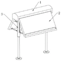
FIG. 1 is a schematic side view perspective view of the present invention;
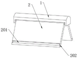
FIG. 2 is a schematic bottom perspective view of the present invention;
FIG. 3 is a schematic view of an assembled structure of the ridge bars and roof panels of the present invention;
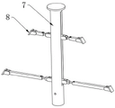
FIG. 4 is a schematic perspective view of the supporting mechanism of the present invention;
FIG. 5 is a perspective view of the support frame assembly of the present invention;
FIG. 6 is a cross-sectional structural view of the support frame assembly of the present invention;
FIG. 7 is an enlarged view of the structure at A in FIG. 6;
FIG. 8 is a schematic view of the assembled construction of the lift support bar assembly of the present invention;
FIG. 9 is a schematic cross-sectional view of the present invention;
FIG. 10 is an enlarged view of the structure at B in FIG. 9;
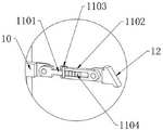
fig. 11 is an enlarged schematic view of the structure at C in fig. 9.
The reference numbers in the figures illustrate: 1. ridge strips; 2. a roof panel; 201. a rain guide groove; 202. a drain hole; 3. a support mechanism; 4. a support frame assembly; 5. an inclined support rod; 6. a horizontal connecting rod; 601. a left loop bar; 602. a right loop bar; 7. a central bone post; 701. a vertical through groove; 8. a lifting support rod assembly; 9. a lifting block; 10. an inner hinged seat; 11. the telescopic rod can be adjusted; 1101. a slide bar; 1102. a sliding sleeve; 1103. positioning the bolt; 1104. positioning holes; 1105. a through hole; 12. an outer hinged seat; 13. a vertical screw rod; 14. a drive gear set; 15. horizontally rotating the rod; 16. a gripping barrel; 17. a locking bolt; 18. and (7) supporting legs.
Detailed Description
The technical solution in the embodiments of the present invention will be clearly and completely described below with reference to the accompanying drawings in the embodiments of the present invention; it is to be understood that the embodiments described are merely exemplary embodiments, rather than exemplary embodiments, and that all other embodiments may be devised by those skilled in the art without departing from the scope of the present invention.
Referring to fig. 1 to 11, in an embodiment of the present invention, a movable-plate roof supporting structure includes a ridge bar 1, a set of mirror-image roof panels 2 hinged to the lower end of the ridge bar 1, and a supporting mechanism 3 disposed inside the roof panels 2; the supporting mechanism 3 comprises a plurality of groups of supporting frame components 4 which are distributed below the roof panel 2 at equal intervals; the support frame component 4 comprises a central bone column 7 fixedly connected with the central line position of the lower end surface of the ridge strip 1 and a plurality of groups of lifting support rod components 8 arranged on the central bone column 7; the lifting support rod assembly 8 comprises a lifting block 9 which is nested in the central bone pillar 7 and vertically slides with the central bone pillar 7, adjustable telescopic rods 11 which are hinged to two sides of the lifting block 9 and extend to the outer side of the central bone pillar 7, the outer ends of the adjustable telescopic rods are hinged to the inner wall of the roof panel, a vertical screw rod 13 which penetrates through the lifting block 9 and is in threaded connection with the lifting block 9, and a horizontal rotating rod 15 which is connected with the vertical screw rod 13 through a transmission gear set 14 for transmission and extends to the outer side of the central bone pillar 7; a horizontal rotating rod 15 is shared between adjacent support frame components 4, and an inclined support rod 5 is fixedly connected between adjacent central bone columns 7.
Specifically, when the movable plate house roof is installed, the horizontal rotating rods 15 are screwed, the horizontal rotating rods 15 drive the vertical screw rods 13 of the support frame assemblies 4 to rotate, the vertical screw rods 13 drive the lifting blocks 9 to move downwards, the lifting blocks 9 drive the adjustable telescopic rods 11 to rotate from a vertical state to a horizontal state, the adjustable telescopic rods 11 push the roof panels 2 to rotate from a vertical state to an inclined state, the roof is erected and installed quickly, after the installation is completed, a plurality of groups of lifting support rod assemblies 8 and the roof panels on two sides form a plurality of triangular stable support structures, meanwhile, a plurality of triangular support structures are formed by adjacent central bone columns 7 and inclined support rods 5 installed between the adjacent central bone columns 7, and the movable plate house roof has a good stable structure due to the support mechanisms 3;
meanwhile, the included angle between the roof panels 2 can be changed by adjusting the length of the adjustable telescopic rod 11, so that the inclination angle of the roof panels 2 is changed, the inclination of the roof is changed, and different installation requirements are met;
in addition, when carrying out the dismantlement of activity board room, reverse rotatory horizontal dwang 15 of twisting, horizontal dwang 15 drives each vertical lead screw 13 and rotates, and each elevator 9 of vertical lead screw 13 drive upwards moves, and elevator 9 drives roof boarding 2 through adjustable telescopic link 11 and does the removal in opposite directions for roof boarding 2 rotates vertical state from the tilt state and accomodates in the below of ridge strip 1, convenient hoist and mount and follow-up transportation, the transportation and the construction of the activity board room of being convenient for.
The upper end face of the ridge strip 1 is an arc face, the edge of the lower portion, close to the roof panel 2, of the lower portion is provided with a rain guide groove 201 arranged along the length direction of the roof panel 2, and the rear end of the roof panel 2 is provided with a drain hole 202 communicated with the rain guide groove 201.
Specifically, the roof strip 1 with the arc-shaped upper end face and the roof panel with the rain guide groove 201 and the drain hole 202 facilitate centralized drainage, and rainwater accumulation or rainwater dripping from the side face of the roof panel 2 is avoided.
In this embodiment, the roof panel 2 is a sandwich panel filled with thermal insulation material.
In particular, the heat insulation performance of the roof is ensured.
The front end and the rear end of the ridge strip 1 are provided with mounting plates, and the upper end of the roof panel 2 is fixedly connected with a hinged shaft which is rotatably connected with the mounting plates.
It is specific for roof boarding 2 articulates at the mounting panel inboard, makes roof boarding 2 be vertical state when accomodating and accomodates in ridge strip 1 inboardly, makes the roof shape after receiving difficulty more regular, the transportation and the handling of being convenient for.
The central bone column 7 is a hollow cylinder with an open lower end, a flange is arranged at the upper end of the central bone column 7, the flange is fixedly connected with the ridge strip 1 in a bolt fixing mode, and the central bone column 7 is provided with a vertical through groove 701 for allowing the adjustable telescopic rod 11 to slide up and down.
Particularly, the central bone column 7 is convenient to disassemble, and meanwhile, the cylindrical central bone column 7 has better torsion resistance.
The adjustable telescopic rod 11 comprises a sliding rod 1101, a sliding sleeve 1102 sleeved on the outer side of the sliding rod 1101, positioning bolts 1103 penetrating through the sliding sleeve 1102 and the sliding rod 1101, a plurality of groups of positioning holes 1104 arranged on the sliding rod 1101 at equal intervals, and through holes 1105 arranged at the inner end of the sliding sleeve 1102 and matched with the positioning holes 1104.
The sliding rod 1101 is hinged with the lifting block 9 through an inner hinge base 10, and the sliding sleeve 1102 is hinged with the inner wall of the roof panel 2 through an outer hinge base 12.
Specifically, conveniently adjust the length of adjustable telescopic link 11, and then adjust the angle of inclination on roof, adapt to different construction requirements.
Referring to fig. 9-11, in another embodiment of the present invention, a holding tube 16 is fixedly sleeved in the middle of the horizontal rotating rod 15, two sides of the holding tube 16 are rotatably connected with a horizontal connecting rod 6 sleeved outside the horizontal rotating rod 15, and the outer end of the horizontal connecting rod 6 is fixedly connected with the central bone pillar 7.
Annular grooves for accommodating the horizontal connecting rods 6 are formed in two sides of the holding cylinder 16, each horizontal connecting rod 6 comprises a left sleeve rod 601 fixedly connected with the left central bone pillar 7 and a right sleeve rod 602 fixedly connected with the right central bone pillar 7, and a locking bolt penetrating through the horizontal connecting rod 6 penetrates through the holding cylinder 16.
Specifically, a stable structure is formed among the adjacent central bone pillar 7, the diagonal support rod 5 and the horizontal connecting rod 6 by providing the horizontal connecting rod 6, and at the same time, the rotation of the horizontal rotating rod 15 by the holding cylinder 16 is not affected.
Referring to fig. 9 and 10, in another embodiment of the present invention, the lower ends of the central bone pillars 7 at both sides are threadedly connected with supporting legs 18, and the lower opening of the central bone pillar 7 is provided with internal threads.
In particular, the supporting legs 18 which are quickly disassembled and assembled provide support for the supporting mechanism 3, the roof quality is directly shared on the ground base, and the stability of the roof is improved.
The foregoing is only a preferred embodiment of the present invention; the scope of the invention is not limited thereto. Any person skilled in the art should also be able to cover the technical scope of the present invention by the equivalent or modified embodiments and the modified concepts of the present invention.
Claims (10)
1. A movable plate house roof supporting structure is characterized by comprising a ridge strip (1), a group of mirror image arranged roof plates (2) hinged with the lower end of the ridge strip (1), and a supporting mechanism (3) arranged on the inner side of the roof plates (2); the supporting mechanism (3) comprises a plurality of groups of supporting frame assemblies (4) which are distributed below the roof panel (2) at equal intervals;
the support frame assembly (4) comprises a central skeleton column (7) fixedly connected with the central line of the lower end surface of the ridge strip (1) and a plurality of groups of lifting support rod assemblies (8) arranged on the central skeleton column (7); the lifting support rod assembly (8) comprises a lifting block (9) which is nested in the central bone column (7) and vertically slides with the central bone column (7), adjustable telescopic rods (11) which extend to the outer side of the central bone column (7) and are hinged with the inner wall of the roof panel at the outer ends of the lifting block (9) and are hinged to the two sides of the lifting block (9), a vertical screw rod (13) which penetrates through the lifting block (9) and is in threaded connection with the lifting block (9), and a horizontal rotating rod (15) which is connected with the vertical screw rod (13) through a transmission gear set (14) for transmission and extends to the outer side of the central bone column (7); a horizontal rotating rod (15) is shared between the adjacent support frame components (4), and an inclined support rod (5) is fixedly connected between the adjacent central bone columns (7).
2. The movable plate house roof support structure according to claim 1, wherein a holding cylinder (16) is fixedly sleeved in the middle of the horizontal rotating rod (15), horizontal connecting rods (6) sleeved outside the horizontal rotating rod (15) are rotatably connected to two sides of the holding cylinder (16), and the outer ends of the horizontal connecting rods (6) are fixedly connected with the central bone pillar (7).
3. The movable floor house roof support structure according to claim 2, wherein the lower ends of the central skeleton pillars (7) located at both sides are screw-coupled with support legs (18), and the lower end opening of the central skeleton pillar (7) is provided with an internal thread.
4. The movable plate house roof support structure according to claim 1, wherein the upper end surface of the ridge strip (1) is an arc surface, the lower edge of the roof panel (2) near the lower edge is provided with a rain guide groove (201) arranged along the length direction of the roof panel (2), and the rear end of the roof panel (2) is provided with a drain hole (202) communicated with the rain guide groove (201).
5. A portable floor housing roof support structure according to claim 4, characterised in that the roof panels (2) are sandwich panels filled with insulation material.
6. The movable plate house roof support structure according to claim 4, wherein the front and rear ends of the ridge strip (1) are provided with mounting plates, and the upper end of the roof panel (2) is fixedly connected with a hinge shaft rotatably connected with the mounting plates.
7. The movable plate house roof support structure according to claim 1, wherein the central rib post (7) is a hollow cylinder with an open lower end, a flange is provided at the upper end of the central rib post (7) and is fixedly connected with the ridge strip (1) by means of bolt fastening, and the central rib post (7) is provided with a vertical through groove (701) for the adjustable telescopic rod (11) to slide up and down.
8. The movable floor house roof support structure according to claim 1, wherein the adjustable telescopic rod (11) comprises a sliding rod (1101), a sliding sleeve (1102) sleeved outside the sliding rod (1101), a positioning bolt (1103) penetrating through the sliding sleeve (1102) and the sliding rod (1101), a plurality of positioning holes (1104) arranged on the sliding rod (1101) and distributed at equal intervals, and a through hole (1105) arranged at the inner end of the sliding sleeve (1102) and matched with the positioning hole (1104).
9. The portable floor home roof support structure according to claim 8, wherein the sliding bar (1101) is hinged to the elevator block (9) by means of an inner hinge base (10), and the sliding sleeve (1102) is hinged to the inner wall of the roof panel (2) by means of an outer hinge base (12).
10. The movable floor house roof support structure according to claim 2, wherein the holding cylinder (16) is provided with annular grooves at both sides thereof for accommodating the horizontal connecting rods (6), the horizontal connecting rods (6) comprise a left loop bar (601) fixedly connected with the left central bone pillar (7) and a right loop bar (602) fixedly connected with the right central bone pillar (7), and the holding cylinder (16) is penetrated with a locking bolt penetrating through the horizontal connecting rods (6).
Priority Applications (1)
| Application Number | Priority Date | Filing Date | Title |
|---|---|---|---|
| CN202211137198.9A CN115233885B (en) | 2022-09-19 | 2022-09-19 | Movable board house roof supporting structure |
Applications Claiming Priority (1)
| Application Number | Priority Date | Filing Date | Title |
|---|---|---|---|
| CN202211137198.9A CN115233885B (en) | 2022-09-19 | 2022-09-19 | Movable board house roof supporting structure |
Publications (2)
| Publication Number | Publication Date |
|---|---|
| CN115233885A true CN115233885A (en) | 2022-10-25 |
| CN115233885B CN115233885B (en) | 2022-12-09 |
Family
ID=83681848
Family Applications (1)
| Application Number | Title | Priority Date | Filing Date |
|---|---|---|---|
| CN202211137198.9A Active CN115233885B (en) | 2022-09-19 | 2022-09-19 | Movable board house roof supporting structure |
Country Status (1)
| Country | Link |
|---|---|
| CN (1) | CN115233885B (en) |
Cited By (1)
| Publication number | Priority date | Publication date | Assignee | Title |
|---|---|---|---|---|
| CN115874749A (en) * | 2023-02-22 | 2023-03-31 | 江苏万融工程科技有限公司 | Movable board house roof |
-
2022
- 2022-09-19 CN CN202211137198.9A patent/CN115233885B/en active Active
Cited By (1)
| Publication number | Priority date | Publication date | Assignee | Title |
|---|---|---|---|---|
| CN115874749A (en) * | 2023-02-22 | 2023-03-31 | 江苏万融工程科技有限公司 | Movable board house roof |
Also Published As
| Publication number | Publication date |
|---|---|
| CN115233885B (en) | 2022-12-09 |
Similar Documents
| Publication | Publication Date | Title |
|---|---|---|
| EP2105573B1 (en) | A sliding door arrangement | |
| CN115233885B (en) | Movable board house roof supporting structure | |
| CN212130024U (en) | Support that building engineering used | |
| US20190118102A1 (en) | System for a tilting amusement ride | |
| CN219247764U (en) | Photovoltaic flexible support | |
| CN212388955U (en) | Hoisting construction scaffold for building construction | |
| CN212609380U (en) | Building electrical construction lifting device | |
| CN213329729U (en) | Steel construction of canopy | |
| CN113152675A (en) | Light steel assembled house structure | |
| CN215803035U (en) | Protective bracket for building construction | |
| CN217975564U (en) | Fabricated building supporting equipment for constructional engineering | |
| CN219864029U (en) | Roof steel support with high bearing capacity | |
| CN219364921U (en) | Connection structure of steel column and girder steel | |
| CN219341587U (en) | Lifting and feeding device for door and window frames | |
| CN218648758U (en) | Grouting-free dry prefabricated assembly type photovoltaic support base | |
| CN218375023U (en) | Climbing formula scaffold frame convenient to dismantle | |
| CN211949899U (en) | Fence for constructional engineering | |
| CN217079634U (en) | Support structure for lower support and vertical rod of scaffold | |
| CN215670084U (en) | Steel construction rotates connected node | |
| CN220301935U (en) | Combined building safety fence | |
| CN216893388U (en) | Temporary passing jump stand for house building construction | |
| CN214574658U (en) | Portable steel structure supporting beam | |
| CN218493058U (en) | Adjustable electric hanging basket system for slope roof | |
| CN211007825U (en) | Membrane structure bicycle shed convenient to installation | |
| CN219974044U (en) | Roof counter weight communication holding pole |
Legal Events
| Date | Code | Title | Description |
|---|---|---|---|
| PB01 | Publication | ||
| PB01 | Publication | ||
| SE01 | Entry into force of request for substantive examination | ||
| SE01 | Entry into force of request for substantive examination | ||
| GR01 | Patent grant | ||
| GR01 | Patent grant |