CN115215149A - Wire holder and wire holding method - Google Patents
Wire holder and wire holding method Download PDFInfo
- Publication number
- CN115215149A CN115215149A CN202210625336.1A CN202210625336A CN115215149A CN 115215149 A CN115215149 A CN 115215149A CN 202210625336 A CN202210625336 A CN 202210625336A CN 115215149 A CN115215149 A CN 115215149A
- Authority
- CN
- China
- Prior art keywords
- wire
- wheel
- rear side
- block
- holder
- Prior art date
- Legal status (The legal status is an assumption and is not a legal conclusion. Google has not performed a legal analysis and makes no representation as to the accuracy of the status listed.)
- Pending
Links
Images


Classifications
-
- B—PERFORMING OPERATIONS; TRANSPORTING
- B65—CONVEYING; PACKING; STORING; HANDLING THIN OR FILAMENTARY MATERIAL
- B65H—HANDLING THIN OR FILAMENTARY MATERIAL, e.g. SHEETS, WEBS, CABLES
- B65H51/00—Forwarding filamentary material
- B65H51/02—Rotary devices, e.g. with helical forwarding surfaces
- B65H51/04—Rollers, pulleys, capstans, or intermeshing rotary elements
- B65H51/06—Rollers, pulleys, capstans, or intermeshing rotary elements arranged to operate singly
-
- B—PERFORMING OPERATIONS; TRANSPORTING
- B65—CONVEYING; PACKING; STORING; HANDLING THIN OR FILAMENTARY MATERIAL
- B65H—HANDLING THIN OR FILAMENTARY MATERIAL, e.g. SHEETS, WEBS, CABLES
- B65H54/00—Winding, coiling, or depositing filamentary material
- B65H54/02—Winding and traversing material on to reels, bobbins, tubes, or like package cores or formers
- B65H54/40—Arrangements for rotating packages
- B65H54/44—Arrangements for rotating packages in which the package, core, or former is engaged with, or secured to, a driven member rotatable about the axis of the package
-
- B—PERFORMING OPERATIONS; TRANSPORTING
- B65—CONVEYING; PACKING; STORING; HANDLING THIN OR FILAMENTARY MATERIAL
- B65H—HANDLING THIN OR FILAMENTARY MATERIAL, e.g. SHEETS, WEBS, CABLES
- B65H54/00—Winding, coiling, or depositing filamentary material
- B65H54/02—Winding and traversing material on to reels, bobbins, tubes, or like package cores or formers
- B65H54/40—Arrangements for rotating packages
- B65H54/54—Arrangements for supporting cores or formers at winding stations; Securing cores or formers to driving members
- B65H54/547—Cantilever supporting arrangements
-
- B—PERFORMING OPERATIONS; TRANSPORTING
- B65—CONVEYING; PACKING; STORING; HANDLING THIN OR FILAMENTARY MATERIAL
- B65H—HANDLING THIN OR FILAMENTARY MATERIAL, e.g. SHEETS, WEBS, CABLES
- B65H54/00—Winding, coiling, or depositing filamentary material
- B65H54/70—Other constructional features of yarn-winding machines
-
- B—PERFORMING OPERATIONS; TRANSPORTING
- B65—CONVEYING; PACKING; STORING; HANDLING THIN OR FILAMENTARY MATERIAL
- B65H—HANDLING THIN OR FILAMENTARY MATERIAL, e.g. SHEETS, WEBS, CABLES
- B65H57/00—Guides for filamentary materials; Supports therefor
- B65H57/04—Guiding surfaces within slots or grooves
-
- B—PERFORMING OPERATIONS; TRANSPORTING
- B65—CONVEYING; PACKING; STORING; HANDLING THIN OR FILAMENTARY MATERIAL
- B65H—HANDLING THIN OR FILAMENTARY MATERIAL, e.g. SHEETS, WEBS, CABLES
- B65H2701/00—Handled material; Storage means
- B65H2701/30—Handled filamentary material
- B65H2701/34—Handled filamentary material electric cords or electric power cables
Landscapes
- Engineering & Computer Science (AREA)
- Textile Engineering (AREA)
- Processing Of Terminals (AREA)
Abstract
The invention discloses an electric wire retainer which comprises a retainer body, a wire fixing wheel, two positioning blocks, an extension plate and a fixing block, wherein the rear side of the extension plate is fixedly connected with the front side of the retainer body, the rear side of the wire fixing wheel is fixedly connected with the rear side of the inner wall of the retainer body, the rear sides of the two positioning blocks are fixedly connected with the rear side of the inner wall of the retainer body, the two positioning blocks are positioned at the top of the wire fixing wheel, a communication hole is formed in the bottom of the retainer body, the top of the fixing block is fixedly connected with the bottom of the retainer body, and a positioning mechanism is arranged inside the fixing block. According to the electric wire holder, the holder body, the wire fixing wheel, the two positioning blocks, the extension plate and the fixing blocks are matched for use, so that the internal wire can be held and tightened, the problem that the existing holding and tightening effects are poor is solved, and the electric wire holder has the advantage of good holding and tightening effects.
Description
Technical Field
The invention belongs to the technical field of wire holders, and particularly relates to a wire holder and a wire holding method.
Background
Wire holder, in order to satisfy the market demand, generally all until how better connection and how more convenient to use user use these aspects optimize, often neglected whether can the better maintenance of line, wire holder has, the effect of connection is better and more convenient to use these beneficial parts of user use, but has certain restriction, when normal use, if the line does not have fine maintenance and tighten up in inside, very easily causes the damage of line, the problem that prior art exists is: the holding and tightening effect is poor.
Disclosure of Invention
Aiming at the problems in the prior art, the invention provides an electric wire holder and an electric wire holding method, which have the advantages of good holding and tightening effects and solve the problem of poor holding and tightening effects in the prior art.
The invention is realized in such a way that an electric wire retainer comprises a retainer body, a wire fixing wheel, two positioning blocks, an extension plate and a fixing block, wherein the rear side of the extension plate is fixedly connected with the front side of the retainer body, the rear side of the wire fixing wheel is fixedly connected with the rear side of the inner wall of the retainer body, the rear sides of the two positioning blocks are fixedly connected with the rear side of the inner wall of the retainer body, the two positioning blocks are positioned at the top of the wire fixing wheel, the bottom of the retainer body is provided with a communication hole, the top of the fixing block is fixedly connected with the bottom of the retainer body, and a positioning mechanism is arranged inside the fixing block.
Preferably, the wire fixing wheel comprises a positioning column, the rear side of the positioning column is fixedly connected with the rear side of the inner wall of the retainer body, a hinge seat is fixedly installed at the front side of the positioning column, and the front side of the hinge seat is matched with the wire wheel.
Preferably, the wire wheel is fixedly provided with a plurality of arc-shaped blocks inside, and the arc-shaped blocks are uniformly distributed.
Preferably, the front side of the positioning block is provided with a plurality of strip-shaped grooves which are uniformly distributed.
Preferably, the positioning block is internally provided with a circular through hole, and annular hoops are fixedly arranged at openings at the top and the bottom of the circular through hole.
Preferably, the positioning mechanism comprises an arc-shaped extrusion block, the outer surface of the arc-shaped extrusion block is slidably connected with the inside of the fixed block, the bottom of the arc-shaped extrusion block is rotatably connected with a threaded rod, the bottom of the threaded rod penetrates through the fixed block and extends to the bottom of the fixed block, a rotating handle is fixedly mounted at the bottom of the threaded rod, a threaded through hole is formed in the fixed block, and the inside of the threaded through hole is in threaded connection with the outer surface of the threaded rod.
Preferably, the fixing block is internally provided with a limiting groove, the limiting groove is internally connected with a limiting block in a sliding manner, and one end of the limiting block, which is far away from the limiting groove, is fixedly connected with the outer surface of the arc-shaped extrusion block.
Preferably, a torsion block is fixedly mounted on the front side of the wire wheel, and the torsion block is located in the middle of the front side of the wire wheel.
Compared with the prior art, the invention has the following beneficial effects:
1. according to the invention, the wire retainer body, the wire fixing wheel, the two positioning blocks, the extension plate and the fixing block are matched for use, so that the internal wire can be retained and tightened, the problem of poor retaining and tightening effects in the prior art is solved, and the wire retainer has the advantage of good retaining and tightening effects.
2. The positioning device realizes the positioning of the wire wheel through the positioning column, and simultaneously utilizes the hinge seat, so that the rotation effect of the wire wheel is better, and the hinge seat is matched with the wire wheel in a tight fit manner, so that the wire wheel is fixed at a certain position when rotating to the certain position, and the tightening effect is better.
3. According to the invention, the arc-shaped blocks are arranged, so that the wire can be extruded, and the tightening effect is better.
4. The invention can realize preliminary limit by arranging the strip-shaped groove.
5. According to the invention, the wire can be better kept by arranging the circular through hole and the annular hoop.
6. According to the invention, the power source of the whole positioning mechanism is realized by manually rotating the rotating handle, and because the force can be transmitted, the rotating handle is rotated and simultaneously drives the threaded rod to move through the threaded through hole, so that the arc-shaped extrusion block can be pushed to move, and the wire can be kept better.
7. According to the invention, the arc-shaped extrusion block can move more stably by arranging the limiting groove and the limiting block.
8. According to the invention, the twisting block is arranged, so that the tightening effect of the wire wheel is better.
Drawings
FIG. 1 is a schematic diagram of a structure provided by an embodiment of the present invention;
FIG. 2 is a side view of a retainer body provided by an embodiment of the present invention;
FIG. 3 is a bottom view of a retainer body provided by an embodiment of the present invention;
FIG. 4 is a perspective view of a mounting block provided in accordance with an embodiment of the present invention;
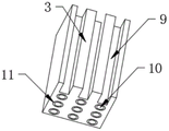
FIG. 5 is a perspective view of a locating block provided by an embodiment of the present invention;
FIG. 6 is a perspective view of a wire fixing wheel provided by an embodiment of the present invention;
fig. 7 is a detailed view of a positioning mechanism provided in an embodiment of the present invention.
In the figure: 1. a holder body; 2. a wire fixing wheel; 21. a positioning column; 22. a hinged seat; 23. a wire wheel; 3. positioning a block; 4. an extension plate; 5. a fixed block; 6. a communicating hole; 7. a positioning mechanism; 71. an arc-shaped extrusion block; 72. a threaded rod; 73. rotating the handle; 74. a threaded through hole; 8. an arc-shaped block; 9. a strip-shaped groove; 10. a circular through hole; 11. an annular ferrule; 12. a limiting groove; 13. a limiting block; 14. and (6) twisting the block.
Detailed Description
For further understanding of the contents, features and effects of the invention, the following examples are given in conjunction with the accompanying drawings.
The structure of the present invention will be described in detail below with reference to the accompanying drawings.
As shown in fig. 1 to 7, an electric wire holder provided in an embodiment of the present invention includes a holder body 1, a wire fixing wheel 2, two positioning blocks 3, an extension plate 4, and a fixing block 5, wherein a rear side of the extension plate 4 is fixedly connected to a front side of the holder body 1, a rear side of the wire fixing wheel 2 is fixedly connected to a rear side of an inner wall of the holder body 1, rear sides of the two positioning blocks 3 are fixedly connected to a rear side of an inner wall of the holder body 1, the two positioning blocks 3 are located at a top of the wire fixing wheel 2, a communication hole 6 is formed at a bottom of the holder body 1, a top of the fixing block 5 is fixedly connected to a bottom of the holder body 1, and a positioning mechanism 7 is disposed inside the fixing block 5.
Referring to fig. 6, the wire fixing wheel 2 includes a positioning column 21, a rear side of the positioning column 21 is fixedly connected with a rear side of an inner wall of the holder body 1, a hinge seat 22 is fixedly installed at a front side of the positioning column 21, and a wire wheel 23 is used in cooperation with the front side of the hinge seat 22.
Adopt above-mentioned scheme: realize the location to the line wheel 23 through reference column 21, utilize articulated seat 22 simultaneously, just so can make the rotatory effect of line wheel 23 better, be the tight fit because of articulated seat 22 with the cooperation of line wheel 23 to realize that line wheel 23 rotates to what position just fixes in what position, make the effect of tightening up better.
Referring to fig. 6, the inside of the reel 23 is fixedly provided with a plurality of arc blocks 8, and the arc blocks 8 are uniformly distributed.
Adopt above-mentioned scheme: through setting up arc piece 8, just so can realize the extrusion to the line, the effect of tightening up simultaneously is better.
Referring to fig. 5, a plurality of strip-shaped grooves 9 are formed in the front side of the positioning block 3, and the strip-shaped grooves 9 are uniformly distributed.
Adopt above-mentioned scheme: through setting up bar groove 9, just so can realize preliminary spacing.
Referring to fig. 5, a circular through hole 10 is formed in the positioning block 3, and annular collars 11 are fixedly mounted at openings at the top and the bottom of the circular through hole 10.
Adopt above-mentioned scheme: by providing the circular through hole 10 and the annular ferrule 11, a better holding effect of the wire can be achieved.
Referring to fig. 7, the positioning mechanism 7 includes an arc-shaped extrusion block 71, an outer surface of the arc-shaped extrusion block 71 is slidably connected with an inner portion of the fixed block 5, a threaded rod 72 is rotatably connected to a bottom of the arc-shaped extrusion block 71, a bottom of the threaded rod 72 penetrates through the fixed block 5 and extends to the bottom of the fixed block 5, a rotating handle 73 is fixedly mounted at the bottom of the threaded rod 72, a threaded through hole 74 is formed in the fixed block 5, and an inner portion of the threaded through hole 74 is in threaded connection with an outer surface of the threaded rod 72.
The scheme is adopted: the power source of the whole positioning mechanism 7 is realized by rotating the rotating handle 73 by manpower, and because the force can be transmitted, the threaded rod 72 is driven to move by the threaded through hole 74 while the rotating handle 73 is rotated, so that the arc-shaped extrusion block 71 can be pushed to move, and the holding effect of the wire can be better.
Referring to fig. 7, a limiting groove 12 is formed in the fixing block 5, a limiting block 13 is slidably connected to the inside of the limiting groove 12, and one end of the limiting block 13, which is far away from the limiting groove 12, is fixedly connected to the outer surface of the arc-shaped extrusion block 71.
The scheme is adopted: by arranging the limiting groove 12 and the limiting block 13, the arc-shaped extrusion block 71 can move more stably.
Referring to fig. 1, 2 and 3, a torsion block 14 is fixedly mounted on the front side of the pulley 23, and the torsion block 14 is located in the middle of the front side of the pulley 23.
The scheme is adopted: by providing the torsion block 14, the tightening effect of the pulley 23 can be improved.
A wire holding method comprising the steps of:
the first step is as follows: threading the electric wire into the interior of the holder;
the second step is that: fixing the wire through a fixing block;
the third step: the internal wire is fastened through a manual rotating wire wheel;
the fourth step: the wire is fixed by the retainer body, so that the connection is convenient.
The working principle of the invention is as follows:
when using, at first realize the power supply of whole positioning mechanism 7 through the rotatory twist grip 73 of manpower, because of power can be transmitted, drive threaded rod 72 through screw through-hole 74 and remove when rotatory twist grip 73, just so can realize promoting arc extrusion piece 71 and remove, set up spacing groove 12 and stopper 13 simultaneously, just so can make the removal of arc extrusion piece 71 more stable, simultaneously through setting up circular through-hole 10 and annular cuff 11, just so can make the keeping effect of line better, secondly realize the location to line wheel 23 through reference column 21, utilize articulated seat 22 simultaneously, just so can make the rotatory effect of line wheel 23 better, because of articulated seat 22 is the tight fit with the cooperation of line wheel 23, thereby realize that what position just fixed is in what position is rotated to line wheel 23, make the effect of tightening up better.
In summary, the following steps: this electric wire keeps ware uses through the cooperation that sets up and keep ware body 1, solidus wheel 2, two locating pieces 3, extension board 4 and fixed block 5, just so can realize keeping and tightening up inside line, has solved the current poor problem of effect of keeping and tightening up.
It is noted that, herein, relational terms such as first and second, and the like may be used solely to distinguish one entity or action from another entity or action without necessarily requiring or implying any actual such relationship or order between such entities or actions. Also, the terms "comprises," "comprising," or any other variation thereof, are intended to cover a non-exclusive inclusion, such that a process, method, article, or apparatus that comprises a list of elements does not include only those elements but may include other elements not expressly listed or inherent to such process, method, article, or apparatus.
Although embodiments of the present invention have been shown and described, it will be appreciated by those skilled in the art that various changes, modifications, substitutions and alterations can be made in these embodiments without departing from the principles and spirit of the invention, the scope of which is defined in the appended claims and their equivalents.
Claims (9)
1. The utility model provides an electric wire keeps ware, keeps ware body (1), solidus wheel (2), two locating pieces (3), extension board (4) and fixed block (5), its characterized in that including keeping: the rear side of extension board (4) and the front side fixed connection who keeps ware body (1), the rear side of solidus wheel (2) and the rear side fixed connection who keeps ware body (1) inner wall, the rear side of two locating pieces (3) and the rear side fixed connection who keeps ware body (1) inner wall, two locating pieces (3) are located the top of solidus wheel (2), intercommunicating pore (6) have been seted up to the bottom of keeping ware body (1), the top of fixed block (5) and the bottom fixed connection who keeps ware body (1), the inside of fixed block (5) is provided with positioning mechanism (7).
2. A wire holder as defined in claim 1, wherein: the wire fixing wheel (2) comprises a positioning column (21), the rear side of the positioning column (21) is fixedly connected with the rear side of the inner wall of the retainer body (1), an articulated seat (22) is fixedly mounted on the front side of the positioning column (21), and the wire fixing wheel (23) is matched with the front side of the articulated seat (22) to use.
3. A wire holder as defined in claim 2, wherein: the inside fixed mounting of line wheel (23) has arc piece (8), the quantity of arc piece (8) is a plurality of, and evenly distributed.
4. A wire holder as defined in claim 1, wherein: the front side of locating piece (3) is opened and is equipped with bar groove (9), the quantity of bar groove (9) is a plurality of, and evenly distributed.
5. A wire holder as defined in claim 1, wherein: circular through-hole (10) have been seted up to the inside of locating piece (3), annular cuff (11) are all fixed mounting to the opening part at circular through-hole (10) top and bottom.
6. A wire holder as defined in claim 1, wherein: positioning mechanism (7) include arc extrusion piece (71), the surface of arc extrusion piece (71) and the inside sliding connection of fixed block (5), the bottom of arc extrusion piece (71) is rotated and is connected with threaded rod (72), the bottom of threaded rod (72) is run through fixed block (5) and is extended to the bottom of fixed block (5), the bottom fixed mounting of threaded rod (72) has twist grip (73), threaded through-hole (74) has been seted up to the inside of fixed block (5), the inside of threaded through-hole (74) and the surface threaded connection of threaded rod (72).
7. A wire holder as defined in claim 6, wherein: spacing groove (12) have been seted up to the inside of fixed block (5), the inside sliding connection of spacing groove (12) has stopper (13), the one end that spacing groove (12) were kept away from in stopper (13) is connected with the external fixed surface of arc extrusion piece (71).
8. A wire holder as defined in claim 2, wherein: the front side of the wire wheel (23) is fixedly provided with a twisting block (14), and the twisting block (14) is positioned in the middle of the front side of the wire wheel (23).
9. An electric wire holding method characterized by: the method comprises the following steps:
the first step is as follows: threading the electric wire into the interior of the holder;
the second step is that: fixing the wire through a fixing block;
the third step: the internal wire is fastened through a manual rotating wire wheel;
the fourth step: the wire is fixed by the retainer body, so that the connection is convenient.
Priority Applications (1)
| Application Number | Priority Date | Filing Date | Title |
|---|---|---|---|
| CN202210625336.1A CN115215149A (en) | 2022-06-02 | 2022-06-02 | Wire holder and wire holding method |
Applications Claiming Priority (1)
| Application Number | Priority Date | Filing Date | Title |
|---|---|---|---|
| CN202210625336.1A CN115215149A (en) | 2022-06-02 | 2022-06-02 | Wire holder and wire holding method |
Publications (1)
| Publication Number | Publication Date |
|---|---|
| CN115215149A true CN115215149A (en) | 2022-10-21 |
Family
ID=83607230
Family Applications (1)
| Application Number | Title | Priority Date | Filing Date |
|---|---|---|---|
| CN202210625336.1A Pending CN115215149A (en) | 2022-06-02 | 2022-06-02 | Wire holder and wire holding method |
Country Status (1)
| Country | Link |
|---|---|
| CN (1) | CN115215149A (en) |
Citations (14)
| Publication number | Priority date | Publication date | Assignee | Title |
|---|---|---|---|---|
| KR19990068766A (en) * | 1999-06-18 | 1999-09-06 | 배상준 | Holder for winding the wire |
| JP2002199553A (en) * | 2000-12-28 | 2002-07-12 | Furukawa Electric Co Ltd:The | Cable wiring apparatus |
| US7381080B1 (en) * | 2007-09-05 | 2008-06-03 | Wen-Cheng Lai | Electrical cord retention device |
| CN102714362A (en) * | 2009-12-01 | 2012-10-03 | 矢崎总业株式会社 | Wire holder |
| KR101815461B1 (en) * | 2017-09-01 | 2018-01-05 | (주)전우종합기술 | Holding device for underground distribution line |
| CN208849112U (en) * | 2018-11-07 | 2019-05-10 | 苏州卓德电子有限公司 | It is a kind of with the crimp type terminal for being stably connected with structure |
| CN210260685U (en) * | 2019-02-25 | 2020-04-07 | 苏州华仁科技有限公司 | Rubber tube winding machine |
| CN211110437U (en) * | 2019-12-19 | 2020-07-28 | 江苏杰特隆电缆科技有限公司 | Soot blower expansion cable pay-off |
| CN211265842U (en) * | 2020-01-17 | 2020-08-14 | 惠州市太基精密电子有限公司 | Electric connector |
| CN214281575U (en) * | 2021-04-07 | 2021-09-24 | 南京源兴智达信息科技有限公司 | Terminal clustering ultra-high mobility broadband communication device |
| CN215478857U (en) * | 2021-09-01 | 2022-01-11 | 河南秋海新能源汽车零部件有限公司 | Anti-winding wire arranging disc for mounting automobile wire harness |
| CN215580196U (en) * | 2021-08-18 | 2022-01-18 | 辛楠 | Branch box for network engineering convenient to it is categorised |
| CN216189937U (en) * | 2021-08-09 | 2022-04-05 | 西宁方盛电力设计有限公司 | Guyed disk for electric power construction |
| CN114280745A (en) * | 2021-12-30 | 2022-04-05 | 安徽森联信息科技有限公司 | Corridor light sub-box for three-network integrated optical fiber access |
-
2022
- 2022-06-02 CN CN202210625336.1A patent/CN115215149A/en active Pending
Patent Citations (14)
| Publication number | Priority date | Publication date | Assignee | Title |
|---|---|---|---|---|
| KR19990068766A (en) * | 1999-06-18 | 1999-09-06 | 배상준 | Holder for winding the wire |
| JP2002199553A (en) * | 2000-12-28 | 2002-07-12 | Furukawa Electric Co Ltd:The | Cable wiring apparatus |
| US7381080B1 (en) * | 2007-09-05 | 2008-06-03 | Wen-Cheng Lai | Electrical cord retention device |
| CN102714362A (en) * | 2009-12-01 | 2012-10-03 | 矢崎总业株式会社 | Wire holder |
| KR101815461B1 (en) * | 2017-09-01 | 2018-01-05 | (주)전우종합기술 | Holding device for underground distribution line |
| CN208849112U (en) * | 2018-11-07 | 2019-05-10 | 苏州卓德电子有限公司 | It is a kind of with the crimp type terminal for being stably connected with structure |
| CN210260685U (en) * | 2019-02-25 | 2020-04-07 | 苏州华仁科技有限公司 | Rubber tube winding machine |
| CN211110437U (en) * | 2019-12-19 | 2020-07-28 | 江苏杰特隆电缆科技有限公司 | Soot blower expansion cable pay-off |
| CN211265842U (en) * | 2020-01-17 | 2020-08-14 | 惠州市太基精密电子有限公司 | Electric connector |
| CN214281575U (en) * | 2021-04-07 | 2021-09-24 | 南京源兴智达信息科技有限公司 | Terminal clustering ultra-high mobility broadband communication device |
| CN216189937U (en) * | 2021-08-09 | 2022-04-05 | 西宁方盛电力设计有限公司 | Guyed disk for electric power construction |
| CN215580196U (en) * | 2021-08-18 | 2022-01-18 | 辛楠 | Branch box for network engineering convenient to it is categorised |
| CN215478857U (en) * | 2021-09-01 | 2022-01-11 | 河南秋海新能源汽车零部件有限公司 | Anti-winding wire arranging disc for mounting automobile wire harness |
| CN114280745A (en) * | 2021-12-30 | 2022-04-05 | 安徽森联信息科技有限公司 | Corridor light sub-box for three-network integrated optical fiber access |
Non-Patent Citations (1)
| Title |
|---|
| 关长毅: "电器辅件与连接技术", 低压电器, no. 03, pages 37 - 40 * |
Similar Documents
| Publication | Publication Date | Title |
|---|---|---|
| CN212080307U (en) | Portable valve opener capable of being adjusted in telescopic mode | |
| CN115215149A (en) | Wire holder and wire holding method | |
| CN217102460U (en) | Convenient radiating optical cable production is with packing rope transmission device | |
| CN209009863U (en) | A kind of data line storage device | |
| CN214188964U (en) | Rotary clamping mechanism for cylindrical barrel digital printing | |
| CN210997965U (en) | Grinding device is used in fishhook production | |
| CN211164127U (en) | Plate cutting machine for acrylic plate | |
| CN220314513U (en) | Automatic plate feeding structure of packaging printer | |
| CN211984279U (en) | Plastic oil drum cleaning device | |
| CN218776955U (en) | Blanking pipe cooling water jacket assembly | |
| CN211185533U (en) | Portable assembled fishing rod | |
| CN112641411A (en) | Clean steel wire ball centre gripping equipment of using in family kitchen | |
| CN217412611U (en) | Cutting device is used in automobile-used accessory production | |
| CN113225419A (en) | Mobile phone desktop support capable of being used with mobile phone | |
| CN214890239U (en) | Business administration is with device of explaining | |
| CN213622756U (en) | Winding device is assisted to raw sticky tape | |
| CN210099976U (en) | Toolbox for interior decoration | |
| CN216143138U (en) | Coupling assembling for transmission case | |
| CN214323018U (en) | Fixing clamp for machining notebook computer connecting shaft | |
| CN211465760U (en) | PVC pipe processingequipment for interior decoration | |
| CN218819165U (en) | Intelligent information terminal support | |
| CN216656870U (en) | Welding rod clamping device for welding | |
| CN219707622U (en) | Finished product scroll strorage device | |
| CN213771276U (en) | Multifunctional bottle opener | |
| CN218743699U (en) | Pipeline inner wall dirt cleaning mechanism |
Legal Events
| Date | Code | Title | Description |
|---|---|---|---|
| PB01 | Publication | ||
| PB01 | Publication | ||
| SE01 | Entry into force of request for substantive examination | ||
| SE01 | Entry into force of request for substantive examination |