CN115172104A - Bridge type double-breakpoint contactor and breaker - Google Patents
Bridge type double-breakpoint contactor and breaker Download PDFInfo
- Publication number
- CN115172104A CN115172104A CN202211031117.7A CN202211031117A CN115172104A CN 115172104 A CN115172104 A CN 115172104A CN 202211031117 A CN202211031117 A CN 202211031117A CN 115172104 A CN115172104 A CN 115172104A
- Authority
- CN
- China
- Prior art keywords
- contact
- static
- normally closed
- normally open
- iron core
- Prior art date
- Legal status (The legal status is an assumption and is not a legal conclusion. Google has not performed a legal analysis and makes no representation as to the accuracy of the status listed.)
- Granted
Links
- 230000003068 static effect Effects 0.000 claims abstract description 141
- 230000007246 mechanism Effects 0.000 claims abstract description 16
- 238000000926 separation method Methods 0.000 claims abstract description 7
- 230000001360 synchronised effect Effects 0.000 claims abstract description 5
- XEEYBQQBJWHFJM-UHFFFAOYSA-N Iron Chemical group [Fe] XEEYBQQBJWHFJM-UHFFFAOYSA-N 0.000 claims description 118
- 229910052742 iron Inorganic materials 0.000 claims description 29
- 238000009434 installation Methods 0.000 claims description 21
- 238000004146 energy storage Methods 0.000 claims description 16
- 239000003990 capacitor Substances 0.000 claims description 15
- BQCADISMDOOEFD-UHFFFAOYSA-N Silver Chemical compound [Ag] BQCADISMDOOEFD-UHFFFAOYSA-N 0.000 claims description 9
- 229910052709 silver Inorganic materials 0.000 claims description 9
- 239000004332 silver Substances 0.000 claims description 9
- XUIMIQQOPSSXEZ-UHFFFAOYSA-N Silicon Chemical compound [Si] XUIMIQQOPSSXEZ-UHFFFAOYSA-N 0.000 claims description 2
- 229910052710 silicon Inorganic materials 0.000 claims description 2
- 239000010703 silicon Substances 0.000 claims description 2
- 238000010586 diagram Methods 0.000 description 10
- 230000009471 action Effects 0.000 description 7
- 230000008859 change Effects 0.000 description 3
- 230000000694 effects Effects 0.000 description 3
- 238000000034 method Methods 0.000 description 3
- 230000001052 transient effect Effects 0.000 description 3
- 238000005265 energy consumption Methods 0.000 description 2
- 230000002441 reversible effect Effects 0.000 description 2
- RYGMFSIKBFXOCR-UHFFFAOYSA-N Copper Chemical compound [Cu] RYGMFSIKBFXOCR-UHFFFAOYSA-N 0.000 description 1
- 230000009286 beneficial effect Effects 0.000 description 1
- 229910052802 copper Inorganic materials 0.000 description 1
- 239000010949 copper Substances 0.000 description 1
- 230000005672 electromagnetic field Effects 0.000 description 1
- 230000003993 interaction Effects 0.000 description 1
- 239000000463 material Substances 0.000 description 1
- 230000004048 modification Effects 0.000 description 1
- 238000012986 modification Methods 0.000 description 1
- 230000008569 process Effects 0.000 description 1
- 238000006467 substitution reaction Methods 0.000 description 1
Images


Classifications
-
- H—ELECTRICITY
- H01—ELECTRIC ELEMENTS
- H01H—ELECTRIC SWITCHES; RELAYS; SELECTORS; EMERGENCY PROTECTIVE DEVICES
- H01H50/00—Details of electromagnetic relays
- H01H50/16—Magnetic circuit arrangements
-
- H—ELECTRICITY
- H01—ELECTRIC ELEMENTS
- H01H—ELECTRIC SWITCHES; RELAYS; SELECTORS; EMERGENCY PROTECTIVE DEVICES
- H01H50/00—Details of electromagnetic relays
- H01H50/16—Magnetic circuit arrangements
- H01H50/36—Stationary parts of magnetic circuit, e.g. yoke
-
- H—ELECTRICITY
- H01—ELECTRIC ELEMENTS
- H01H—ELECTRIC SWITCHES; RELAYS; SELECTORS; EMERGENCY PROTECTIVE DEVICES
- H01H50/00—Details of electromagnetic relays
- H01H50/44—Magnetic coils or windings
-
- H—ELECTRICITY
- H01—ELECTRIC ELEMENTS
- H01H—ELECTRIC SWITCHES; RELAYS; SELECTORS; EMERGENCY PROTECTIVE DEVICES
- H01H50/00—Details of electromagnetic relays
- H01H50/54—Contact arrangements
-
- H—ELECTRICITY
- H01—ELECTRIC ELEMENTS
- H01H—ELECTRIC SWITCHES; RELAYS; SELECTORS; EMERGENCY PROTECTIVE DEVICES
- H01H71/00—Details of the protective switches or relays covered by groups H01H73/00 - H01H83/00
- H01H71/10—Operating or release mechanisms
- H01H71/12—Automatic release mechanisms with or without manual release
- H01H71/14—Electrothermal mechanisms
- H01H71/16—Electrothermal mechanisms with bimetal element
Abstract
The invention discloses a bridge type double-breakpoint contactor and a bridge type double-breakpoint breaker.A permanent magnet matching mechanism is arranged in the middle of a fixed rack shell and is provided with two groups of electromagnets and permanent magnets, wherein one electromagnet and one permanent magnet form one group, and under the normal condition, one group is in a pull-in state, and the other group is in a separation state; the permanent magnet permanent-magnet synchronous motor is also provided with a moving contact gap bridge contact piece and a moving contact and static contact main switch consisting of two groups of static contact brackets, and a normally open and normally closed auxiliary contact switch consisting of a normally open and normally closed auxiliary gap bridge contact piece, a normally open static contact and a normally closed static contact, wherein attraction force or repulsion force is generated between the electromagnet and the permanent magnet to drive the moving contact and static contact main switch and the normally open and normally closed auxiliary contact switch to be switched on or switched off. The invention is provided with the structure that the electromagnet and the permanent magnet are mutually matched, the on-off control of the contactor circuit can be realized by applying short-term direct current pulse to the electromagnetic coil of the electromagnet, the structure is simple, the use is convenient, the electromagnetic coil does not need to be continuously powered, and the electric energy is saved.
Description
Technical Field
The invention relates to the technical field of contactors and circuit breakers, in particular to a bridge type double-breakpoint circuit breaker contactor and a circuit breaker.
Background
The traditional contactor enables the moving and static iron cores of the electromagnet to be attracted by electrifying the electromagnetic coil, so that the moving contact mechanism attached to the moving iron core of the electromagnet is contacted with the static contact, and the circuit is conducted. In order to keep the circuit on, the electromagnetic coil needs to be kept in a power supply state for a long time, and in the world where energy saving is promoted, a new mode is urgently needed to be invented to replace the mode of the conventional contactor on-off power circuit, namely a broken contactor mode.
Disclosure of Invention
The invention aims to provide a bridge type double-breakpoint contactor and a breaker.A moving contact mechanism adopts a mechanical structure that a magnetic line closed permanent magnet is matched with a moving magnet, and the opening and closing of the breaking contactor can be realized by applying transient direct current pulse to an electromagnetic coil of an electromagnet and controlling the current direction of the direct current pulse; for the traditional circuit breaker, a complex mechanical energy storage opening and closing mechanism is also saved.
In order to achieve the purpose, the invention provides the following scheme:
a bridge type double-breakpoint contactor comprises a fixed rack shell, wherein an installation channel is arranged in the middle of the fixed rack shell, an electric permanent magnet matching mechanism is arranged in the installation channel and comprises a first static magnet, a movable frame and a second static magnet which are sequentially arranged from top to bottom, the first static magnet is fixedly arranged at the top end of the installation channel, the second static magnet is fixedly arranged at the bottom end of the installation channel, the movable frame is slidably connected with the installation channel, and a space distance for the movable frame to slide is preset in the installation channel; the movable frame is of an upper-middle-lower three-layer structure, a first moving magnet and a second moving magnet are symmetrically arranged on the upper layer and the lower layer, a plurality of moving contact gap bridge contact pieces and contact pressure springs are arranged on the middle layer, the moving contact gap bridge contact pieces are arranged below the moving magnets, and the contact pressure springs are arranged between the moving contact gap bridge contact pieces and the second moving magnets;
two groups of static contacts matched with the moving contact gap bridge contact piece are installed on the fixed rack shell, the two groups of static contacts are respectively positioned at the left (incoming line end) and right (outgoing line end) two ends of the moving contact gap bridge contact piece, silver contacts corresponding up and down are respectively arranged at the end part of the static contact and the two ends of the moving contact gap bridge contact piece, and the moving contact gap bridge contact piece and the two groups of static contacts form a moving contact main switch;
the upper layer of the movable frame is also provided with a normally open and normally closed auxiliary gap bridge contact piece, two groups of normally open static contacts and normally closed static contacts are installed on the shell of the fixed frame and are respectively positioned at the left side and the right side of the normally open and normally closed auxiliary gap bridge contact piece, each group of the normally open static contacts and normally closed static contacts are respectively arranged at the upper side and the lower side of the normally open and normally closed auxiliary gap bridge contact piece in a matching way, the normally open and normally closed auxiliary gap bridge contact piece, the normally open static contacts and the normally closed static contacts jointly form a normally open and normally closed auxiliary contact switch, the normally open and normally closed auxiliary contact switch and the normally open static contacts form a normally open auxiliary contact switch, and the normally open auxiliary contact switch and the movable and static contact main switch are in the same on-off logic; the normally open and normally closed auxiliary gap bridge contact piece and the normally closed static contact form a normally closed auxiliary contact switch, and the on-off logic of the normally closed auxiliary contact switch is opposite to that of the movable and static contact main switch;
the normally open static contact and the normally closed static contact are respectively connected with an external control wiring terminal, and the two groups of static contact brackets are respectively connected with an inlet wire terminal and an outlet wire terminal; the external control wiring terminal, the incoming line terminal and the outgoing line terminal are arranged on the fixed frame shell;
the static magnet I and the static magnet II are both electromagnets, and the moving magnet I and the moving magnet II are both permanent magnets; the electromagnet comprises an iron framework and an electromagnetic coil, the iron framework comprises a columnar structure and iron discs arranged at two ends of the columnar structure, and the electromagnetic coil is wound on the columnar structure; the permanent magnet is arranged in an iron magnetic tank with an opening, the permanent magnet is only in attraction contact with the bottom of the iron magnetic tank and keeps a certain gap with the periphery of the iron magnetic tank, the height of the permanent magnet arranged in the iron magnetic tank is slightly lower than the opening of the iron magnetic tank to form a height difference, and the height difference forms a magnetic gap generated when the permanent magnet is attracted with an iron disc of the electromagnet;
and direct current pulses are respectively applied to the electromagnetic coils of the two electromagnets, one electromagnet and the opposite permanent magnet form a pair of combinations, one pair of combinations is in an attraction state, and the other pair of combinations is in a separation state, so that the movable frame drives the movable and fixed contact main switch and the normally open and normally closed auxiliary contact switch to be switched on or switched off.
Furthermore, still be provided with two sets of arc control devices in the fixed frame casing, install respectively in two sets of static contacts below, arc control device includes a plurality of arc chutes and leads the arc board, two lead arc board bottom electric connection.
Further, the contactor still is provided with the automatic separating brake device that has a power failure, the automatic separating brake device that has a power failure includes energy storage capacitor and control scheme PCB board, control scheme PCB board with energy storage capacitor connects, energy storage capacitor and two the solenoid of electro-magnet passes through silicon controlled rectifier electric connection.
Further, the contactor further comprises a base, and the fixed frame shell is arranged on the base.
Furthermore, a manual closing button and a manual opening button are further arranged on the fixed rack shell.
A bridge type double-breakpoint circuit breaker is improved based on the bridge type double-breakpoint contactor, wherein the sliding connection between a movable frame and an installation channel is changed into that: guide sleeves are arranged on two sides of the movable frame, guide pillars are arranged on the fixed frame shell, and the guide sleeves are sleeved on the guide pillars in a sliding manner;
the moving contact gap bridge contact plate, the contact pressure spring, the moving iron core I and the moving iron core II which are arranged in the movable frame are kept unchanged; the structure moves up and down along the guide sleeve and the guide pillar along with the movable frame; a static contact corresponding to the outlet end of the moving contact gap bridge contact piece is replaced by a static contact connecting piece, and a current sensor is sleeved on the static contact connecting piece; one end of the bimetallic strip is welded at the necking part of the static contact connecting sheet, the other end of the bimetallic strip is connected with a thermal adjusting screw in a threaded manner, and the inner side of the bimetallic strip is provided with a thermal current limiting contact sheet corresponding to the thermal adjusting screw; the thermal adjusting screw is electrically connected with the thermal current limiting contact piece when the bimetallic strip is heated and bent; the electronic control circuit board controls the opening and closing of the circuit breaker.
According to the specific embodiment provided by the invention, the bridge type double-breakpoint circuit breaker contactor and the circuit breaker provided by the invention have the following technical effects:
(1) Two pairs of electromagnets and permanent magnets are arranged, one electromagnet and one permanent magnet form a pair of combinations, under normal conditions, one pair of combinations is in an attraction state, the other pair of combinations is in a separation state, on-off control of a related power circuit can be realized only by applying a very short direct current pulse to an electromagnetic coil, the electromagnetic coil does not need to be kept in an electrified state, and energy can be saved; particularly, after the electromagnetic coil is powered off, the movable iron core and the static iron core form a magnetic line of force closed type magnetic closed loop to form a switch opening and closing bistable structure;
(2) The permanent magnet is provided with an iron magnetic tank, the height of the permanent magnet in the magnetic tank is slightly lower than the opening of the magnetic tank, so that a height difference is formed, the height difference forms a magnetic gap generated when the permanent magnet is attracted with an iron disc at the end part of the electromagnet, and the interaction effect between the electromagnet and the permanent magnet is improved;
(3) The movable frame is of an upper-middle-lower three-layer structure, can freely move in one dimension within a reserved space distance, and drives the main switch of the moving and static contacts and the normally open and normally closed auxiliary contact switch to be switched on or off under the action of magnetic force;
(4) The method comprises the steps that an automatic power failure brake separating device is arranged, the automatic power failure brake separating device is composed of an energy storage capacitor and a control circuit PCB, the energy storage capacitor is fully charged under the condition that an upper port is electrified, once an inlet port of a contactor is powered off, the energy storage capacitor rapidly releases full electric energy to two electromagnetic coils, one electromagnet is instantly charged with magnetic polarity repulsive to a relative permanent magnet, the other electromagnet is also instantly charged with magnetic polarity attracted to the relative permanent magnet, and as long as the inlet port of the contactor is powered off, a moving contact bridging contact piece and a normally-open and normally-closed auxiliary bridging contact piece can be pulled down and are separated from contact with a corresponding static contact;
(5) The current-limiting thermal assembly and the current sensor are added, and the contactor can be changed into a circuit breaker by increasing the number of arc-extinguishing grids.
Drawings
In order to more clearly illustrate the embodiments of the present invention or the technical solutions in the prior art, the drawings needed to be used in the embodiments will be briefly described below, and it is obvious that the drawings in the following description are only some embodiments of the present invention, and it is obvious for those skilled in the art to obtain other drawings without inventive exercise.
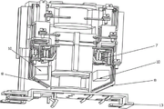
Fig. 1a is a schematic view of an internal structure of a bridge-type double-breakpoint contactor in a disconnection state of a moving contact and a fixed contact main switch contact according to an embodiment of the invention;
fig. 1b is a schematic structural diagram of an electric permanent magnet matching mechanism in the off state of a main switch contact of a moving contact and a static contact in the embodiment of the invention;
FIG. 2a is a schematic structural diagram of a bridge-type dual-breakpoint contactor according to an embodiment of the present invention when a main circuit and an auxiliary circuit are in a conducting state;
FIG. 2b is a schematic structural diagram of the electro-permanent magnet matching mechanism when the main and auxiliary circuits are in a conducting state according to the embodiment of the present invention;
FIG. 3a is a schematic structural view of an upper permanent magnet according to an embodiment of the present invention;
FIG. 3b is a schematic structural diagram of a lower permanent magnet according to an embodiment of the present invention;
FIG. 4a is a schematic structural diagram of an upper electromagnet according to an embodiment of the present invention;
FIG. 4b is a schematic structural diagram of a lower electromagnet according to an embodiment of the present invention;
FIG. 5a is a schematic view of a package structure of a movable frame according to an embodiment of the present invention;
FIG. 5b is a schematic cross-sectional view of a movable frame according to an embodiment of the present invention;
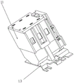
FIGS. 6 a-6 b are schematic diagrams illustrating the overall structure of a bridge-type dual-break contactor according to an embodiment of the present invention in two directions;
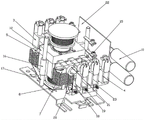
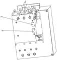
fig. 7 is a schematic diagram of an internal structure of a bridge-type double-break-point circuit breaker according to an embodiment of the present invention;
fig. 8 a-8 b are schematic diagrams illustrating the overall structure of a bridge-type double-break-point circuit breaker according to an embodiment of the present invention in two directions;
reference numerals: 1a, a first static iron core; 1am, upper electromagnetic coil; 1b, a static iron core II; 1bm, lower electromagnetic coil; 2a, a movable iron core I; 2an, an upper iron magnetic tank; 2b, a movable iron core II; 2bn, a lower iron magnetic tank; 3. an incoming terminal; 4. an outlet terminal; 5. static contacts (including inlet terminal static contacts and outlet terminal static contacts); 6. a moving contact gap bridge contact piece; 7. an arc chute; 8. an arc guide plate; 9. a contact pressure spring; 10. the automatic brake-separating device is powered off; 11. fixing the frame shell; 12. a movable frame; 13. a base; 14. a normally open and normally closed auxiliary contact switch; 14a, a normally open and normally closed auxiliary gap bridge contact piece; 14b, a normally open static contact; 14c, a normally closed static contact; 15. an external control wiring terminal; 16. a guide sleeve; 17. a guide post; 18. a bimetal; 19. a thermal set screw; 20. a thermal current limiting contact; 21. a current sensor; 22. an electronic control circuit board; 23. a static contact connecting sheet; 24. a manual closing button; 25. and a manual brake-separating button.
Detailed Description
The technical solutions in the embodiments of the present invention will be clearly and completely described below with reference to the drawings in the embodiments of the present invention, and it is obvious that the described embodiments are only a part of the embodiments of the present invention, and not all of the embodiments. All other embodiments, which can be derived by a person skilled in the art from the embodiments given herein without making any creative effort, shall fall within the protection scope of the present invention.
The invention aims to provide a bridge type double-breakpoint circuit breaker, a contactor, a circuit breaker, a permanent magnet and a control circuit, wherein the structure that an electromagnet is matched with the permanent magnet is arranged, the on-off control of the circuit of the contactor can be realized by applying short-term direct current pulse to an electromagnetic coil of the electromagnet, the structure is simple, the use is convenient, the electromagnetic coil does not need to be continuously powered, and the magnetic line of force of the permanent magnet is in a closed stable state.
In order to make the aforementioned objects, features and advantages of the present invention comprehensible, embodiments accompanied with figures are described in further detail below.
As shown in fig. 1a to 6b, the bridge type double-breakpoint contactor provided by the invention comprises a base 13 and a fixed frame shell 11 arranged on the base 13, wherein an installation channel is arranged in the middle of the fixed frame shell 11, an electric permanent magnet matching mechanism is arranged in the installation channel, the electric permanent magnet matching mechanism comprises a first static iron core 1a, a movable frame 12 and a second static iron core 1b which are sequentially arranged from top to bottom, the first static iron core 1a is fixedly arranged at the top end of the installation channel, the second static iron core 1b is fixedly arranged at the bottom end of the installation channel, the movable frame 12 is slidably connected with the installation channel, and a spatial distance for the movable frame 12 to slide is preset in the installation channel; the movable frame 12 is of an upper-middle-lower three-layer structure, a movable iron core I2 a and a movable iron core II 2b are symmetrically arranged on the upper layer and the lower layer, a plurality of movable contact gap bridge contact pieces 6 and contact pressure springs 9 are arranged on the middle layer, the movable contact gap bridge contact pieces 6 are arranged below the movable iron core I2 a, and the contact pressure springs 9 are arranged between the movable contact gap bridge contact pieces 6 and the movable iron core II 2b;
two groups of static contacts 5 matched with the moving contact gap bridge contact piece 6 are installed on the fixed rack shell 11, the two groups of static contacts 5 are respectively positioned at the left (inlet wire end) and right (outlet wire end) two ends of the moving contact gap bridge contact piece 6 and are respectively an inlet wire end static contact and an outlet wire end static contact, the end part of the static contact 5 and the two ends of the moving contact gap bridge contact piece 6 are respectively provided with silver contacts corresponding to each other up and down, and the moving contact gap bridge contact piece 6 and the two groups of static contacts 5 form a moving contact main switch;
a normally open and normally closed auxiliary gap contact 14a is further arranged on the upper layer of the movable frame 12, two groups of normally open static contacts 14b and normally closed static contacts 14c are mounted on the fixed frame shell 11 and are respectively located on the left side and the right side of the normally open and normally closed auxiliary gap contact 14a, each group of the normally open static contacts 14b and normally closed static contacts 14c are respectively arranged on the upper side and the lower side of the normally open and normally closed auxiliary gap contact 14a in a matching manner, and the normally open and normally closed auxiliary gap contact 14a, the normally open static contacts 14b and the normally closed static contacts 14c jointly form a normally open and normally closed auxiliary contact switch 14; the normally open and normally closed auxiliary gap bridge contact piece 14a and the normally open static contact 14b form a normally open auxiliary contact switch, and the on-off logic of the normally open auxiliary contact switch is the same as that of the static and dynamic contact main switch; the normally open and normally closed auxiliary gap bridge contact piece 14a and the normally closed static contact 14c form a normally closed auxiliary contact switch, and the on-off logic of the normally closed auxiliary contact switch is opposite to that of the dynamic and static contact main switch;
the normally open static contact 14b and the normally closed static contact 14c are respectively connected with an external control wiring terminal 15, and the two groups of static contacts 5 are respectively connected with an inlet wire terminal 3 and an outlet wire terminal 4; the external control wiring terminal 15, the incoming line terminal 3 and the outgoing line terminal 4 are arranged on the fixed frame shell 11;
in the specific embodiment of the invention, the adopted scheme is as follows: the first static iron core 1a and the second static iron core 1b are electromagnets and respectively correspond to the upper electromagnet and the lower electromagnet; the first movable iron core 2a and the second movable iron core 2b are permanent magnets and respectively correspond to the upper permanent magnet and the lower permanent magnet; as shown in fig. 4a and 4b, the electromagnet comprises an iron skeleton and electromagnetic coils (as shown by an upper electromagnetic coil 1am and a lower electromagnetic coil 1 bm), the iron skeleton comprises a columnar structure and iron discs arranged at two ends of the columnar structure, and the electromagnetic coils are wound on the columnar structure;
as shown in fig. 3a and 3b, the permanent magnet is disposed in an iron magnetic tank with an opening, the permanent magnet is only in attraction contact with the bottom of the iron magnetic tank and keeps a certain gap with the periphery of the iron magnetic tank, the height of the permanent magnet disposed in the iron magnetic tank is slightly lower than the opening of the iron magnetic tank (as shown by 2an and 2 bn), so as to form a height difference, and the height difference constitutes a magnetic gap generated when the permanent magnet is attracted with an iron disc of the electromagnet;
two pairs of electromagnets and permanent magnets are arranged, one electromagnet and one permanent magnet form a pair of combinations, and under normal conditions, one pair of combinations is in an attraction state, and the other pair of combinations is in a separation state; the permanent magnet in each pair of electromagnet and permanent magnet combination and the permanent magnet in the other pair of combination are arranged in the same movable frame 12, and the two permanent magnets arranged in the movable frame 12 are a movable iron core I2 a and a movable iron core II 2b; the static iron core I1 a is used as an upper electromagnet, an upper electromagnetic coil 1am is wound on the periphery of the static iron core I, a static iron core II 1b is used as a lower electromagnet and a lower electromagnetic coil 1bm is wound on the periphery of the static iron core I, the upper electromagnet and the lower electromagnet are opposite to each other at the position to form two static iron cores for pulling space distance, and the static contact 5 (a plurality of incoming wires and outgoing wires) is assembled with the incoming wire terminals 3 (a plurality of incoming wires) and the outgoing wire terminals 4 (a plurality of incoming wires and outgoing wires) and is also fixedly installed on the rack shell 11; the movable frame 12 with the two permanent magnets can move freely in one dimension within the space distance. The moving space distance is the contact opening and closing distance of the contactor.
Two groups of arc extinguishing devices are further arranged in the fixed rack shell 11 and are respectively installed below the two groups of static contacts 5, each arc extinguishing device comprises a plurality of arc extinguishing grids 7 and arc guide plates 8, and the bottoms of the arc guide plates 8 at the wire inlet end and the wire outlet end are electrically connected.
The contactor is further provided with an automatic power failure opening device 10, and the automatic power failure opening device 10 comprises an energy storage capacitor and a control circuit PCB. The automatic power failure opening device 10 comprises an energy storage capacitor and a control circuit PCB, the control circuit PCB is connected with the energy storage capacitor, and the energy storage capacitor is connected with two electromagnetic coils of the electromagnets. The control circuit PCB board is used to change the current direction of the upper and lower electromagnetic coils 1am and 1bm, so that the corresponding electromagnets change polarity, and the control principle is well known in the art and will not be described herein. And the fixed rack shell 11 is also provided with a manual closing button 24 and a manual opening button 25 which are connected with the control circuit PCB.
The embodiment of the invention discloses a contactor for connecting/disconnecting a three-phase live wire, wherein three moving contact gap bridge contact pieces 6 and six static contacts 5 arranged on the contactor are in a separated state, the six static contacts 5 are respectively connected to three incoming wire terminals 3 and three outgoing wire terminals 4, two silver contacts are welded at two ends of each moving contact gap bridge contact piece 6, and the silver contacts are also welded at positions on each static contact 5 corresponding to the silver contacts of the moving contact gap bridge contact piece 6.
As can be seen from the structural diagrams provided in fig. 5a and 5b, the movable contact gap bridge contact 6 of ABC three-phase power is installed at the middle layer of the movable frame 12, and a contact pressure spring 9 is arranged below each movable contact gap bridge contact and has the function of ensuring that a certain contact pressure is maintained in the whole over-travel range when 12 silver contacts of the movable/static contacts are in contact; as can be seen from fig. 2a and 2b, in the three-phase electrical conduction operating state of the contactor, the moving contact bridge contact piece 6 is already in contact with the fixed contact 5, and the moving contact bridge contact piece 6 presses down the contact pressure spring 9 by a distance, which is the above-mentioned over-travel range; the normally open and normally closed auxiliary contact switch 14 has a function of performing synchronous on-off switching on a control circuit depending on the up-down switching action of the movable frame 12, and it is further noted from the second drawing that one silver contact at each end of the normally open and normally closed auxiliary bridge contact 14a corresponds to two fixed contact silver contacts up and down respectively, the upper part corresponds to a normally open fixed contact 14b (which is logically consistent with the on-off state of the fixed contact 5 and keeps synchronous on-off), and the lower part corresponds to a normally closed fixed contact 14c (which is logically opposite to the on-off state of the fixed contact 5); the external control connecting terminal 15 is electrically and tightly connected with an external lead to control the up-and-down motion of the moving contact mechanism, thereby achieving the purpose of controlling the on-off of the main and auxiliary circuits.
The function of a conventional contactor is: the electromagnetic coil is powered on and powered off, so that the electromagnetic movable iron core and the static iron core generate attraction and release actions, the main contact and the auxiliary contact attached to the movable iron core generate synchronous following actions and are in contact with and disconnected from the main static contact and the auxiliary static contact, and therefore the functions of cutting off and switching on a main circuit and an auxiliary circuit are achieved. When the machine equipment needs to be started, the control circuit sends out an instruction, or an operator presses a start button, the electromagnetic coil is electrified, the movable iron core is attracted with the main contact and the auxiliary contact attached to the movable iron core and is contacted with the main contact and the auxiliary contact, the main circuit and the auxiliary circuit are switched on, and even if the operator lifts the operation button, the control circuit continuously supplies power to the electromagnetic coil through the switched-on auxiliary contact, so that the conduction state of the main circuit is ensured; when the main circuit needs to be cut off, only the power supply of the electromagnetic coil is cut off; most importantly, when the commercial power is cut off, the electromagnetic coil of the traditional contactor loses power, the electromagnet releases the main contact and the auxiliary contact, and the machine equipment is stopped. When the power supply is recovered to normal, the operation process of the starting device must be repeated.
The invention can realize the substitution of the traditional contactor through the arrangement of the structure, when the circuit needs to be switched on, only one or short direct current pulse needs to be applied to the lower electromagnetic coil 1bm, the electromagnetic field generated by the pulse enables the second static iron core 1b serving as the lower electromagnet to be magnetized, the polarity of the charged electromagnetic is the same as that of the second positively attracted moving iron core (lower permanent magnet) 2b, the original attraction force is instantly changed into a repulsive force, and the second moving iron core (lower permanent magnet) 2b which is originally in the attraction state is forced to be rapidly separated from the second static iron core 1 b; at the same time, the upper electromagnetic coil 1am of the other set of cores, which is in a distant separated state, similarly receives a dc pulse, and the magnetic field generated in the upper stationary core 1a is different in magnetic polarity from the movable core (upper permanent magnet) 2a, thereby generating an attractive force. The two permanent magnets are arranged together with the movable frame 12, the movable contact gap bridge contact piece 6 is arranged on the middle layer of the movable frame 12, and the normally open and normally closed auxiliary gap bridge contact piece 14a arranged on the outer side of the movable frame 12 are fixed together to form a movable contact mechanism, the movable contact mechanism moves to the other end attached with a static contact under the push-pull action of the two forces, the pair of combined electromagnet (a static iron core 1 a) and the permanent magnet (a movable iron core 2 a) which are originally in a separated state are attracted together, the static contact 5 and the normally open static contact 14b are also connected and conducted under the action of the movable contact gap bridge contact piece 6 and the normally open and normally closed auxiliary gap bridge contact piece 14a, at the moment, the upper electromagnetic coil 1am can keep a circuit smooth without being electrified, and the purpose of saving energy is achieved. When the main and sub circuits are to be disconnected, only the dc pulses in the opposite directions may be applied to the upper and lower electromagnetic coils 1am and 1 bm.
In addition, the electromagnetic coil of the traditional contactor cannot generate suction force under the condition of power failure, so that the fixed contact and the normally-open auxiliary fixed contact of the traditional contactor are always kept in an off state. The electromagnet (the first static iron core 1 a) and the permanent magnet (the first movable iron core 2 a) are attracted together after power failure, and the attraction is permanent magnet attraction which is irrelevant to the power supply of the inlet port of the contactor, so that all the movable and static contacts cannot be separated, particularly the auxiliary normally open contact is changed into a normally closed reverse logic state, and any dangerous condition can occur once the power supply is restored. According to the invention, an energy storage capacitor is arranged on one side of the inlet end port of the contactor, and is fully charged under the condition that the upper port is charged, once the inlet end port of the contactor is powered off, the fully charged electric energy is rapidly released to two electromagnetic coils 1am and 1bm by the energy storage capacitor, an electromagnet 1a is instantly charged with the magnetic polarity which is repulsive to a permanent magnet 2a, and an electromagnet 1b is also charged with the magnetic polarity which is attracted to the permanent magnet 2b, so that the result is that: as long as the inlet port of the contactor is powered off, all the moving contact gap bridge contact pieces 6 including the normally open and normally closed auxiliary gap bridge contact piece 14a are pulled down to be separated from contact with the corresponding static contact.
In another embodiment, the first static magnet and the second static magnet are both permanent magnets, the first moving magnet and the second moving magnet are both electromagnets, and connecting wires of the electromagnetic washers are changed into flexible wire connection; the principle is the same as the above embodiments, the current direction of the electromagnetic coil of the electromagnet is changed, so that attraction force or repulsion force is generated between the static magnet I and the moving magnet I, and repulsion force or attraction force is generated between the static magnet II and the moving magnet II, namely, one electromagnet and one permanent magnet form a group, under normal conditions, one group is in an attraction state, and the other group is in a separation state, so that the cooperation effect is formed.
The invention has the advantages that: 1. under the normal working condition of the electrical equipment, the electromagnetic coil does not need to be kept in a power-on state, so that the energy consumption can be saved; 2. the electromagnetic coils 1am and 1bm can use fewer turns, and can greatly save copper material consumption. The product of the amperage and the number of turns which determine the electromagnetic force can be compensated in a current increasing manner, and the problem of too high temperature rise cannot be caused because the huge current is instantaneous. The manual closing button 24 and the manual opening button 25 are provided for the convenience of manually operating the opening and closing, and are also implemented by applying a forward and reverse direct current pulse to the electromagnetic coil.
As shown in fig. 7, 8a and 8b, the present invention further provides a bridge type double-break-point circuit breaker structure, which is obtained by replacing and adding several components on the basis of the contactor structure, wherein the added components include a current sensor 21, a bimetallic strip 18, a static contact connecting piece 23, a thermal current limiting contact piece 20 and a thermal adjusting screw 19, and the added components are used for increasing short-circuit protection and current overload protection functions, which are also basic functions of the circuit breaker. In order to improve the breaking capacity, the number of the arc-extinguishing grids 7 is increased. The electronic control circuit board 22 is enlarged for convenient operation of the circuit breaker.
In particular, the sliding connection of the mobile frame 12 to the installation channel is changed to: guide sleeves 16 are arranged on two sides of the movable frame 12, a guide post 17 is arranged on the fixed frame shell 11, and the guide sleeves 16 are sleeved on the guide post 17 in a sliding manner;
the original structure moving contact gap bridge contact 6, the contact pressure spring 9, the first moving iron core 2a and the second moving iron core 2b which are arranged in the movable frame 12 are kept unchanged; the structure moves up and down along the guide sleeve 16 and the guide post 17 along with the movable frame 12; a static contact 5 corresponding to the outlet end of the moving contact gap bridge contact sheet 6 is replaced by a static contact connecting sheet 23, and the current sensor 21 is sleeved on the static contact connecting sheet 23; one end of the bimetallic strip 18 is welded at the necking part of the static contact connecting sheet 23, the other end of the bimetallic strip is connected with a thermal adjusting screw 19 in a threaded manner, and the inner side of the bimetallic strip 18 is provided with a thermal current limiting contact sheet 20 corresponding to the thermal adjusting screw 19; the thermal adjusting screw 19 is electrically connected with the thermal current limiting contact piece 20 when the bimetallic strip 18 is heated and bent; the electronic control circuit board 22 controls the opening and closing of the circuit breaker, and the electronic control circuit board 22 corresponds to a control circuit PCB board in the contactor. The circuit breaker is provided with a manual closing button 24 and a manual opening button 25 which are respectively connected with the electronic control circuit board 22.
The structural modification of the guide post 17 and the guide bush 16 in fig. 7 is not related to the addition of the circuit breaker function, and can also be applied to the contactor, only for the structural change of the movable frame 12 and the fixed frame shell 11, but the frictional resistance of the guide post and guide bush structure can be greatly reduced.
The contactor and the circuit breaker are different in that the circuit breaker is additionally provided with a bimetallic current limiting device and a current sensor on the basis of the contactor. The electromagnetic permanent magnet closed-type double-combination electric permanent magnet switching-on and switching-off mechanism has the common point that the magnetic line closed-type double-combination electric permanent magnet switching-on and switching-off mechanism is arranged in the middle of the fixed rack shell, the switching-on and switching-off mechanism is provided with two groups of electromagnets and permanent magnets, one electromagnet and one permanent magnet form one group, and under the normal condition, one group is in an attraction state, and the other group is in a separation state; the magnets arranged at the top and the bottom are static magnets, the moving magnets are arranged between the static magnets, and a group of moving contact gap bridge contact pieces and two groups of static contacts are also arranged to form a moving and static contact main switch; meanwhile, a normally open and normally closed auxiliary contact switch is arranged; the attraction force or repulsion force generated between the electromagnet and the permanent magnet drives the dynamic and static contact main switch and the normally open and normally closed auxiliary contact switch to be switched on or off. The invention is provided with a structure that the electromagnet and the permanent magnet are mutually matched, the opening and closing control of the moving and static contacts of the contactor or the circuit breaker can be realized by applying transient direct current pulse to the electromagnetic coil of the electromagnet, the structure is simple, the use is convenient, the electromagnetic coil is not like a common contactor to continuously supply power, only extremely transient pulse electric energy is consumed when the opening and closing action is carried out, and the energy consumption is greatly saved. The invention has the greatest beneficial effects that the invention is very convenient for network automation control; the contactor and the circuit breaker have the common point that when the external power supply stops supplying power, the contactor and the circuit breaker are automatically in an opening state.
The principles and embodiments of the present invention have been explained herein using specific embodiments, which are merely used to help understand the method and its core ideas of the present invention; meanwhile, for a person skilled in the art, according to the idea of the present invention, the specific embodiments and the application range may be changed. In view of the above, the present disclosure should not be construed as limiting the invention.
Claims (6)
1. A bridge type double-breakpoint contactor, comprising: the permanent magnet synchronous motor comprises a fixed rack shell (11), wherein an installation channel is arranged in the middle of the fixed rack shell (11), an electric permanent magnet matching mechanism is arranged in the installation channel and comprises a first static iron core (1 a), a movable frame (12) and a second static iron core (1 b) which are sequentially arranged from top to bottom, the first static iron core (1 a) is fixedly arranged at the top end of the installation channel, the second static iron core (1 b) is fixedly arranged at the bottom end of the installation channel, the movable frame (12) is connected with the installation channel in a sliding mode, and a spatial distance for the movable frame (12) to slide is preset in the installation channel; the movable frame (12) is of an upper-middle-lower three-layer structure, a first movable iron core (2 a) and a second movable iron core (2 b) are symmetrically arranged on the upper layer and the lower layer, a plurality of movable contact gap bridge contact pieces (6) and contact pressure springs (9) are arranged on the middle layer, the movable contact gap bridge contact pieces (6) are arranged below the first movable iron core (2 a), and the contact pressure springs (9) are arranged between the movable contact gap bridge contact pieces (6) and the second movable iron core (2 b);
two groups of static contacts (5) matched with the moving contact gap bridge contact piece (6) are installed on the fixed rack shell (11), the two groups of static contacts (5) are respectively positioned at an incoming line end and an outgoing line end of the moving contact gap bridge contact piece (6), silver contacts corresponding to each other up and down are respectively arranged at the end part of the static contact (5) and the two ends of the moving contact gap bridge contact piece (6), and the moving contact gap bridge contact piece (6) and the two groups of static contacts (5) form a moving contact and static contact main switch;
a normally open and normally closed auxiliary gap bridge contact piece (14 a) is further arranged on the upper layer of the movable frame (12), two groups of normally open static contacts (14 b) and normally closed static contacts (14 c) are mounted on the fixed rack shell (11) and are respectively located on the left side and the right side of the normally open and normally closed auxiliary gap bridge contact piece (14 a), each group of normally open static contacts (14 b) and normally closed static contacts (14 c) are respectively arranged on the upper side and the lower side of the normally open and normally closed auxiliary gap bridge contact piece (14 a) in a matched mode, and the normally open and normally closed auxiliary gap bridge contact piece (14 a), the normally open static contacts (14 b) and the normally closed static contacts (14 c) jointly form a normally open and normally closed auxiliary contact switch (14); the normally open and normally closed auxiliary gap bridge contact piece (14 a) and the normally open static contact (14 b) form a normally open auxiliary contact switch, and the on-off logic of the normally open auxiliary contact switch is the same as that of the dynamic and static contact main switch; the normally open and normally closed auxiliary gap bridge contact piece (14 a) and the normally closed static contact (14 c) form a normally closed auxiliary contact switch, and the on-off logic of the normally closed auxiliary contact switch is opposite to that of the dynamic and static contact main switch;
the normally open static contact (14 b) and the normally closed static contact (14 c) are respectively connected with an external control wiring terminal (15), and the two groups of static contacts (5) are respectively connected with an incoming line terminal (3) and an outgoing line terminal (4); the external control wiring terminal (15), the incoming line terminal (3) and the outgoing line terminal (4) are arranged on the fixed rack shell (11);
the first static iron core (1 a) and the second static iron core (1 b) are electromagnets, and the first movable iron core (2 a) and the second movable iron core (2 b) are permanent magnets; or the static magnet I (1 a) and the static magnet II (1 b) are both permanent magnets, and the moving magnet I (2 a) and the moving magnet II (2 b) are both electromagnets;
the electromagnet comprises an iron framework and an electromagnetic coil, the iron framework comprises a columnar structure and iron discs arranged at two ends of the columnar structure, and the electromagnetic coil is wound on the columnar structure; the permanent magnet is arranged in an iron magnetic tank with an opening, the permanent magnet is only in attraction contact with the bottom of the iron magnetic tank and keeps a certain gap with the periphery of the iron magnetic tank, the height of the permanent magnet arranged in the iron magnetic tank is slightly lower than the opening of the iron magnetic tank to form a height difference, and the height difference forms a magnetic gap generated when the permanent magnet is attracted with an iron disc of the electromagnet;
direct current pulses are respectively applied to the electromagnetic coils of the two electromagnets, one electromagnet and the opposite permanent magnet form a pair of combinations, one pair of combinations is in an attraction state, the other pair of combinations is in a separation state, and the movable frame (12) and the movable contact gap bridge contact piece (6) move up and down by changing the current direction of the direct current pulses to drive the movable contact main switch and the normally open and normally closed auxiliary contact switch (14) to be switched on or switched off.
2. A bridge type double break contactor as claimed in claim 1, wherein said fixed frame housing (11) further comprises two sets of arc extinguishing devices installed below two sets of static contacts (5), said arc extinguishing devices comprising a plurality of arc chutes (7) and arc guide plates (8), and bottoms of said arc guide plates (8) on left and right sides are electrically connected.
3. A bridge type double-breakpoint contactor according to claim 1, wherein the contactor is further provided with a power failure automatic opening device (10), the power failure automatic opening device (10) comprises an energy storage capacitor and a control circuit PCB, the control circuit PCB controls the energy storage capacitor to be charged and discharged, and the energy storage capacitor is electrically connected with electromagnetic coils of the two electromagnets through a silicon controlled rectifier.
4. A bridge double break contactor according to claim 1, characterized in that said contactor further comprises a base (13), said stationary gantry housing (11) being arranged on said base (13).
5. A bridge double break contactor according to claim 1, characterized in that said fixed frame housing (11) is further provided with a manual closing button (24) and a manual opening button (25).
6. A bridge type double break point circuit breaker improved on the basis of a bridge type double break point contactor as claimed in any one of claims 1 to 5, characterized in that the sliding connection of said movable frame (12) to said installation channel is changed to: guide sleeves (16) are arranged on two sides of the movable frame (12), a guide post (17) is arranged on the fixed rack shell (11), and the guide sleeves (16) are sleeved on the guide post (17) in a sliding manner;
the moving contact gap bridge contact piece (6), the contact pressure spring (9), the moving iron core I (2 a) and the moving iron core II (2 b) which are arranged in the moving frame (12) and have the original structure are kept unchanged; the structure moves up and down along the guide sleeve (16) and the guide post (17) along with the movable frame (12); a static contact (5) corresponding to the outlet end of the moving contact gap bridge contact sheet (6) is replaced by a static contact connecting sheet (23), and a current sensor (21) is sleeved on the static contact connecting sheet (23); one end of the bimetallic strip (18) is welded at the necking part of the static contact connecting sheet (23), the other end of the bimetallic strip is connected with a thermal adjusting screw (19) in a threaded manner, and the inner side of the bimetallic strip (18) is provided with a thermal current limiting contact sheet (20) corresponding to the thermal adjusting screw (19); the thermal adjusting screw (19) is electrically connected with the thermal current limiting contact piece (20) when the bimetallic strip (18) is heated and bent; an electronic control circuit board (22) controls the opening and closing of the circuit breaker.
Priority Applications (1)
| Application Number | Priority Date | Filing Date | Title |
|---|---|---|---|
| CN202211031117.7A CN115172104B (en) | 2022-08-26 | 2022-08-26 | Bridge type double-breakpoint contactor and breaker |
Applications Claiming Priority (1)
| Application Number | Priority Date | Filing Date | Title |
|---|---|---|---|
| CN202211031117.7A CN115172104B (en) | 2022-08-26 | 2022-08-26 | Bridge type double-breakpoint contactor and breaker |
Publications (2)
| Publication Number | Publication Date |
|---|---|
| CN115172104A true CN115172104A (en) | 2022-10-11 |
| CN115172104B CN115172104B (en) | 2024-03-29 |
Family
ID=83481420
Family Applications (1)
| Application Number | Title | Priority Date | Filing Date |
|---|---|---|---|
| CN202211031117.7A Active CN115172104B (en) | 2022-08-26 | 2022-08-26 | Bridge type double-breakpoint contactor and breaker |
Country Status (1)
| Country | Link |
|---|---|
| CN (1) | CN115172104B (en) |
Cited By (2)
| Publication number | Priority date | Publication date | Assignee | Title |
|---|---|---|---|---|
| CN116054379A (en) * | 2023-03-29 | 2023-05-02 | 江苏智泰新能源科技有限公司 | Switch device for safe power supply of household energy storage sodium ion battery |
| CN116844919A (en) * | 2023-09-01 | 2023-10-03 | 新乡市景弘电气有限公司 | Electromagnetic relay capable of being rapidly broken |
Citations (6)
| Publication number | Priority date | Publication date | Assignee | Title |
|---|---|---|---|---|
| CN2261082Y (en) * | 1996-02-09 | 1997-08-27 | 天津市第二继电器厂 | Solenoid type dc. contactor |
| KR100899432B1 (en) * | 2008-09-02 | 2009-05-27 | 주식회사 케이디파워 | An economy in power consumption type electromagnetic contactor |
| WO2013097698A1 (en) * | 2011-12-26 | 2013-07-04 | 上海电科电器科技有限公司 | Contact structure of low-voltage electrical apparatus |
| CN204809068U (en) * | 2015-06-12 | 2015-11-25 | 西安开天铁路电气股份有限公司 | Double break point DC electromagnetic contactor |
| CN110137044A (en) * | 2019-05-30 | 2019-08-16 | 天津加美特电气设备有限公司 | A kind of intelligent circuit breaker with normally-open normally-close function |
| CN113421806A (en) * | 2021-07-28 | 2021-09-21 | 天津加美特电气股份有限公司 | DPN electric leakage circuit breaker with combined type electromagnetism tripping device |
-
2022
- 2022-08-26 CN CN202211031117.7A patent/CN115172104B/en active Active
Patent Citations (6)
| Publication number | Priority date | Publication date | Assignee | Title |
|---|---|---|---|---|
| CN2261082Y (en) * | 1996-02-09 | 1997-08-27 | 天津市第二继电器厂 | Solenoid type dc. contactor |
| KR100899432B1 (en) * | 2008-09-02 | 2009-05-27 | 주식회사 케이디파워 | An economy in power consumption type electromagnetic contactor |
| WO2013097698A1 (en) * | 2011-12-26 | 2013-07-04 | 上海电科电器科技有限公司 | Contact structure of low-voltage electrical apparatus |
| CN204809068U (en) * | 2015-06-12 | 2015-11-25 | 西安开天铁路电气股份有限公司 | Double break point DC electromagnetic contactor |
| CN110137044A (en) * | 2019-05-30 | 2019-08-16 | 天津加美特电气设备有限公司 | A kind of intelligent circuit breaker with normally-open normally-close function |
| CN113421806A (en) * | 2021-07-28 | 2021-09-21 | 天津加美特电气股份有限公司 | DPN electric leakage circuit breaker with combined type electromagnetism tripping device |
Non-Patent Citations (2)
| Title |
|---|
| 孙华浩;: "发射机控制电路中交流接触器的维护使用", 西部广播电视, no. 09, 5 May 2017 (2017-05-05), pages 215 * |
| 鲍光海;: "具有短路分断功能的智能交流接触器", 电器与能效管理技术, no. 09, 15 May 2018 (2018-05-15), pages 31 - 37 * |
Cited By (3)
| Publication number | Priority date | Publication date | Assignee | Title |
|---|---|---|---|---|
| CN116054379A (en) * | 2023-03-29 | 2023-05-02 | 江苏智泰新能源科技有限公司 | Switch device for safe power supply of household energy storage sodium ion battery |
| CN116844919A (en) * | 2023-09-01 | 2023-10-03 | 新乡市景弘电气有限公司 | Electromagnetic relay capable of being rapidly broken |
| CN116844919B (en) * | 2023-09-01 | 2024-01-16 | 新乡市景弘电气有限公司 | Electromagnetic relay capable of being rapidly broken |
Also Published As
| Publication number | Publication date |
|---|---|
| CN115172104B (en) | 2024-03-29 |
Similar Documents
| Publication | Publication Date | Title |
|---|---|---|
| CN115172104B (en) | Bridge type double-breakpoint contactor and breaker | |
| CN107946133B (en) | Quick separating brake mechanism and hybrid alternating current circuit breaker | |
| CN214254245U (en) | Intelligent permanent magnet vacuum contactor | |
| CN108550503A (en) | A kind of D.C. contactor | |
| CN111146044B (en) | Ceramic closed cavity structure of high-voltage relay, high-voltage relay and working method of high-voltage relay | |
| CN107706055B (en) | High-voltage relay resistant to instantaneous large current impact | |
| US11694856B2 (en) | High voltage relay resistant to instantaneous high-current impact | |
| CN202423143U (en) | Electromagnetic switching device | |
| CN206370727U (en) | Dual power supply fast-switching switch | |
| CN2727944Y (en) | Bipolar DC contactor | |
| CN212625400U (en) | Novel magnetic latching relay structure | |
| CN201927550U (en) | Reversing contactor | |
| CN104167340A (en) | Circuit breaker | |
| CN202523649U (en) | Novel electromagnetic switching device | |
| CN115104168A (en) | Switching device | |
| CN114141590A (en) | Medium voltage circuit breaker | |
| CN202977312U (en) | Novel direct-current contactor | |
| CN109360763B (en) | Novel air insulation vacuum circuit breaker | |
| CN115249591B (en) | Magnetic line closed double-combination electric permanent magnet driving double-power transfer switch | |
| CN210272204U (en) | Arc breaking assembly for enhancing arc breaking capacity of relay | |
| CN219040358U (en) | Single-drive double-acting relay | |
| CN202423144U (en) | Electromagnetic switch electric appliance | |
| CN214313061U (en) | Duplex relay | |
| CN219163272U (en) | Auxiliary contact structure for monitoring relay contact state | |
| CN216487871U (en) | Safety electromagnetic relay |
Legal Events
| Date | Code | Title | Description |
|---|---|---|---|
| PB01 | Publication | ||
| PB01 | Publication | ||
| SE01 | Entry into force of request for substantive examination | ||
| SE01 | Entry into force of request for substantive examination | ||
| GR01 | Patent grant | ||
| GR01 | Patent grant |