CN1151663C - Implementation of Adaptive Noise Reduction Method and X-ray Fluorescence System - Google Patents
Implementation of Adaptive Noise Reduction Method and X-ray Fluorescence System Download PDFInfo
- Publication number
- CN1151663C CN1151663C CNB001356720A CN00135672A CN1151663C CN 1151663 C CN1151663 C CN 1151663C CN B001356720 A CNB001356720 A CN B001356720A CN 00135672 A CN00135672 A CN 00135672A CN 1151663 C CN1151663 C CN 1151663C
- Authority
- CN
- China
- Prior art keywords
- value
- fnr
- algorithm
- pixel
- variable
- Prior art date
- Legal status (The legal status is an assumption and is not a legal conclusion. Google has not performed a legal analysis and makes no representation as to the accuracy of the status listed.)
- Expired - Fee Related
Links
Images

Classifications
-
- H—ELECTRICITY
- H04—ELECTRIC COMMUNICATION TECHNIQUE
- H04N—PICTORIAL COMMUNICATION, e.g. TELEVISION
- H04N5/00—Details of television systems
- H04N5/30—Transforming light or analogous information into electric information
- H04N5/32—Transforming X-rays
- H04N5/321—Transforming X-rays with video transmission of fluoroscopic images
- H04N5/325—Image enhancement, e.g. by subtraction techniques using polyenergetic X-rays
-
- A—HUMAN NECESSITIES
- A61—MEDICAL OR VETERINARY SCIENCE; HYGIENE
- A61B—DIAGNOSIS; SURGERY; IDENTIFICATION
- A61B6/00—Apparatus or devices for radiation diagnosis; Apparatus or devices for radiation diagnosis combined with radiation therapy equipment
- A61B6/48—Diagnostic techniques
- A61B6/486—Diagnostic techniques involving generating temporal series of image data
- A61B6/487—Diagnostic techniques involving generating temporal series of image data involving fluoroscopy
-
- G—PHYSICS
- G06—COMPUTING OR CALCULATING; COUNTING
- G06T—IMAGE DATA PROCESSING OR GENERATION, IN GENERAL
- G06T5/00—Image enhancement or restoration
- G06T5/20—Image enhancement or restoration using local operators
-
- G—PHYSICS
- G06—COMPUTING OR CALCULATING; COUNTING
- G06T—IMAGE DATA PROCESSING OR GENERATION, IN GENERAL
- G06T5/00—Image enhancement or restoration
- G06T5/50—Image enhancement or restoration using two or more images, e.g. averaging or subtraction
-
- G—PHYSICS
- G06—COMPUTING OR CALCULATING; COUNTING
- G06T—IMAGE DATA PROCESSING OR GENERATION, IN GENERAL
- G06T5/00—Image enhancement or restoration
- G06T5/70—Denoising; Smoothing
-
- G—PHYSICS
- G06—COMPUTING OR CALCULATING; COUNTING
- G06T—IMAGE DATA PROCESSING OR GENERATION, IN GENERAL
- G06T2207/00—Indexing scheme for image analysis or image enhancement
- G06T2207/10—Image acquisition modality
- G06T2207/10116—X-ray image
- G06T2207/10121—Fluoroscopy
-
- G—PHYSICS
- G06—COMPUTING OR CALCULATING; COUNTING
- G06T—IMAGE DATA PROCESSING OR GENERATION, IN GENERAL
- G06T2207/00—Indexing scheme for image analysis or image enhancement
- G06T2207/20—Special algorithmic details
- G06T2207/20172—Image enhancement details
- G06T2207/20182—Noise reduction or smoothing in the temporal domain; Spatio-temporal filtering
-
- G—PHYSICS
- G06—COMPUTING OR CALCULATING; COUNTING
- G06T—IMAGE DATA PROCESSING OR GENERATION, IN GENERAL
- G06T2207/00—Indexing scheme for image analysis or image enhancement
- G06T2207/30—Subject of image; Context of image processing
- G06T2207/30004—Biomedical image processing
Landscapes
- Engineering & Computer Science (AREA)
- Physics & Mathematics (AREA)
- Theoretical Computer Science (AREA)
- General Physics & Mathematics (AREA)
- Health & Medical Sciences (AREA)
- Life Sciences & Earth Sciences (AREA)
- Multimedia (AREA)
- Signal Processing (AREA)
- Medical Informatics (AREA)
- Radiology & Medical Imaging (AREA)
- General Health & Medical Sciences (AREA)
- Pathology (AREA)
- Nuclear Medicine, Radiotherapy & Molecular Imaging (AREA)
- Biomedical Technology (AREA)
- Heart & Thoracic Surgery (AREA)
- Molecular Biology (AREA)
- Surgery (AREA)
- Animal Behavior & Ethology (AREA)
- Optics & Photonics (AREA)
- Public Health (AREA)
- Veterinary Medicine (AREA)
- High Energy & Nuclear Physics (AREA)
- Biophysics (AREA)
- Apparatus For Radiation Diagnosis (AREA)
- Image Processing (AREA)
- Image Analysis (AREA)
Abstract
一种自适应荧光噪扰降低算法,用来对由X射线荧光显示系统所获的图象数据实施荧光降噪。FNR算法用各种数据采集参数产生与荧光X射线检测器部件相关的噪扰统计值评估。利用数据采集参数和对用于X射线荧光显示过程的对象的知识来预测与对象相关的最小对象对比度。然后用噪扰统计值的评估和对象对比度的预测来修正FNR算法的某些变量。噪扰统计值的评估和对象对比度的预测可以在逐个象素的基础上被修正。
An adaptive fluorescence noise reduction algorithm is used to perform fluorescence noise reduction on image data obtained by an X-ray fluorescence display system. The FNR algorithm produces an estimate of the noise statistics associated with the fluorescent X-ray detector components using various data acquisition parameters. A minimum object contrast associated with the object is predicted using data acquisition parameters and knowledge of the object used in the X-ray fluorescence display process. The estimation of the noise statistics and the prediction of the object contrast are then used to modify some variables of the FNR algorithm. Evaluation of noise statistics and prediction of object contrast can be modified on a pixel-by-pixel basis.
Description
技术领域technical field
本发明涉及X射线荧光系统,具体地讲,涉及在由X射线荧光系统所获得的图象数据上实施自适应降低荧光噪扰的算法的方法和设备。The present invention relates to X-ray fluorescence systems, and more particularly to methods and apparatus for implementing adaptive fluorescence noise reduction algorithms on image data obtained by an X-ray fluorescence system.
背景技术Background technique
在X射线荧光系统中,要在由X射线荧光系统的荧光X射线检测器所获得的图象画面上实现一种称作为降低荧光噪扰(FNR)的处理。FNR处理的目的是滤除图象数据中的噪扰但同时保留图象数据中的对比度信息。为了做到这点,要在没有运动的图象的区域上实施对时间的滤波。在有运动的图象的区域,则不执行滤波。In an X-ray fluorescence system, a process called fluorescence noise reduction (FNR) is performed on the image frame obtained by the fluorescent X-ray detector of the X-ray fluorescence system. The purpose of FNR processing is to filter out the noise in the image data while retaining the contrast information in the image data. To do this, temporal filtering is performed on areas of the image that are free of motion. In areas with moving images, no filtering is performed.
FNR一般是通过对画面中没有运动的区域对图象画面进行时间上取均值而实现的。利用对逐个象素的运动检测来确定各个画面之间的图象数据存在或不存在运动。因此,逐个象素的运动检测是FNR处理中最关键的阶段之一,因为运动检测的精度影响在图象中的活动对象对比度的保持,例如对导引线或印模的对比度。FNR is generally realized by taking the time average value of the image frame for the area without motion in the frame. Pixel-by-pixel motion detection is used to determine the presence or absence of motion in image data between frames. Therefore, pixel-by-pixel motion detection is one of the most critical stages in FNR processing, because the accuracy of motion detection affects the preservation of the contrast of moving objects in the image, for example to guide lines or impressions.
当前的FNR技术依赖于规定运动检测的全局性极限,这些极限适用于整个图象。这些极限会影响在图象数据上所实施的取时间均值的强度和范围。当前的FNR技术的缺点之一是这种全局性极限是在事先规定的,而这种规定是针对整个图象的,它并没有考虑到图象统计数字在空间的非静态的特性。此外,全局性极限并没有考虑下列事实,即对象的对比度和噪扰是X射线荧光系统的曝光管理(EM)轨迹参数和其它采集参数的函数。Current FNR techniques rely on specifying global limits for motion detection, which apply to the entire image. These limits affect the strength and extent of temporal averaging performed on image data. One of the disadvantages of the current FNR technology is that this global limit is specified in advance, and this specification is for the entire image, and it does not take into account the non-stationary characteristics of image statistics in space. Furthermore, the global limit does not take into account the fact that object contrast and noise are functions of the X-ray fluorescence system's Exposure Management (EM) trajectory parameters and other acquisition parameters.
噪扰统计值是随X射线荧光检测器的检测器元件中的均值光子而变的函数,而检测器又取决于背景、被摄象的对象、以及所用的EM轨迹。另外,X射线荧光系统的板面参数也在给定的EM轨迹下把光量子噪扰转换成数字信号中起着重要作用。因此在实现运动检测及在确定要在图象数据中所实施的时间滤波的范围中希望能够提供这样一种X射线荧光系统,它能考虑到噪扰统计值、对象对比度和其它系统参数。The noise statistics are a function of the average photon in the detector element of an X-ray fluorescence detector, which in turn depends on the background, the object being imaged, and the EM trajectory used. In addition, the plate parameters of the X-ray fluorescence system also play an important role in converting the photon noise into a digital signal under a given EM trajectory. It is therefore desirable to be able to provide an X-ray fluorescence system which takes into account noise statistics, object contrast and other system parameters in the context of motion detection and in determining the extent of temporal filtering to be implemented in the image data.
发明内容Contents of the invention
因此,存在这样一种需要,即需要一种实施降低荧光噪扰的方法和设备,它们在确定图象中哪些部分需要按时间滤波时要用到噪扰统计值、对象对比度和其它系统参数,并且还要确定要实施按时间滤波的范围。Accordingly, there is a need for a method and apparatus for implementing fluorescence noise reduction that utilizes noise statistics, object contrast, and other system parameters in determining which portions of an image require temporal filtering, Also determine the extent to which temporal filtering will be implemented.
本发明提供一种自适应降低荧光噪扰(FNR)的算法,用于对由X射线荧光系统所采集的图象数据实现荧光降噪。这个FNR算法利用各种数据采集的参数来产生对与X射线荧光系统的荧光X射线检测器部件相伴随的各种噪扰统计值的评估。FNR算法利用数据采集参数和关于在X射线荧光处理中所用的对象的知识来预测在给定的采集条件、成象几何形状和病人大小下与对象相关联的对比度。然后这种噪扰统计值的评估和对象对比度的预测被用于去修正FNR算法的某些变量。The invention provides an adaptive fluorescent noise reduction (FNR) algorithm for realizing fluorescence noise reduction for image data collected by an X-ray fluorescence system. The FNR algorithm utilizes various data acquisition parameters to generate estimates of various noise statistics associated with the fluorescent X-ray detector components of the X-ray fluorescence system. The FNR algorithm utilizes data acquisition parameters and knowledge about the subject used in X-ray fluorescence processing to predict the contrast associated with the subject given acquisition conditions, imaging geometry, and patient size. This estimation of noise statistics and prediction of object contrast is then used to correct certain variables of the FNR algorithm.
噪扰统计值的评估和对象对比度的预测是在区域性的基础上也就是在逐个象素的基础上进行修正的。然后FNR算法的变量利用修正过的噪扰统计值和修正过的对象对比度来修正。因此,FNR算法的变量能够在区域的或逐个象素的基础上被修正。The evaluation of noise statistics and the prediction of object contrast are corrected on a regional basis, ie on a pixel-by-pixel basis. The variables of the FNR algorithm are then corrected using the corrected noise statistics and the corrected object contrast. Thus, the variables of the FNR algorithm can be modified on a regional or pixel-by-pixel basis.
本发明的这些和其它的特点和优点将通过下面的说明、附图和权利要求而变得更加清楚。These and other features and advantages of the present invention will become more apparent from the following description, drawings and claims.
附图说明Description of drawings
图1是X射线荧光系统的功能性方块图。Figure 1 is a functional block diagram of an X-ray fluorescence system.
图2是表明本发明的一个实施例的自适应FNR算法的流程图。Figure 2 is a flowchart illustrating an adaptive FNR algorithm of one embodiment of the present invention.
图3是说明按照优选实施例为了评估噪扰统计值而由图2所示的流程图所表示的FNR算法所实现的功能的流程图。FIG. 3 is a flowchart illustrating the functions performed by the FNR algorithm represented by the flowchart shown in FIG. 2 for evaluating noise statistics in accordance with a preferred embodiment.
图4是说明按照优选实施例在预测相关对象的对比度中由图2所表明的流程图所示的FNR算法所实现的功能的流程图。FIG. 4 is a flowchart illustrating the functions performed by the FNR algorithm shown in the flowchart illustrated in FIG. 2 in predicting the contrast of related objects in accordance with the preferred embodiment.
图5是按功能来说明按照优选实施例的本发明的FNR算法的各组成部分的方块图。FIG. 5 is a block diagram functionally illustrating the components of the FNR algorithm of the present invention in accordance with the preferred embodiment.
图6是对时间采样率为每秒30帧(fps)和15fps时系统响应的匹配的图解表示。Figure 6 is a graphical representation of the matching of the system response for temporal sampling rates of 30 frames per second (fps) and 15 fps.
图7是对时间采样率为每秒30帧(fps)和7.5fps时系统响应的区配的图解表示。Figure 7 is a graphical representation of the distribution of system response for temporal sampling rates of 30 frames per second (fps) and 7.5 fps.
图8是按照本发明在不同的采样速率下用于降低荧光噪扰的校正系统的预期加权值的图解描绘。Figure 8 is a graphical depiction of expected weighting values for a correction system for fluorescence noise reduction at different sampling rates in accordance with the present invention.
具体实施方式Detailed ways
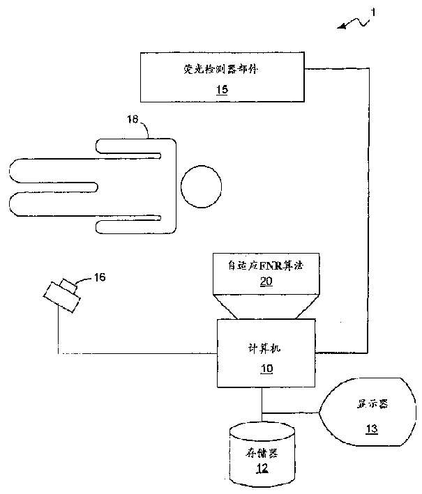
图1是说明本发明的X射线荧光系统的功能性方块图,该系统实施本发明的自适应FNR算法。本发明的X射线荧光系统1包括一个荧光X射线源16,它把X射线投射到病人18的身上,还包括一个荧光X射线检测器部件15,它检测投射于其上的X射线并产生荧光图象数据。系统1还包括一台对由荧光X射线检测器部件15产生的荧光图象数据进行处理的计算机10、存储器设备12和显示监视器13。Figure 1 is a functional block diagram illustrating an x-ray fluorescence system of the present invention implementing the adaptive FNR algorithm of the present invention. The
正如熟悉本技术的人们所理解的,本发明的自适应FNR算法20并不局限于针对利用自适应FNR算法20的那种类型的X射线荧光系统。熟悉本技术的人们还会理解,X射线荧光系统1也并不局限于任何特定的部件。例如,本技术中人们都知道,各种不同的荧光X射线检测器部件可以用来收集X射线并用来产生荧光X射线图象数据。人们还都知道,可以得到各种不同的荧光观察系统,它们都适合用于X射线荧光系统。As will be appreciated by those skilled in the art, the
荧光X射线检测器部件15最好包括一个数字平面型的X射线检测器。在本技术中数字平面X射线检测器是已知的。适合使用于本发明中的这种类型的检测器使用碘化铯闪烁器,它吸收X射线的光子并将它转为可见光。光被包含在检测器中的光敏二极管阵列转变成电能。检测器包括读出电子电路,它将在每个象素上的电子电荷转变成数字数据,后者适合于被计算机10进行图象处理。The fluorescent
但是,其它类型的检测器也适用于本发明。例如,图象增强器(未示出)接收X射线并将X射线转换成可见光子,然后光子再转换成为电模拟信号。这些电模拟信号可以再转换成适合于由计算机10处理的数字信号。However, other types of detectors are also suitable for use with the present invention. For example, an image intensifier (not shown) receives X-rays and converts the X-rays into visible photons, which are then converted into electrical analog signals. These electrical analog signals can be converted back into digital signals suitable for processing by
计算机10连接到荧光X射线源16和荧光X射线检测器部件15。计算机10控制由荧光X射线源16和荧光X射线检测器部件15合作实行的数据采集过程。计算机10可以和一个存储设备12相连,它可以用来存放程序和数据。计算机10最好还连接到显示监视器13以便在显示监视器13上能够显示按照自适应FNR算法20处理过的X射线图象数据。The
按照本发明的一个实施例,自适应FNR算法20是由软件实施的,该软件由计算机10执行。但是,熟悉本技术的人们将会理解,自适应FNR算法20可以仅仅用硬件来实现,也可以用硬件和软件的组合来实现。应该指出,计算机10并不局限于任何特定类型的计算机。如在这里所使用的这个术语,术语“计算机”的本意是指任何能够实现本发明的任务所需要而去执行运算或计算的机器。本质上,这包括任何机器,它能够接受结构化的输入并按照预定的规则处理这些输入以产生一个输出。因此,熟悉本技术的人们会理解,计算机10并不局限于任何特定的物理的、结构的或电气的配置。According to one embodiment of the present invention, the
图2是说明本发明的自适应FNR算法20的各种功能的流程图。如上所述,本发明的自适应FNR算法20评估噪扰统计值和预测所关心的对象的对比度。FNR算法20最好在区域性的或逐个象素基础上来修正噪扰评估和对比度预测。然后修正的噪扰评估和对比度被FNR算法所利用以便适应性地规定FNR算法20的运动检测的窗口和适应性地规定要在图象数据上实施的时间滤波的范围。如在这里所用的,“适应性地规定”及其类似的提法是指去改变那些对从背景上识别要被成象的对象进行控制的参数和改变那些针对时间滤波的范围的参数,这里将进一步说明。应该指出,没有必要在区域性的基础上修正对噪扰统计值的评估和对对象对比度的预测。FNR算法20能够在没有在区域性的基础上修正对噪扰统计值的评估和对对象对比度预测的情况下得到充分的实施。但是,如果它的参数是使用了在区域性的基础上修正的噪扰统计值评估和对象对比度预测而作了修正,那么FNR算法20将以更好的坚固性(鲁棒性)来实现(例如,提供改进了的对象识别程度和降低噪扰)。因此,本发明将按照一个实施例来说明,在该实施例中噪扰统计值评估和对象对比度预测是在区域性基础上修正的。FIG. 2 is a flowchart illustrating various functions of the
为了评估伴随着输入图象的噪扰统计值,首先要确定平均光子计数,如方块21所示。荧光X射线检测部件通常称作为平坦面板(平板),它具有有限的增益,这个增益是和平板的转换系数有关的。噪扰的数量是从和平均光子计数相伴随的电子数目来评估的,如方块23所示。有关与荧光X射线检测器部件15相伴随的噪扰统计值的确定方式将在下面对照图3作详细的讨论。In order to evaluate the noise statistics accompanying the input image, the average photon count is first determined, as shown in
一旦噪扰统计值被确定,就预测相关对象的对比度,如方块25所示。在实时荧光成象中,像印模或导引线这样的对象是在病人的身体中在由X射线荧光系统所成象的区域内操纵的。对象的对比度将取决于许多因素,包括对象的形状、大小和对象的组成。对象的对比度还取决于其它一些因素,包括病人的大小和荧光X射线检测器部件的特性、成象几何外形和X射线源。Once the noise statistics are determined, the contrast of the object of interest is predicted, as indicated by
通过把这些因素都考虑到之后,就可以产生一个模型,它将预测在一组给定的采集参数的情况下病人体内对象的对比度。熟悉本技术的人们会懂得产生这样一个模型的方式。因此,为了简明起见这里将不提供像印模这样的有关对象建模方式的详细讨论。By taking these factors into account, a model can be generated that will predict the contrast of objects in a patient for a given set of acquisition parameters. Those skilled in the art will understand the manner in which such a model can be generated. Therefore, for the sake of brevity, a detailed discussion of how objects like impressions are modeled will not be provided here.
还应该指出,对相关对象的对比度的预测这一步骤通常是以查找表(未示出)的形式实现的。要生成在X射线荧光显示中经常使用的各种不同对象的模型,并把有关对象的对比度的预测以及这些预测都存放在查找表中。在对病人实施X射线荧光显示之前,实施这一步骤的人员把有关对象的和病人的大小和体重的数据输入到X射线荧光显示系统1中。可能包括在例如存储设备12中的查找表就输出一个最小的对比度预测,这个预测是和由实施这一步骤的人员所输入的信息和系统的采集参数相关联的。It should also be noted that the step of predicting the contrast of the relevant object is usually implemented in the form of a look-up table (not shown). Models of the various objects commonly used in X-ray fluorescence display are generated and predictions about the contrast of the objects are stored in look-up tables. Before X-ray fluoroscopy is performed on the patient, the person performing this step enters into the
然后,这个对比度预测和噪扰统计值评估就在有必要的情况下去修正FNR参数,如方块27所示。然后FNR算法20就利用修正的FNR参数去实施降低荧光噪扰以修正运动检测窗口和所实施的时间滤波的范围,如方块29所示。和对象相关联的绝对对比度,在这里也称作灰度级差,以及噪扰统计值评估一般是以实时方式在区域的基础上被修正或更新,从而使FNR算法的参数能够在区域的基础上被修正。与对象相关联的灰度级差和噪扰统计值评估的在区域性基础上进行修正的方式将在下面参考图3和4加以讨论。This contrast prediction and noise statistics evaluation then modifies the FNR parameters if necessary, as shown in
在详细说明本发明的FNR算法20之前,将首先提供有关曝光管理(EM)参数和这些参数如何影响噪扰统计和对象对比度的方式的讨论。在一次X射线荧光显示期间,X射线由X射线源16以一个特定的帧速率照射,这个帧速率一般是在每秒5到30次这个范围之内。X射线用给定的峰值电压照射,这个电压通常为以KVp表示的若干千伏。X射线源16通常是以毫安级(mA)的电流来驱动。X射线荧光检测器部件15具有与它相关联的检测剂量,它的特性取决于X射线的频谱(即作为能量的函数的X射线光子的分布)、频谱滤波器、衰减途径、用来驱动X射线源16的电流,以及成象几何形状。Before detailing the
频谱滤波器一般由铜组成,铜能够过滤X射线。频谱滤波器(未示出)一般位于X光束途径中靠近X射线源16的地方。在数据采集期间,通过对X射线源16的X光管加上一定持续时间的脉冲而得到每一帧,这个持续时间通常称为X射线源16的脉冲宽度。脉冲宽度的典型值在1到20毫秒之间。源到象的距离(SID)和源到对象的距离(SOD)决定了对象的放大倍数。Spectral filters are generally composed of copper, which filters X-rays. A spectral filter (not shown) is typically located close to the
曝光管理(EM)参数包括了所有这些采集参数,即脉冲宽度、帧速率、X光管的峰值电压(KVp)、用于驱动X射线源16的电流、频谱滤波器以及检测器剂量。通常在X光束的途径中靠近X射线荧光检测器部件15的地方要放置一个栅网(未示出)。这个栅网减轻了由于散射的光子所引起的对比度的降低,但是也进一步衰减了X光束。非无限小的焦点束斑的大小减少了对比度,尤其是对于小尺寸的对象,这种减小和放大倍数有关。这些因素也是曝光管理的因素,它们应该在确定对象的对比度时加以考虑。对比度还和组成对象的材料高度相关。一般说来,由具有高原子序数的元素所构成的材料能更有效地吸收X射线的光子,因此会产生比起背景来更高的对比度。Exposure management (EM) parameters include all these acquisition parameters, namely pulse width, frame rate, peak voltage (KVp) of the X-ray tube, current used to drive the
所有这些因素都影响对象的对比度。这些因素中的某些因素也会影响图象数据中所包含的噪扰的数量。因此,这些参数也被用来评估噪扰的统计值和预测图象中对象的对比度。在评估噪扰统计值和预测对象对比度中如何考虑这些因素的影响的方式将参考图3和4而在这里加以讨论。All of these factors affect the contrast of an object. Some of these factors also affect the amount of noise contained in the image data. Therefore, these parameters are also used to evaluate the statistics of noise and predict the contrast of objects in the image. The manner in which the influence of these factors is taken into account in evaluating noise statistics and predicting object contrast will be discussed herein with reference to FIGS. 3 and 4 .
图3是从功能上说明为了评估噪扰统计值而实施的各个步骤的流程图。图3的流程图相当于由图2中方块23所代表的步骤。如上所述,X射线的频谱相当于作为与光子相关联的能量的函数的光子的分布,这种分布取决于峰值电压(KVp)、靶体材料和X光束与靶体所夹的角度。与荧光X射线检测器部件15相关联的X射线的频谱最好是在执行FNR算法20之前先行计算出存放在像存储设备12这样的存储器的文件中。在文件中存放着对于每一个峰值电压、靶体夹角和靶体材料的X射线频谱。在文件中存放的X射线频谱最好对应于驱动电流为1毫安(mA)的X射线源。FIG. 3 is a flowchart functionally illustrating the various steps performed to evaluate noise statistics. The flowchart of FIG. 3 corresponds to the steps represented by
为了得到与检测器部件15相关联的X射线频谱,FNR算法20从存放在存储器中的文件中获得对应于给定的峰值电压、靶体夹角和靶体材料的相应的频谱文件。然后要修正光通量以便将所用的任何频谱滤波器考虑进去,同时还要考虑与病人身体相关的滤波特性,如方块33所示。利用在典型的X射线荧光系统中正常会实施的大小预测器来预测通过病人的丙烯酸等价衰减值(就是说,用丙烯酸材料来模拟组织)。在实施这一步骤之前,在频谱文件中相关联的通量还要根据X光管的效率和实际所使用的电流值来定标。To obtain the X-ray spectrum associated with the
然后,根据X光管的内在滤波特性、频谱滤波器和丙烯酸等价病人的厚度进一步修正频谱文件,而且对在检测器上的X射线频谱的吸收进行建模,如方块35所示。一旦这些步骤都实现之后,就对平均的背景评估其噪扰统计值,这时还要考虑到检测器部件15的性质和与所用的X射线剂量相关联的电子噪扰的影响,如方块37所示。The spectral file is then further modified according to the intrinsic filtering properties of the X-ray tube, the spectral filter and the thickness of the acrylic equivalent patient, and the absorption of the X-ray spectrum at the detector is modeled, as shown in block 35 . Once these steps have been accomplished, the noise statistics are evaluated for the averaged background, taking into account the nature of the
为了评估噪扰统计值,要通过将散射的和主要的成分两者合并起来而计算对应于修正了的X射线频谱的每个象素的光子数。然后计算所得到的修正过的X射线频谱的“斯旺克因子”(“Swank Factor”)。术语“斯旺克因子”在文献中是众所周知的,它是因为在闪烁器中进行转换过程的X射线有非单一能量的特性而得来的。利用在步骤35中所产生的对修正的X射线频谱的吸收模型,通过确定与吸收模型相关联的光子数量和通过预测光子变成电子的转换,在次象素的基础上计算对于所产生的背景的积聚在检测器部件15上的能量。To evaluate the noise statistics, the number of photons per pixel corresponding to the corrected X-ray spectrum is calculated by combining both the scattered and dominant components. The "Swank Factor" of the resulting corrected X-ray spectrum is then calculated. The term "Swank factor" is well known in the literature and is derived from the non-single-energy nature of the X-rays undergoing the conversion process in scintillators. Using the absorption model for the corrected X-ray spectrum generated in step 35, by determining the number of photons associated with the absorption model and by predicting the conversion of photons into electrons, the calculation for the generated The energy of the background accumulated on the
一旦光子已经转变成为电子,在考虑到由于闪烁器的平滑作用而导致的任何噪扰的降低,就可评估与电子相关联的噪扰统计值。在评估了噪扰统计值之后,就利用区域性的平均值来对噪扰统计值进行定标,这个区域性的平均值是利用按照本发明的FNR算法20经过降低噪扰后的图象帧计算而得的,如方块39所示。区域性的平均值可以很简单地通过对最靠近降噪过的图象帧中有关象素相邻的一群象素取平均值而获得。因此,噪扰统计值的评估是在区域性的基础上利用这个区域平均值而修正的。Once the photons have been converted to electrons, the noise statistics associated with the electrons can be evaluated, taking into account any noise reduction due to the smoothing effect of the scintillator. After evaluating the noise statistics, the noise statistics are scaled using the regional average value of the image frame after the noise reduction using the
熟悉本技术的人将会理解,上面所讨论的在评估噪扰统计值中所实施的各步是优选的,但对于本发明来说并不是必需的。熟悉本技术的人们将会理解上面所讨论的为了评估噪扰的过程所用的方式可以通过消除或修改某些步骤而变化。选择上面参考图3所讨论的用来评估噪扰统计值的步骤的特定组合是因为它优化了本发明的自适应FNR算法的性能。熟悉本技术的人们将会理解这些参数可以用于评估噪扰统计值中的方式。Those skilled in the art will appreciate that the steps discussed above performed in evaluating noise statistics are preferred, but not required to the present invention. Those skilled in the art will appreciate that the manner in which the procedures for evaluating noise discussed above may be varied by eliminating or modifying certain steps. The particular combination of steps discussed above with reference to Figure 3 for evaluating noise statistics was chosen because it optimizes the performance of the adaptive FNR algorithm of the present invention. Those skilled in the art will understand the manner in which these parameters can be used in evaluating noise statistics.
在评估了噪扰统计值之后,相关对象的对比度就可进行预测,这个对象可以是举例而言一个印模。不过,这些步骤不一定要按上述次序进行;对比度预测可以在评估噪扰统计值之前得到。图4是说明由本发明的自适应FNR算法20在预测相关对象的对比度时所执行的各个步骤的流程图。图4的流程图对应于图2中方块25所代表的步骤。预测相关对象的对比度的过程最好在对病人实施荧光X射线过程之前实现。因此,各种不同的相关对象的对比度最好是事先计算并存放在存储器中(例如一个查找表),而存储器可以是存储设备12。实时的散射评估是在过程期间得到的,它用于更新事先计算的对象对比度。After evaluating the noise statistics, the contrast of the relevant object, eg an impression, can be predicted. However, these steps do not have to be performed in the above order; the contrast prediction can be obtained before evaluating the noise statistics. FIG. 4 is a flowchart illustrating the various steps performed by the
应该指出,这里所用的术语“对比度”是指有关对象的灰度级强度和背景的强度之间的差别,并把该差别除以背景的强度。换句话说,如果背景强度用变量A来表示,而对象的强度用变量B来表示,则对比度定义为(A-B)/A。如上所述,对比度或强度差别是预测的或预先计算的。然后通过评估区域性的平均值,预测的强度差别在区域的基础上也就是在逐个象素的基础上被更新。为了将最好是预先计算好的预测的对比度和利用区域均值修正以后的对象对比度区别开来,在这里将把前者简单地称之为“对比度”,而后者在这里将称之为“绝对对比度”。It should be noted that the term "contrast" as used herein refers to the difference between the gray level intensity of the object concerned and the intensity of the background, and this difference is divided by the intensity of the background. In other words, if the intensity of the background is represented by variable A and the intensity of the object is represented by variable B, then the contrast ratio is defined as (A-B)/A. As mentioned above, the contrast or intensity difference is predicted or pre-calculated. The predicted intensity difference is then updated on a regional basis, ie on a pixel-by-pixel basis, by evaluating the regional average. In order to distinguish the contrast, which is preferably precomputed, from the contrast of the object corrected by the area mean, the former will be referred to here simply as "contrast", while the latter will be referred to here as "absolute contrast". ".
当选择了一个特定的记录时,即当选定了X射线的参数和相关的对象后,查找表就输出与该选定对象相关联的对比度预测。然后该预测就在对病人实施的X射线处理期间由本发明的自适应FNR算法20所使用。采集参数最好被用来得到查找表的地址。对比度预测被自适应FNR算法20所使用的方式将在下面参考图5而详细讨论。When a particular record is selected, ie when the X-ray parameters and associated object are selected, the look-up table outputs the contrast prediction associated with the selected object. This prediction is then used by the
预测相关对象的对比度的第一步是产生X射线的频谱,如方块41所示。这一步骤和图3中的方块31所表示的步骤基本上相同。在X射线频谱产生之后,就将在检测器上产生图象背景,如方块43所示。在这一步中,自适应FNR算法20使用上面讨论过的病人的大小预测器来预测通过病人的丙烯酸等值衰减。通过根据检测器部件15的闪烁器材料和可见光子的产生而对修正的X射线频谱的吸收所作的建模,并通过可见光子转换成电子的预测,在次象素的基础上对背景来计算积聚在检测器部件15上的能量。然后再考虑到这样一些因素,如与成象几何相关联的散射光和主要光的影响、病人的厚度以及栅网的性能等来获得最后的图象背景。The first step in predicting the contrast of an object of interest is to generate a spectrum of X-rays, as shown in block 41 . This step is basically the same as the step represented by block 31 in FIG. 3 . After the X-ray spectrum is generated, an image background will be generated on the detector, as shown in block 43 . In this step, the
在检测器上产生图象背景之后,产生对象的轮廓,如方块45所示。相关对象的形状和相关对象的组成是已知的。在给定的过程中要使用的医疗记录也是已知的,例如当选择了带有导引线的介入型荧光显示记录时,要优化的对象一般就是直径为0.014英寸的导引线。另一方面,对于诊断型导管化记录,要优化的对象则是引导用的导管。另一种医疗记录类型的例子是对比注入过程。在这种类型的过程中,相关的对象是预定直径的动脉,其中充满了对比材料。After the image background is generated on the detector, the outline of the object is generated, as shown in block 45 . The shapes of the related objects and the composition of the related objects are known. The medical record to be used in a given procedure is also known, for example when an interventional fluoroscopic record with a guide wire is selected, the object to be optimized is typically a guide wire with a diameter of 0.014 inches. On the other hand, for diagnostic catheterized recordings, the object of optimization is the guiding catheter. Another example of a type of medical record is a contrast injection procedure. In this type of procedure, the object of interest is an artery of predetermined diameter filled with contrast material.
由于相关对象的形状和特性是已知的,因此X射线束会遇到的衰减途径就可以产生。只要相关对象的形状和特性是已知的,而且要使用的医疗记录和与其相关的采集参数是已知的,那么了解本技术的人就懂得能够产生这样的一条衰减途径的方式。因此,对于一个具体的相关对象产生这样一条衰减途径的方式的详细讨论为了简单起见将不在这里提供。Since the shape and properties of the object of interest are known, the attenuation path that the x-ray beam will encounter can be generated. Those skilled in the art will appreciate the manner in which such an attenuation path can be produced, provided that the shape and properties of the object of interest are known, and the medical records to be used and the acquisition parameters associated therewith are known. Therefore, a detailed discussion of the manner in which such an attenuation pathway is generated for a specific object of interest will not be provided here for the sake of simplicity.
然后利用源到象的距离(SID)和源到对象的距离(SOD)之比来得到相应的几何放大倍数。相关对象的投影图象就利用所得到的几何放大而生成。这是产生对象轮廓的最后一步。一旦产生了对象的轮廓,对象在检测器部件15上的投影就可产生,如方块47所示。Then use the source-to-image distance (SID) and the source-to-object distance (SOD) ratio to get the corresponding geometric magnification. A projected image of the object of interest is then generated using the resulting geometric magnification. This is the last step in generating the outline of the object. Once the outline of the object has been generated, a projection of the object onto the
在产生在检测器部件15上的对象投影时,上面所讨论的病人大小预测器被用来预测通过病人的丙烯酸等值衰减。然后根据病人的等值丙烯酸厚度来修改与修正过的X射线频谱相关联的X射线通量。然后这个修改过的X射线通量被用来产生放大对象的投影。The patient size predictor discussed above is used to predict the acrylic equivalent attenuation through the patient when the object projection is produced on the
然后,通过对修正后的X射线频谱在相应的检测器部件15的闪烁材料上的吸收的建模,所产生的可见光子的数量、和可见光子变成电子的转换,可以在次象素的基础上计算相关对象在检测器部件15上积聚的能量。然后合成图象上的所有各点都被背景所取代,这个背景是由方块43所表示的步骤在不存在对象的地方获得的。然后根据检测器部件15的调制转移函数(MTF)来修改投影,这个函数对于给定的荧光检测器部件来说一般都是已知的。Then, by modeling the absorption of the corrected X-ray spectrum on the scintillation material of the
通过考虑有限聚焦束斑的模糊性,投影要作进一步的修正。然后根据由成象几何尺寸、气隙、视场、病人厚度和栅网性能进行建模所得的散射的及主要的分量对投影进行修改。再把荧光显示系统1的固有的时间延迟考虑进去以得到在检测器部件15上的最后的对象投影。熟悉本技术的人们会懂得利用这些参数以预测相关对象的对比度的方式。The projection is further corrected by taking into account the ambiguity of the finite focused beam spot. The projection is then modified according to the diffuse and principal components modeled by imaging geometry, air gap, field of view, patient thickness, and grid properties. The inherent time delay of the
在对象的对比度得到预测之后,随着图象帧的采集,对比度以实时方式在区域性基础上逐个象素地被定标以便产生由对象产生的灰度级差或绝对对比度。图4中的方块49和51分别表示区域均值的计算和根据区域均值所作的对象对比度的定标。After the object's contrast is predicted, as image frames are acquired, the contrast is scaled pixel by pixel on a regional basis in real-time to produce the gray level difference or absolute contrast produced by the object. Blocks 49 and 51 in FIG. 4 represent the calculation of the area mean and the scaling of object contrast based on the area mean, respectively.
就像熟悉本技术的人们所理解的,上面所讨论的在预测相关对象的对比度中所实施的许多步骤是可以省略或修改的。熟悉本技术的人们知道,对于本发明许多这样的步骤是可取的但并不是必需的。上面所讨论的用于预测对象对比度的各个步骤的组合是可取的,因为它优化了本发明的自适应FNR算法20的性能。熟悉本技术的人们会理解为了修改本发明的自适应FNR算法20而修改或干脆省略某些步骤的方式。熟悉本技术的人们也会懂得所有这些对本发明的自适应FNR算法20的修改是在本发明的范围之内的。As will be appreciated by those skilled in the art, many of the steps discussed above performed in predicting the contrast of an object of interest can be omitted or modified. Those skilled in the art recognize that many of these steps are desirable but not necessary for the present invention. The combination of the steps discussed above for predicting object contrast is desirable because it optimizes the performance of the
如上面针对图2所述,一旦评估了噪扰统计值并预测了相关对象的对比度后,评估的噪扰统计值和预测的对比度就在区域基础上加以修正以得到区域性的评估的噪扰统计值和与对象相关联的区域性的绝对对比度。修正的噪扰统计值和对比度用于适应性地改变FNR算法20的参数。然后通过利用修正的参数,如有需要,去改变运动检测的窗口和在图象上实施的时间滤波的范围来实施降低荧光显示噪扰。这些功能的实施方式将在下面参考图5而说明。As described above for Figure 2, once the noise statistics are estimated and the contrast of the object of interest is predicted, the estimated noise statistics and predicted contrast are corrected on a regional basis to obtain regional estimated noise Absolute contrast between the statistical value and the culture associated with the object. The modified noise statistics and contrast are used to adaptively change the parameters of the
图5是说明按照优选实施例的本发明的自适应FNR算法20的各个功能部件的方块图。方块47表示运动辨识过程而方块53表示噪扰降低过程。这些方块以及方块43、45和51将在下面详细讨论。但是,在详细讨论所有这些方块之前,先提供关于如何获得方块51中所示的变量A1和A2的方式的讨论。FIG. 5 is a block diagram illustrating the various functional components of the
在得到了修正的噪扰统计值和绝对对比度之后,这些变量被用来修正FNR算法20。按照本发明的优选实施例,降低荧光噪扰是按照下列等式进行的:These variables are used to modify the
Yi(n)=f1(Δ,NOISE,CONTRAST,STRENGTH,EM)*Xi(n)+(1-f1)*f2(Yiir(n),X-bar(n),Y-bar(n-1),EM),(式1)Yi(n)=f1(Δ, NOISE, CONTRAST, STRENGTH, EM)*Xi(n)+(1-f1)*f2(Yiir(n), X-bar(n), Y-bar(n-1 ), EM), (Equation 1)
这里Yi(n)表示在当前的帧n中当前象素i的输出值,而Xi(n)表示当前帧n中当前象素i的输入值。变量Δ表示在低通滤波过的帧n中的象素i的输入值和在低通滤波过的输出帧n-1中的同一个象素的输出值之间的差,该n-1帧相当于前一帧。因此,变量Δ可表示为X_bari(n)-Y_bari(n-1)。Here Yi(n) represents the output value of the current pixel i in the current frame n, and Xi(n) represents the input value of the current pixel i in the current frame n. The variable Δ represents the difference between the input value of pixel i in low-pass filtered frame n and the output value of the same pixel in low-pass filtered output frame n-1, which Equivalent to the previous frame. Therefore, the variable Δ can be expressed as X_bari(n)-Y_bari(n-1).
变量EM表示曝光管理轨迹参数,而变量STRENGTH表示滤波器的基线强度,后者最好由用户选定。参数NOISE和CONTRAST分别表示修正的噪扰统计估值和修正的对象绝对对比度,它们是以上面参考图1-4所讨论的方式得到的。变量Yiir(n)表示不存在任何运动检测的情况下按时间平均的响应。它是由简单的递归等式按时间取平均值的,即Yiir(n)=A1*Yiir(n-1)+(1-A1)*X(n)。变量A1将在下面详细讨论。The variable EM represents the exposure management track parameter, while the variable STRENGTH represents the baseline strength of the filter, the latter preferably being selected by the user. The parameters NOISE and CONTRAST denote respectively the corrected noise statistical estimate and the corrected object absolute contrast obtained in the manner discussed above with reference to FIGS. 1-4. The variable Yiir(n) represents the time-averaged response in the absence of any motion detection. It is averaged over time by a simple recursive equation, namely Yiir(n)=A1*Yiir(n-1)+(1-A1)*X(n). Variable A1 will be discussed in detail below.
函数f1乘以Xi(n),这相当于在帧n中的输入象素i的值。这个函数确定了包含在帧n中的象素i的输出值中帧n的输入象素i的值的百分比,这里象素i的输出值由Yi(n)表示。在等式1中可以看到,在确定在象素i输出值中所包含的输入象素i值的数量中区域的噪扰统计值评估和区域的对比度预测都已被考虑在内。换句话说,在确定要在输入象素上实施的时间滤波的范围时区域的噪扰评估和区域的对比度预测是被考虑在内的。在确定要在输入象素上实施的时间滤波的范围时曝光管理(EM)参数也是预以考虑的。Function f1 multiplies Xi(n), which corresponds to the value of input pixel i in frame n. This function determines the percentage of the value of input pixel i of frame n contained in the output value of pixel i in frame n, where the output value of pixel i is denoted by Yi(n). As can be seen in
函数f2通常表示经过时间滤波也就是经过降噪的过去的输入图象和过去的输出图象的某些组合。因此,帧n的象素i的输出值保留着一定百分比的在象素i的输出值Yi(n)中的这些过去已滤波的值。The function f2 generally represents some combination of temporally filtered, ie denoised, past input images and past output images. Thus, the output value of pixel i for frame n retains a certain percentage of these past filtered values in the output value Yi(n) of pixel i.
因此,函数f1和f2以一种类似于比例增减(滑动比例)的方式工作,也就是当运动存在时,在象素i的输出值中包含着更多或全部的象素i的输入值而较少的或没有经时间滤波的图象。相反,当运动不存在时,在象素i的输出值中包含着较少的象素i的输入值而更多的经时间滤波的图象。Therefore, functions f1 and f2 work in a manner similar to scaling (sliding scale), that is, when motion exists, the output value of pixel i contains more or all of the input value of pixel i and fewer or no temporally filtered images. Conversely, when motion is absent, less of the input value of pixel i and more of the temporally filtered image is contained in the output value of pixel i.
等式1可以改写成如下方式:
Yi(n)=f1(Δ,A2,STRENGTH,EM)*Xi(n)+(1-f1)*f2(Yiir(n),X_bar(n),Y_bar(n-1),EM),(式2)Yi(n)=f1(Δ, A2, STRENGTH, EM)*Xi(n)+(1-f1)*f2(Yiir(n), X_bar(n), Y_bar(n-1), EM), ( Formula 2)
变量A2是从按区域修正的噪扰统计评估和绝对对比度预测获得的。因此,在等式1中所表示的NOISE和CONTRAST预测变量在等式2中用变量A2来取代。虽然由于A2是和噪扰统计值评估及对象对比度预测是相关的这一事实而使变量A2已考虑到了EM参数,但在等式2中,EM仍然作为独立的变量而出现。这为下列情况提供了灵活性,那就是f1可以通过允许将EM参数的改变分解到等式2中来实施而不需要A2值的改变。Variable A2 was obtained from region-corrected statistical evaluations of noise and absolute contrast predictions. Therefore, the NOISE and CONTRAST predictors represented in
变量A2的作用是作为在输入图象中检测运动所用的阈值。变量A2的值要根据按区域修正的噪扰统计值评估和对象绝对对比度预测而修正。因此,变量A2的值是在区域性基础上修正的。通过在区域性的基础上自适应地改变变量A2的值,FNR算法20的运动识别窗口也是在区域的基础上修正的。Variable A2 acts as the threshold used to detect motion in the input image. The value of variable A2 is corrected based on the evaluation of the area-corrected noise statistics and the prediction of the absolute contrast of the object. Therefore, the value of variable A2 is corrected on a regional basis. By adaptively changing the value of variable A2 on a regional basis, the motion recognition window of the
变量A2的值和Δ的值相比较以确定函数f1的值。具体地说,当Δ小于A2的值时,FNR算法20就作出确定,即不存在运动,等式2可以这样改变,即函数f1可以直接设置成等于变量A1的值。函数f2则设置成等于Yi(n-1),它是在前面的帧中象素i的输出值。The value of variable A2 is compared with the value of Δ to determine the value of function f1. Specifically, when Δ is less than the value of A2, the
当Δ小于A2的值时,函数f1和f2可表示为:When Δ is less than the value of A2, the functions f1 and f2 can be expressed as:
f1(Δ,A2)=A1 (式3)f1(Δ, A2)=A1 (Formula 3)
f2=Yi(n-1) (式4)f2=Yi(n-1) (Formula 4)
因此,等式1可以重新写成:Therefore,
Yi(n)=A1*Xi(n)+(1-A1)*Yi(n-1) (式5)Yi(n)=A1*Xi(n)+(1-A1)*Yi(n-1) (Formula 5)
当Δ大于A2的值时,函数f1设置成等于1且输出象素的值就被赋以输入象素的值而不实施时间滤波。应该指出,如在等式1和2中所表达的函数f2,比起在等式4中所给出的这一函数的表达式而言,是这一函数更为通用的表达式。在等式1和2中所表达的函数f2允许保留在FNR过程的输出中的过去图象数据的类型是可以极大地变化的,这将提高对FNR过程进行优化的能力。When Δ is greater than the value of A2, the function f1 is set equal to 1 and the value of the output pixel is assigned the value of the input pixel without temporal filtering. It should be noted that the function f2 as expressed in
变量A1的值最好是根据Δ和变量A2之间的差值来变化。当Δ远小于变量A2的值时,输入象素明显地是在运动识别窗口之外。因此,在这种情况下,在输入象素上所实施的时间滤波的范围将比较大。相反,当Δ只是略小于变量A2的值时,这个差值表明在有运动的区域和无运动的区域之间的图象中的一个边界。在这个区域内,在输入象素上实施的时间滤波将是较小的。The value of variable A1 is preferably varied according to the difference between Δ and variable A2. When Δ is much smaller than the value of variable A2, the input pixel is clearly outside the motion recognition window. Therefore, in this case, the extent of the temporal filtering performed on the input pixels will be relatively large. Conversely, when Δ is only slightly smaller than the value of variable A2, the difference indicates a boundary in the image between areas with motion and areas without motion. In this region, the temporal filtering performed on the input pixels will be small.
因此,为了实施运动识别,FNR算法20所利用的分界机制是非线性的,因为当Δ小于变量A2的值时,Δ和变量A2的值之间的差值的大小决定了要实施的时间滤波的范围。但是,不仅仅分界机制是非线性的,而且它还是在区域性基础上可修正的,这导致了运动识别窗口和所实施的时间滤波的范围也是在区域性的基础上可修正的。NFR算法20的这种总体的可修正性允许对荧光显示噪扰降低进行优化并且可以在逐个象素和逐帧基础上进行动态修正。熟悉本技术的人们会懂得提供能够以这种方式进行修正的FNR算法的优点。Therefore, in order to implement motion recognition, the demarcation mechanism utilized by the
如上所述,图5是说明本发明的自适应FNR算法20的功能部件的方块图。方块47表明运动检测过程,在此过程中FNR算法20确定输入象素是否对应着图象帧中的运动。方块53表示当作出了输入象素是对应着运动的决定时所进行的降噪过程。方块43和45分别表示在区域的基础上评估噪扰统计值的过程和在区域的基础上预测相关对象的绝对对比度的过程。方块51表示利用修正的噪扰统计值的评估和修正的绝对对比度去相应地修正参数A1和A2。As noted above, FIG. 5 is a block diagram illustrating the functional components of the
从方块51指向方块47和53的箭头表明,在降低噪扰过程期间使用了参数A1和在运动识别过程期间使用了参数A2,如上面参考了等式所说明的那样。参数A2用来修改参数A1,然后它被用来按上面参考等式5所说明的方式实施噪扰降低。Arrows from block 51 to blocks 47 and 53 indicate that parameter A1 is used during the noise reduction process and parameter A2 is used during the motion recognition process, as explained above with reference to the equations. Parameter A2 is used to modify parameter A1, which is then used to implement noise reduction in the manner explained above with reference to Equation 5.
系统的数学建模可以用来作为对修正的参数规定其设置的一种手段。当EM参数或病人的特性变动时,其它的系统参数通过考虑系统模型而从它们的正常工作值被修改以便在X射线成象过程中保持相类似的质量。Mathematical modeling of the system can be used as a means of specifying the settings for the modified parameters. When EM parameters or patient characteristics vary, other system parameters are modified from their normal operating values by taking into account the system model in order to maintain similar quality during X-ray imaging.
例如,一个EM参数帧采集速率的改变可能是需要的以便服从规定的剂量限制。不同的帧速率会影响可见的图象质量。本发明的FNR算法可以被修正以包括一个时间适应特性来考虑到过程的时间特性(如在这里所用“适应于“及其类似的措词指的是把算法编程或嵌入到计算机或芯片中以便根据算法所希望的用处来处理数据)。通过考虑整个系统的时间模型,可以导出一个修正FNR参数的方法以便在该“系统”中提供相同的成象性能。这个“系统”被说成是包括X射线源、对象/背景、X射线检测器、处理过程、监视器、以及人类观察者。为了说明的目的,提出了系统的一个简单的模型。对于包含低延迟的检测器平板和短持续时间的X射线脉冲以便在对象运动时导致产生可忽略的模糊化的系统来说,对系统的时间频率响应起主要影响的因素如下所示:For example, a change in the frame acquisition rate of an EM parameter may be required in order to comply with a prescribed dose limit. Different frame rates affect the perceived image quality. The FNR algorithm of the present invention can be modified to include a time adaptation feature to take into account the time characteristics of the process (as used herein, "adapted to" and similar expressions refer to programming or embedding the algorithm into a computer or chip so that process the data according to the intended use of the algorithm). By considering the time model of the entire system, a method of modifying the FNR parameters can be derived to provide the same imaging performance in the "system". This "system" is said to include the X-ray source, object/background, X-ray detector, process, monitor, and human observer. For illustration purposes, a simple model of the system is presented. For a system that includes a low-latency detector panel and short-duration X-ray pulses to cause negligible blurring when the object is in motion, the factors that dominate the time-frequency response of the system are as follows:
帧采集/显示:假定瞬时的图象采样和在帧速率FR下的持续显示,则频率响应为:Frame acquisition/display: Assuming instantaneous image sampling and continuous display at frame rate FR , the frequency response is:
Hfps(f)=Sin(πf/FR)/(πf/FR)。H fps (f)=Sin(πf/F R )/(πf/F R ).
FNR处理:使用基于等式5的简化模型的递归FNR,这里允许A1的值根据改变着的帧速率而改变。将象素n的滤波器输出重新表述为Yn=A2X2+(1-A1)Yn-1,则滤波器的转移函数可按下式计算:HFNR(f)=A1/(1-[1-A1]e-j2πr)。人类观察者;观察者是用对周期Tint=0.1秒的理想积分而建模的:FNR processing: Use recursive FNR based on the simplified model of Equation 5, where the value of A1 is allowed to change according to the changing frame rate. Reexpress the filter output of pixel n as Y n =A 2 X 2 +(1-A 1 )Y n-1 , then the transfer function of the filter can be calculated as follows: H FNR (f)=A 1 /(1-[1-A 1 ]e -j2πr ). A human observer; the observer is modeled with an ideal integral over a period T int = 0.1 seconds:
Heye(f)=Sin(πfTint)/(πfTint)H eye (f)=Sin(πfT int )/(πfT int )
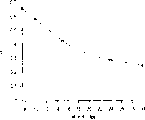
因此,系统在时间频率域内是由三个主要的(线性)分量所表示的,即Haystem(f)=Hfps(f)HFNR(f)Heye(f)。A1的综合是通过将频谱和参照情况下的频谱相匹配(例如,在最小二乘方的意义上、观察,等)而完成的。作为一个例子,考虑一个参照场合其操作为30fps,FNR值A1=0.24。图6和7提供了A1综合(观察匹配)的两个例子。图6在曲线610上提供了30fps采样率的模型的响应数据(dB);对于相应的f1值在15fps采样率时的相对应的模型数据则示于曲线620。与此相似,在图7中,对于所示值的30fps采样率的建模数据示于曲线710,而在曲线720则是7.5fps采样率的数据。在图6和7中分别使用了迭代值A1=0.42和0.66以便匹配这两个系统,大部分信息就存在于其中(能量含量主要在7赫及以下)。Thus, the system is represented in the time-frequency domain by three main (linear) components, Haystem (f)=H fps (f)H FNR (f)H eye (f). The synthesis of A 1 is done by matching the spectrum to that of the reference case (eg, in a least squares sense, observation, etc.). As an example, consider a reference scenario operating at 30 fps with an FNR value A 1 =0.24. Figures 6 and 7 provide two examples of A1 synthesis (observation matching). Figure 6 provides on curve 610 the response data (dB) of the model at a sampling rate of 30 fps; Similarly, in FIG. 7 , the modeled data for the 30 fps sampling rate is shown at curve 710 for the values shown, while the 7.5 fps sampling rate data is at curve 720 . Iteration values A 1 =0.42 and 0.66 were used in Figures 6 and 7 respectively in order to match the two systems where most of the information is present (energy content mainly at 7 Hz and below).
对于不同的帧速率重复上述方法并收集优化的A1值就产生了图8所示的曲线。曲线规定了对于任意帧速率的A1设置值以产生恒定的相对于70fps和A1=0.24标准的成象性能。一般说来,随着帧速率降低,A1要增加。Repeating the above method for different frame rates and collecting optimized A 1 values yields the curve shown in FIG. 8 . The curve specifies the A1 setting for an arbitrary frame rate to produce constant imaging performance relative to the 70 fps and A1 = 0.24 norm. Generally speaking, as the frame rate decreases, A1 should increase.
应该指出,本发明是参考特定的实施例而说明的,但是本发明并不局限于这些特定的实施例。熟悉本技术的人们会理解,对上面讨论的实施例可以作出许多变动和修改而所有这些变动和修改是在本发明的范围之内的。例如,熟悉本技术的人们会理解,上面讨论的函数f1和f2可以用各种不同方式来实现。熟悉本技术的人们也会懂得,参考各等式而在上面讨论的各参数和变量也并不是非有不可的。It should be noted that the invention has been described with reference to specific embodiments, but the invention is not limited to these specific embodiments. Those skilled in the art will appreciate that many variations and modifications may be made to the above-discussed embodiments and all such variations and modifications are within the scope of the invention. For example, those skilled in the art will appreciate that the functions f1 and f2 discussed above can be implemented in a variety of different ways. Those skilled in the art will also appreciate that the parameters and variables discussed above with reference to the equations are also not mandatory.
例如,尽管函数f2被说明是取决于各种不同的当前和过去的经滤波的图象帧的,但这只是为了表明f2的优选的相关性而不是要说明函数f2的唯一可能的相关性。最好是用过去和当前的经滤波的图象数据来产生f2,因为这些图是已经经过了降噪的。函数f2可以直接以前面的帧的经滤波的输出象素Yi(n-1)为基础。熟悉本技术的人们将理解,许多对上面等式的这种变动都可以在不偏离本发明的精神和范围的情况下作出。For example, although function f2 is shown as being dependent on various current and past filtered image frames, this is only to show the preferred dependencies of f2 and not to illustrate the only possible dependencies of function f2. It is best to use past and current filtered image data to generate f2 since these images have been denoised. The function f2 can be based directly on the filtered output pixel Yi(n-1) of the previous frame. Those skilled in the art will appreciate that many such variations to the above equations can be made without departing from the spirit and scope of the invention.
因此,函数f1和f2,以及变量A2,并不局限于任何特定的函数,而一般情况下,将由各种不同的能优化FNR过程的通用规则所定义。例如,下列规则将作用于函数f1的特性。随着某一区域的灰度级别强度的降低,函数f1从基线值降低,这个值是区域性统计值的函数。当强度增加时,函数f1降低。当X射线管的功率趋于它的极限时,f1从它的基线值降低。当Δ增加时,f1增加而且对于大于或等于A2的值它趋近于1。当脉冲宽度增大时,f1增大。当噪扰增加时,f1减小。当对病人的剂量趋近于规定极限时,f1减小。Thus, the functions f1 and f2, as well as the variable A2, are not restricted to any particular function, but will generally be defined by various general rules that optimize the FNR process. For example, the following rules will act on the properties of function f1. As the gray level intensity of a region decreases, the function f1 decreases from the baseline value, which is a function of the regional statistics. As the intensity increases, the function f1 decreases. As the power of the X-ray tube approaches its limit, f1 decreases from its baseline value. As Δ increases, f1 increases and it approaches 1 for values greater than or equal to A2. When the pulse width increases, f1 increases. When noise increases, f1 decreases. f1 decreases as the dose to the patient approaches the prescribed limit.
对于函数f2来说,这个函数最好被规定为它的各个变量的线性组合,尽管这并非是必须这样的。一般说来,当X射线管的功率趋向于它的极限时,由FNR算法20使用来实施低通滤波的空间和时间滤波器的强度增加。对于变量A2而言,当强度降低时,A2从基线值降低。当强度增加时,A2增加。当X射线管的功率增加时,A2从基线值增加。当脉冲宽度增加时,A2保持不变或减少。当对比度减少时,A2减少。当对比度增加时,A2增加。For function f2, this function is preferably specified as a linear combination of its variables, although this does not have to be the case. In general, the strength of the spatial and temporal filters used by the
熟悉本技术的人们将理解,可以实现许多函数,它们都适合于以总体上与这些规则相一致的方式来动态地修正本发明的FNR算法20。熟悉本技术的人们会懂得,别的修改和变动也可实施于本发明,它们都是在本发明的范围之内的。Those skilled in the art will understand that many functions can be implemented which are suitable for dynamically modifying the
Claims (16)
Applications Claiming Priority (2)
| Application Number | Priority Date | Filing Date | Title |
|---|---|---|---|
| US09/465,313 US6314160B1 (en) | 1999-12-17 | 1999-12-17 | Method and apparatus for performing fluoroscopic noise reduction |
| US09/465313 | 1999-12-17 |
Publications (2)
| Publication Number | Publication Date |
|---|---|
| CN1301025A CN1301025A (en) | 2001-06-27 |
| CN1151663C true CN1151663C (en) | 2004-05-26 |
Family
ID=23847291
Family Applications (1)
| Application Number | Title | Priority Date | Filing Date |
|---|---|---|---|
| CNB001356720A Expired - Fee Related CN1151663C (en) | 1999-12-17 | 2000-12-18 | Implementation of Adaptive Noise Reduction Method and X-ray Fluorescence System |
Country Status (4)
| Country | Link |
|---|---|
| US (1) | US6314160B1 (en) |
| EP (1) | EP1109401A3 (en) |
| JP (1) | JP2001238869A (en) |
| CN (1) | CN1151663C (en) |
Families Citing this family (30)
| Publication number | Priority date | Publication date | Assignee | Title |
|---|---|---|---|---|
| US6583420B1 (en) * | 2000-06-07 | 2003-06-24 | Robert S. Nelson | Device and system for improved imaging in nuclear medicine and mammography |
| US7054500B1 (en) * | 2000-12-06 | 2006-05-30 | Realnetworks, Inc. | Video compression and decompression system with postfilter to filter coding artifacts |
| FI113897B (en) * | 2001-11-23 | 2004-06-30 | Planmed Oy | Automatic exposure procedure and automatic exposure system |
| FR2846504B1 (en) * | 2002-10-29 | 2005-04-08 | Ge Med Sys Global Tech Co Llc | METHOD FOR DETERMINING FLUOROSCOPIC NOISE |
| US7135686B1 (en) | 2002-11-19 | 2006-11-14 | Grady John K | Low noise x-ray detector for fluoroscopy |
| US6879660B2 (en) * | 2002-12-18 | 2005-04-12 | General Electric Company | Method and apparatus for reducing spectrally-sensitive artifacts |
| JP3992651B2 (en) * | 2003-06-19 | 2007-10-17 | ジーイー・メディカル・システムズ・グローバル・テクノロジー・カンパニー・エルエルシー | Operation console, fluoroscopic imaging apparatus, and control method and system thereof |
| US7590306B2 (en) * | 2003-11-26 | 2009-09-15 | Ge Medical Systems Global Technology Company, Llc | Resolution adaptive image filtering system and method |
| US20060065844A1 (en) * | 2004-09-30 | 2006-03-30 | Zelakiewicz Scott S | Systems and methods for dynamic optimization of image |
| FR2884948B1 (en) * | 2005-04-26 | 2009-01-23 | Gen Electric | METHOD AND DEVICE FOR REDUCING NOISE IN A SEQUENCE OF FLUOROSCOPIC IMAGES |
| CN101658027B (en) * | 2007-03-31 | 2013-04-10 | 索尼德国有限责任公司 | Noise reduction method and unit for an image frame |
| US8825138B2 (en) * | 2007-09-17 | 2014-09-02 | Wisconsin Alumni Research Foundation | Method for reducing motion artifacts in highly constrained medical images |
| US20090086911A1 (en) * | 2007-09-27 | 2009-04-02 | General Electric Company | Inspection tool for radiographic systems |
| US8908100B2 (en) * | 2007-12-28 | 2014-12-09 | Entropic Communications, Inc. | Arrangement and approach for motion-based image data processing |
| US8526700B2 (en) | 2010-10-06 | 2013-09-03 | Robert E. Isaacs | Imaging system and method for surgical and interventional medical procedures |
| US11231787B2 (en) | 2010-10-06 | 2022-01-25 | Nuvasive, Inc. | Imaging system and method for use in surgical and interventional medical procedures |
| US9785246B2 (en) | 2010-10-06 | 2017-10-10 | Nuvasive, Inc. | Imaging system and method for use in surgical and interventional medical procedures |
| FR2978273B1 (en) * | 2011-07-22 | 2013-08-09 | Thales Sa | METHOD OF REDUCING NOISE IN A SEQUENCE OF FLUOROSCOPIC IMAGES BY TEMPORAL AND SPATIAL FILTRATION |
| DE102011054056A1 (en) | 2011-09-29 | 2013-04-04 | Jenoptik Optical Systems Gmbh | Method for noise suppression in pictures of a picture sequence |
| US9269128B2 (en) | 2012-05-23 | 2016-02-23 | Snu R&Db Foundation | Method for reducing noise in medical image |
| US9076237B2 (en) * | 2013-03-12 | 2015-07-07 | Wisconsin Alumni Research Foundation | System and method for estimating a statistical noise map in x-ray imaging applications |
| KR102060659B1 (en) | 2013-03-20 | 2019-12-30 | 삼성전자주식회사 | Projection and backprojection methods for image processing and image processing apparatus thereof |
| JP6188488B2 (en) * | 2013-08-27 | 2017-08-30 | キヤノン株式会社 | Image processing apparatus, image processing method, and program |
| US10275971B2 (en) * | 2016-04-22 | 2019-04-30 | Ncr Corporation | Image correction |
| CN105943067B (en) * | 2016-06-06 | 2018-11-20 | 辽宁开普医疗系统有限公司 | A kind of X-ray quality versus assessment device and method |
| EP3420905A1 (en) * | 2017-06-29 | 2019-01-02 | Koninklijke Philips N.V. | Image contrast enhancement of an x-ray image |
| EP3578102B1 (en) * | 2018-06-07 | 2021-05-19 | Siemens Healthcare GmbH | Method for operating a medical x-ray device and x-ray device |
| CN111096761B (en) * | 2018-10-29 | 2024-03-08 | 上海西门子医疗器械有限公司 | Method, device and related equipment for correcting scattering of wedge-shaped filter |
| WO2021163022A1 (en) | 2020-02-11 | 2021-08-19 | Subtle Medical, Inc. | Systems and methods for real-time video enhancement |
| WO2021246998A1 (en) * | 2020-06-01 | 2021-12-09 | American Science And Engineering, Inc. | Systems and methods for controlling image contrast in an x-ray system |
Family Cites Families (5)
| Publication number | Priority date | Publication date | Assignee | Title |
|---|---|---|---|---|
| US4367490A (en) | 1981-04-24 | 1983-01-04 | General Electric Company | Noise reduction in digital fluoroscopy systems |
| US5091925A (en) * | 1990-01-18 | 1992-02-25 | Siemens Aktiengesellschaft | X-ray diagnostics installation with spatial frequency filtering |
| DE69322444T2 (en) * | 1992-07-10 | 1999-06-24 | Koninklijke Philips Electronics N.V., Eindhoven | X-ray fluoroscopy device with means for noise reduction |
| DE4342476C2 (en) * | 1993-12-13 | 1995-12-14 | Siemens Ag | X-ray diagnostic device |
| FR2736182A1 (en) * | 1995-06-30 | 1997-01-03 | Philips Electronique Lab | IMAGE PROCESSING METHOD FOR THE REDUCTION OF NOISE IN AN IMAGE OF A DIGITAL IMAGE SEQUENCE AND DEVICE IMPLEMENTING THIS PROCESS |
-
1999
- 1999-12-17 US US09/465,313 patent/US6314160B1/en not_active Expired - Fee Related
-
2000
- 2000-12-15 JP JP2000381167A patent/JP2001238869A/en not_active Withdrawn
- 2000-12-15 EP EP00311256A patent/EP1109401A3/en not_active Withdrawn
- 2000-12-18 CN CNB001356720A patent/CN1151663C/en not_active Expired - Fee Related
Also Published As
| Publication number | Publication date |
|---|---|
| CN1301025A (en) | 2001-06-27 |
| EP1109401A3 (en) | 2005-05-04 |
| EP1109401A2 (en) | 2001-06-20 |
| US6314160B1 (en) | 2001-11-06 |
| JP2001238869A (en) | 2001-09-04 |
Similar Documents
| Publication | Publication Date | Title |
|---|---|---|
| CN1151663C (en) | Implementation of Adaptive Noise Reduction Method and X-ray Fluorescence System | |
| CN105939667B (en) | System for generating spectral computed tomography projection data | |
| US9907528B2 (en) | X-ray imaging apparatus, image processing apparatus and image processing method | |
| US8433154B2 (en) | Enhanced contrast for scatter compensation in X-ray imaging | |
| JP6912965B2 (en) | How to operate a radiation imaging device, a radiation imaging system, and a radiation imaging device | |
| CN1635850A (en) | X-ray scatter correction | |
| JP6305692B2 (en) | X-ray diagnostic equipment | |
| Tapiovaara | SNR and noise measurements for medical imaging. II. Application to fluoroscopic X-ray equipment | |
| JP2004329932A (en) | Method and apparatus for processing fluoroscopic image | |
| US11288775B2 (en) | Methods and systems for parametric noise modulation in x-ray imaging | |
| CN108135562B (en) | Apparatus for determining spatially dependent X-ray flux degradation and photon spectral change | |
| US10314557B2 (en) | Radiography apparatus and method for controlling the radiography apparatus | |
| US8391577B2 (en) | Radiation image processing apparatus, image processing method, X-ray radioscopy apparatus and control method thereof | |
| CN1879560A (en) | Device and method for computer tomography | |
| JP2017051395A (en) | Radiation image processing device, method, and program | |
| CN101147682A (en) | Radiological image capturing system and radiological image capturing method | |
| Peterzol et al. | A beam stop based correction procedure for high spatial frequency scatter in industrial cone-beam X-ray CT | |
| US8121372B2 (en) | Method for reducing image noise in the context of capturing an image using two different radiation spectra | |
| US7471768B2 (en) | Systems and methods for estimating presence of a material within a volume of interest using x-ray | |
| JP2003052687A (en) | X-ray inspection system | |
| US11185303B2 (en) | Image processing apparatus, radiography system, image processing method, and image processing program | |
| US7469034B2 (en) | Method for analyzing and representing x-ray projection images and x-ray examination unit | |
| JP5753502B2 (en) | Image processing apparatus and method | |
| JP6776171B2 (en) | Radiation imaging device, image processing device and image processing program | |
| JP6386981B2 (en) | Image processing method, image processing apparatus, radiation tomography apparatus, and program |
Legal Events
| Date | Code | Title | Description |
|---|---|---|---|
| C06 | Publication | ||
| PB01 | Publication | ||
| C10 | Entry into substantive examination | ||
| SE01 | Entry into force of request for substantive examination | ||
| C14 | Grant of patent or utility model | ||
| GR01 | Patent grant | ||
| CF01 | Termination of patent right due to non-payment of annual fee |
Granted publication date: 20040526 Termination date: 20141218 |
|
| EXPY | Termination of patent right or utility model |