Disclosure of Invention
The invention aims to solve the problems in the prior art, and provides a high-safety anti-theft intelligent electric meter.
In order to achieve the purpose, the invention adopts the following technical scheme:
the utility model provides a high security is smart electric meter for theftproof, including setting firmly the mounting panel in ammeter case and can dismantle the ammeter main part of being connected with the mounting panel, be provided with coupling assembling between ammeter main part and the mounting panel, be provided with high definition digtal camera on the mounting panel, the bottom side of ammeter main part is provided with the wiring shell, the wiring hole has been seted up on the wiring shell, the downthehole swing joint of wiring has the electric wire, be provided with wiring mechanism in the wiring shell, wiring mechanism is including the wiring subassembly that is used for connecting the electric wire and the spacing subassembly of restriction wiring subassembly activity, just be provided with between coupling assembling and the spacing subassembly and stir the subassembly.
Preferably, the wiring subassembly is including setting firmly the connection terminal in the wiring shell, be provided with the cushion in the connection terminal, the wiring subassembly still includes the carriage release lever of sliding connection on the wiring shell, the both ends of carriage release lever have set firmly respectively and have drawn piece and clamp plate, the clamp plate offsets with the cushion activity, the cover is equipped with first elastic element on the carriage release lever, first elastic element's both ends link to each other with the inner wall of clamp plate and wiring shell respectively.
Preferably, the pressing plate is provided with an inserting rod, and the cushion block is provided with a jack matched with the inserting rod.
Preferably, spacing subassembly is including setting firmly the connecting rod on the carriage release lever, be provided with first rack plate on the connecting rod, the meshing of first rack plate outside is connected with the rack, rack sliding connection is on the wiring shell, the bottom of rack has set firmly the slider, seted up on the wiring shell with slider matched with spout, be provided with third elastic element between slider and the spout inner wall.
Preferably, the rack frame comprises a U-shaped outer frame which is connected to the wiring shell in a sliding mode, second elastic elements are arranged on the inner walls of the two sides of the U-shaped outer frame, a second rack plate which is connected with the first rack plate in a meshed mode is arranged between the second elastic elements, and the second rack plate is connected to the inside of the U-shaped outer frame in a sliding mode.
Preferably, coupling assembling is including setting firmly the dorsal insert of ammeter main part, set up on the mounting panel with insert matched with slot, coupling assembling is still including setting firmly the fourth elastic element on the mounting panel, the one end that the mounting panel was kept away from to fourth elastic element is connected with the movable plate, be provided with the installation pole on the movable plate, all seted up on mounting panel and the insert and installed pole matched with mounting hole.
Preferably, the moving plate is provided with a sliding groove, the sliding groove is connected with a sliding plate in a sliding manner, and the mounting rod is fixedly arranged on the sliding plate.
Preferably, stir the subassembly including setting firmly the otic placode in the ammeter main part, it is connected with the pivot to rotate on the otic placode, set firmly the poker rod in the pivot, still be provided with between pivot and the otic placode circumference and be used for the poker rod to reset pivoted torsional spring, the bottom and the rack activity of poker rod offset, stir the subassembly still including setting firmly the extension board on the movable plate, the extension board offsets with the top activity of poker rod.
Preferably, the poke rod comprises an intermediate rod and two abutting rods arranged at two ends of the intermediate rod, the abutting rods movably abut against the support plate and the rack frame respectively, each abutting rod is obliquely arranged with the intermediate rod, and an angle between each abutting rod and the intermediate rod is an obtuse angle.
Preferably, be provided with the alarm on the mounting panel and with the push switch of alarm electrical connection, push switch offsets with the bottom activity of movable plate.
Compared with the prior art, the invention provides a high-safety anti-theft intelligent electric meter which has the following beneficial effects:
1. according to the high-safety anti-theft intelligent ammeter, the ammeter and the mounting plate in the ammeter box are mutually inserted, so that the mounting and dismounting speeds of the ammeter are improved; when the electric meter is connected with the electric wire, the electric wire is pressed and fixed through the wiring assembly, and the electric meter mounting structure is improved, so that the electric wire can be conveniently clamped; thereby need not appurtenance such as screwdriver when making the ammeter installation use, make the staff in the operation, it is more swift, improve its work efficiency.
2. This smart electric meter is used in high security theftproof through set up spacing subassembly on the wiring shell for spacing subassembly can keep the centre gripping fixed state of wiring subassembly to the electric wire, and when avoiding the ammeter to use, wiring subassembly atress shake influences the cramp state to the electric wire, leads to the power transmission unstability, and the condition of outage appears, improves the stability of power consumption.
3. This smart electric meter is used in high security theftproof sets up the inserted bar through the downside at the clamp plate, makes the inserted bar insert between the inside a plurality of wires of electric wire, improves the contact surface of clamp plate and electric wire, makes the electric current can normally carry.
4. This smart electric meter is used in high security theftproof, when the electric wire inserts the different or not unidimensional electric wire of centre gripping of angle, make the thickness of clamp plate centre gripping electric wire different, distance between clamp plate and the cushion can exist differently, make the carriage release lever all not be in same height when the fixed electric wire of centre gripping at every turn, first rack board is not necessarily with the meshing of second rack board, the condition that the tooth terminal surface meets can appear, through making second rack board elasticity set up in the U-shaped frame, make second rack board float from top to bottom slightly, make second rack board and first rack board mesh completely, thereby keep the clamp pressure state of clamp plate to the electric wire, improve its practicality.
5. This smart electric meter is used in high security theftproof, through coupling assembling to ammeter main part and ammeter case internally mounted, coupling assembling drives spacing subassembly work through stirring the subassembly, makes spacing subassembly restrict the wiring subassembly to realize installing the fixed connection at ammeter incasement and ammeter main part and electric wire to the ammeter main part fast, improve staff's work efficiency.
Detailed Description
The technical solutions in the embodiments of the present invention will be clearly and completely described below with reference to the drawings in the embodiments of the present invention, and it is obvious that the described embodiments are only a part of the embodiments of the present invention, and not all of the embodiments.
In the description of the present invention, it is to be understood that the terms "upper", "lower", "front", "rear", "left", "right", "top", "bottom", "inner", "outer", and the like, indicate orientations or positional relationships based on the orientations or positional relationships shown in the drawings, are merely for convenience in describing the present invention and simplifying the description, and do not indicate or imply that the device or element being referred to must have a particular orientation, be constructed and operated in a particular orientation, and thus, should not be construed as limiting the present invention.
Example 1:
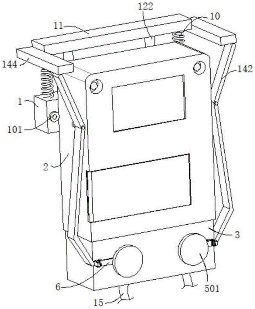
referring to fig. 1, fig. 2, fig. 3, fig. 4, fig. 5 and fig. 9, a high security is smart electric meter for theftproof, including setting firmly mounting panel 1 in ammeter case and can dismantle ammeter main part 2 of being connected with mounting panel 1, be provided with coupling assembling between ammeter main part 2 and the mounting panel 1, be provided with high definition digtal camera 101 on the mounting panel 1, the bottom side of ammeter main part 2 is provided with wiring shell 3, wiring hole 301 has been seted up on the wiring shell 3, swing joint has electric wire 15 in wiring hole 301, be provided with wiring mechanism in the wiring shell 3, wiring mechanism is including the wiring subassembly that is used for connecting electric wire 15 and the spacing subassembly of restriction wiring subassembly activity, and be provided with between coupling assembling and the spacing subassembly and stir the subassembly.
Specifically, when installing this smart electric meter at the ammeter case, install ammeter main part 2 on the mounting panel 1 of ammeter case through coupling assembling, the staff inserts electric wire 15 in wiring shell 3 through wiring hole 301, the wiring subassembly in the wiring shell 3 carries out the centre gripping to electric wire 15 and presses, when coupling assembling was installed to mounting panel 1 on ammeter main part 2 and the ammeter case afterwards, coupling assembling drove spacing subassembly work through stirring the subassembly, make spacing subassembly restrict the wiring subassembly, keep the wiring subassembly to the pressure of electric wire 15 and hold the connected state, thereby realize fast installing the fixed connection of ammeter main part 2 in the ammeter case and ammeter main part 2 and electric wire 15, improve staff's work efficiency, ammeter main part 2 is installed behind the ammeter case, high definition digtal camera 101 real-time work on the mounting panel 1, shoot the ammeter of opening the ammeter case, prevent that illegal personnel from stealing electricity or destroying the ammeter case, improve the security of equipment use.
Example 2:
referring to fig. 1, 6, 8 and 9, a high security smart electric meter for theft prevention is substantially the same as embodiment 1, and further, the wiring assembly includes a wiring holder 4 fixedly disposed in a wiring housing 3, a cushion block 401 is disposed in the wiring holder 4, the wiring assembly further includes a moving rod 5 slidably connected to the wiring housing 3, two ends of the moving rod 5 are respectively and fixedly provided with a pull block 501 and a press plate 502, the press plate 502 is movably abutted to the cushion block 401, the moving rod 5 is sleeved with a first elastic element 503, and two ends of the first elastic element 503 are respectively connected to the press plate 502 and an inner wall of the wiring housing 3.
Specifically, when electric wire 15 links to each other with ammeter main part 2, through pulling pull block 501, make pull block 501 drive clamp plate 502 through carriage release lever 5 and shift up, electric wire 15 inserts connection terminal 4 through wiring hole 301, the staff removes the pulling force to pull block 501 afterwards, make carriage release lever 5 automatic re-setting under first elastic element 503's elasticity effect, clamp plate 502 exerts pressure fixedly to electric wire 15 on 4 cushion 401 of connection terminal, through the structure of improve equipment, make it can carry out convenient clamping to electric wire 15, need not appurtenance such as screwdriver, make the staff in the operation, it is more swift.
Example 3:
referring to fig. 6 and 8, a high-security anti-theft smart meter is substantially the same as that in embodiment 2, and further, a plug 5021 is provided on the pressing plate 502, and a jack 4011 matched with the plug 5021 is provided on the spacer 401.
Specifically, the plug 5021 is provided under the pressure plate 502, so that the plug 5021 is inserted between the plurality of wires inside the wire 15, and the contact surface between the pressure plate 502 and the wire 15 is increased, thereby normally transmitting the current.
Example 4:
referring to fig. 1, fig. 2, fig. 4, and fig. 5, a smart electric meter for high security anti-theft is substantially the same as embodiment 3, further, the connection assembly includes an insert 9 fixedly disposed on a back side of the electric meter main body 2, a slot 102 matched with the insert 9 is disposed on the mounting plate 1, the connection assembly further includes a fourth elastic element 10 fixedly disposed on the mounting plate 1, one end of the fourth elastic element 10, which is far away from the mounting plate 1, is connected with a moving plate 11, a mounting rod 122 is disposed on the moving plate 11, and mounting holes 13 matched with the mounting rod 122 are disposed on both the mounting plate 1 and the insert 9.
Specifically, when the ammeter main body 2 is installed in the ammeter box, the insertion block 9 on the back side of the ammeter main body 2 is inserted into the insertion slot 102 of the mounting plate 1, so that the ammeter main body 2 and the ammeter box are preliminarily fixed, and then the mounting rod 122 on the movable plate 11 is inserted into the mounting holes 13 of the mounting plate 1 and the insertion block 9 under the elastic action of the fourth elastic element 10, so that the ammeter main body 2 and the mounting plate 1 in the ammeter box are stably connected.
Example 5:
referring to fig. 1, 2, 4 and 5, a high-security anti-theft smart meter is substantially the same as embodiment 4, further, a sliding groove 12 is formed on a moving plate 11, a sliding plate 121 is slidably connected in the sliding groove 12, and a mounting rod 122 is fixedly arranged on the sliding plate 121.
Specifically, the sliding plate 121 drives the mounting rod 122 to move relative to the moving plate 11, so that the mounting rod 122 is staggered with the mounting hole 13, the moving plate 11 cannot move downwards under the action of the fourth elastic element 10, at the moment, the electric wire 15 and the electric meter main body 2 can be connected, and the situation that the moving plate 11 moves downwards to drive the shifting assembly to work, so that the limiting assembly drives the wiring assembly, the wiring assembly is limited, the moving rod 5 cannot drive the pressing plate 502 to move, and the pressing plate 502 cannot apply pressure to fix the electric wire 15 is avoided; and when the staff promoted installation pole 122 to make installation pole 122 just right to the time with mounting hole 13, installation pole 122 got into in mounting hole 13 of inserted block 9 under the elasticity pulling of fourth elastic element 10, coupling assembling when this moment to ammeter main part 2 and ammeter case internally mounted, coupling assembling drives spacing subassembly work through stirring the subassembly, make spacing subassembly restrict the wiring subassembly, thereby realize installing ammeter main part 2 in the ammeter case and ammeter main part 2 and electric wire 15's fixed connection fast, staff's work efficiency is improved.
Example 6:
referring to fig. 1, 2, 3, 6, 7, 10 and 11, a high-safety anti-theft smart electric meter is substantially the same as that in embodiment 4, further, the limiting component includes a connecting rod 6 fixedly disposed on the moving rod 5, a first rack plate 601 is disposed on the connecting rod 6, a rack frame 7 is engaged and connected to the outer side of the first rack plate 601, the rack frame 7 is slidably connected to the wiring housing 3, a sliding block 801 is fixedly disposed at the bottom of the rack frame 7, a sliding groove 8 matched with the sliding block 801 is disposed on the wiring housing 3, and a third elastic element 802 is disposed between the sliding block 801 and the inner wall of the sliding groove 8.
Further, the toggle assembly comprises an ear plate 14 fixedly arranged on the electricity meter main body 2, a rotating shaft 141 is rotatably connected to the ear plate 14, a toggle rod 142 is fixedly arranged on the rotating shaft 141, a torsion spring 143 used for resetting and rotating the toggle rod 142 is further arranged between the rotating shaft 141 and the ear plate 14 in the circumferential direction, the bottom of the toggle rod 142 is movably abutted to the rack frame 7, the toggle assembly further comprises a support plate 144 fixedly arranged on the moving plate 11, and the support plate 144 is movably abutted to the top of the toggle rod 142.
Further, the tap lever 142 includes an intermediate lever 1421 and two pressing levers 1422 disposed at two ends of the intermediate lever 1421, the two pressing levers 1422 respectively movably abut against the support plate 144 and the rack 7, each pressing lever 1422 is disposed obliquely to the intermediate lever 1421, and an angle between the pressing lever 1422 and the intermediate lever 1421 is an obtuse angle.
Specifically, when the mounting rod 122 is aligned with the mounting hole 13, the mounting rod 122 moves downward with the moving plate 11 under the elastic force of the fourth elastic element 10, so that the mounting plate 1 is connected with the electric meter main body 2, the support plate 144 on the side edge pushes against the pressing rod 1422 on the upper side of the moving rod 142 when the moving plate 11 moves downward, so that the moving rod 142 rotates around the rotating shaft 141, the pressing rod 1422 on the lower side of the moving rod 142 pushes the rack 7, so that the rack 7 is engaged with the first rack plate 601, the first rack plate 601 limits the position of the moving rod 5 at the moment, the pressing plate 502 keeps a fixed pressing state on the electric wire 15 at the moment, and unstable power supply caused by looseness in the clamping and using process of the pressing plate 502 is avoided.
Example 7:
referring to fig. 6 and 7, a smart meter for high security and theft prevention is basically the same as that of embodiment 6, and further, the rack 7 includes a U-shaped outer frame 701 slidably connected to the terminal housing 3, second elastic elements 702 are provided on both inner walls of the U-shaped outer frame 701, a second rack plate 703 engaged with the first rack plate 601 is provided between the two second elastic elements 702, and the second rack plate 703 is slidably connected in the U-shaped outer frame 701.
Specifically, when the electric wire 15 is inserted at different angles or is clamped with electric wires 15 of different sizes, the thickness of the electric wire 15 clamped by the pressing plate 502 is different, the clamping distance between the pressing plate 502 and the cushion block 401 is different, the movable rod 5 is not at the same height when clamping and fixing the electric wire 15 every time, the first rack plate 601 is not necessarily meshed with the second rack plate 703, the condition that the tooth end surfaces are connected may occur, the second rack plate 703 is elastically arranged in the U-shaped outer frame 701, the second rack plate 703 can slightly float up and down, the second rack plate 703 is completely meshed with the first rack plate 601, the clamping connection state of the pressing plate 502 to the electric wire 15 is maintained, and the practicability of the electric wire 15 is improved.
Example 8:
referring to fig. 1 and 4, a high-security smart meter for theft prevention is substantially the same as that of embodiment 6, and further, an alarm 103 and a push switch 104 electrically connected to the alarm 103 are disposed on the mounting plate 1, and the push switch 104 is movably abutted against the bottom of the moving plate 11.
Specifically, when the ammeter needs to be disassembled or the electric wire 15 needs to be disassembled, the operator lifts the moving plate 11, the moving plate 11 moves upwards, the moving plate 11 no longer abuts against the press switch 104, the press switch 104 elastically resets and drives the alarm 103 to give an alarm, other people are reminded that the ammeter is in a disassembling state, and illegal disassembling and assembling of the ammeter or illegal electricity stealing behaviors are warned conveniently.
The above description is only for the preferred embodiment of the present invention, but the scope of the present invention is not limited thereto, and any person skilled in the art should be considered to be within the technical scope of the present invention, and the technical solutions and the inventive concepts thereof according to the present invention should be equivalent or changed within the scope of the present invention.