This application is a divisional application of the chinese patent application entitled "tether fastener, body panel and tether assembly, vehicle" filed on 2016, 5, 4, 2016 and having the application number 201610289201.7.
Detailed Description
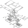
Fig. 1 is an exploded view of a vehicle body panel and tether assembly 10 including fastener clips 20 (fig. 1-6), 760 (fig. 7-8), tether straps 30, 730, and a tether clip bracket 40. The cleat bracket 40 may be attached to a body piece 60, such as a tower or pillar portion of the body piece 60. The body piece 60 may be a portion of a plastic trim piece, a body panel, or any other suitable type of panel. According to another embodiment, the body panel 70 includes both the cleat bracket 40 and the body piece 60. For example, once the tether clip bracket 40 and the body piece 60 are attached via welds, rivet screws, doghouse (dog house) or other suitable fasteners, the body panel 70 is attached and detached from the fastener clip 20. Cleat bracket 40 may be made of plastic, carbon fiber, fiberglass, steel, aluminum, magnesium, leather, rubber, wood, or any other suitable type of material. According to one embodiment, the body piece 60 may be a plastic trim cover for a B-pillar in a vehicle chassis, and may be made of polyvinyl chloride or any other suitable type of plastic known in the art. The body piece 60, fastener tether clips 20, 700, and tether belts 30, 730 may be coupled or otherwise suitably attached to another engagement structure 50, such as a vehicle chassis, structural frame, body panel, wall, substrate, or any other suitable object. The tether securing device 10 is attached to a body panel 70 and to a slot 52 in the vehicle chassis 50.
The tether belts 30, 222, 224, 730 are multi-twisted reinforced and thus absorb deployment energy and decelerate the body panel 70 in a controlled manner to avoid breakage of the belts. For example, the tether belts 30, 222, 224, 730 include multiple strands of material, such as a mesh reinforcement on an elastic material, to strengthen the tether belts 30, 222, 224, 730 such that the tether belts 30, 222, 224, 730 resist breakage and do not allow the body panel to travel more than a predetermined distance. The tether belts 30, 730 and components of the tether clip 20 may also be made of polyvinyl chloride or any suitable plastic, although any other suitable material may be used, such as carbon fiber, wire, or cable. The multi-stranded material may be a nylon mesh, rope mesh, metal mesh, rubber, plastic, polyester, aluminum, steel, mesh or braid, bungee cord, or any suitable stranded material. Multi-stranded materials such as ropes or steel cables are capable of withstanding high tensile forces and exhibit very high failure yield points and thus are effective in preventing failure of the tether belts 30, 222, 224, 730. For example, if one or some of the strands of the net or cable stretches or even breaks, strain is evident, while the remaining strands continue to prevent breakage and ensure the safety of the tethering straps 30, 222, 224, 730.
It should be understood that the implementation of other variations and modifications of the body panel and tether fastener assembly 10 (including 700), as well as the various aspects thereof illustrated in the drawings and described herein, will be apparent to those skilled in the art, and that the present invention is not limited by these specific embodiments described. For example, the fastener tether clip 20 and tether strap 30, 222, 224, 730 may be coupled to the tether clip bracket 40 in any suitable manner. For example, the tether strap 30, 222, 224, 730 may be coupled to the cleat bracket 40 on one side of the cleat bracket 40 or on any portion of the cleat bracket 40, or to the body piece 60 such as on an interior trim surface or on any portion of a tower or column.
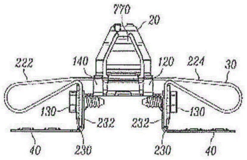
Figure 2 illustrates a perspective view of a vehicle body panel and tether fastener assembly 10 when attached, according to one embodiment of the present invention. According to one embodiment, as shown in fig. 1-6, the fastener tether clip 20, 700 is coupled to the tether strap 30, 222, 224, 730 such that the tether strap 30, 222, 224, 730 bends to allow the fastener clip 20 to enter into the tether clip bracket 40 of the vehicle body panel 70. The cleat bracket 40 may be attached to the body piece 60, for example, via a fastening mechanism 530 such as a rivet, ultrasonic or thermal weld, screw, pin, or other suitable fastening mechanism 130, and may be preassembled. According to one embodiment, the tether strap 30, 222, 224, 730 is attached to the tether clip bracket 40 via at least two arms 222, 224, for example, to the tether clip bracket 40 by a fastening mechanism 130 such as a screw shown in fig. 1 and 4 and a single arm shown in fig. 6, 7 or 8. Alternatively, three or more flexible arms 222, 224 are contemplated. Alternatively, the tether strap 30 is attached to the tether clip bracket 40 via a ribbon cable, strap, flexible tether, weld, or other flat cable. For example, the tether strap 30, 222, 224, 730 may be coupled to the tether clip bracket 40 via the base 120 of the fastener clip 20, 700 along one, two, three, or all four sides of the base 120. As a result, the tether strap 30, 222, 224, 730 may have a suitable amount of material, including portions of varying thickness, such as an elastic material covered by a mesh or alternatively an externally applied object or device (such as a chain, cable, metal strap), sufficient to carry any desired amount of detachment force.
According to one embodiment, each of the arms 30, 222, 224, 730 may be attached to the base 120 via the channel 140 shown in fig. 1-5 or the strap attachment 710 shown in fig. 6, 7, and 8. For example, when the cleat bracket 40 is detached from the fastener clip 20 that is slid to the engagement structure 50 (such as a vehicle chassis), the detachment force may be absorbed by the resilient material within the straps 30, 222, 224, 730, such that the mesh, such as a nylon wrap, acts as a reinforcement to properly maintain the coupling between the fastener clip 20 coupled to the engagement structure 50 and the body panel 70. The straps 30, 222, 224, 730 may include bumpers, tears and weakenings, or any other suitable mechanism for absorbing all or a portion of the energy resulting from the detachment of the joint structure 50 from the body panel 70.
According to one embodiment, in response to a vehicle collision and the impact of a related event such as airbag deployment, the tether clip bracket 40 of the body panel 70 is detached from the fastener clip 20 on the engagement structure 50. Accordingly, the arms 30, 222, 224, 730 may include a sufficient amount of material, such as molded plastic, mesh reinforcement, nylon wrap, or other suitable material, to ensure that the first engagement structure or vehicle chassis 50 remains coupled with the body panel 60 via the tether belts 30, 70.
The tether strap 30 further includes a tether strap coupler 230, 710 at one or both ends of the tether strap 30, 730. The tether strap coupler 230, 710 is suitably coupled to a strap slot 232, 732 formed on the tether clip bracket 40, 730. According to the embodiment shown in fig. 4, tether strap coupler 230 and strap slot 232 are parallel. Optionally, the tether strap coupler 230, 710 and the strap slot 232, 732 are orthogonally positioned such that the tether strap coupler 230, 710 may be inserted into the strap slot 232, 732 and, when rotated, the tether strap coupler 230, 710 will resist removal from the strap slot 230, 732. Although the tether strap coupler 230 is shown as having the general profile of an end of a strap, the tether strap coupler 230, 710 may take the form or shape of any suitable attachment shape, such as a T-bar, ball, arrow, triangle, square, and/or hook (as described in this application) for complementary engagement within the strap slot 232, 732. The strap slots 232, 732 may be adapted to accept insertion of the tether strap coupler 230, 710 and resist detachment of the tether strap coupler 230, 710 from the engagement structure slot 52.
Figure 5 illustrates a top view of the vehicle body panel and tether fastener assembly 10 according to one embodiment of the present invention. According to this embodiment, the base 120 of the fastener clip 20 includes tether retention tabs 248, 550. According to this embodiment, the tether retention tabs 248, 550 retain the fastener clip 20 by virtue of the corners or bends of the tether retention tabs 248, 550. For example, when the fastener clip 20 engages the tether strap 30, the tether retention tabs 248, 550 spring inward while frictionally engaging the strap 30 until the fastener clip 20 is fully inserted into the strap 30 and clamps the strap 30. Once fully inserted, the tether retention tabs 248, 550 expand via spring action to engage the strap 30. For example, when the fastener clip 20 is clipped into the slot 52 such that the engagement structure 50 compresses the tether retention tabs 248, 550 into the strap 30 and thus tightly grips the strap 30, the strap 30 may engage the tether retention tabs 248, 550 via the notches 242. Further, the frictional engagement and spring tension between the tether retention tab 248 and the engagement structure 50 may be sufficient to allow for relatively easy insertion while increasing the relative force to extract the fastener clip 20 from the slot 52. In other words, because the engagement structure 50 is clamped between the notch 242 on the arm 770 and the tether retention tabs 248, 550, the notch 242 on the arm 770 springs toward the engagement structure 50 and pushes the engagement structure 50 into the tether retention tabs 248, 550 that tightly clamp the strap 30.
According to one embodiment shown in fig. 8, the tether strap 710 includes a clamp 750 to facilitate clamping, insertion, and rotation of the strap coupler 710, fastener 760, and tether cap 700 into the engagement structure slot 52. For example, the installer may more easily grasp the clip 750 with their fingers to insert (and optionally twist) the strap coupler 710 and fastener 760 into the tether cap 700 and into the engagement structure slot 52. Although clip 750 is shown in the shape of a thickened end of band coupler 710, clip 750 can be any suitable shape. Grip 750 may be an "X" (also known as an X stop) or may be formed in any shape suitable to allow manipulation of tape coupler 710 into engagement structure slot 52, such as an "I", "T", "V", "O", or any single or multi-sided object.
According to one embodiment, the body piece 60 including the cleat bracket 40 is attached to a tower or shell of the body panel, which may be part of the body piece 60. For example, the cleat bracket 40, the fastener clips 20, 700, 760, and the body piece 60 may be pre-assembled into an assembly suitable for the vehicle chassis 50. The entire assembly is secured via fastener clips 20, 700, 760 to a pillar such as an a-pillar, B-pillar or C-pillar, or any suitable pillar of the vehicle chassis 50 via the slot 52. The slot 52 may be sized to allow relatively easy insertion of the fastener clip 20, 700 while resisting separation between the fastener clip 20, 700 and the vehicle chassis 50. The slot 52 may have any shape, such as a rectangle, a circle, a square, a rectangle, a pentagon, a hexagon, a polygon, an n-sided polygon (where n is an integer), an ellipse, and/or an oval, or any suitable shape.
Fig. 6-8 and 8-13 depict one example of a strap 730, such as a metal, nylon, carbon fiber, rubber mesh reinforced, or plastic strap 730, with the strap 730 attached at one end in an open loop configuration. Other embodiments can have legs that include differently shaped arms/ legs 222, 224, 730, such as different radii of curvature or bends, spirals, angles, or any suitable shape to function as a shock absorber. The fastener clip 760 includes a pair of tangs (tan) 770 to engage the tether cap 700 in a tang slot in the tether cap 700. According to one embodiment, the catch 770 includes a notch or recess adapted to increase an extraction force for extracting the fastener clip 760 from the tether cap 700 relative to an insertion force. The catch 770 may be sized to engage the slot 52 of the vehicle chassis 50 to further increase the extraction force. According to one embodiment, a recess may be formed on the latch 770. For example, the notches or depressions may be formed by stamping one or more of the catches 770 (fig. 7 and 8 and 9-13) and the notches 242 (fig. 1, 3 and 4). The notch 242 may further include an edge that may include a abrupt angle, a single angle, multiple angles, a continuously changing angle, or an angle of any suitable size to allow the fastener clip 20, 760 and the tether cap 700 to be inserted into the slot 52 with relative ease, while increasing the extraction force. The notches 242 may be formed such that any angle may be used, including 0 °, 30 °, 45 °, 60 °, 89 °, 145 °, and so forth. The tether cap 700 may further include a tether cap arm 246, the tether cap arm 246 adapted to flex when inserted into the slot 52 and thereby expose a catch for engagement with the slot 52.
According to one embodiment, the tether cap 700 and the fastener clips 20, 920, 760 provide a detachment force of from at least 20 pounds to 50 pounds. So that the vehicle body panel 70 is properly detached from the vehicle chassis 50 by means of the tether belt 30 during an impact. Fastener clips 20, 720, 920 can be any suitable fastener clip, and can be any clip manufactured by Termax corporation of Crystal Lake, illinois. According to one embodiment, the fastener clips 20, 720 may be fastener clips such as part numbers 27000, 67000, 4405, 4570, 30611, 3842, 4210, and 71500, manufactured by Termax, inc. For example, any of the components of the body panel and tether fastener assembly 10 may be molded, extruded or formed in any suitable manner from plastic or any suitable material. Alternatively, any of the components of the body panel and tether fastener assembly 10 may be made from steel metal strips on a progressive die. The steps employed may include the formation of shear tabs and blanking to form holes and channels as is known in the art. Additionally, rubber, plastic, paint, or any suitable coating or covering may be applied to reduce buzz, squeak, and rattle (BSR) during operation of the vehicle.
Fig. 6-8 depict a tether securing apparatus 600 according to another embodiment. Examples have an open-circuit or non-endless feature as previously described. The tether securing apparatus 600 includes a tether fastener 770, a strap coupler 710 and a tether cap 700, a clamp 750, and an arm 246. Although shown with bands, bands 730 may have shapes, for example, with various curvatures, bends, spirals, or any suitable combination to further provide shock absorption. For example, if the airbag causes the body panel 70 to be detached from the chassis 50, the cap 700 remains with the chassis 50 while the fastener clips 760 remain with the body piece 60. The shock absorber formed in the belt 730 and the belt coupler 710 partially or substantially absorb energy resulting from the sudden disassembly of the body member 60. The hook fingers 540 may be operable to releasably connect to a chassis or body panel 60, such as a B-pillar body panel or other suitable object. For example, the hook fingers 540 and corresponding grooves 650 on the body build may be slid through the access openings onto corresponding couplers on the body panel 60. The hook finger 540 may have a tapered hook 670 to retain and also allow the hook finger 540 to be easily inserted into the vehicle body panel 60 while allowing for disassembly. For example, the hook fingers 540 may be removed from the body panel 60 by prying the hook fingers 540 and optional tapered hooks to disengage.
Fig. 7 depicts the tether fastener 600 in an engaged position (such that the coupler 710 is engaged in the cap 700) in accordance with another embodiment. An optional clip 760 may be inserted into the cap 700 to provide a desired releasable retention force for the clip 760 on the coupler 710. According to this embodiment, clip 760 is attached to cap 700 to releasably engage slot 52 of vehicle chassis 50. According to another embodiment, the clip 760 may have a base portion 544 that is flush with the coupler 710. Clip 760 further includes a catch 770 for engaging slot 52 of chassis 50. According to one embodiment, clip 760 includes two opposing catches 770 to hold the two sides of clip 720 together. The catch 770 may be a finger-like extension of the leg operable to bend to hold the catch 770 together.
Fig. 8 depicts a perspective view of a tether fastener 600 in a disengaged position, in accordance with another embodiment. When in the detachment mode, the tether cap 700 and the arm 246 operatively coupled to the vehicle chassis and the tether cap 700 are detached from the clip 760 while the coupler 710 remains coupled to the body panel 60.
The releasable connection in the tether fastener clip 20, 760, 700 comprises a series of attachments. A first releasable coupling is formed between optional clip 760 and cap 700. A second releasable coupling is formed between optional clip 760 and coupler 710. A third releasable coupling is formed between cap 700 and slot 52 formed in chassis 50. A fourth releasable coupling is formed between the hook fingers 540 (fig. 7 and 8) or the tether bracket 40 and the vehicle body panel 60 (fig. 1-6). For example, the insertion and extraction forces of each of the releasable couplings increase as the chassis 50 is approached.
According to one embodiment, the tether strap 30, 222, 224, 730 allows the vehicle chassis 50 to be separated from the body member 60 by a distance of approximately 100 mm. However, the displacement between the vehicle chassis 50 and the body member 60 may be any range of distances, including 50mm to 150mm, 25mm to 175mm, and 10mm to 500mm or any suitable distance. Further, the tether cap 700 detaches from the fastener clip 760 in response to a minimum detachment force of from 20 to 50 pounds, 10 to 100 pounds, and/or 5 to 200 pounds, or any suitable detachment force.
Fig. 9-18 depict a tether securing device 900 according to another embodiment. Another example has the open-circuit or non-endless belt 222, 730 feature as previously described.
Fastener clip 920 is coupled to vehicle chassis 50. Fastener clip 920 may optionally be further secured by screws 1540 into threaded barrels 1560 or any suitable fastener. The tether clip bracket 40 is detachably attached to the vehicle body panel 60. The fastener clip 920 further includes a tether hook 940 for attachment to the strap 222, 730.
Fastener clip 920 further includes a panel retainer 950, such as a tab formed at the end of tether hook 940, for insertion into retaining slot 960 to further secure and stabilize fastener 920 into chassis 50. After the clips 20, 920 are inserted into the slots 52, the clips 20, 920 remain in the slots 52 even during airbag actuation.
According to one embodiment, the tether clip bracket 40 is attached to the tether strap 222, 730 via the tether hook 970. When in the attached position (as is typically the case after vehicle assembly), the cleat bracket 40 may be in a non-orthogonal plane relative to the fastener clip 20. For example, if there is insufficient space for both the fastener clips 920 and the body panels 60, 70, the straps 22, 730 may simply be tethered a predetermined distance. In the event of airbag actuation, the tether clip bracket 40 quickly separates from the fastener clip 20 during disassembly. The looped tether straps 222, 730 control the acceleration, deceleration, and separation distance of the fastener clips 920 and the body panels 60, 70. When deployed, the cleat bracket 40 (with the body piece 70) and the fastener clip 920 (attached to the chassis 50) initially accelerate and then decelerate from each other to a safe predetermined distance.
As shown in fig. 9-10 and 15-17, the cleat bracket 40 may also be attached to a body piece 60, the body piece 60 including a tower or pillar portion of a body panel 70. The threaded tube 990 on the cleat bracket 40 may further be secured to the threaded hole 1610 on the body member 60 via screws 980. The body member 60 may be a plastic trim piece, a body panel such as a B-pillar body panel, or a portion of any other suitable type of panel.
As shown in fig. 11 and 13, according to one embodiment, the tether clip bracket 40 further includes an aperture 1110, the aperture 1110 being surrounded by two arms 1310 adjacent to the aperture 1110 to flex and absorb energy during deployment. According to another embodiment, the body panel 70 includes a pre-assembled combination of both the cleat bracket 40 and the body piece 60. For example, the clevis 930 on the cleat bracket 40 slides into the slot 530 of the body piece 60 and is attached via a weld, rivet screw, or other suitable fastener. As an assembly, the body panel 70 is tethered with a fastener clip 920. The fastener clip 920 and the cleat bracket 40 may be made of metal, plastic, carbon fiber, fiberglass, steel, aluminum, magnesium, leather, rubber, wood, or any other suitable type of material. According to one embodiment, the body member 60 may be a plastic trim cover for an A-pillar, B-pillar, and C-pillar in a vehicle chassis, and may be made of polyvinyl chloride or any other suitable type of material known in the art. Via the fastening device 10 (including the fastener tether clips 920, 700 and the tether straps 30, 730, 222, 224), the body piece 60 may be coupled or otherwise suitably attached to another interface structure 50, such as a vehicle chassis, a structural frame, a body panel, a wall, a base plate, or any other suitable object.
According to one embodiment, the fastener tether hook 940 and the bracket tether hook 970 are compressed or spring-clamped for attachment to the strap 30, 730, 222. The ends of the straps 30, 730, 222 may be tied and coupled, for example, by a fastening mechanism 130 such as a clamp. The fastening mechanism 130 may be or may further include a clamp, such as a wire 1200, staple, crimp sleeve, "hog hoop", or any suitable coupling mechanism. Optionally, the fastening mechanism 130 is a cover or shroud (such as tape) that covers the clip or wire 1200. Alternatively, three, four, five, six, or more suitable numbers of flexible arms 222, 224 for each tether strap are contemplated.
The tether belts 30, 730, 222, 224 are multi-strand reinforcing belts and thus absorb the deployment energy and decelerate the body panel 70 relative to the chassis 50 in a controlled manner to avoid breakage of the belts. For example, the tether belts 30, 730, 222, 224 include a multi-stranded material, such as a mesh reinforcement material over an elastic material. The mesh reinforcement material (mesh) reinforces the tether belts 30, 730, 222, 224 such that the elastic material on the tether belts 30, 730, 222, 224 elongates in a controlled manner while the mesh resists breakage and does not allow the body panel 70 to travel more than a predetermined distance from the chassis 50.
The entrainment coupler 210, fastening mechanism 130, and bracket strap coupler 710, as well as associated components, may be made of polyvinyl chloride or any suitable plastic, but any other suitable material may be used, such as carbon fiber, wire, or cable. The multi-stranded material may be a nylon mesh, rope mesh, metal mesh, rubber, plastic, polyester, aluminum, steel, mesh or braid, bungee cord, or any suitable stranded material. Multi-stranded materials such as ropes or steel cables are capable of withstanding high tensile forces and exhibit a high level of failure yield point, and thus are effective in preventing or significantly reducing failure of the tether belts 30, 730, 222, 224. For example, if one or several of the strands of the net or cable stretch or even break, the strain is evident, while the remaining strands remain intact and continue to prevent breakage and secure the tethering straps 30, 70, 222, 224. For example, the apparent strain of the strand or mesh may be used to determine the reuse, reassembly and reinstallation of the strap 30, 730 and any components of the tether securing apparatus 10, 1300.
It should be understood that the implementation of other variations and modifications of the body panel and tether fastener assembly 10, 600, 900, as well as the various aspects thereof illustrated in the drawings and described herein, will be apparent to those skilled in the art, and that the present invention is not limited by these specific embodiments described.
The cleat bracket 40 may further include a barb 1120 on the interior of the clevis 930, which barb 1120 snaps or pokes into the tower 70 and inhibits the clevis 930 from being removed or slid out of the slot 530 of the tower 70.
Alternatively, the tether strap 30, 222, 730 may be a ribbon cable, a strap, a flexible tether, a weld, or a suitable flat cable. As a result, the tether strap 30, 222, 730 may have any suitable amount of material sufficient to carry any desired amount of detachment force, including portions of varying thickness, such as an elastic material covered by a mesh or alternatively an externally applied object or device (such as a chain, cable, metal strap).
The straps 30, 222, 730 may include bumpers, tears and weakenings, or any other suitable mechanism for absorbing all or a portion of the energy resulting from the detachment of the joint structure 50 from the body panel 70.
In response to a vehicle collision and the impact of a related event, such as airbag deployment, the tether clip bracket 40 of the body panel 70 is detached from the fastener clip 920 on the interface structure 50. Accordingly, the arms 224, 222, 730 may include a sufficient amount of material, such as rubber, molded plastic, mesh reinforcement, nylon wrap, or other suitable material, to ensure that the first engagement structure or vehicle chassis 50 is separated from the body panel 60 by a predetermined distance and remains coupled via the tether strap 30, 730.
Wing 770 and wing recess 242 on opposite sides of fastener clips 920, 700 engage slot 52 of chassis 50.
As shown in fig. 9 and 10, the fastener clips 20, 920 have slots 1560 in their bases, the slots 1560 engaging fasteners 1540 such as pins or rivets.
The slot 52 can have any shape corresponding to the wings 770, 246, such as rectangular, circular, square, rectangular, pentagonal, hexagonal, polygonal, n-sided polygonal (where n is an integer), elliptical, and/or oval or any suitable shape.
The fastener clip 20, 920 includes a pair of catches 770 and fingers 780 to engage the slot 52 of the vehicle chassis 50. According to one embodiment, the catch 770 includes at least one notch or depression or bend adapted to increase the extraction force for extracting the fastener clip 20, 920 from the chassis slot 52 relative to the insertion force. The catch 770 may be sized to engage the slot 52 of the vehicle chassis 50 to further increase the extraction force. According to one embodiment, a recess may be formed in the catch 770 and/or finger 780. For example, the notches or depressions may be formed by stamping one or more of the catches and notches 242 (fig. 1, 3, and 4).
According to one embodiment, the fastening device 10 may be assembled via a vehicle assembly method comprising the following steps in any suitable order:
attaching the cleat bracket 40 to the vehicle body panel 70;
attaching the multi-strand reinforcing tape 222, 730 to the fastener clip 920;
a tether hook 970 coupling the multi-strand reinforcement strap 222, 730 to the tether clip bracket 930;
attaching fastener clip 920 to vehicle chassis 50; and
fastener clip 920 is coupled via insertion screw 1540.
Among other advantages, the tether strap forms a loop to couple the entrainment coupler and the support strap coupler. By forming the loop, other forms of attaching the tether strap to the fastener clip, such as by means of a screw, are not required. The tether securing device readily facilitates attachment of the vehicle chassis to the second interface structure while the integrated strap controls detachment of the vehicle chassis from the second interface structure. The tether strap absorbs the deployment energy and decelerates the body panel in a controlled manner to avoid breakage of the strap. According to one embodiment, the belt has a web reinforcement on the elastic material to strengthen the belt such that the belt resists breakage and does not allow the body panel to travel more than a predetermined distance. Since the cleat includes an integral strap, the body panel assembly may be preassembled with the strap and the cleat already attached to or ready for attachment to the vehicle chassis in a single step. As a result, a separate step of attaching the tether strap to the vehicle is not required. Because the tether strap is integrated into the tether clip and shipped to, for example, an automotive manufacturer for final assembly, the automotive manufacturer may omit the step of attaching the strap to the vehicle chassis because the tether strap is already integrated into the tether clip. Therefore, assembly costs are reduced, thereby reducing the production costs of the manufacturer. Further, the tether securing device reduces the likelihood of a false attachment of the tether strap between the vehicle chassis and the second engagement structure because the tether strap has been integrated with the tether clip at one end and has been attached to the second engagement structure, such as a vehicle body panel. In other words, the problem of inadvertently failing to attach a separate tether strap between the vehicle chassis and the body panel is greatly reduced or even eliminated. The tether strap facilitates controlled disengagement of the body panel and the vehicle chassis to allow deployment of the airbag, allowing the airbag to travel along a guide path that would otherwise be obstructed by the second engagement structure. Thus, the use of tether fastening devices reduces production costs and increases productivity and efficiency, while further improving reliability and safety. Those skilled in the art will readily recognize the use of the tether securing device in other applications such as aircraft, spacecraft, watercraft, furniture, and housing construction.
It should be understood that the implementation of other variations and modifications of the invention in its various aspects will be apparent to those of ordinary skill in the art, and that the invention is not limited by the specific embodiments described. It is therefore contemplated to cover by the present invention, any and all modifications, variations or equivalents that fall within the spirit and scope of the basic underlying principles disclosed and claimed herein.