CN1151503C - Cassette-tape video recorder with preamplifier fitted at master board - Google Patents
Cassette-tape video recorder with preamplifier fitted at master board Download PDFInfo
- Publication number
- CN1151503C CN1151503C CNB971025762A CN97102576A CN1151503C CN 1151503 C CN1151503 C CN 1151503C CN B971025762 A CNB971025762 A CN B971025762A CN 97102576 A CN97102576 A CN 97102576A CN 1151503 C CN1151503 C CN 1151503C
- Authority
- CN
- China
- Prior art keywords
- preamplifier
- deck
- main board
- video
- tape
- Prior art date
- Legal status (The legal status is an assumption and is not a legal conclusion. Google has not performed a legal analysis and makes no representation as to the accuracy of the status listed.)
- Expired - Lifetime
Links
Images

Classifications
-
- G—PHYSICS
- G11—INFORMATION STORAGE
- G11B—INFORMATION STORAGE BASED ON RELATIVE MOVEMENT BETWEEN RECORD CARRIER AND TRANSDUCER
- G11B33/00—Constructional parts, details or accessories not provided for in the other groups of this subclass
- G11B33/02—Cabinets; Cases; Stands; Disposition of apparatus therein or thereon
-
- G—PHYSICS
- G11—INFORMATION STORAGE
- G11B—INFORMATION STORAGE BASED ON RELATIVE MOVEMENT BETWEEN RECORD CARRIER AND TRANSDUCER
- G11B33/00—Constructional parts, details or accessories not provided for in the other groups of this subclass
- G11B33/12—Disposition of constructional parts in the apparatus, e.g. of power supply, of modules
- G11B33/121—Disposition of constructional parts in the apparatus, e.g. of power supply, of modules the apparatus comprising a single recording/reproducing device
-
- G—PHYSICS
- G11—INFORMATION STORAGE
- G11B—INFORMATION STORAGE BASED ON RELATIVE MOVEMENT BETWEEN RECORD CARRIER AND TRANSDUCER
- G11B25/00—Apparatus characterised by the shape of record carrier employed but not specific to the method of recording or reproducing, e.g. dictating apparatus; Combinations of such apparatus
- G11B25/06—Apparatus characterised by the shape of record carrier employed but not specific to the method of recording or reproducing, e.g. dictating apparatus; Combinations of such apparatus using web-form record carriers, e.g. tape
- G11B25/063—Apparatus characterised by the shape of record carrier employed but not specific to the method of recording or reproducing, e.g. dictating apparatus; Combinations of such apparatus using web-form record carriers, e.g. tape using tape inside container
-
- G—PHYSICS
- G11—INFORMATION STORAGE
- G11B—INFORMATION STORAGE BASED ON RELATIVE MOVEMENT BETWEEN RECORD CARRIER AND TRANSDUCER
- G11B33/00—Constructional parts, details or accessories not provided for in the other groups of this subclass
- G11B33/14—Reducing influence of physical parameters, e.g. temperature change, moisture, dust
- G11B33/1493—Electro-Magnetic Interference [EMI] or Radio Frequency Interference [RFI] shielding; grounding of static charges
-
- H—ELECTRICITY
- H05—ELECTRIC TECHNIQUES NOT OTHERWISE PROVIDED FOR
- H05K—PRINTED CIRCUITS; CASINGS OR CONSTRUCTIONAL DETAILS OF ELECTRIC APPARATUS; MANUFACTURE OF ASSEMBLAGES OF ELECTRICAL COMPONENTS
- H05K9/00—Screening of apparatus or components against electric or magnetic fields
- H05K9/0007—Casings
- H05K9/002—Casings with localised screening
- H05K9/0039—Galvanic coupling of ground layer on printed circuit board [PCB] to conductive casing
Landscapes
- Engineering & Computer Science (AREA)
- Microelectronics & Electronic Packaging (AREA)
- Shielding Devices Or Components To Electric Or Magnetic Fields (AREA)
- Television Signal Processing For Recording (AREA)
Abstract
本发明所提出的前置放大器安装在主板上的盒式磁带录像机包括:一个检取视频信号的走带机构,一根将走带机构所检取的视频信号加到前置放大器的连接电缆,一块上面装有前置放大器的主板,以及一个与走带机构的一部分接触用来屏前置放大器的屏蔽盒。由于前置放大器安装在主板上省去了组装前置放大器组装工艺,因此提高了生产率,而屏蔽前置放大器的屏蔽盒与走带机构齐平安装增大了屏蔽盒和走带机构的接触面积,从而减小了噪声干扰。
The video cassette recorder in which the preamplifier proposed by the present invention is installed on the mainboard comprises: a tape transport mechanism for picking up video signals, a connecting cable that adds the video signal picked up by the tape deck mechanism to the preamplifier, A main board with the preamp on it, and a shield that contacts part of the deck to shield the preamp. Productivity is improved because the preamplifier is mounted on the main board eliminating the need to assemble the preamplifier assembly process, while the shield box for the shielded preamp is mounted flush with the deck to increase the contact area between the shield box and the deck , thereby reducing noise interference.
Description
技术领域technical field
本发明与盒式磁带录像机(VCR)板有关,具体地说,与前置放大器安装在主板上的VCR有关。The present invention relates to video cassette recorder (VCR) boards, and more particularly, to VCRs with preamplifiers mounted on the motherboard.
背景技术Background technique
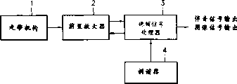
图1示出了通常的VCR的方框图。Fig. 1 shows a block diagram of a conventional VCR.
如图1所示,在走带机构1检取录在录像带(未示出)上的视频信号输出时,前置放大器2将所检取的微弱视频信号加以放大后输出给视频信号处理器3。此外,在录取TV广播信号时,调谐器4选取一个TV广播信号。所选的TV广播信号由视频信号处理器3处理、由前置放大器2放大后,再由走带机构1录制录像带上。视频信号处理器3对从磁带上恢复出来的视频信号进行处理,将此视频信号分解成图像信号和伴音信号输出。在通常的VCR中,前置放大器板是与主板分开的,如图2所示,情况如下面所述。As shown in Figure 1, when the
图2是一个透视图,示出了普通VCR的前置放大器板与主板分开的情况。Fig. 2 is a perspective view showing a situation where the preamplifier board of a general VCR is separated from the main board.
在图2中,通过走带机构21中的磁鼓22从录像带上检取的视频信号通过电缆23输出给前置放大器板25。In FIG. 2 , video signals picked up from a video tape by a
为了防止所检取的微弱视频信号受到外界噪声的干扰,前置放大器板25是密封在一个屏蔽盒24内的。由磁鼓22检取的视频信号,通过连接电缆23从磁鼓22送到前置放大器板25,在那里放大60dB左右。在前置放大器板25中得到放大的视频信号再送至主板26上的视频信号处理器3处理。由于前置放大器板25是象图2所示那样与主板26垂直连接的,因此在磁鼓22和前置放大器板25之间连接电缆23的生产率很低,这是因为这样安装的前置放大器板25使VCR的内部空间更加狭窄而造成的。此外,由于前置放大器板25与主板26垂直连接,走带机构21与屏蔽盒24之间的接触面积较小,很难保证可靠的接地,从而也就不能满意地消除外界噪声的干扰。In order to prevent the picked-up weak video signal from being disturbed by external noise, the
发明内容Contents of the invention
本发明的目的是提供一种VCR,这种VCR由于前置放大器安装在主板上而使VCR的生产率得到提高,由于屏蔽盒的接地表面较大而充分地消除了噪声的干扰。SUMMARY OF THE INVENTION An object of the present invention is to provide a VCR in which the productivity of the VCR is improved due to the mounting of the preamplifier on the main board, and interference of noise is sufficiently eliminated due to the large ground surface of the shield case.
为了达到以上目的,本发明所提出的一种前置放大器安装在主板上的盒式磁带录像机,所述录像机包括:一个检取视频信号的走带机构;一根将所述走带机构所检取的视频信号加到前置放大器的连接电缆;一块上面装有所述前置放大器的主板;以及一个屏蔽盒,用来屏蔽所述前置放大器,并且由于与所述走带机构齐平,因此与所述走带机构有比较大的表面接触。In order to achieve the above object, a kind of preamplifier that the present invention proposes is installed on the videocassette video recorder on the main board, described video recorder comprises: a tape transport mechanism that retrieves the video signal; A connection cable from which the video signal taken is applied to the preamplifier; a motherboard on which the preamplifier is mounted; and a shielding box for shielding the preamplifier, and since it is flush with the deck, There is thus relatively large surface contact with the deck.
屏蔽盒由于与走带机构齐平,因此与走带机构接触的表面比较大。Since the shielding box is flush with the deck, it has a relatively large surface in contact with the deck.
附图说明Description of drawings
本发明的以上目的和优点通过以下结合附图对本发明的优选实施例的详细说明就会更加清楚。在这些附图中:The above objects and advantages of the present invention will be more clear through the following detailed description of the preferred embodiments of the present invention in conjunction with the accompanying drawings. In these drawings:
图1示出了普通VCR的方框图;Fig. 1 shows the block diagram of common VCR;
图2为示出普通VCR的前置放大器板与主板分开的情况的透视图;以及2 is a perspective view showing a situation where a preamplifier board of a general VCR is separated from a main board; and
图3为示出本发明的VCR的前置放大器安装在主板上的情况的透视图。3 is a perspective view showing a state where a preamplifier of a VCR of the present invention is mounted on a main board.
具体实施方式Detailed ways
下面将结合这些附图对本发明进行详细说明。The present invention will be described in detail below with reference to these drawings.
图3示出了本发明所提出的前置放大器安装在主板上的VCR的局部情况。Fig. 3 shows a partial situation of the VCR with the preamplifier proposed by the present invention installed on the motherboard.
由图3可见,这部分设备包括走带机构31、磁鼓32、连接电缆33、屏蔽盒34和主板35。As can be seen from FIG. 3 , this part of the equipment includes a tape transport mechanism 31 , a magnetic drum 32 , a connecting cable 33 , a shielding box 34 and a main board 35 .
在图3中,由走带机构31中的磁鼓32检取的再现信号通过连接电缆33加到安装在主板35上的前置放大器(未具体示出)。与走带机构31接触的屏蔽盒34将接到位于主板35上的前置放大器的连接电缆33和主板上安置前置放大器的部分封在盒内,以便将再现的微弱视频信号与外界噪声隔离。In FIG. 3, the reproduced signal picked up by the head drum 32 in the deck 31 is supplied to a preamplifier (not specifically shown) mounted on a main board 35 through a connection cable 33. In FIG. The shielding box 34 that is in contact with the tape transport mechanism 31 seals the connection cable 33 that is connected to the preamplifier on the mainboard 35 and the part of the preamplifier on the mainboard, so that the weak video signal reproduced is isolated from external noise .
这样,由于安装在主板35上的前置放大器几乎与走带机构31齐平,因此可以通过将屏蔽盒34直接大面积地与走带机构31接触得到良好的接地效果。In this way, since the preamplifier installed on the main board 35 is almost flush with the tape transport mechanism 31 , a good grounding effect can be obtained by directly contacting the shielding box 34 with the tape transport mechanism 31 in a large area.
在本发明所提出的这种前置放大器安装在主板上的VCR中,由于前置放大器安装在主板上,省去了将前置放大器板与主板组装的工艺过程,因此可以提高生产率。此外,由于屏蔽前置放大器的屏蔽盒安装成与走带机构部分齐平,增大了屏蔽盒与走带机构之间的接触面积,因此可以有效地减小外界噪声的干扰。In the VCR in which the preamplifier is installed on the mainboard proposed by the present invention, since the preamplifier is installed on the mainboard, the process of assembling the preamplifier board and the mainboard is omitted, so the productivity can be improved. In addition, since the shielding box of the shielding preamplifier is installed flush with the tape deck, the contact area between the shielding box and the tape deck is increased, thereby effectively reducing the interference of external noise.
Claims (1)
Applications Claiming Priority (3)
| Application Number | Priority Date | Filing Date | Title |
|---|---|---|---|
| KR10610/96 | 1996-04-09 | ||
| KR1019960010610A KR970071765A (en) | 1996-04-09 | 1996-04-09 | Integrated preamplifier into mainboard |
| KR10610/1996 | 1996-04-09 |
Publications (2)
| Publication Number | Publication Date |
|---|---|
| CN1162174A CN1162174A (en) | 1997-10-15 |
| CN1151503C true CN1151503C (en) | 2004-05-26 |
Family
ID=19455329
Family Applications (1)
| Application Number | Title | Priority Date | Filing Date |
|---|---|---|---|
| CNB971025762A Expired - Lifetime CN1151503C (en) | 1996-04-09 | 1997-02-27 | Cassette-tape video recorder with preamplifier fitted at master board |
Country Status (3)
| Country | Link |
|---|---|
| US (1) | US6483716B1 (en) |
| KR (1) | KR970071765A (en) |
| CN (1) | CN1151503C (en) |
Families Citing this family (1)
| Publication number | Priority date | Publication date | Assignee | Title |
|---|---|---|---|---|
| WO2006005221A1 (en) * | 2004-07-09 | 2006-01-19 | Sae Magnetics (H. K.) Ltd. | “2-step contact” clamping fixture for the flexible print circuit on a head gimbal assembly |
Family Cites Families (2)
| Publication number | Priority date | Publication date | Assignee | Title |
|---|---|---|---|---|
| US4578718A (en) * | 1983-06-16 | 1986-03-25 | Bell & Howell Company | Control arrangement and method for video tape recorder |
| US4972190A (en) * | 1989-06-12 | 1990-11-20 | Aerocorp Technologies Inc. | Analog signal digitizer for recording on a video |
-
1996
- 1996-04-09 KR KR1019960010610A patent/KR970071765A/en not_active Ceased
-
1997
- 1997-02-27 CN CNB971025762A patent/CN1151503C/en not_active Expired - Lifetime
- 1997-02-28 US US08/808,183 patent/US6483716B1/en not_active Expired - Lifetime
Also Published As
| Publication number | Publication date |
|---|---|
| KR970071765A (en) | 1997-11-07 |
| CN1162174A (en) | 1997-10-15 |
| US6483716B1 (en) | 2002-11-19 |
Similar Documents
| Publication | Publication Date | Title |
|---|---|---|
| CN1151503C (en) | Cassette-tape video recorder with preamplifier fitted at master board | |
| CN1622749A (en) | Electronic device and circuit module device | |
| JP2000269613A (en) | Unwanted radiation printed circuit board | |
| US5334798A (en) | Interconnect cable with built-in shielding and method of use | |
| JPH08148877A (en) | Electronic device shielding device | |
| JP2921538B2 (en) | Video device and video device | |
| JP3659402B2 (en) | Cabinet structure of magnetic recording device | |
| JP2571891Y2 (en) | Video tape recording and playback device | |
| JPH0846894A (en) | Video equipment | |
| EP1416493A2 (en) | Audio and video combined apparatus | |
| JP2748534B2 (en) | Magnetic recording / reproducing device | |
| JP3163894B2 (en) | Composite AV device | |
| CN1115070A (en) | Drum unit signal transmission method and thus drum unit | |
| JPH0441518Y2 (en) | ||
| JPH08306023A (en) | Signal reproducing device and portable video tape recorder | |
| KR19990017004U (en) | Grounding Device for Video Cassette Recorder | |
| JP2510149Y2 (en) | Magnetic playback device | |
| JPH0421988A (en) | Radio wave fault preventing structure for magnetic disk device | |
| DUDIK | Playback amplifier with high interference immunity[Abstract Only] | |
| JP2504908Y2 (en) | Flexible wiring board | |
| JPS62171288A (en) | Recording picture quality compensation circuit for video tape recorder | |
| KR200153818Y1 (en) | Deck Grounding Structure of VCR | |
| KR970003696Y1 (en) | Head drum earth device of tape recorder | |
| JP3192004B2 (en) | Noise reduction circuit of floppy disk drive | |
| KR19990015000U (en) | Grounding structure of video cassette recorder |
Legal Events
| Date | Code | Title | Description |
|---|---|---|---|
| C10 | Entry into substantive examination | ||
| SE01 | Entry into force of request for substantive examination | ||
| C06 | Publication | ||
| PB01 | Publication | ||
| C14 | Grant of patent or utility model | ||
| GR01 | Patent grant | ||
| CX01 | Expiry of patent term |
Granted publication date: 20040526 |
|
| CX01 | Expiry of patent term |