CN115093058A - Broiler chicken is slaughtered with discharging sewage purification unit - Google Patents
Broiler chicken is slaughtered with discharging sewage purification unit Download PDFInfo
- Publication number
- CN115093058A CN115093058A CN202210877013.1A CN202210877013A CN115093058A CN 115093058 A CN115093058 A CN 115093058A CN 202210877013 A CN202210877013 A CN 202210877013A CN 115093058 A CN115093058 A CN 115093058A
- Authority
- CN
- China
- Prior art keywords
- pipe
- bin
- pipes
- rotating
- wall
- Prior art date
- Legal status (The legal status is an assumption and is not a legal conclusion. Google has not performed a legal analysis and makes no representation as to the accuracy of the status listed.)
- Granted
Links
Images




Classifications
-
- C—CHEMISTRY; METALLURGY
- C02—TREATMENT OF WATER, WASTE WATER, SEWAGE, OR SLUDGE
- C02F—TREATMENT OF WATER, WASTE WATER, SEWAGE, OR SLUDGE
- C02F1/00—Treatment of water, waste water, or sewage
- C02F1/24—Treatment of water, waste water, or sewage by flotation
-
- C—CHEMISTRY; METALLURGY
- C02—TREATMENT OF WATER, WASTE WATER, SEWAGE, OR SLUDGE
- C02F—TREATMENT OF WATER, WASTE WATER, SEWAGE, OR SLUDGE
- C02F1/00—Treatment of water, waste water, or sewage
- C02F1/52—Treatment of water, waste water, or sewage by flocculation or precipitation of suspended impurities
- C02F1/5281—Installations for water purification using chemical agents
-
- C—CHEMISTRY; METALLURGY
- C02—TREATMENT OF WATER, WASTE WATER, SEWAGE, OR SLUDGE
- C02F—TREATMENT OF WATER, WASTE WATER, SEWAGE, OR SLUDGE
- C02F2103/00—Nature of the water, waste water, sewage or sludge to be treated
- C02F2103/22—Nature of the water, waste water, sewage or sludge to be treated from the processing of animals, e.g. poultry, fish, or parts thereof
Landscapes
- Chemical & Material Sciences (AREA)
- Life Sciences & Earth Sciences (AREA)
- Hydrology & Water Resources (AREA)
- Engineering & Computer Science (AREA)
- Environmental & Geological Engineering (AREA)
- Water Supply & Treatment (AREA)
- Organic Chemistry (AREA)
- Chemical Kinetics & Catalysis (AREA)
- General Chemical & Material Sciences (AREA)
- Physical Water Treatments (AREA)
- Separation Of Suspended Particles By Flocculating Agents (AREA)
Abstract
The invention relates to the technical field of sewage treatment, in particular to a purification treatment device for discharged sewage for slaughtering meat chickens, which comprises a treatment box, wherein a partition plate is rotatably arranged in the middle of the treatment box, the inside of the treatment box is divided into an upper side air flotation cavity and a lower side mixing cavity by the partition plate, and an air flotation structure is arranged in the air flotation cavity; a plurality of bulk material pipes are vertically arranged in the mixing cavity, are distributed in an annular shape, a plurality of bulk material holes are formed in the outer walls of the bulk material pipes, a drainage bin is arranged among the bulk material pipes, the outer wall of the drainage bin is conical, and a plurality of water holes are formed in the conical surface; the sewage is subjected to flocculation and air flotation treatment in an integrated mode, so that the number of equipment used for sewage treatment can be effectively reduced, the cost input is saved, the treatment mode is simplified, the time required by sewage treatment is shortened, and the working efficiency is improved.
Description
Technical Field
The invention relates to the technical field of sewage treatment, in particular to a device for purifying and treating discharged sewage for slaughtering broiler chickens.
Background
As is well known, slaughter houses are slaughtered meat chickens, a large amount of sewage is easily produced, the sewage is different from domestic sewage and industrial sewage, the domestic sewage and the industrial sewage contain a large amount of blood, hair, residual meat, floating oil and other impurities, the sewage concentration is high, the suspended matter impurities are more, and the sewage needs to be purified to avoid harm to the environment and human bodies caused by direct discharge of the sewage.
Traditional purification mode is earlier with the leading-in flocculation case of sewage, through adding the impurity flocculation and the settlement of stewing of flocculating agent messenger sewage, later again to carrying out air supporting edulcoration to the sewage through settlement treatment to float impurity in getting rid of the sewage and reach the purpose of purifying sewage, however this kind of purification mode is comparatively loaded down with trivial details, and used equipment is more, and the cost drops into great, and the required time of simultaneous processing is longer, and work efficiency is lower.
Disclosure of Invention
In order to solve the technical problem, the invention provides a device for purifying and treating discharged sewage for slaughtering broiler chickens.
In order to achieve the purpose, the invention adopts the technical scheme that:
the device for purifying and treating the discharged sewage for slaughtering the broiler chickens comprises a treatment box, wherein a partition plate is rotatably arranged in the middle of the treatment box and divides the inside of the treatment box into an upper side air flotation cavity and a lower side mixing cavity, and an air flotation structure is arranged in the air flotation cavity;
a plurality of bulk material pipes are vertically arranged in the mixing cavity, are distributed in an annular shape, a plurality of bulk material holes are formed in the outer wall of each bulk material pipe, a drainage bin is arranged among the bulk material pipes, the outer wall of the drainage bin is conical, and a plurality of water holes are formed in the conical surface;
baffle top slope is provided with a plurality of water pipes, water pipe and the sliding contact of handling incasement wall, water pipe bottom and compounding chamber intercommunication, have seted up the opening on the slope lateral wall of water pipe, baffle middle part intercommunication is provided with the overflow pipe to the baffle rotates with the overflow pipe to be connected, and the outer end of overflow pipe extends the outside of handling the case.
Furthermore, a rotating bin is rotatably mounted at the bottom of the mixing cavity, a plurality of square sliding cylinders are communicated and mounted on the outer wall of the circumference of the rotating bin, the vertical direction of the square sliding cylinders is even, sliding pipes are slidably arranged in the square sliding cylinders, one ends of the sliding pipes extend into the rotating bin, and the other ends of the sliding pipes extend into the treatment box;
the middle part of the rotating bin is provided with a poking plate and a hollow shaft, the hollow shaft penetrates through the poking plate and is fixedly connected with the poking plate, the outer wall of the poking plate is provided with a plurality of rollers in a contact manner, the rollers are provided with mounting plates, and the rollers are rotatably mounted at the end parts of the sliding pipes through the mounting plates;
the two ends of the pull rod are respectively and rotatably connected with the two adjacent rollers, and the pull rods form a polygon;
the bottom of the bulk material pipe is arranged on the sliding pipe.
Further, the sliding pipe is communicated with the bulk cargo pipe, and the sliding pipe is rotatably connected with the bulk cargo pipe;
the top of the hollow shaft is communicated with a material guide bin, the hollow shaft is rotatably connected with the material guide bin, the outer wall of the material guide bin is communicated with a plurality of material guide pipes, the outer ends of the material guide pipes are slidably inserted into the sliding pipes, and the material guide pipes are communicated with the sliding pipes;
an oval toothed ring is arranged among the plurality of bulk material pipes, a plurality of first gears are arranged on the outer wall of the oval toothed ring in a meshed mode, the first gears are mounted on the bulk material pipes, a rotating shaft is arranged in the middle of the oval toothed ring, a plurality of connecting rods are mounted on the outer wall of the rotating shaft, the outer ends of the connecting rods are fixed to the inner side wall of the oval toothed ring, the bottom of the rotating shaft penetrates through a rotating bin and a material guiding bin and extends into the material guiding bin, the rotating bin and the material guiding bin are rotatably connected with the rotating shaft, a plurality of fixing rods are mounted on the inner wall of the hollow shaft, and the tops of the fixing rods are connected with the bottom of the rotating shaft;
the top and the drainage storehouse bottom of pivot are connected, drainage storehouse top intercommunication is provided with the inlet tube to the inlet tube rotates with the drainage storehouse to be connected, and the outer end of inlet tube extends the outside of handling the case.
Furthermore, a rotating sleeve is rotatably mounted at the bottom of the treatment box, the top of the rotating sleeve penetrates through the treatment box and is connected with the bottom of the rotating bin, the bottom of the hollow shaft penetrates through the rotating sleeve and extends out of the treatment box, the hollow shaft is rotatably connected with the rotating sleeve, second gears are mounted on the hollow shaft and the rotating sleeve, third gears are arranged on the second gears in a meshed manner, the two third gears are mutually meshed and connected, the third gear on one second gear is separated from the other second gear, and the two third gears are rotatably mounted at the bottom of the treatment box;
the right-angle stand is installed to processing bottom of the case portion, installs the motor on the right-angle stand, and the output and a third gear drive of motor are connected.
Further, handle the bottom of the case portion and be provided with the dustcoat, the dustcoat is located the outside of rotating sleeve pipe, second gear, third gear, right-angle frame and motor, and hollow shaft bottom intercommunication is provided with the inlet pipe, and the dustcoat is passed to the outer end of inlet pipe, and the hollow shaft rotates with the inlet pipe to be connected.
Further, the air supporting structure includes that the spiral air diffusing pipe of fixed mounting at the baffle top and the annular air duct of rotation installation in the baffle bottom, and a plurality of gas pockets have been seted up to the progress of spiral air diffusing pipe, and a plurality of openings have been seted up at annular air duct top, and the opening passes the baffle and communicates with spiral air diffusing pipe, and the intercommunication is provided with the intake pipe on the annular air duct, and the outer end of intake pipe extends to the outside of handling the case.
Furthermore, the middle part of the partition board is in a bucket shape, a prismatic stop block is arranged above the bucket-shaped position of the partition board, the bottom of the prismatic stop block is provided with an upright rod, and the bottom of the upright rod is fixed on the partition board;
the overflow pipe communicates with the bottom of baffle hopper-shaped position to the baffle rotates with the overflow pipe to be connected.
Further, the top of the treatment box is conical, the conical top is communicated with a gathering cylinder, and the outer wall of the gathering cylinder is obliquely communicated with a sewage discharge hopper.
Compared with the prior art, the invention has the beneficial effects that: the sewage is subjected to flocculation and air flotation treatment in an integrated mode, so that the number of equipment used for sewage treatment can be effectively reduced, the cost input is saved, the treatment mode is simplified, the time required by sewage treatment is shortened, and the working efficiency is improved.
Drawings
In order to more clearly illustrate the embodiments of the present invention or the technical solutions in the prior art, the drawings used in the description of the embodiments or the prior art will be briefly described below, it is obvious that the drawings in the following description are only some embodiments described in the present invention, and for those skilled in the art, other drawings can be obtained according to the drawings without creative efforts.
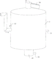
FIG. 1 is a front view of the present invention;
FIG. 2 is a schematic view of the internal structure of the housing of FIG. 1;
FIG. 3 is a schematic view of the internal structure of the treatment tank of FIG. 1;
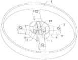
FIG. 4 is a schematic top view of the drainage chamber of FIG. 3;
FIG. 5 is a schematic view of the underside structure of the drainage silo of FIG. 4;
FIG. 6 is a schematic view showing the internal structure of the rotary bin of FIG. 5;
FIG. 7 is an enlarged view of the slide tube of FIG. 6;
FIG. 8 is an enlarged view of a portion A of FIG. 2;
in the drawings, the reference numbers: 1. a treatment box; 2. a partition plate; 3. a bulk pipe; 4. a drainage bin; 5. a water guide pipeline; 6. an overflow pipe; 7. rotating the bin; 8. a square sliding cylinder; 9. a slide pipe; 10. a poking plate; 11. a hollow shaft; 12. a roller; 13. mounting a plate; 14. a pull rod; 15. a material guiding bin; 16. a material guide pipe; 17. an elliptical ring gear; 18. a first gear; 19. a rotating shaft; 20. a connecting rod; 21. a fixing rod; 22. a water inlet pipe; 23. rotating the sleeve; 24. a second gear; 25. a third gear; 26. a right-angle frame; 27. a motor; 28. a housing; 29. a feed pipe; 30. a spiral air dispersing pipe; 31. an annular gas duct; 32. an air inlet pipe; 33. a prismatic stop block; 34. erecting a rod; 35. a collection cylinder; 36. a sewage discharge hopper.
Detailed Description
The technical solutions in the embodiments of the present invention will be clearly and completely described below with reference to the drawings in the embodiments of the present invention, and it is obvious that the described embodiments are only a part of the embodiments of the present invention, and not all of the embodiments.
In the description of the present invention, it should be noted that the directions or positional relationships indicated by "center", "upper", "lower", "left", "right", "vertical", "horizontal", "inner", "outer", and the like are based on the directions or positional relationships shown in the drawings, and are only for convenience of description and simplification of the description, but do not indicate or imply that the device or element referred to must have a specific direction, be constructed and operated in a specific direction, and thus, should not be construed as limiting the present invention.
In the description of the present invention, it should be noted that, unless otherwise explicitly specified or limited, the terms "mounted," "connected," and "connected" are to be construed broadly, e.g., as meaning either a fixed connection, a removable connection, or an integral connection; can be mechanically or electrically connected; either directly or indirectly through intervening media, or may be interconnected between two elements. The specific meanings of the above terms in the present invention can be understood in specific cases to those skilled in the art. This embodiment is written in a progressive manner.
As shown in fig. 1 to 4, the device for purifying and treating the discharged sewage for slaughtering meat chickens comprises a treatment tank 1, wherein a partition plate 2 is rotatably arranged in the middle of the treatment tank 1, the inside of the treatment tank 1 is divided into an upper side air flotation cavity and a lower side mixing cavity by the partition plate 2, and an air flotation structure is arranged in the air flotation cavity;
a plurality of material scattering pipes 3 are vertically arranged in the material mixing cavity, the material scattering pipes 3 are distributed annularly, a plurality of material scattering holes are formed in the outer wall of each material scattering pipe 3, a drainage bin 4 is arranged among the material scattering pipes 3, the outer wall of the drainage bin 4 is conical, and a plurality of water holes are formed in the conical surface;
2 tops slopes of baffle are provided with a plurality of water pipes 5, water pipes 5 with handle 1 inner wall sliding contact of case, water pipes 5 bottom and compounding chamber intercommunication, have seted up the opening on water pipes 5's the slope lateral wall, 2 middle parts of baffle intercommunication are provided with overflow pipe 6 to baffle 2 rotates with overflow pipe 6 to be connected, and the outer end of overflow pipe 6 extends the outside of handling case 1.
In this embodiment, sewage diffuses into the mixing cavity on the lower side inside the processing box 1 through the water holes on the drainage bin 4 and the drainage bin 4, and simultaneously, a flocculating agent can be discharged into the sewage through the dispersing pipes 3 and the dispersing holes on the dispersing pipes 3, so that the dispersing pipes 3 can rotate circumferentially, thereby the flocculating agent discharged from the dispersing pipes 3 can uniformly diffuse into the sewage, and simultaneously, the dispersing pipes 3 can stir the sewage and the flocculating agent, thereby the flocculating agent and the sewage can be uniformly mixed, the flocculating agent can fully flocculate impurities in the sewage, and the water flow can carry flocculated impurities to flow upwards and enter the water guide pipeline 5, the sewage in the water guide pipeline 5 can be obliquely discharged through the upper opening thereof, thereby the sewage can enter the air flotation cavity, and simultaneously the sewage can reversely generate thrust on the water guide pipeline 5 and the partition board 2, thereby the partition board 2 and the air flotation structure thereon are in a rotating state, the rotatory discharge bubble of air supporting structure, thereby conveniently make during the even diffusion of bubble goes into the sewage of air supporting intracavity, improve the homogeneity that the bubble distributes, impurity after flocculation floats to the liquid level in the bubble portability sewage, sewage after the air supporting flows downwards and discharges through overflow pipe 6, thereby accomplish the integration treatment work of sewage, flocculate sewage through the mode that adopts the integration, the air supporting is handled, can effectively reduce the used equipment quantity of sewage treatment, save the cost and drop into, simplify the treatment mode, reduce sewage treatment required time simultaneously, and the work efficiency is improved.
As shown in fig. 6 to 7, as a preferred embodiment of the present invention, a rotating bin 7 is rotatably mounted at the bottom of the mixing cavity, a plurality of square sliding cylinders 8 are mounted on the outer circumferential wall of the rotating bin 7 in a communicating manner, the vertical direction of the plurality of square sliding cylinders 8 is even, sliding pipes 9 are slidably disposed in the square sliding cylinders 8, one end of each sliding pipe 9 extends into the rotating bin 7, and the other end of each sliding pipe 9 extends into the treatment tank 1;
the middle part of the rotating bin 7 is provided with a poking plate 10 and a hollow shaft 11, the hollow shaft 11 penetrates through the poking plate 10 and is fixedly connected with the poking plate, the outer wall of the poking plate 10 is provided with a plurality of rollers 12 in a contact manner, the rollers 12 are provided with mounting plates 13, and the rollers 12 are rotatably mounted at the end parts of the sliding pipes 9 through the mounting plates 13;
the device also comprises a plurality of pull rods 14, wherein two ends of each pull rod 14 are respectively and rotatably connected with the two adjacent rollers 12, and the pull rods 14 form a polygon;
the bottom of the bulk material pipe 3 is arranged on the sliding pipe 9.
In the embodiment, the hollow shaft 11 is rotated, the hollow shaft 11 drives the toggle plate 10 to rotate, the toggle plate 10 pushes the slide pipe 9 to slide in the square slide cylinder 8 through the rollers 12 and the mounting plate 13, meanwhile, the rollers 12 are connected through the pull rods 14 to form a polygon, so that the slide pipes 9 synchronously move, the slide pipes 9 reciprocate in the square slide cylinder 8, the rollers 12 roll on the toggle plate 10, the slide pipe 9 in the reciprocating state drives the material scattering pipes 3 to reciprocate, the rotating bin 7 is rotated, the rotating direction of the rotating bin 7 is opposite to that of the hollow shaft 11, the rotating bin 7 drives the slide pipes 9 to circularly move through the square slide cylinder 8, so that the material scattering pipes 3 circularly move, at the moment, the material scattering pipes 3 synchronously reciprocate, the uniformity of the diffusion of the flocculant discharged from the material scattering pipes 3 is effectively improved, and the stirring effect of the material scattering pipes 3 on the flocculant and sewage is improved at the same time, through making the storehouse 7 that rotates and hollow shaft 11 antiport, can effectively improve slide tube 9 reciprocating motion frequency on square slide cylinder 8, improve the stirring effect of bulk material pipe 3.
As shown in fig. 5 to 7, preferably, the slide 9 is communicated with the bulk material tube 3, and the slide 9 is rotatably connected with the bulk material tube 3;
the top of the hollow shaft 11 is communicated with a material guide bin 15, the hollow shaft 11 is rotatably connected with the material guide bin 15, a plurality of material guide pipes 16 are communicated with the outer wall of the material guide bin 15, the outer ends of the material guide pipes 16 are slidably inserted into the sliding pipe 9, and the material guide pipes 16 are communicated with the sliding pipe 9;
an oval toothed ring 17 is arranged among the plurality of material scattering pipes 3, a plurality of first gears 18 are arranged on the outer wall of the oval toothed ring 17 in a meshed mode, the first gears 18 are installed on the material scattering pipes 3, a rotating shaft 19 is arranged in the middle of the oval toothed ring 17, a plurality of connecting rods 20 are installed on the outer wall of the rotating shaft 19, the outer ends of the connecting rods 20 are fixed on the inner side wall of the oval toothed ring 17, the bottom of the rotating shaft 19 penetrates through the rotating bin 7 and the material guiding bin 15 and extends into the material guiding bin 15, the rotating bin 7 and the material guiding bin 15 are both rotatably connected with the rotating shaft 19, a plurality of fixing rods 21 are installed on the inner wall of the hollow shaft 11, and the tops of the fixing rods 21 are connected with the bottom of the rotating shaft 19;
the top and the 4 bottoms in drainage storehouse of pivot 19 are connected, 4 top intercommunications in drainage storehouse are provided with inlet tube 22 to inlet tube 22 rotates with drainage storehouse 4 to be connected, and the outer end of inlet tube 22 extends to the outside of handling case 1.
In this embodiment, an external flocculant may be introduced into the material guiding bin 15 through the hollow shaft 11, the flocculant in the material guiding bin 15 may be introduced into the material scattering tube 3 through the material guiding tube 16 and the sliding tube 9, when the rotating bin 7 and the hollow shaft 11 rotate relatively, the sliding tube 9 drives the material guiding bin 15 to rotate on the hollow shaft 11 through the material guiding tube 16, and the sliding tube 9 reciprocates, so that the material guiding tube 16 reciprocates in the sliding tube 9, and at this time, the material guiding bin 15, the material guiding tube 16 and the sliding tube 9 are always in a communication state, the hollow shaft 11 drives the rotating shaft 19, the connecting rod 20 and the elliptical toothed ring 17 to rotate through the fixing rod 21, the elliptical toothed ring 17 and the material scattering tube 3 rotate in opposite directions, the first gear 18 is driven by the material scattering tube 3 to roll on the elliptical toothed ring 17, so that the material scattering tube 3 rotates by itself, the uniformity of diffusion of the flocculant discharged from the material scattering tube 3 is improved, and the rotating shaft 19 may drive the water discharging bin 4 to rotate, thereby make drainage storehouse 4 and bulk pipe 3 carry out the antiport, improve the homogeneity that sewage and flocculating agent mix, sewage accessible inlet tube 22 is leading-in the drainage storehouse 4.
As shown in fig. 8, as a preferred embodiment of the above embodiment, a rotating sleeve 23 is rotatably mounted at the bottom of the treatment box 1, the top of the rotating sleeve 23 penetrates through the treatment box 1 and is connected with the bottom of the rotating bin 7, the bottom of the hollow shaft 11 penetrates through the rotating sleeve 23 and extends out of the treatment box 1, the hollow shaft 11 is rotatably connected with the rotating sleeve 23, second gears 24 are mounted on the hollow shaft 11 and the rotating sleeve 23, third gears 25 are arranged on the second gears 24 in a meshed manner, the two third gears 25 are mutually meshed and connected, the third gear 25 on one second gear 24 is separated from the other second gear 24, and the two third gears 25 are rotatably mounted at the bottom of the treatment box 1;
the bottom of the treatment box 1 is provided with a right-angle frame 26, the right-angle frame 26 is provided with a motor 27, and the output end of the motor 27 is in transmission connection with a third gear 25.
In this embodiment, the two third gears 25 of the motor 27 rotate, and the two third gears 25 rotate in the same direction, so that the two second gears 24 rotate in the same direction, the hollow shaft 11 and the rotating sleeve 23 rotate in the same direction, and the rotating bin 7 and the hollow shaft 11 rotate in the same direction, thereby driving the equipment to operate.
As shown in FIG. 1, as a preferred embodiment, the treatment tank 1 is provided with a housing 28 at the bottom, the housing 28 is located outside the rotating sleeve 23, the second gear 24, the third gear 25, the right-angle bracket 26 and the motor 27, the hollow shaft 11 is provided with a feed pipe 29 at the bottom in a communication manner, the outer end of the feed pipe 29 penetrates through the housing 28, and the hollow shaft 11 is rotatably connected with the feed pipe 29.
In this embodiment, through setting up dustcoat 28, can conveniently shelter from the protection to rotating sleeve 23, second gear 24, third gear 25, right-angle frame 26 and motor 27, in the leading-in hollow shaft 11 of flocculating agent accessible inlet pipe 29, dustcoat 28 can support inlet pipe 29.
As shown in fig. 3, as a preferred embodiment of the above embodiment, the air floating structure includes a spiral air diffusing pipe 30 fixedly installed on the top of the partition board 2 and an annular air duct 31 rotatably installed on the bottom of the partition board 2, the spiral air diffusing pipe 30 is further provided with a plurality of air holes, the top of the annular air duct 31 is provided with a plurality of openings, the openings penetrate through the partition board 2 and are communicated with the spiral air diffusing pipe 30, the annular air duct 31 is provided with an air inlet pipe 32 in a communicating manner, and the outer end of the air inlet pipe 32 extends to the outer side of the treatment box 1.
In this embodiment, in the air inlet pipe 32 and through annular air duct 31 and the leading-in spiral air diffuser 30 of opening was gone into to the external air pump, the air in the spiral air diffuser 30 passed through the gas pocket and emits into to the sewage in the air supporting intracavity to carry out the air supporting to sewage and handle, baffle 2 can drive the rotation of spiral air diffuser 30 simultaneously, thereby improves the homogeneity of bubble distribution, improves the air supporting effect.
As shown in fig. 3, as a preferred embodiment of the foregoing embodiment, the middle of the partition board 2 is configured to be a bucket shape, a prismatic stop 33 is disposed above the bucket-shaped position of the partition board 2, a vertical rod 34 is mounted at the bottom of the prismatic stop 33, and the bottom of the vertical rod 34 is fixed on the partition board 2;
the overflow pipe 6 is communicated with the bottom of the hopper-shaped position of the partition plate 2, and the partition plate 2 is rotatably connected with the overflow pipe 6.
In this embodiment, set up to the hopper-shaped through making 2 middle parts of baffle, and set up prism dog 33 and pole setting 34, can conveniently make the sewage in the air supporting intracavity pass through between prism dog 33 and the baffle 2 in the gap gets into overflow pipe 6, spiral air diffusing pipe 30 combustion gas bubble can carry out abundant air supporting to the sewage in the gap this moment, simultaneously because the shape of spiral air diffusing pipe 30 is the rhombus, can conveniently make the bubble after the air supporting pass through the quick come-up of spiral air diffusing pipe 30 outer wall, avoid in the bubble gets into overflow pipe 6, conveniently carry out comprehensive air supporting to sewage and handle, improve sewage purification effect.
As shown in FIG. 3, as a preferred embodiment, the top of the treatment box 1 is provided with a cone, the cone top is communicated with a gathering cylinder 35, and the outer wall of the gathering cylinder 35 is obliquely communicated with a sewage discharge hopper 36.
In this embodiment, in the floated impurity of air supporting intracavity increases gradually and gets into a gathering section of thick bamboo 35, through setting up to the toper handling 1 top of case, can conveniently gather together the collection to air supporting impurity, 36 overflows are fought in the impurity accessible blowdown of gathering section of thick bamboo 35.
According to the effluent sewage purification treatment equipment for slaughtering the broiler chickens, the installation mode, the connection mode or the arrangement mode are common mechanical modes, and the equipment can be implemented as long as the beneficial effects of the equipment can be achieved.
The above description is only a preferred embodiment of the present invention, and it should be noted that, for those skilled in the art, it is possible to make various improvements and modifications without departing from the technical principle of the present invention, and those improvements and modifications should be also considered as the protection scope of the present invention.
Claims (8)
1. The device for purifying and treating the discharged sewage for slaughtering the broiler chickens is characterized by comprising a treatment box (1), wherein a partition plate (2) is rotatably arranged in the middle of the treatment box (1), the inside of the treatment box (1) is divided into an upper side air flotation cavity and a lower side mixing cavity by the partition plate (2), and an air flotation structure is arranged in the air flotation cavity;
a plurality of material scattering pipes (3) are vertically arranged in the material mixing cavity, the material scattering pipes (3) are distributed annularly, a plurality of material scattering holes are formed in the outer wall of each material scattering pipe (3), a drainage bin (4) is arranged among the material scattering pipes (3), the outer wall of each drainage bin (4) is conical, and a plurality of water holes are formed in the conical surface;
baffle (2) top slope is provided with a plurality of water pipes (5), water pipe (5) with handle case (1) inner wall sliding contact, water pipe (5) bottom and compounding chamber intercommunication, seted up the opening on the slope lateral wall of water pipe (5), baffle (2) middle part intercommunication is provided with overflow pipe (6) to baffle (2) rotate with overflow pipe (6) to be connected, the outer end of overflow pipe (6) extends the outside of handling case (1).
2. The discharged sewage purification treatment equipment for slaughtering meat chickens according to claim 1, wherein a rotating bin (7) is rotatably mounted at the bottom of the mixing cavity, a plurality of square sliding barrels (8) are communicated and mounted on the circumferential outer wall of the rotating bin (7), the vertical number of the square sliding barrels (8) is even, a sliding pipe (9) is slidably arranged in each square sliding barrel (8), one end of each sliding pipe (9) extends into the rotating bin (7), and the other end of each sliding pipe (9) extends into the treatment box (1);
the middle part of the rotating bin (7) is provided with a poking plate (10) and a hollow shaft (11), the hollow shaft (11) penetrates through the poking plate (10) and is fixedly connected with the poking plate, the outer wall of the poking plate (10) is provided with a plurality of rollers (12) in a contact manner, the rollers (12) are provided with mounting plates (13), and the rollers (12) are rotatably mounted at the end parts of the sliding pipes (9) through the mounting plates (13);
the device is characterized by also comprising a plurality of pull rods (14), wherein two ends of each pull rod (14) are respectively and rotatably connected with the two adjacent rollers (12), and the pull rods (14) form a polygon;
the bottom of the material scattering pipe (3) is arranged on the sliding pipe (9).
3. The discharged sewage purification treatment equipment for slaughtering meat chickens according to claim 2, wherein the sliding pipe (9) is communicated with the bulk pipe (3), and the sliding pipe (9) is rotatably connected with the bulk pipe (3);
the top of the hollow shaft (11) is communicated with a material guide bin (15), the hollow shaft (11) is rotatably connected with the material guide bin (15), the outer wall of the material guide bin (15) is communicated with a plurality of material guide pipes (16), the outer ends of the material guide pipes (16) are slidably inserted into the sliding pipe (9), and the material guide pipes (16) are communicated with the sliding pipe (9);
an oval toothed ring (17) is arranged among the plurality of bulk material pipes (3), a plurality of first gears (18) are arranged on the outer wall of the oval toothed ring (17) in a meshed mode, the first gears (18) are installed on the bulk material pipes (3), a rotating shaft (19) is arranged in the middle of the oval toothed ring (17), a plurality of connecting rods (20) are installed on the outer wall of the rotating shaft (19), the outer ends of the connecting rods (20) are fixed on the inner side wall of the oval toothed ring (17), the bottom of the rotating shaft (19) penetrates through the rotating bin (7) and the material guiding bin (15) and extends into the material guiding bin (15), the rotating bin (7) and the material guiding bin (15) are rotatably connected with the rotating shaft (19), a plurality of fixing rods (21) are installed on the inner wall of the hollow shaft (11), and the tops of the fixing rods (21) are connected with the bottom of the rotating shaft (19);
the top and the drainage storehouse (4) bottom of pivot (19) are connected, drainage storehouse (4) top intercommunication is provided with inlet tube (22) to inlet tube (22) rotate with drainage storehouse (4) and are connected, and the outer end of inlet tube (22) extends to the outside of handling case (1).
4. The effluent treatment plant for slaughtering meat chickens according to claim 3, the bottom of the treatment box (1) is rotatably provided with a rotating sleeve (23), the top of the rotating sleeve (23) penetrates through the treatment box (1) and is connected with the bottom of the rotating bin (7), the bottom of the hollow shaft (11) penetrates through the rotating sleeve (23) and extends out of the treatment box (1), the hollow shaft (11) is rotatably connected with the rotating sleeve (23), the hollow shaft (11) and the rotating sleeve (23) are both provided with second gears (24), the second gears (24) are meshed with third gears (25), and the two third gears (25) are meshed with each other, and the third gear (25) on one second gear (24) is separated from the other second gear (24), and the two third gears (25) are both rotatably arranged at the bottom of the treatment box (1);
the bottom of the treatment box (1) is provided with a right-angle frame (26), the right-angle frame (26) is provided with a motor (27), and the output end of the motor (27) is in transmission connection with a third gear (25).
5. The discharged sewage purification treatment equipment for slaughtering of broiler chickens according to claim 4, characterized in that the bottom of the treatment tank (1) is provided with an outer cover (28), the outer cover (28) is positioned at the outer sides of the rotating sleeve (23), the second gear (24), the third gear (25), the right-angle bracket (26) and the motor (27), the bottom of the hollow shaft (11) is communicated with a feeding pipe (29), the outer end of the feeding pipe (29) penetrates through the outer cover (28), and the hollow shaft (11) is rotatably connected with the feeding pipe (29).
6. The discharged sewage purification treatment device for slaughtering meat chicken as claimed in claim 5, wherein the air floating structure comprises a spiral air dispersing pipe (30) fixedly installed at the top of the partition plate (2) and an annular air guide pipe (31) rotatably installed at the bottom of the partition plate (2), the spiral air dispersing pipe (30) is further provided with a plurality of air holes, the top of the annular air guide pipe (31) is provided with a plurality of openings, the openings penetrate through the partition plate (2) and are communicated with the spiral air dispersing pipe (30), the annular air guide pipe (31) is provided with an air inlet pipe (32) in a communicated manner, and the outer end of the air inlet pipe (32) extends to the outer side of the treatment box (1).
7. The discharged sewage purification treatment equipment for slaughtering meat chickens according to claim 6, wherein the middle part of the partition plate (2) is arranged in a bucket shape, a prismatic stop block (33) is arranged above the bucket-shaped position of the partition plate (2), a vertical rod (34) is arranged at the bottom of the prismatic stop block (33), and the bottom of the vertical rod (34) is fixed on the partition plate (2);
the overflow pipe (6) is communicated with the bottom of the hopper-shaped position of the partition plate (2), and the partition plate (2) is rotatably connected with the overflow pipe (6).
8. The discharged sewage purification treatment equipment for slaughtering meat chicken as claimed in claim 7, wherein the top of the treatment box (1) is arranged to be conical, the conical top is communicated with a gathering cylinder (35), and the outer wall of the gathering cylinder (35) is obliquely communicated with a sewage discharge hopper (36).
Priority Applications (1)
| Application Number | Priority Date | Filing Date | Title |
|---|---|---|---|
| CN202210877013.1A CN115093058B (en) | 2022-07-25 | 2022-07-25 | Discharge sewage purifying treatment equipment for slaughtering broiler chickens |
Applications Claiming Priority (1)
| Application Number | Priority Date | Filing Date | Title |
|---|---|---|---|
| CN202210877013.1A CN115093058B (en) | 2022-07-25 | 2022-07-25 | Discharge sewage purifying treatment equipment for slaughtering broiler chickens |
Publications (2)
| Publication Number | Publication Date |
|---|---|
| CN115093058A true CN115093058A (en) | 2022-09-23 |
| CN115093058B CN115093058B (en) | 2023-10-13 |
Family
ID=83298772
Family Applications (1)
| Application Number | Title | Priority Date | Filing Date |
|---|---|---|---|
| CN202210877013.1A Active CN115093058B (en) | 2022-07-25 | 2022-07-25 | Discharge sewage purifying treatment equipment for slaughtering broiler chickens |
Country Status (1)
| Country | Link |
|---|---|
| CN (1) | CN115093058B (en) |
Cited By (2)
| Publication number | Priority date | Publication date | Assignee | Title |
|---|---|---|---|---|
| CN116671446A (en) * | 2023-08-03 | 2023-09-01 | 诸城市中裕机电设备有限公司 | Henhouse air conditioning equipment |
| CN117142575A (en) * | 2023-10-25 | 2023-12-01 | 山东华立供水设备有限公司 | Agricultural drinking water purifying treatment equipment |
Citations (22)
| Publication number | Priority date | Publication date | Assignee | Title |
|---|---|---|---|---|
| RU2007220C1 (en) * | 1991-04-08 | 1994-02-15 | Злобин Михаил Николаевич | Pneumatic flotation machine |
| CN2562835Y (en) * | 2002-02-04 | 2003-07-30 | 张守政 | Pressure reducing self suction type gas float oil and water separator |
| CN202208653U (en) * | 2011-09-04 | 2012-05-02 | 广东汇众环境科技股份有限公司 | Air float clarifying treatment equipment |
| CN203255995U (en) * | 2013-05-27 | 2013-10-30 | 温州恒通水处理设备有限公司 | Water treatment device integrating filtration, air floatation and flocculation |
| CN205258044U (en) * | 2015-11-18 | 2016-05-25 | 湖北金汉江精制棉有限公司 | Sewage treatment filth air supporting device |
| CN106629957A (en) * | 2016-12-16 | 2017-05-10 | 苏州聚智同创环保科技有限公司 | Low-shearing rotational flow air flotation device for removing suspended matters |
| CN206156792U (en) * | 2016-11-02 | 2017-05-10 | 李伟 | Automatic air supporting device of slagging tap of horizontal -flow type |
| CN206720787U (en) * | 2017-03-24 | 2017-12-08 | 深圳市创天然水产品有限公司 | A kind of ammonia nitrogen separator of fish farming system |
| CN107792910A (en) * | 2017-12-08 | 2018-03-13 | 南京福昌环保有限公司 | A kind of automatic discharge air floatation machine |
| CN107935090A (en) * | 2017-12-24 | 2018-04-20 | 湖南千幻科技有限公司 | A kind of efficiently high tower air floatation machine |
| CN207903942U (en) * | 2018-01-31 | 2018-09-25 | 陕西城鸿实业有限公司 | A kind of oil field extracted water totally-enclosed air-floating apparatus |
| CN209481231U (en) * | 2019-01-16 | 2019-10-11 | 浙江五水环境工程有限公司 | A kind of integration flat flow air floatation machine |
| CN211098471U (en) * | 2019-11-25 | 2020-07-28 | 苏州尚清环保科技有限公司 | Medicine dissolving stirrer for treating degreased waste water |
| KR20200090430A (en) * | 2019-01-21 | 2020-07-29 | 주식회사에이비테크 | Dissolved air floatation apparatus using vortex |
| CN211595085U (en) * | 2018-06-19 | 2020-09-29 | 浙江永立环保股份有限公司 | Integrated horizontal air-flotation air dissolving machine |
| CN112495275A (en) * | 2020-11-11 | 2021-03-16 | 诸城兴贸玉米开发有限公司 | Starch size mixing device |
| CN214059981U (en) * | 2020-12-27 | 2021-08-27 | 南京伊万特环境工程有限公司 | Efficient shallow ion air supporting device |
| CN113559772A (en) * | 2021-09-23 | 2021-10-29 | 常熟康信医疗器械有限公司 | Raw material mixer of granule medicine processing usefulness |
| CN113816456A (en) * | 2021-10-25 | 2021-12-21 | 潍坊玉洁环保水处理设备有限公司 | Domestic sewage vibrates broken formula air supporting edulcoration equipment |
| CN215359276U (en) * | 2021-07-08 | 2021-12-31 | 丹阳市科达镀膜材料有限公司 | Super stiffened wear-resistant oil-stain-resistant film material processing equipment |
| CN114314933A (en) * | 2022-01-11 | 2022-04-12 | 深圳同道环保科技有限公司 | Sewage advanced treatment unit based on circular tank body |
| CN216426917U (en) * | 2021-09-13 | 2022-05-03 | 山东锐森机电科技有限公司 | Dissolved air flotation machine |
-
2022
- 2022-07-25 CN CN202210877013.1A patent/CN115093058B/en active Active
Patent Citations (22)
| Publication number | Priority date | Publication date | Assignee | Title |
|---|---|---|---|---|
| RU2007220C1 (en) * | 1991-04-08 | 1994-02-15 | Злобин Михаил Николаевич | Pneumatic flotation machine |
| CN2562835Y (en) * | 2002-02-04 | 2003-07-30 | 张守政 | Pressure reducing self suction type gas float oil and water separator |
| CN202208653U (en) * | 2011-09-04 | 2012-05-02 | 广东汇众环境科技股份有限公司 | Air float clarifying treatment equipment |
| CN203255995U (en) * | 2013-05-27 | 2013-10-30 | 温州恒通水处理设备有限公司 | Water treatment device integrating filtration, air floatation and flocculation |
| CN205258044U (en) * | 2015-11-18 | 2016-05-25 | 湖北金汉江精制棉有限公司 | Sewage treatment filth air supporting device |
| CN206156792U (en) * | 2016-11-02 | 2017-05-10 | 李伟 | Automatic air supporting device of slagging tap of horizontal -flow type |
| CN106629957A (en) * | 2016-12-16 | 2017-05-10 | 苏州聚智同创环保科技有限公司 | Low-shearing rotational flow air flotation device for removing suspended matters |
| CN206720787U (en) * | 2017-03-24 | 2017-12-08 | 深圳市创天然水产品有限公司 | A kind of ammonia nitrogen separator of fish farming system |
| CN107792910A (en) * | 2017-12-08 | 2018-03-13 | 南京福昌环保有限公司 | A kind of automatic discharge air floatation machine |
| CN107935090A (en) * | 2017-12-24 | 2018-04-20 | 湖南千幻科技有限公司 | A kind of efficiently high tower air floatation machine |
| CN207903942U (en) * | 2018-01-31 | 2018-09-25 | 陕西城鸿实业有限公司 | A kind of oil field extracted water totally-enclosed air-floating apparatus |
| CN211595085U (en) * | 2018-06-19 | 2020-09-29 | 浙江永立环保股份有限公司 | Integrated horizontal air-flotation air dissolving machine |
| CN209481231U (en) * | 2019-01-16 | 2019-10-11 | 浙江五水环境工程有限公司 | A kind of integration flat flow air floatation machine |
| KR20200090430A (en) * | 2019-01-21 | 2020-07-29 | 주식회사에이비테크 | Dissolved air floatation apparatus using vortex |
| CN211098471U (en) * | 2019-11-25 | 2020-07-28 | 苏州尚清环保科技有限公司 | Medicine dissolving stirrer for treating degreased waste water |
| CN112495275A (en) * | 2020-11-11 | 2021-03-16 | 诸城兴贸玉米开发有限公司 | Starch size mixing device |
| CN214059981U (en) * | 2020-12-27 | 2021-08-27 | 南京伊万特环境工程有限公司 | Efficient shallow ion air supporting device |
| CN215359276U (en) * | 2021-07-08 | 2021-12-31 | 丹阳市科达镀膜材料有限公司 | Super stiffened wear-resistant oil-stain-resistant film material processing equipment |
| CN216426917U (en) * | 2021-09-13 | 2022-05-03 | 山东锐森机电科技有限公司 | Dissolved air flotation machine |
| CN113559772A (en) * | 2021-09-23 | 2021-10-29 | 常熟康信医疗器械有限公司 | Raw material mixer of granule medicine processing usefulness |
| CN113816456A (en) * | 2021-10-25 | 2021-12-21 | 潍坊玉洁环保水处理设备有限公司 | Domestic sewage vibrates broken formula air supporting edulcoration equipment |
| CN114314933A (en) * | 2022-01-11 | 2022-04-12 | 深圳同道环保科技有限公司 | Sewage advanced treatment unit based on circular tank body |
Non-Patent Citations (1)
| Title |
|---|
| 杨二辉: "移动床生物膜反应器处理含油污水试验", 中国海上油气(工程), no. 05 * |
Cited By (4)
| Publication number | Priority date | Publication date | Assignee | Title |
|---|---|---|---|---|
| CN116671446A (en) * | 2023-08-03 | 2023-09-01 | 诸城市中裕机电设备有限公司 | Henhouse air conditioning equipment |
| CN116671446B (en) * | 2023-08-03 | 2023-10-10 | 诸城市中裕机电设备有限公司 | Henhouse air conditioning equipment |
| CN117142575A (en) * | 2023-10-25 | 2023-12-01 | 山东华立供水设备有限公司 | Agricultural drinking water purifying treatment equipment |
| CN117142575B (en) * | 2023-10-25 | 2024-02-06 | 山东华立供水设备有限公司 | Agricultural drinking water purifying treatment equipment |
Also Published As
| Publication number | Publication date |
|---|---|
| CN115093058B (en) | 2023-10-13 |
Similar Documents
| Publication | Publication Date | Title |
|---|---|---|
| CN115093058A (en) | Broiler chicken is slaughtered with discharging sewage purification unit | |
| JP7112065B2 (en) | Apparatus for thickening and conditioning sludge, and method for treating sludge using the same | |
| CN114314933A (en) | Sewage advanced treatment unit based on circular tank body | |
| CN216106200U (en) | MBR type domestic sewage treatment integration equipment | |
| CN113816456B (en) | Domestic sewage shakes broken formula air supporting edulcoration equipment | |
| CN110652900A (en) | Formula feed mixing agitating unit is mixed in advance to subregion | |
| CN212222651U (en) | Breed sewage utilization device | |
| CN203525585U (en) | Kitchen waste stirring device and kitchen waste stirring system | |
| CN112811570A (en) | Advanced treatment device for ozone oxidation of wastewater | |
| CN108911245B (en) | High-efficient sewage precipitation device of environment-friendly | |
| CN110228872B (en) | Mine water treatment device for underground coal mine | |
| CN214829085U (en) | Mixing device for adding medicament in sewage treatment | |
| CN209957534U (en) | Multifunctional mine wastewater collecting equipment for coal mining | |
| CN116081881A (en) | Cultivation sewage circulation treatment equipment and treatment method thereof | |
| CN214192708U (en) | Aeration equipment for industrial sewage treatment | |
| CN210367334U (en) | Sewage treatment equipment | |
| CN109368868B (en) | Automatic sewage treatment equipment and treatment method applied to circuit board production industry | |
| CN211035359U (en) | Sewage treatment system based on sewage precipitation equipment | |
| CN217265351U (en) | Nuisanceless treatment facility of sick animal manure | |
| CN217780836U (en) | Efficient PAM dosing device | |
| CN218491576U (en) | Agricultural and sideline products waste water aerobic-anaerobic pond | |
| CN211871569U (en) | Intelligent sewage treatment device | |
| CN221014621U (en) | Water surface foam eliminating device | |
| CN203904177U (en) | Novel screw press dehydrator | |
| CN211688479U (en) | Leading denitrification sewage treatment plant of integration |
Legal Events
| Date | Code | Title | Description |
|---|---|---|---|
| PB01 | Publication | ||
| PB01 | Publication | ||
| SE01 | Entry into force of request for substantive examination | ||
| SE01 | Entry into force of request for substantive examination | ||
| GR01 | Patent grant | ||
| GR01 | Patent grant |