CN115091346A - Optical lens barrel inner wall processing and polishing device - Google Patents
Optical lens barrel inner wall processing and polishing device Download PDFInfo
- Publication number
- CN115091346A CN115091346A CN202210839531.4A CN202210839531A CN115091346A CN 115091346 A CN115091346 A CN 115091346A CN 202210839531 A CN202210839531 A CN 202210839531A CN 115091346 A CN115091346 A CN 115091346A
- Authority
- CN
- China
- Prior art keywords
- frame
- optical lens
- lens barrel
- spring
- wall
- Prior art date
- Legal status (The legal status is an assumption and is not a legal conclusion. Google has not performed a legal analysis and makes no representation as to the accuracy of the status listed.)
- Withdrawn
Links
Images


Classifications
-
- B—PERFORMING OPERATIONS; TRANSPORTING
- B24—GRINDING; POLISHING
- B24B—MACHINES, DEVICES, OR PROCESSES FOR GRINDING OR POLISHING; DRESSING OR CONDITIONING OF ABRADING SURFACES; FEEDING OF GRINDING, POLISHING, OR LAPPING AGENTS
- B24B29/00—Machines or devices for polishing surfaces on work by means of tools made of soft or flexible material with or without the application of solid or liquid polishing agents
- B24B29/02—Machines or devices for polishing surfaces on work by means of tools made of soft or flexible material with or without the application of solid or liquid polishing agents designed for particular workpieces
- B24B29/04—Machines or devices for polishing surfaces on work by means of tools made of soft or flexible material with or without the application of solid or liquid polishing agents designed for particular workpieces for rotationally symmetrical workpieces, e.g. ball-, cylinder- or cone-shaped workpieces
-
- B—PERFORMING OPERATIONS; TRANSPORTING
- B24—GRINDING; POLISHING
- B24B—MACHINES, DEVICES, OR PROCESSES FOR GRINDING OR POLISHING; DRESSING OR CONDITIONING OF ABRADING SURFACES; FEEDING OF GRINDING, POLISHING, OR LAPPING AGENTS
- B24B41/00—Component parts such as frames, beds, carriages, headstocks
- B24B41/06—Work supports, e.g. adjustable steadies
- B24B41/067—Work supports, e.g. adjustable steadies radially supporting workpieces
-
- B—PERFORMING OPERATIONS; TRANSPORTING
- B24—GRINDING; POLISHING
- B24B—MACHINES, DEVICES, OR PROCESSES FOR GRINDING OR POLISHING; DRESSING OR CONDITIONING OF ABRADING SURFACES; FEEDING OF GRINDING, POLISHING, OR LAPPING AGENTS
- B24B47/00—Drives or gearings; Equipment therefor
- B24B47/10—Drives or gearings; Equipment therefor for rotating or reciprocating working-spindles carrying grinding wheels or workpieces
- B24B47/12—Drives or gearings; Equipment therefor for rotating or reciprocating working-spindles carrying grinding wheels or workpieces by mechanical gearing or electric power
-
- B—PERFORMING OPERATIONS; TRANSPORTING
- B24—GRINDING; POLISHING
- B24B—MACHINES, DEVICES, OR PROCESSES FOR GRINDING OR POLISHING; DRESSING OR CONDITIONING OF ABRADING SURFACES; FEEDING OF GRINDING, POLISHING, OR LAPPING AGENTS
- B24B47/00—Drives or gearings; Equipment therefor
- B24B47/20—Drives or gearings; Equipment therefor relating to feed movement
Abstract
The invention relates to a polishing device, in particular to a device for processing and polishing the inner wall of an optical lens barrel. The inner wall processing and polishing device for the optical lens barrel can automatically move the polishing wheel and save labor. The invention provides an optical lens barrel inner wall processing and polishing device which comprises an installation frame, guide rods, a driving motor, a polishing wheel, a connecting frame, a roller, a moving mechanism and a rotating mechanism, wherein the guide rods are connected to the front side and the rear side of the upper part of the installation frame, the installation frame is welded between the right sides of the guide rods, and the connecting frame is welded to the right side of the installation frame on the right side. According to the invention, the servo motor drives the screw rod to rotate, so that the driving motor drives the polishing wheel to move left and right, the output shaft of the driving motor rotates to drive the polishing wheel to rotate, and the polishing wheel can polish the inner wall of the optical lens barrel.
Description
Technical Field
The invention relates to a polishing device, in particular to a device for processing and polishing the inner wall of an optical lens barrel.
Background
In the process of manufacturing the optical lens barrel, in order to improve the smoothness of the inner wall of the optical lens barrel, a polishing technique is generally adopted.
Firstly fix optical lens barrel on the workstation, then use the polisher to polish the optical lens barrel inner wall, utilize rotary mechanism to rotate optical lens barrel, then people need remove the polisher with the comprehensive polishing of optical lens barrel inner wall, so just increased the process of people's polishing, remove the polisher for a long time, make people's hand ache appear easily, consequently research and develop one kind now and can realize removing the throwing aureola automatically, use manpower sparingly optical lens barrel inner wall processing burnishing device.
Disclosure of Invention
In order to overcome the defect that people move the polisher for a long time in the prior art and easily cause the hands of people to have ache, the technical problem to be solved is as follows: the inner wall processing and polishing device for the optical lens barrel can automatically move the polishing wheel and save labor.
The technical implementation scheme of the invention is as follows: the utility model provides an optical lens cone inner wall processing burnishing device, including the mounting bracket, the guide bar, driving motor, throw aureola, the link, the cylinder, moving mechanism and rotary mechanism, both sides all are connected with the guide bar around mounting bracket upper portion, also there is the mounting bracket between the guide bar right side, the welding of the mounting bracket right side of right part has the link, the equal rotary type in both sides is connected with the cylinder around the link upper portion, sliding type connection has driving motor between the guide bar, be equipped with on driving motor's the output shaft and throw aureola, be equipped with between mounting bracket and the link and be used for driving motor and carry out the moving mechanism that removes, be equipped with on the mounting bracket of right part and be used for driving optical lens cone and carry out rotatory rotary mechanism.
In addition, it is especially preferred that the moving mechanism comprises a servo motor, a bearing frame, a screw rod and a sliding block, the top of the mounting frame at the left part is connected with the servo motor through a bolt, the top of the mounting frame at the right part is connected with the bearing frame through a bolt, the upper part of the bearing frame is rotatably connected with the screw rod, the left part of the screw rod is connected with an output shaft of the servo motor, the screw rod is in threaded connection with the sliding block, and the sliding block is connected with the lower part of the driving motor.
Furthermore, it is particularly preferred that rotary mechanism is including the axis of rotation, the spur gear, the pulley assembly, the installing frame and take the tooth to rotate the frame, the pedestal lower part rotary type is connected with the axis of rotation, the welding of axis of rotation right part has the spur gear, be equipped with the pulley assembly between lead screw right part and the axis of rotation, the pulley assembly comprises two belt pulleys and a flat belt, two belt pulleys are connected respectively in lead screw right part and axis of rotation, then the flat belt is around between two belt pulleys, the installing frame right part of right part has the installing frame through bolted connection, the last rotary type of rotating of installing frame is connected with takes the tooth to rotate the frame, take tooth to rotate frame and straight-tooth gear meshing.
In addition, especially preferred is, still including the mechanism that pushes down that can push down optical lens barrel top, push down the mechanism including removing frame, first mount, first spring, pushing down piece and runner, the last removal frame that is equipped with of driving motor, the welding of installing frame top has first mount, and the sliding type is connected with pushing down piece on the first mount, all is equipped with first spring between pushing down piece bottom left and right sides and the first mount, and the right part rotary type of pushing down piece is connected with the runner.
In addition, it is particularly preferred, still including the stop gear that can carry out spacing to the right-hand member of optical lens barrel, stop gear is including first guide holder, the slide bar, the second spring, the second mount, third spring and stopper, first guide holder has all been welded to both sides around the installing frame, all sliding type connection has the slide bar on the first guide holder, all be equipped with the second spring between slide bar and the first guide holder right part, the second spring is around on the slide bar, both sides all are connected with the second mount around the link right part, the equal sliding type connection in second mount upper portion has the stopper, all be equipped with the third spring between stopper and the second mount.
In addition, it is particularly preferred, still including the clamping mechanism that can press from both sides tightly to the optical lens section of thick bamboo outer wall, clamping mechanism is including the pivot seat, the rotating turret, the pinch-off blades, fourth spring and cardboard, take the welding of tooth rotating frame right part to have three pivot seat, equal rotary type is connected with the rotating turret on the pivot seat, equal slidingtype is connected with the pinch-off blades on the rotating turret, all be equipped with the fourth spring between pinch-off blades and the rotating turret, all weld the cardboard on the rotating turret, take the tooth rotating frame right part to open and have three draw-in groove, the cardboard can block in the draw-in groove.
In addition, especially preferred is, still including the release mechanism that can carry out the unblock, release mechanism is including spliced pole, second guide holder and sliding plate, and both sides all have welded the second guide holder around the link right part, and slidingtype is connected with the sliding plate between the second guide holder, and the spliced pole has all been welded to the stopper right part.
In addition, especially preferred is, still include fifth spring and fixed block, and the welding has the fixed block in the middle of the link right part, is equipped with the fifth spring between fixed block top and the sliding plate.
The invention has the following advantages: 1. according to the invention, the servo motor drives the screw rod to rotate, so that the driving motor drives the polishing wheel to move left and right, the output shaft of the driving motor rotates to drive the polishing wheel to rotate, and the polishing wheel can polish the inner wall of the optical lens barrel.
2. The invention can drive the optical lens cone to rotate under the rotation of the toothed rotating frame, so that the polishing wheel can polish the optical lens cone more fully.
3. When the movable frame moves rightwards and the lower pressing piece is contacted, the lower pressing piece can drive the rotating wheel to move downwards to be attached to the optical lens barrel, and therefore the optical lens barrel can conveniently rotate.
4. According to the invention, the left end of the optical lens barrel is contacted with the sliding rod, so that the limiting block can limit the right end of the optical lens barrel, and the phenomenon that the optical lens barrel slides out rightwards can be avoided.
Drawings
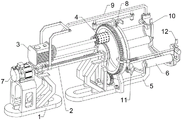
Fig. 1 is a schematic perspective view of a first perspective structure according to the present invention.
Fig. 2 is a perspective view of a second perspective structure according to the present invention.
Fig. 3 is a partial perspective view of the present invention.
Fig. 4 is a schematic perspective view of the moving mechanism of the present invention.
Fig. 5 is a schematic perspective view of the rotating mechanism of the present invention.
Fig. 6 is a schematic partial perspective view of the rotating mechanism of the present invention.
Fig. 7 is a schematic perspective view of the pressing mechanism of the present invention.
Fig. 8 is a schematic view of a partial cross-sectional perspective structure of the pressing mechanism of the present invention.
Fig. 9 is a schematic perspective view of the limiting mechanism of the present invention.
Fig. 10 is a schematic view of a partial cross-sectional perspective structure of the spacing mechanism of the present invention.
Fig. 11 is a schematic perspective view of the clamping mechanism of the present invention.
Fig. 12 is a partially sectioned perspective view of a clamping mechanism of the present invention.
Fig. 13 is a schematic perspective view of the unlocking mechanism of the present invention.
Number designation in the figure: 1. mounting rack, 2, guide rod, 3, driving motor, 4, polishing wheel, 5, connecting rack, 6, roller, 7, moving mechanism, 71, servo motor, 72, bearing frame, 73, screw rod, 74, slide block, 8, rotating mechanism, 81, rotating shaft, 82, spur gear, 83, belt pulley component, 84, mounting frame, 85, toothed rotating frame, 9, pressing mechanism, 91, moving frame, 92, first fixing frame, 93, first spring, 94, lower pressing piece, 95, rotating wheel, 10, limiting mechanism, 101, first guide seat, 102, sliding rod, 103, second spring, 104, second fixing frame, 105, third spring, 106, limiting block, 11, clamping mechanism, 111, rotating shaft seat, 112, rotating frame, 113, clamping plate, 114, fourth spring, 115, clamping plate, 116, clamping groove, 12, unlocking mechanism, 121, connecting column, 122, second guide seat, 123. a sliding plate 124, a fixed block 125, and a fifth spring.
Detailed Description
Embodiments of the present invention will be described in detail below with reference to the accompanying drawings.
Example 1
A polishing device for processing the inner wall of an optical lens cone is disclosed, as shown in figure 1-2, and comprises a mounting frame 1, a guide rod 2, a driving motor 3, a polishing wheel 4, a connecting frame 5, a roller 6, a moving mechanism 7 and a rotating mechanism 8, wherein the front side and the rear side of the upper part of the mounting frame 1 are both connected with the guide rod 2, the mounting frame 1 is welded between the right sides of the guide rod 2, the connecting frame 5 is respectively supported on the ground, the right side of the mounting frame 1 at the right part is welded with the connecting frame 5, the front side and the rear side of the upper part of the connecting frame 5 are rotatably connected with the roller 6, the roller 6 can guide and support the optical lens cone, the driving motor 3 is connected between the guide rods 2 in a sliding manner, the guide rods 2 can guide the driving motor 3, the polishing wheel 4 is arranged on the output shaft of the driving motor 3, the output shaft of the driving motor 3 can drive the polishing wheel 4 to rotate, and the polishing wheel 4 can polish the inner wall of the optical lens cone, a moving mechanism 7 for driving the driving motor 3 to move is arranged between the mounting frame 1 and the connecting frame 5, and a rotating mechanism 8 for driving the optical lens barrel to rotate is arranged on the mounting frame 1 on the right part.
As shown in fig. 1, fig. 2, fig. 4 and fig. 5, the moving mechanism 7 includes a servo motor 71, a bearing bracket 72, a screw rod 73 and a slider 74, the top of the left mounting bracket 1 is connected with the servo motor 71 through a bolt, the top of the right mounting bracket 1 is connected with the bearing bracket 72 through a bolt, the upper rotary of the bearing bracket 72 is connected with the screw rod 73, the left of the screw rod 73 is connected with an output shaft of the servo motor 71, the output shaft of the servo motor 71 rotates to drive the screw rod 73 to rotate, the screw rod 73 is connected with the slider 74 in a threaded manner, the slider 74 is connected with the lower part of the driving motor 3, and the screw rod 73 rotates to drive the driving motor 3 to move through the slider 74.
As shown in fig. 1, 2, 5 and 6, the rotating mechanism 8 includes a rotating shaft 81, a spur gear 82, a belt pulley assembly 83, a mounting frame 84 and a toothed rotating frame 85, the rotating shaft 81 is rotatably connected to the lower portion of the bearing frame 72, the bearing frame 72 can guide the rotating shaft 81, the spur gear 82 is welded to the right portion of the rotating shaft 81, the belt pulley assembly 83 is disposed between the right portion of the screw rod 73 and the rotating shaft 81, the belt pulley assembly 83 is composed of two belt pulleys and a flat belt, the two belt pulleys are respectively connected to the right portion of the screw rod 73 and the rotating shaft 81, then a flat belt is wound between the two belt pulleys, the screw rod 73 rotates to drive the rotating shaft 81 to rotate through the belt pulley component 83, the right part of the right mounting frame 1 is connected with a mounting frame 84 through a bolt, the mounting frame 84 is connected with a toothed rotating frame 85 in a rotating mode, the toothed rotating frame 85 is meshed with the straight gear 82, and the straight gear 82 rotates to drive the toothed rotating frame 85 to rotate.
When people need to polish the inner wall of the optical lens barrel, the device can be used for operation, firstly, the optical lens barrel is placed between the rollers 6, the left side of the optical lens barrel penetrates through the mounting frame 84 and the toothed rotating frame 85, so that the toothed rotating frame 85 clamps the outer wall of the optical lens barrel, then, the driving motor 3 can be started, the output shaft of the driving motor 3 rotates to drive the polishing wheel 4 to rotate, the servo motor 71 is started, the output shaft of the servo motor 71 rotates to drive the screw rod 73 to rotate, the screw rod 73 rotates to drive the driving motor 3 and the polishing wheel 4 to move rightwards through the sliding block 74, the screw rod 73 drives the rotating shaft 81 to rotate through the belt pulley component 83, the rotating shaft 81 drives the straight gear 82 and the toothed rotating frame 85 to rotate, the toothed rotating frame 85 can drive the optical lens barrel to rotate, the optical lens barrel rotates while the polishing wheel 4 polishes the inner wall of the optical lens barrel, so can realize automatic effect of processing the polishing to the optical lens barrel inner wall, also can control servo motor 71's output shaft simultaneously and reverse for lead screw 73 reverses, drives driving motor 3 and throwing aureola 4 through slider 74 and moves left and reset, and it can to close driving motor 3 and servo motor 71 afterwards.
Example 2
In addition to embodiment 1, as shown in fig. 1, 2, 7 and 8, the present invention further includes a pressing mechanism 9 capable of pressing the upper side of the optical barrel, the pressing mechanism 9 includes a moving frame 91, first mount 92, first spring 93, holding down part 94 and runner 95, be equipped with on driving motor 3 and remove frame 91, driving motor 3 moves about and can drive and remove frame 91 and move about, the welding of installing frame 84 top has first mount 92, sliding connection has holding down part 94 on first mount 92, can push down part 94 down when removing frame 91 and moving right, all be equipped with first spring 93 between holding down part 94 bottom left and right sides and the first mount 92, first spring 93 can drive first mount 92 and move and reset, holding down part 94 right part rotary type is connected with runner 95, runner 95 can push down optical lens barrel top, thereby play spacing effect.
Can drive when driving motor 3 moves right and move frame 91 and move right, move frame 91 and move right and when pushing down 94 contacts, can press down 94 down, make first spring 93 compressed, pushing down 94 moves down and drives runner 95 and move down, make runner 95 can laminate with optical lens barrel right part top, and can carry out spacingly to the optical lens barrel top, thereby make things convenient for the optical lens barrel to rotate, so that polishing work is carried out in the polishing, can drive when driving motor 3 moves left and move frame 91 and move left, when moving frame 91 and pushing down 94 separation, under the effect of first spring 93, drive pushing down 94 and move up and reset.
As shown in fig. 1, fig. 2, fig. 9 and fig. 10, the optical lens barrel further includes a limiting mechanism 10 capable of limiting the right end of the optical lens barrel, the limiting mechanism 10 includes a first guide seat 101, a sliding rod 102, a second spring 103, a second fixing frame 104, a third spring 105 and a limiting block 106, the first guide seat 101 is welded on the front side and the rear side of the mounting frame 84, the sliding rod 102 is connected on the first guide seat 101 in a sliding manner, the sliding rod 102 can be guided by the first guide seat 101, the second spring 103 is arranged between the sliding rod 102 and the right portion of the first guide seat 101, the second spring 103 is wound on the sliding rod 102, the second spring 103 can drive the sliding rod 102 to move and reset, the second fixing frame 104 is connected on the front side and the rear side of the right portion of the connecting frame 5, the upper portion of the second fixing frame 104 is connected with the limiting block 106, the second fixing frame 104 can guide the limiting block 106, the right portion of the sliding rod 102 can be inserted into the limiting block 106, the position of the limiting block 106 is limited, and a third spring 105 is arranged between the limiting block 106 and the second fixing frame 104.
Initially, the right part of the sliding rod 102 can be inserted into the stop blocks 106 respectively, the stop blocks 106 are at the sides far away from each other, and the third spring 105 is in a compressed state; when a person passes the optical barrel through the mounting frame 84, the optical barrel moves leftward to contact the left side of the slide lever 102, and drives the sliding rod 102 to move leftwards, at this time, the second spring 103 is compressed, and the sliding rod 102 moves leftwards to be disengaged from the stopper 106, under the action of the third spring 105, the limiting block 106 is driven to move towards the side close to each other inwards, so that the limiting block 106 can limit the right end of the optical lens barrel, therefore, in the process of polishing the inner wall of the optical lens barrel, the optical lens barrel can be prevented from sliding out rightwards, the stability of the optical lens barrel can be improved, and if the polishing is finished, the optical lens barrel can be taken out rightwards, and the limit blocks 106 are moved to the side far away from each other to be reset, so that the third spring 105 is compressed, then, under the action of the second spring 103, the slide lever 102 is reset to the right to limit the position of the stopper 106 again.
As shown in fig. 1, fig. 2, fig. 11 and fig. 12, the optical lens barrel outer wall clamping device further includes a clamping mechanism 11 capable of clamping the optical lens barrel outer wall, the clamping mechanism 11 includes a rotating shaft seat 111, a rotating frame 112, a clamping plate 113, a fourth spring 114 and a clamping plate 115, the three rotating shaft seats 111 are welded on the right portion of the toothed rotating frame 85, the rotating frame 112 is rotatably connected on the rotating shaft seat 111, the rotating shaft seat 111 can guide the rotating frame 112, the clamping plate 113 is slidably connected on the rotating frame 112, the clamping plate 113 can clamp the optical lens barrel outer wall, the fourth spring 114 is arranged between the clamping plate 113 and the rotating frame 112, the fourth spring 114 can drive the clamping plate 113 to move and reset, the clamping plate 115 is welded on the rotating frame 112, the three clamping grooves 116 are formed on the right portion of the toothed rotating frame 85, and the clamping plate 115 can be clamped in the clamping grooves 116.
After placing optical lens barrel, can carry out the swing to the right with rotating turret 112 respectively, drive cardboard 115 card simultaneously and go into in the draw-in groove 116, then make the laminating of clamp plate 113 and optical lens barrel outer wall, under the effect of fourth spring 114, drive clamp plate 113 and press from both sides tight optical lens barrel, can make optical lens barrel more stable at rotatory in-process like this, avoid optical lens barrel the condition of throwing away to appear, after the completion, can rotate rotating turret 112 and reset, make cardboard 115 and draw-in groove 116 separation, thereby make clamp plate 113 and optical lens barrel outer wall break away from.
As shown in fig. 1, 2 and 13, the unlocking mechanism 12 capable of unlocking is further included, the unlocking mechanism 12 includes a connecting column 121, second guide seats 122 and a sliding plate 123, the second guide seats 122 are welded on the front side and the rear side of the right portion of the connecting frame 5, the sliding plate 123 is connected between the second guide seats 122 in a sliding manner, the second guide seats 122 can guide the sliding plate 123, the connecting column 121 is welded on the right portion of the limiting block 106, and the connecting column 121 can be pushed by the downward movement of the sliding plate 123.
The connecting frame further comprises a fifth spring 125 and a fixed block 124, the fixed block 124 is welded in the middle of the right portion of the connecting frame 5, and the fifth spring 125 is arranged between the top of the fixed block 124 and the sliding plate 123.
When the limiting block 106 is required to move towards the side away from each other, the sliding plate 123 can be pressed downwards, so that the fifth spring 125 is compressed, the sliding plate 123 moves downwards to push the connecting column 121 to move towards the side away from each other, and then the limiting block 106 moves towards the side away from each other, so that the sliding rod 102 is inserted into the limiting block 106 again, then the sliding plate 123 is loosened, and the sliding plate 123 is driven to move upwards to reset under the action of the fifth spring 125.
The present application is described in detail above, and specific examples are applied herein to explain the principles and embodiments of the present application, and the descriptions of the above examples are only used to help understand the method and the core idea of the present application; meanwhile, for a person skilled in the art, according to the idea of the present application, there may be variations in the specific embodiments and the application scope, and in summary, the content of the present specification should not be construed as a limitation to the present application.
Claims (8)
1. The utility model provides an optical lens barrel inner wall processing burnishing device, is including mounting bracket (1), guide bar (2), driving motor (3) and throwing aureola (4), both sides all are connected with guide bar (2) around mounting bracket (1) upper portion, also has mounting bracket (1) between guide bar (2) the right side welding, and slidingtype connection has driving motor (3) between guide bar (2), is equipped with on the output shaft of driving motor (3) and throws aureola (4), its characterized in that: still including link (5), cylinder (6), moving mechanism (7) and rotary mechanism (8), the welding of mounting bracket (1) right side of right part has link (5), both sides equal rotary type is connected with cylinder (6) around link (5) upper portion, be equipped with between mounting bracket (1) and link (5) and be used for driving motor (3) and carry out moving mechanism (7) that remove, be equipped with on mounting bracket (1) of right part and be used for driving optical lens barrel and carry out rotatory rotary mechanism (8).
2. The apparatus for processing and polishing the inner wall of an optical lens barrel according to claim 1, wherein: moving mechanism (7) is including servo motor (71), bearing frame (72), lead screw (73) and slider (74), there is servo motor (71) at mounting bracket (1) top of left part through bolted connection, there is bearing frame (72) at mounting bracket (1) top of right part through bolted connection, bearing frame (72) upper portion rotary type is connected with lead screw (73), the output shaft of lead screw (73) left part and servo motor (71), threaded connection has slider (74) on lead screw (73), slider (74) and driving motor (3) sub-unit connection.
3. The apparatus for processing and polishing the inner wall of an optical lens barrel according to claim 2, wherein: the rotating mechanism (8) comprises a rotating shaft (81), a straight gear (82), a belt pulley assembly (83), a mounting frame (84) and a toothed rotating frame (85), the lower portion of a bearing frame (72) is rotatably connected with the rotating shaft (81), the straight gear (82) is welded on the right portion of the rotating shaft (81), the belt pulley assembly (83) is arranged between the right portion of a screw rod (73) and the rotating shaft (81), the belt pulley assembly (83) consists of two belt pulleys and a flat belt, the two belt pulleys are respectively connected to the right portion of the screw rod (73) and the rotating shaft (81), then the flat belt is wound between the two belt pulleys, the right portion of a mounting frame (1) on the right portion is connected with the mounting frame (84) through bolts, the mounting frame (84) is rotatably connected with the toothed rotating frame (85), and the toothed rotating frame (85) is meshed with the straight gear (82).
4. The apparatus for processing and polishing the inner wall of an optical lens barrel according to claim 3, wherein: still including pushing down mechanism (9) that can push down optical lens barrel top, pushing down mechanism (9) are equipped with on driving motor (3) and move frame (91) including removing frame (91), first mount (92), first spring (93), push down piece (94) and runner (95), mounting frame (84) top welding has first mount (92), sliding type is connected with push down piece (94) on first mount (92), all be equipped with between push down piece (94) bottom left and right sides and first mount (92) first spring (93), push down piece (94) right part rotary type is connected with runner (95).
5. The apparatus for processing and polishing the inner wall of an optical lens barrel according to claim 4, wherein: the optical lens barrel is characterized by further comprising a limiting mechanism (10) capable of limiting the right end of the optical lens barrel, wherein the limiting mechanism (10) comprises a first guide seat (101), a sliding rod (102), a second spring (103), a second fixing frame (104), a third spring (105) and a limiting block (106), the first guide seat (101) is welded on the front side and the rear side of the installation frame (84), the sliding rod (102) is connected on the first guide seat (101) in a sliding mode, the second spring (103) is arranged between the sliding rod (102) and the right portion of the first guide seat (101), the second spring (103) is wound on the sliding rod (102), the second fixing frame (104) is connected on the front side and the rear side of the right portion of the connecting frame (5), the limiting block (106) is connected on the upper portion of the second fixing frame (104) in a sliding mode, and the third spring (105) is arranged between the limiting block (106) and the second fixing frame (104).
6. The apparatus for processing and polishing the inner wall of an optical lens barrel according to claim 5, wherein: still including clamping mechanism (11) that can press from both sides tight to optical lens section of thick bamboo outer wall, clamping mechanism (11) are including pivot seat (111), rotating turret (112), pinch-off blades (113), fourth spring (114) and cardboard (115), take tooth rotating frame (85) right part welding to have three pivot seat (111), equal rotary type is connected with rotating turret (112) on pivot seat (111), all sliding type is connected with pinch-off blades (113) on rotating turret (112), all be equipped with fourth spring (114) between pinch-off blades (113) and rotating turret (112), all weld cardboard (115) on rotating turret (112), take tooth rotating frame (85) right part to open there are three draw-in groove (116), cardboard (115) can block in draw-in groove (116).
7. The apparatus for processing and polishing the inner wall of an optical lens barrel according to claim 6, wherein: the unlocking mechanism (12) capable of unlocking is further included, the unlocking mechanism (12) comprises a connecting column (121), second guide seats (122) and a sliding plate (123), the second guide seats (122) are welded on the front side and the rear side of the right portion of the connecting frame (5), the sliding plate (123) is connected between the second guide seats (122) in a sliding mode, and the connecting column (121) is welded on the right portion of the limiting block (106).
8. The apparatus for processing and polishing the inner wall of an optical lens barrel according to claim 7, wherein: the connecting frame further comprises a fifth spring (125) and a fixed block (124), the fixed block (124) is welded in the middle of the right portion of the connecting frame (5), and the fifth spring (125) is arranged between the top of the fixed block (124) and the sliding plate (123).
Priority Applications (1)
| Application Number | Priority Date | Filing Date | Title |
|---|---|---|---|
| CN202210839531.4A CN115091346A (en) | 2022-07-18 | 2022-07-18 | Optical lens barrel inner wall processing and polishing device |
Applications Claiming Priority (1)
| Application Number | Priority Date | Filing Date | Title |
|---|---|---|---|
| CN202210839531.4A CN115091346A (en) | 2022-07-18 | 2022-07-18 | Optical lens barrel inner wall processing and polishing device |
Publications (1)
| Publication Number | Publication Date |
|---|---|
| CN115091346A true CN115091346A (en) | 2022-09-23 |
Family
ID=83297954
Family Applications (1)
| Application Number | Title | Priority Date | Filing Date |
|---|---|---|---|
| CN202210839531.4A Withdrawn CN115091346A (en) | 2022-07-18 | 2022-07-18 | Optical lens barrel inner wall processing and polishing device |
Country Status (1)
| Country | Link |
|---|---|
| CN (1) | CN115091346A (en) |
Cited By (1)
| Publication number | Priority date | Publication date | Assignee | Title |
|---|---|---|---|---|
| CN116276600A (en) * | 2023-05-19 | 2023-06-23 | 安徽洛希尔螺纹技术有限公司 | Polishing machine for machining thread rolling wheel |
-
2022
- 2022-07-18 CN CN202210839531.4A patent/CN115091346A/en not_active Withdrawn
Cited By (2)
| Publication number | Priority date | Publication date | Assignee | Title |
|---|---|---|---|---|
| CN116276600A (en) * | 2023-05-19 | 2023-06-23 | 安徽洛希尔螺纹技术有限公司 | Polishing machine for machining thread rolling wheel |
| CN116276600B (en) * | 2023-05-19 | 2023-08-04 | 安徽洛希尔螺纹技术有限公司 | Polishing machine for machining thread rolling wheel |
Similar Documents
| Publication | Publication Date | Title |
|---|---|---|
| CN112247820B (en) | Solid wood cylinder polishing equipment for furniture production | |
| CN115091346A (en) | Optical lens barrel inner wall processing and polishing device | |
| CN112428038A (en) | Sanding and polishing equipment for steel basin | |
| CN114378584A (en) | Cutting device is used in metal pipeline production | |
| CN115446681A (en) | Automobile rear axle housing polishing equipment | |
| CN116871758A (en) | Intelligent aluminum alloy profile machining equipment | |
| CN114447397A (en) | New forms of energy battery processing is with location closing cap device | |
| CN116572098B (en) | Double-end-face grinding machine for bearing treatment | |
| CN117300771A (en) | Surface treatment equipment for cotton spinning steel collar | |
| CN112476087A (en) | Based on quick grinding device of wooden toy gyro wheel | |
| CN116237853A (en) | Labor insurance shoe sole processor | |
| CN113399511B (en) | Steel bar bending equipment for industrial manufacturing | |
| CN109623951A (en) | A kind of timber automatic transverse cutting machine | |
| CN114850908A (en) | Rapid positioning and clamping method for metal cutting | |
| CN113910017A (en) | Copper-nickel-tin alloy pipe production and processing equipment and production process thereof | |
| CN112192330A (en) | Polishing device for resistor machining | |
| CN214445412U (en) | Automatic ball round pin material limit descaling machine | |
| CN112171427A (en) | Be used for lens edge machining and forming equipment | |
| CN210518042U (en) | Motor rotor processing equipment | |
| CN113770895B (en) | Spot-wear processing is with polishing equipment to table tennis racket surface | |
| CN220783330U (en) | Lens adsorption and transportation manipulator for repairing and grinding lens of camera | |
| CN114905361B (en) | Section processingequipment for building materials cutting | |
| CN219504716U (en) | Turnover mechanism of automobile part detection tool | |
| CN116276600B (en) | Polishing machine for machining thread rolling wheel | |
| CN114193288B (en) | Arc panel equipment of polishing for furniture production |
Legal Events
| Date | Code | Title | Description |
|---|---|---|---|
| PB01 | Publication | ||
| PB01 | Publication | ||
| SE01 | Entry into force of request for substantive examination | ||
| SE01 | Entry into force of request for substantive examination | ||
| WW01 | Invention patent application withdrawn after publication |
Application publication date: 20220923 |
|
| WW01 | Invention patent application withdrawn after publication |