CN115087413A - Method for operating a surgical microscope and surgical microscope - Google Patents
Method for operating a surgical microscope and surgical microscope Download PDFInfo
- Publication number
- CN115087413A CN115087413A CN202080091106.0A CN202080091106A CN115087413A CN 115087413 A CN115087413 A CN 115087413A CN 202080091106 A CN202080091106 A CN 202080091106A CN 115087413 A CN115087413 A CN 115087413A
- Authority
- CN
- China
- Prior art keywords
- camera
- amount
- display
- user
- body part
- Prior art date
- Legal status (The legal status is an assumption and is not a legal conclusion. Google has not performed a legal analysis and makes no representation as to the accuracy of the status listed.)
- Pending
Links
- 238000000034 method Methods 0.000 title claims abstract description 41
- 230000008859 change Effects 0.000 claims abstract description 47
- 230000007423 decrease Effects 0.000 claims abstract description 25
- 238000012545 processing Methods 0.000 claims description 10
- 239000011521 glass Substances 0.000 claims description 6
- 238000001514 detection method Methods 0.000 claims description 5
- 238000013519 translation Methods 0.000 claims description 3
- 230000003247 decreasing effect Effects 0.000 abstract description 5
- 210000003128 head Anatomy 0.000 description 18
- 230000004886 head movement Effects 0.000 description 6
- 238000012986 modification Methods 0.000 description 2
- 230000004048 modification Effects 0.000 description 2
- 230000008569 process Effects 0.000 description 2
- 238000001454 recorded image Methods 0.000 description 2
- 238000001356 surgical procedure Methods 0.000 description 2
- 230000005540 biological transmission Effects 0.000 description 1
- 238000012937 correction Methods 0.000 description 1
- 230000010287 polarization Effects 0.000 description 1
- 230000009467 reduction Effects 0.000 description 1
Images


Classifications
-
- A—HUMAN NECESSITIES
- A61—MEDICAL OR VETERINARY SCIENCE; HYGIENE
- A61B—DIAGNOSIS; SURGERY; IDENTIFICATION
- A61B90/00—Instruments, implements or accessories specially adapted for surgery or diagnosis and not covered by any of the groups A61B1/00 - A61B50/00, e.g. for luxation treatment or for protecting wound edges
- A61B90/36—Image-producing devices or illumination devices not otherwise provided for
- A61B90/37—Surgical systems with images on a monitor during operation
-
- G—PHYSICS
- G02—OPTICS
- G02B—OPTICAL ELEMENTS, SYSTEMS OR APPARATUS
- G02B21/00—Microscopes
- G02B21/36—Microscopes arranged for photographic purposes or projection purposes or digital imaging or video purposes including associated control and data processing arrangements
- G02B21/362—Mechanical details, e.g. mountings for the camera or image sensor, housings
-
- A—HUMAN NECESSITIES
- A61—MEDICAL OR VETERINARY SCIENCE; HYGIENE
- A61B—DIAGNOSIS; SURGERY; IDENTIFICATION
- A61B90/00—Instruments, implements or accessories specially adapted for surgery or diagnosis and not covered by any of the groups A61B1/00 - A61B50/00, e.g. for luxation treatment or for protecting wound edges
- A61B90/20—Surgical microscopes characterised by non-optical aspects
- A61B90/25—Supports therefor
-
- A—HUMAN NECESSITIES
- A61—MEDICAL OR VETERINARY SCIENCE; HYGIENE
- A61B—DIAGNOSIS; SURGERY; IDENTIFICATION
- A61B90/00—Instruments, implements or accessories specially adapted for surgery or diagnosis and not covered by any of the groups A61B1/00 - A61B50/00, e.g. for luxation treatment or for protecting wound edges
- A61B90/36—Image-producing devices or illumination devices not otherwise provided for
- A61B90/361—Image-producing devices, e.g. surgical cameras
-
- G—PHYSICS
- G02—OPTICS
- G02B—OPTICAL ELEMENTS, SYSTEMS OR APPARATUS
- G02B21/00—Microscopes
- G02B21/0004—Microscopes specially adapted for specific applications
- G02B21/0012—Surgical microscopes
-
- G—PHYSICS
- G02—OPTICS
- G02B—OPTICAL ELEMENTS, SYSTEMS OR APPARATUS
- G02B21/00—Microscopes
- G02B21/36—Microscopes arranged for photographic purposes or projection purposes or digital imaging or video purposes including associated control and data processing arrangements
- G02B21/364—Projection microscopes
-
- G—PHYSICS
- G02—OPTICS
- G02B—OPTICAL ELEMENTS, SYSTEMS OR APPARATUS
- G02B21/00—Microscopes
- G02B21/36—Microscopes arranged for photographic purposes or projection purposes or digital imaging or video purposes including associated control and data processing arrangements
- G02B21/365—Control or image processing arrangements for digital or video microscopes
-
- G—PHYSICS
- G02—OPTICS
- G02B—OPTICAL ELEMENTS, SYSTEMS OR APPARATUS
- G02B21/00—Microscopes
- G02B21/36—Microscopes arranged for photographic purposes or projection purposes or digital imaging or video purposes including associated control and data processing arrangements
- G02B21/368—Microscopes arranged for photographic purposes or projection purposes or digital imaging or video purposes including associated control and data processing arrangements details of associated display arrangements, e.g. mounting of LCD monitor
-
- G—PHYSICS
- G02—OPTICS
- G02B—OPTICAL ELEMENTS, SYSTEMS OR APPARATUS
- G02B27/00—Optical systems or apparatus not provided for by any of the groups G02B1/00 - G02B26/00, G02B30/00
- G02B27/01—Head-up displays
- G02B27/017—Head mounted
- G02B27/0172—Head mounted characterised by optical features
-
- G—PHYSICS
- G06—COMPUTING; CALCULATING OR COUNTING
- G06F—ELECTRIC DIGITAL DATA PROCESSING
- G06F3/00—Input arrangements for transferring data to be processed into a form capable of being handled by the computer; Output arrangements for transferring data from processing unit to output unit, e.g. interface arrangements
- G06F3/01—Input arrangements or combined input and output arrangements for interaction between user and computer
- G06F3/011—Arrangements for interaction with the human body, e.g. for user immersion in virtual reality
- G06F3/012—Head tracking input arrangements
-
- G—PHYSICS
- G06—COMPUTING; CALCULATING OR COUNTING
- G06F—ELECTRIC DIGITAL DATA PROCESSING
- G06F3/00—Input arrangements for transferring data to be processed into a form capable of being handled by the computer; Output arrangements for transferring data from processing unit to output unit, e.g. interface arrangements
- G06F3/01—Input arrangements or combined input and output arrangements for interaction between user and computer
- G06F3/011—Arrangements for interaction with the human body, e.g. for user immersion in virtual reality
- G06F3/013—Eye tracking input arrangements
-
- G—PHYSICS
- G06—COMPUTING; CALCULATING OR COUNTING
- G06F—ELECTRIC DIGITAL DATA PROCESSING
- G06F3/00—Input arrangements for transferring data to be processed into a form capable of being handled by the computer; Output arrangements for transferring data from processing unit to output unit, e.g. interface arrangements
- G06F3/01—Input arrangements or combined input and output arrangements for interaction between user and computer
- G06F3/017—Gesture based interaction, e.g. based on a set of recognized hand gestures
-
- G—PHYSICS
- G06—COMPUTING; CALCULATING OR COUNTING
- G06T—IMAGE DATA PROCESSING OR GENERATION, IN GENERAL
- G06T7/00—Image analysis
- G06T7/20—Analysis of motion
- G06T7/285—Analysis of motion using a sequence of stereo image pairs
-
- H—ELECTRICITY
- H04—ELECTRIC COMMUNICATION TECHNIQUE
- H04N—PICTORIAL COMMUNICATION, e.g. TELEVISION
- H04N13/00—Stereoscopic video systems; Multi-view video systems; Details thereof
- H04N13/20—Image signal generators
- H04N13/204—Image signal generators using stereoscopic image cameras
- H04N13/239—Image signal generators using stereoscopic image cameras using two 2D image sensors having a relative position equal to or related to the interocular distance
-
- H—ELECTRICITY
- H04—ELECTRIC COMMUNICATION TECHNIQUE
- H04N—PICTORIAL COMMUNICATION, e.g. TELEVISION
- H04N13/00—Stereoscopic video systems; Multi-view video systems; Details thereof
- H04N13/20—Image signal generators
- H04N13/296—Synchronisation thereof; Control thereof
-
- H—ELECTRICITY
- H04—ELECTRIC COMMUNICATION TECHNIQUE
- H04N—PICTORIAL COMMUNICATION, e.g. TELEVISION
- H04N13/00—Stereoscopic video systems; Multi-view video systems; Details thereof
- H04N13/30—Image reproducers
- H04N13/332—Displays for viewing with the aid of special glasses or head-mounted displays [HMD]
-
- H—ELECTRICITY
- H04—ELECTRIC COMMUNICATION TECHNIQUE
- H04N—PICTORIAL COMMUNICATION, e.g. TELEVISION
- H04N23/00—Cameras or camera modules comprising electronic image sensors; Control thereof
- H04N23/50—Constructional details
- H04N23/54—Mounting of pick-up tubes, electronic image sensors, deviation or focusing coils
-
- H—ELECTRICITY
- H04—ELECTRIC COMMUNICATION TECHNIQUE
- H04N—PICTORIAL COMMUNICATION, e.g. TELEVISION
- H04N23/00—Cameras or camera modules comprising electronic image sensors; Control thereof
- H04N23/60—Control of cameras or camera modules
- H04N23/62—Control of parameters via user interfaces
-
- H—ELECTRICITY
- H04—ELECTRIC COMMUNICATION TECHNIQUE
- H04N—PICTORIAL COMMUNICATION, e.g. TELEVISION
- H04N23/00—Cameras or camera modules comprising electronic image sensors; Control thereof
- H04N23/60—Control of cameras or camera modules
- H04N23/69—Control of means for changing angle of the field of view, e.g. optical zoom objectives or electronic zooming
-
- H—ELECTRICITY
- H04—ELECTRIC COMMUNICATION TECHNIQUE
- H04N—PICTORIAL COMMUNICATION, e.g. TELEVISION
- H04N23/00—Cameras or camera modules comprising electronic image sensors; Control thereof
- H04N23/60—Control of cameras or camera modules
- H04N23/695—Control of camera direction for changing a field of view, e.g. pan, tilt or based on tracking of objects
-
- A—HUMAN NECESSITIES
- A61—MEDICAL OR VETERINARY SCIENCE; HYGIENE
- A61B—DIAGNOSIS; SURGERY; IDENTIFICATION
- A61B17/00—Surgical instruments, devices or methods, e.g. tourniquets
- A61B2017/00017—Electrical control of surgical instruments
- A61B2017/00203—Electrical control of surgical instruments with speech control or speech recognition
-
- A—HUMAN NECESSITIES
- A61—MEDICAL OR VETERINARY SCIENCE; HYGIENE
- A61B—DIAGNOSIS; SURGERY; IDENTIFICATION
- A61B17/00—Surgical instruments, devices or methods, e.g. tourniquets
- A61B2017/00017—Electrical control of surgical instruments
- A61B2017/00207—Electrical control of surgical instruments with hand gesture control or hand gesture recognition
-
- A—HUMAN NECESSITIES
- A61—MEDICAL OR VETERINARY SCIENCE; HYGIENE
- A61B—DIAGNOSIS; SURGERY; IDENTIFICATION
- A61B17/00—Surgical instruments, devices or methods, e.g. tourniquets
- A61B2017/00017—Electrical control of surgical instruments
- A61B2017/00216—Electrical control of surgical instruments with eye tracking or head position tracking control
-
- A—HUMAN NECESSITIES
- A61—MEDICAL OR VETERINARY SCIENCE; HYGIENE
- A61B—DIAGNOSIS; SURGERY; IDENTIFICATION
- A61B90/00—Instruments, implements or accessories specially adapted for surgery or diagnosis and not covered by any of the groups A61B1/00 - A61B50/00, e.g. for luxation treatment or for protecting wound edges
- A61B90/36—Image-producing devices or illumination devices not otherwise provided for
- A61B2090/364—Correlation of different images or relation of image positions in respect to the body
- A61B2090/368—Correlation of different images or relation of image positions in respect to the body changing the image on a display according to the operator's position
-
- A—HUMAN NECESSITIES
- A61—MEDICAL OR VETERINARY SCIENCE; HYGIENE
- A61B—DIAGNOSIS; SURGERY; IDENTIFICATION
- A61B90/00—Instruments, implements or accessories specially adapted for surgery or diagnosis and not covered by any of the groups A61B1/00 - A61B50/00, e.g. for luxation treatment or for protecting wound edges
- A61B90/36—Image-producing devices or illumination devices not otherwise provided for
- A61B90/37—Surgical systems with images on a monitor during operation
- A61B2090/371—Surgical systems with images on a monitor during operation with simultaneous use of two cameras
-
- A—HUMAN NECESSITIES
- A61—MEDICAL OR VETERINARY SCIENCE; HYGIENE
- A61B—DIAGNOSIS; SURGERY; IDENTIFICATION
- A61B90/00—Instruments, implements or accessories specially adapted for surgery or diagnosis and not covered by any of the groups A61B1/00 - A61B50/00, e.g. for luxation treatment or for protecting wound edges
- A61B90/36—Image-producing devices or illumination devices not otherwise provided for
- A61B90/37—Surgical systems with images on a monitor during operation
- A61B2090/372—Details of monitor hardware
-
- A—HUMAN NECESSITIES
- A61—MEDICAL OR VETERINARY SCIENCE; HYGIENE
- A61B—DIAGNOSIS; SURGERY; IDENTIFICATION
- A61B90/00—Instruments, implements or accessories specially adapted for surgery or diagnosis and not covered by any of the groups A61B1/00 - A61B50/00, e.g. for luxation treatment or for protecting wound edges
- A61B90/50—Supports for surgical instruments, e.g. articulated arms
- A61B2090/502—Headgear, e.g. helmet, spectacles
-
- A—HUMAN NECESSITIES
- A61—MEDICAL OR VETERINARY SCIENCE; HYGIENE
- A61M—DEVICES FOR INTRODUCING MEDIA INTO, OR ONTO, THE BODY; DEVICES FOR TRANSDUCING BODY MEDIA OR FOR TAKING MEDIA FROM THE BODY; DEVICES FOR PRODUCING OR ENDING SLEEP OR STUPOR
- A61M2205/00—General characteristics of the apparatus
- A61M2205/50—General characteristics of the apparatus with microprocessors or computers
- A61M2205/502—User interfaces, e.g. screens or keyboards
- A61M2205/507—Head Mounted Displays [HMD]
-
- G—PHYSICS
- G02—OPTICS
- G02B—OPTICAL ELEMENTS, SYSTEMS OR APPARATUS
- G02B27/00—Optical systems or apparatus not provided for by any of the groups G02B1/00 - G02B26/00, G02B30/00
- G02B27/01—Head-up displays
- G02B27/0101—Head-up displays characterised by optical features
- G02B2027/0138—Head-up displays characterised by optical features comprising image capture systems, e.g. camera
-
- G—PHYSICS
- G02—OPTICS
- G02B—OPTICAL ELEMENTS, SYSTEMS OR APPARATUS
- G02B27/00—Optical systems or apparatus not provided for by any of the groups G02B1/00 - G02B26/00, G02B30/00
- G02B27/01—Head-up displays
- G02B27/0101—Head-up displays characterised by optical features
- G02B2027/014—Head-up displays characterised by optical features comprising information/image processing systems
-
- G—PHYSICS
- G02—OPTICS
- G02B—OPTICAL ELEMENTS, SYSTEMS OR APPARATUS
- G02B27/00—Optical systems or apparatus not provided for by any of the groups G02B1/00 - G02B26/00, G02B30/00
- G02B27/01—Head-up displays
- G02B27/017—Head mounted
- G02B2027/0178—Eyeglass type
-
- G—PHYSICS
- G02—OPTICS
- G02B—OPTICAL ELEMENTS, SYSTEMS OR APPARATUS
- G02B27/00—Optical systems or apparatus not provided for by any of the groups G02B1/00 - G02B26/00, G02B30/00
- G02B27/01—Head-up displays
- G02B27/0179—Display position adjusting means not related to the information to be displayed
- G02B2027/0187—Display position adjusting means not related to the information to be displayed slaved to motion of at least a part of the body of the user, e.g. head, eye
-
- G—PHYSICS
- G06—COMPUTING; CALCULATING OR COUNTING
- G06T—IMAGE DATA PROCESSING OR GENERATION, IN GENERAL
- G06T2207/00—Indexing scheme for image analysis or image enhancement
- G06T2207/10—Image acquisition modality
- G06T2207/10004—Still image; Photographic image
- G06T2207/10012—Stereo images
-
- G—PHYSICS
- G06—COMPUTING; CALCULATING OR COUNTING
- G06T—IMAGE DATA PROCESSING OR GENERATION, IN GENERAL
- G06T2207/00—Indexing scheme for image analysis or image enhancement
- G06T2207/10—Image acquisition modality
- G06T2207/10056—Microscopic image
-
- G—PHYSICS
- G06—COMPUTING; CALCULATING OR COUNTING
- G06T—IMAGE DATA PROCESSING OR GENERATION, IN GENERAL
- G06T2207/00—Indexing scheme for image analysis or image enhancement
- G06T2207/30—Subject of image; Context of image processing
- G06T2207/30004—Biomedical image processing
-
- G—PHYSICS
- G06—COMPUTING; CALCULATING OR COUNTING
- G06T—IMAGE DATA PROCESSING OR GENERATION, IN GENERAL
- G06T2207/00—Indexing scheme for image analysis or image enhancement
- G06T2207/30—Subject of image; Context of image processing
- G06T2207/30196—Human being; Person
-
- G—PHYSICS
- G06—COMPUTING; CALCULATING OR COUNTING
- G06T—IMAGE DATA PROCESSING OR GENERATION, IN GENERAL
- G06T2207/00—Indexing scheme for image analysis or image enhancement
- G06T2207/30—Subject of image; Context of image processing
- G06T2207/30244—Camera pose
-
- H—ELECTRICITY
- H04—ELECTRIC COMMUNICATION TECHNIQUE
- H04N—PICTORIAL COMMUNICATION, e.g. TELEVISION
- H04N23/00—Cameras or camera modules comprising electronic image sensors; Control thereof
- H04N23/60—Control of cameras or camera modules
- H04N23/66—Remote control of cameras or camera parts, e.g. by remote control devices
Abstract
A method of operating a surgical microscope includes detecting an amount of movement of a body part of a user, and performing movement of a camera and a change in magnification based on the detected movement of the body part. The amounts of movement and variations decrease with increasing magnification provided by the surgical microscope, decrease with decreasing distance of the user's body part from the display, and decrease with decreasing distance of the camera from the camera's field of view.
Description
Technical Field
The present invention relates to a surgical microscope and a method of operating such a surgical microscope.
Background
A conventional surgical microscope includes a microscope body that includes microscope optics with two eyepieces. The microscope body is carried by a support having a hinged structure such that the microscope optics can be positioned and repositioned relative to the object by translational and rotational movement. For example, a user viewing the eyepiece initiates these movements by applying force to the microscope body with his hand. Such surgical microscopes require the user to permanently observe the eyepiece, which is tiring and may, for example, cause pain to the user's neck. Furthermore, the user needs his hand to reposition the microscope, which has to put aside the currently used surgical tools, interrupting the surgical procedure.
Newer surgical microscopes include a camera for recording images of the intraoperative object, and a display for displaying the recorded images to the microscope user. Because the viewing eyepiece is no longer needed, the user can perform the procedure with a convenient head position and view the image on the display. Also, the supports of these microscopes may include actuators for positioning the articulated joints of the supports so that the camera is positioned at a desired position in space in a desired orientation. The desired position and orientation may be entered into the surgical microscope in various ways. For example, WO 2015/151447 a1 discloses a surgical microscope in which the direction of the user's gaze and the movement of the user's head are detected to determine a new position of the camera. The actuators of the support are then operated to reposition the camera according to the detected gaze direction and head movement.
The above technique has significant advantages over conventional surgical microscopes with eyepieces. Also, it has been found that the process of positioning the camera can be improved.
Disclosure of Invention
The present invention has been achieved by taking the above considerations into consideration, and an object of the present invention is to provide a surgical microscope and a method of operating such a surgical microscope, thereby improving the user experience in operations involving repositioning of a camera.
According to the invention, a surgical microscope comprises at least one camera having a field of view, a support for the at least one camera, wherein the support comprises at least one actuator for positioning the at least one camera relative to an object, and a display configured to display an image recorded by the at least one camera.
According to an embodiment of the present invention, a method of operating a surgical microscope includes detecting an amount of movement of a body part of a user, determining an amount of movement of a camera based on the detected movement of the body part of the user, and moving the camera by the determined amount of movement.
According to embodiments herein, the determined amount of camera movement comprises an amount of translational movement in a direction transverse to a line connecting the camera and the field of view. The amount of camera translation movement is determined in dependence on the detected amount of movement of the body part of the user in a direction parallel to the display. The correlation between the determined amount of camera translational movement and the detected amount of movement of the user's body part in a direction parallel to the display depends on the magnification of the image of the object within the camera field of view displayed on the display, the distance of the user's body part from the display, the distance of the camera from the camera field of view, and the detected amount of movement of the user's body part in a direction parallel to the display.
According to some embodiments, the correlation between the determined amount of camera translational movement and the detected amount of movement of the body part of the user in a direction parallel to the display is configured such that the determined amount of camera translational movement decreases as the magnification of an image of an object within the camera field of view displayed on the display increases.
According to a further embodiment, the correlation between the determined amount of camera translational movement and the detected amount of movement of the user's body part in a direction parallel to the display is configured such that the determined amount of camera translational movement decreases when the distance of the user's body part from the display decreases.
According to a further embodiment, the correlation between the determined amount of camera translational movement and the detected amount of movement of the body part of the user in a direction parallel to the display is configured such that the determined amount of camera translational movement decreases when the distance of the camera from the field of view of the camera decreases.
According to a particular embodiment, the determination of the amount of camera movement is performed such that:
(1) the determined amount of camera translation movement is a first determined amount when:
the magnification of the image of the object within the field of view of the camera displayed on the display is a first magnification,
the user body part is a first body part distance from the display,
the camera is a first camera distance from the field of view of the camera, an
The detected amount of movement of the body part of the user in a direction parallel to the display is a given detected amount;
(2) the determined amount of camera translational movement is a second determined amount less than the first determined amount when:
the magnification of the image of the object displayed within the camera field of view on the display is a second magnification greater than the first magnification,
the distance of the user's body part from the display is the first head distance,
the distance of the camera from the field of view of the camera is the first camera distance, an
The detected amount of movement of the body part of the user in a direction parallel to the display is the given detected amount;
(3) the determined amount of camera translational movement is a third determined amount that is less than the first determined amount when:
the magnification of the image of the object displayed in the field of view of the camera on the display is the first magnification,
the user body part is a second body part distance from the display that is less than the first body part distance,
the distance of the camera from the field of view of the camera is the first camera distance, an
The detected amount of movement of the body part of the user in a direction parallel to the display is the given detected amount; and
(4) the determined amount of camera translational movement is a fourth determined amount that is less than the first determined amount when:
the magnification of the image of the object displayed in the field of view of the camera on the display is the first magnification,
the user body part is at the first body part distance from the display,
the camera is a second camera distance from the field of view of the camera that is less than the first camera distance, an
The detected amount of movement of the body part of the user in a direction parallel to the display is the given detected amount.
According to some embodiments, moving the camera by the determined amount of movement comprises keeping the orientation of the at least one camera constant while moving the camera by the determined amount of translational movement.
According to some embodiments, the determined amount of camera movement comprises an amount of camera rotational movement. The amount of rotational movement of the camera is determined in dependence on the detected amount of rotational movement of the body part of the user. The correlation between the determined amount of camera rotational movement and the detected amount of rotational movement of the user's body part depends on the magnification of the image of the object displayed in the camera field of view on the display, the distance of the user's body part from the display, the distance of the camera from the camera field of view, and the detected amount of rotational movement of the user's body part.
According to some embodiments, the correlation between the determined amount of camera rotational movement and the detected amount of rotational movement of the body part of the user is configured such that the determined amount of camera rotational movement decreases as the magnification of the image of the object displayed within the camera field of view on the display increases.
According to a further embodiment, the correlation between the determined amount of camera rotational movement and the detected amount of rotational movement of the user's body part is configured such that the determined amount of camera rotational movement decreases when the distance of the user's body part from the display decreases.
According to a further embodiment, the correlation between the determined amount of camera rotational movement and the detected amount of rotational movement of the body part of the user is configured such that the determined amount of camera rotational movement decreases when the distance of the camera from the field of view of the camera decreases.
According to a particular embodiment, the determination of the amount of camera movement is performed such that:
(1) the determined amount of camera rotational movement is a first determined amount when:
the magnification of the image of the object within the field of view of the camera displayed on the display is a first magnification,
the user body part is a first body part distance from the display,
the camera is a first camera distance from the field of view of the camera, an
The detected amount of rotational movement of the body part of the user is a given detection amount;
(2) the determined amount of camera rotational movement is a second determined amount less than the first determined amount when:
the magnification of the image of the object displayed within the camera field of view on the display is a second magnification greater than the first magnification,
the distance of the user's body part from the display is the first head distance,
the distance of the camera from the field of view of the camera is the first camera distance, an
The detected amount of rotational movement of the body part of the user is the given detection amount;
(3) the determined amount of camera rotational movement is a third determined amount that is less than the first determined amount when:
the magnification of the image of the object displayed in the field of view of the camera on the display is the first magnification,
the user body part is a second body part distance from the display that is less than the first body part distance,
the distance of the camera from the field of view of the camera is the first camera distance, an
The detected amount of rotational movement of the body part of the user is the given detected amount; and
(4) the determined amount of camera rotational movement is a fourth determined amount that is less than the first determined amount when:
the magnification of the image of the object displayed in the field of view of the camera on the display is the first magnification,
the user body part is at the first body part distance from the display,
the camera is a second camera distance from the field of view of the camera that is less than the first camera distance, an
The detected amount of rotational movement of the body part of the user is the given detected amount.
According to some embodiments, the determined amount of camera movement comprises an amount of camera rotational movement, wherein the determination of the amount of camera movement is further performed such that a portion of the object that is within the field of view of the camera before moving the camera by the determined amount of movement is also within the field of view of the camera when moving the camera by the determined amount of movement is complete. For example, this may cause a change in the direction of the camera field of view without changing the position of an object located at the center of the camera field of view.
According to some embodiments, the method comprises detecting a start command, wherein moving the camera by the determined amount of movement is performed only after the start command has been detected.
Moreover, according to a further embodiment, the method further comprises detecting a stop command, wherein moving the camera is performed only before the stop command has been detected.
According to a further embodiment, a method of operating a surgical microscope includes detecting an amount of movement of a body part of a user, determining an amount of change in magnification of an image based on the detected movement of the body part of the user; and changing the image magnification by the determined image magnification change amount.
According to an embodiment herein, the amount of change in the image magnification is determined depending on the detected amount of movement of the body part of the user in the direction perpendicular to the display.
The correlation between the determined amount of change in image magnification and the detected amount of movement of the body part of the user in the direction perpendicular to the display depends on the magnification of the image of the object within the field of view of the camera displayed on the display, the distance of the body part of the user from the display, the distance of the camera from the field of view of the camera, and the detected amount of movement of the body part of the user in the direction perpendicular to the display.
According to some embodiments, the correlation between the determined amount of change in image magnification and the detected amount of movement of the body part of the user in the direction perpendicular to the display is configured such that the determined amount of change in image magnification decreases as the magnification of the image of the object displayed on the display within the field of view of the camera increases.
According to some embodiments, the correlation between the determined amount of change in image magnification and the detected amount of movement of the body part of the user in the direction perpendicular to the display is configured such that the determined amount of change in image magnification decreases as the distance of the body part of the user from the display decreases.
According to some embodiments, the correlation between the determined amount of change in image magnification and the detected amount of movement of the body part of the user in the direction perpendicular to the display is configured such that the determined amount of change in image magnification decreases as the distance of the camera from the field of view of the camera decreases.
According to a particular embodiment, the determination of the amount of change in the magnification of the image is performed such that:
(1) the determined amount of change in the image magnification is a first determined amount when:
the magnification of the image of the object within the field of view of the camera displayed on the display is a first magnification,
the user body part is a first body part distance from the display,
the camera is a first camera distance from the field of view of the camera, an
The detected amount of movement of the body part of the user in a direction perpendicular to the display is a given detected amount;
(2) the determined amount of change in the image magnification is a second determined amount that is less than the first determined amount when:
the magnification of the image of the object displayed within the camera field of view on the display is a second magnification greater than the first magnification,
the distance of the user's body part from the display is the first body part distance,
the distance of the camera from the field of view of the camera is the first camera distance, an
The detected amount of movement of the body part of the user in a direction perpendicular to the display is the given detected amount;
(3) the determined amount of change in the image magnification is a third determined amount that is less than the first determined amount when:
the magnification of the image of the object displayed in the field of view of the camera on the display is the first magnification,
the user body part is a second body part distance from the display that is less than the first body part distance,
the distance of the camera from the field of view of the camera is the first camera distance, an
The detected amount of movement of the body part of the user in a direction perpendicular to the display is the given detected amount; and
(4) the determined amount of change in the image magnification is a fourth determined amount that is less than the first determined amount when:
the magnification of the image of the object displayed in the field of view of the camera on the display is the first magnification,
the user body part is at the first body part distance from the display,
the camera is a second camera distance from the field of view of the camera that is less than the first camera distance, an
The detected amount of movement of the body part of the user in a direction perpendicular to the display is the given detected amount.
According to some embodiments, the determined amount of image magnification change is an increase in image magnification, and the movement of the user's body part in a direction perpendicular to the display comprises a movement of the user's body part towards the display.
According to some embodiments, the determined amount of image magnification change is an image magnification decrease, and the movement of the user's body part in a direction perpendicular to the display comprises a movement of the user's body part away from the display.
According to some embodiments, the amount of image magnification change is an increase in image magnification, and the image magnification change includes at least one of moving the camera toward the object and increasing the magnification of a zoom lens of the camera.
According to some embodiments, the amount of image magnification change is an image magnification decrease, and the image magnification change includes at least one of moving the camera away from the object and decreasing a magnification of a zoom lens of the camera.
According to some embodiments, the method further comprises detecting a start command, and only after the start command has been detected, performing changing the image magnification by the determined amount of change in the image magnification.
According to some embodiments, the method further comprises detecting a stop command, and only before the stop command has been detected, performing changing the image magnification by the determined amount of change in the image magnification.
According to one embodiment, the start command includes at least one of a voice command issued by the user, a button operation performed by the user, and a user gesture.
According to one embodiment, the stop command includes at least one of a voice command issued by the user, a button operation performed by the user, and a user gesture.
According to some embodiments, the user body part comprises at least one of a user head, a user chest and a user shoulder.
According to some embodiments, the camera is a stereo camera configured to record a pair of stereo images. For example, the at least one camera may comprise two cameras for this purpose.
According to some embodiments, the display is configured to display stereoscopic images. According to some embodiments herein, the display is a head mounted display that may be worn by a user of the surgical microscope. According to other embodiments, the display includes a screen that displays an image obtained by processing the pair of stereoscopic images, and a pair of glasses that are wearable by the user and allow the user to see, with the left eye, a display image obtained by processing a left image of the pair of stereoscopic images and to see, with the right eye, a display image obtained by processing a right image of the pair of stereoscopic images.
According to an embodiment of the invention, the surgical microscope comprises a controller configured to perform the above method.
Drawings
The above and other advantageous features of the present disclosure will become more apparent from the following detailed description of exemplary embodiments with reference to the attached drawings. It should be noted that not all possible embodiments necessarily exhibit each or any of the advantages identified herein.
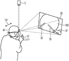
FIG. 1 is a schematic view of a surgical microscope;
FIG. 2 illustrates translational movement of a camera of the surgical microscope of FIG. 1;
FIG. 3 illustrates the camera rotational movement of the surgical microscope of FIG. 1; and
fig. 4 illustrates a change in magnification of the surgical microscope of fig. 1.
Detailed Description
In the exemplary embodiments described below, functionally and structurally similar parts are denoted by similar reference numerals as much as possible. Thus, for an understanding of the features of the individual components of particular embodiments, reference may be made to the description of the summary of the disclosure and other embodiments.
Fig. 1 is a schematic view of a surgical microscope 1. The surgical microscope 1 comprises a microscope body 3 which houses microscope optics 5 comprising a magnifying zoom lens 7 and two cameras 9. The camera 9 records an image of the field of view of the camera 9 in the focal plane 11. The optics 5 are configured to adjust the distance of the focal plane 11 from the microscope body by operating actuators (not shown in fig. 1) controlled by a controller 13 of the surgical microscope 1. The field of view image of the camera 9 recorded by the camera 9 is transmitted to the controller 13. The magnification of an object located in the field of view in the image recorded by the camera 9 can be adjusted by the controller by operating the actuator 15 of the zoom lens 7.
The microscope body 3 is carried by a support 17 comprising a base 19 placed on the floor of the operating room, and a plurality of members 21 connected by joints comprising actuators 23 controlled by the controller 13, so as to position the microscope body 3 within the accessible area of the operating room. The support 17 is configured to be controlled by the controller 13 such that the microscope body 3 performs translational movements in three independent directions and rotational movements around three independent axes. In particular, the actuator 23 of the support may be operated to position the camera 9 such that its field of view coincides with the surgical field 31 when the user 33 of the surgical microscope 1 performs a surgery using a surgical tool 35 held by his hand 37. For this reason, the user observes the operation region 31 by viewing the display showing the image transmitted from the controller 13. The image displayed on the display may be an image obtained by processing an image recorded by the camera 9. The processing of the image may include any image processing operations such as cropping, rotation, contrast enhancement, color correction, and direct display of the recorded image without substantial changes to the image data.
For example, the display may be a flat panel display 39 that may be mounted on the support 17, or a head mounted display 41 worn by the user 33.
The images recorded by the two cameras 9 are pairs of stereo images showing the operating area from different angles. The user may use the head mounted display 41 to view the pair of stereoscopic images such that the user 33 perceives a three-dimensional impression of the surgical area. Similarly, the flat panel display 39 may also be configured to display stereoscopic images, wherein the user 33 would wear appropriate glasses, selecting the display images for transmission to the user's left and right eyes. For example, the flat panel display 39 may alternately display images for the left and right eyes, and the glasses are active shutter glasses that alternately transmit light to the left and right eyes of the user 33. Also, the flat panel display 39 may use different polarization states of the screen pixels to simultaneously display images for the user's left and right eyes, with the user 33 wearing corresponding polarized glasses.
The surgical microscope 1 further includes a sensor 45 that allows the controller to determine the position and orientation of a body part, such as the head 47 of the user 33, relative to the microscope body 3, relative to the field of view 11 of the camera 9, or relative to some other suitable location within the operating room. The sensor 45 may be mounted at any suitable location on the display 39, 41, such as an element of the support 17. Moreover, the sensor may comprise a plurality of sensor elements arranged at a plurality of distributed locations.
The surgical microscope 1 further comprises a sensor 49 which allows the controller 13 to determine the gaze direction of the user 33. In particular, the controller 13 may determine the location within the image displayed on the display 39, 41 at which the user's eyes are pointed. Also, the sensor 49 may be mounted at any suitable location on the display 39, 41 (such as an element of the support 17). Moreover, the sensor may comprise a plurality of sensor elements arranged at a plurality of distributed positions.
The surgical microscope 1 further includes a sensor 51 that allows the controller 13 to receive commands issued by the user 33. For example, the sensor 51 may include a switch that is operated by the user 33 to input a start command and a stop command. Also, the sensor 51 may include a microphone that allows the controller 13 to detect voice commands, such as "start" and "stop".
Fig. 2 illustrates the translational movement of the camera included in the microscope body 3. After the start command, the user performs a translational movement of the head 47. The amount of translational movement of the user's head determines the amount of translational movement of the camera. The main axis 101 of the camera 9 is arranged such that a circular object 103 is arranged at the center of the field of view 11 of the camera 9. An image of the field of view 11 is recorded by the camera 3 and displayed on the display 39. The display 39 is positioned in the user's field of view, as indicated by the cone 105, and the user looks at the center of the image of the object 103, as indicated by the arrow 107.
The reference position of the microscope body 3 is indicated at 111. This reference position 111 may be used to determine the distance between the camera 9 and the field of view 11 of the camera 9.
The reference position of the head 47 of the user 33 is indicated at 113. The reference position 113 may be used to determine the distance between the user's head 47 or eyes and the display 39.
The user 33 may initiate the process of positioning the camera 3 relative to the object 103 by issuing a predefined start command recognized by the surgical microscope. Upon receiving the start command, the surgical microscope tracks the position of the user's head 47 and determines the amount of movement of the user's 47 head until a stop command is detected. In the example shown in fig. 2, the detected movement of head 47 is a translational movement parallel to display 39, as indicated by arrow 114 in fig. 2. The surgical microscope determines a camera movement amount based on the detected user head movement amount, and moves the camera 3 by the determined movement amount. In the example shown in fig. 2, the final movement of the camera is a translational movement, as indicated by arrow 115 in fig. 2.
Fig. 3 illustrates the rotational movement of the camera included in the microscope body 3. After the start command, the user performs the rotational movement of the head 47. The amount of rotational movement of the user's head determines the amount of rotational movement of the camera.
In the example shown in fig. 3, the detected movement of the head 47 is a rotational movement, as indicated by arrow 123 in fig. 3. The surgical microscope determines a camera rotation movement amount based on the detected user head movement amount, and rotates the camera 3 by the determined movement amount. Furthermore, the camera is translated by an amount such that the main axis 101 of the camera is rotated around a center 125 located between the camera 9 and the field of view 11 of the camera 9. The combination of translational and rotational movements produces a combined movement similar to a rotation of the camera about the center 125.
Fig. 4 illustrates the change in image magnification provided by the surgical microscope. The image magnification may be defined as the ratio between the diameter of the image of the object 103 on the display 39 divided by the diameter of the object itself. The image magnification may be increased by moving the camera closer to the object, by zooming in by operating a zoom lens of the camera, or by processing the image recorded by the camera such that the processed image displayed on the display 39, 41 is zoomed in.
In the example shown in fig. 4, the detected movement of the head 47 is a translational movement perpendicular to the display 39, as indicated by arrow 131 in fig. 4. The surgical microscope determines a microscope magnification change amount based on the detected amount of head movement of the user. In the example of fig. 4, it is assumed that the user has moved his head towards the display 39, and this movement causes the magnification provided by the surgical microscope to increase. As is apparent from fig. 4, the object 103 displayed on the display 39 has a larger diameter than in fig. 2 and 3. Similarly, movement of head 47 away from display 39 will result in a reduction in the magnification provided by the surgical microscope.
The amount of change in the microscope optics shown above with reference to fig. 2, 3 and 4 (i.e., the translational movement shown in fig. 2, the rotational movement shown in fig. 3 and the change in magnification shown in fig. 4) depends on the amount of detected head movement of the user. In this context, the correlation between the detected head movement and the resulting change in microscope optics is not constant in all cases. Instead, this correlation depends on the magnification of the image of the object within the camera field of view displayed on the display, the distance of the user's body part from the display, and the distance of the camera from the camera field of view.
In particular, these variations decrease with increasing magnification provided by the surgical microscope, decrease with decreasing distance of the user's body part from the display, and decrease with decreasing distance of the camera from the camera's field of view.
In the above embodiments, the user may control the position and orientation of the camera and the magnification provided by the surgical microscope by performing movements of the head or some other body part. Herein, common start and stop commands may be defined for all three operations, or separate start and/or stop commands for each operation may be defined.
While the present disclosure has been described with respect to certain exemplary embodiments thereof, it is evident that many alternatives, modifications, and variations will be apparent to those skilled in the art. Accordingly, the exemplary embodiments of the disclosure set forth herein are intended to be illustrative, not limiting. Various modifications may be made without departing from the spirit and scope of the disclosure as defined by the appended claims.
Claims (22)
1. A method of operating a surgical microscope, wherein the surgical microscope comprises:
at least one camera having a field of view;
a support for the at least one camera, wherein the support comprises at least one actuator for positioning the at least one camera relative to the object; and
a display configured to display images recorded by the at least one camera;
wherein, the method comprises the following steps:
detecting an amount of movement of a body part of a user;
determining an amount of camera movement based on the detected movement of the user's body part; and
moving the camera by the determined movement amount;
wherein the determined camera movement amount comprises a translational movement amount in a direction transverse to a line connecting the camera and the field of view;
wherein the determination of the camera movement amount is performed such that:
(1) the determined amount of camera translation movement is a first determined amount when:
the magnification of the image of the object within the field of view of the camera displayed on the display is a first magnification,
the user body part is a first body part distance from the display,
the distance of the camera from the field of view of the camera is a first camera distance, an
The detected amount of movement of the body part of the user in a direction parallel to the display is a given detected amount;
(2) the determined amount of camera translational movement is a second determined amount less than the first determined amount when:
the magnification of the image of the object displayed within the camera field of view on the display is a second magnification greater than the first magnification,
the distance of the user's body part from the display is the first head distance,
the distance of the camera from the field of view of the camera is the first camera distance, an
The detected amount of movement of the body part of the user in a direction parallel to the display is the given detected amount;
(3) the determined amount of camera translational movement is a third determined amount that is less than the first determined amount when:
the magnification of the image of the object displayed in the field of view of the camera on the display is the first magnification,
the user body part is a second body part distance from the display that is less than the first body part distance,
the distance of the camera from the field of view of the camera is the first camera distance, an
The detected amount of movement of the body part of the user in a direction parallel to the display is the given detected amount; and
(4) the determined amount of camera translational movement is a fourth determined amount that is less than the first determined amount when:
the magnification of the image of the object within the field of view of the camera displayed on the display is the first magnification,
the user body part is at the first body part distance from the display,
the camera is a second camera distance from the field of view of the camera that is less than the first camera distance, an
The detected amount of movement of the body part of the user in a direction parallel to the display is the given detected amount.
2. The method of claim 1, wherein moving the camera by the determined amount of movement comprises keeping an orientation of the at least one camera constant while moving the camera by the determined amount of translational movement.
3. A method of operating a surgical microscope, wherein the surgical microscope comprises:
at least one camera having a field of view;
a support for the at least one camera, wherein the support comprises at least one actuator for positioning the at least one camera relative to the object; and
a display configured to display images recorded by the at least one camera;
wherein, the method comprises the following steps:
detecting an amount of movement of a body part of a user;
determining a camera movement amount based on the detected movement of the user body part; and
moving the camera by the determined movement amount;
wherein the determined camera movement amount comprises a camera rotational movement amount;
wherein the determination of the camera movement amount is performed such that:
(1) the determined amount of camera rotational movement is a first determined amount when:
the magnification of the image of the object within the field of view of the camera displayed on the display is a first magnification,
the user body part is a first body part distance from the display,
the camera is a first camera distance from the field of view of the camera, an
The detected amount of rotational movement of the body part of the user is a given detection amount;
(2) the determined amount of camera rotational movement is a second determined amount less than the first determined amount when:
the magnification of the image of the object displayed within the camera field of view on the display is a second magnification greater than the first magnification,
the distance of the user's body part from the display is the first head distance,
the distance of the camera from the field of view of the camera is the first camera distance, an
The detected amount of rotational movement of the body part of the user is the given detection amount;
(3) the determined amount of camera rotational movement is a third determined amount that is less than the first determined amount when:
the magnification of the image of the object displayed in the field of view of the camera on the display is the first magnification,
the user body part is a second body part distance from the display that is less than the first body part distance,
the distance of the camera from the field of view of the camera is the first camera distance, an
The detected amount of rotational movement of the body part of the user is the given detection amount; and
(4) the determined amount of camera rotational movement is a fourth determined amount that is less than the first determined amount when:
the magnification of the image of the object displayed in the field of view of the camera on the display is the first magnification,
the distance of the user's body part from the display is the first body part distance,
the camera is a second camera distance from the field of view of the camera that is less than the first camera distance, an
The detected amount of rotational movement of the body part of the user is the given detected amount.
4. The method of one of claims 1 to 3, wherein the determined amount of camera movement comprises an amount of camera rotational movement;
wherein the determination of the camera movement amount is further performed such that a portion of the object that was within the camera field of view before the camera was moved by the determined movement amount is also within the camera field of view when the moving of the camera by the determined movement amount is completed.
5. The method according to one of claims 1 to 4, further comprising detecting a start command,
wherein moving the camera by the determined amount of movement is performed only after the start command has been detected.
6. The method according to one of claims 1 to 5, further comprising detecting a stop command, and
wherein the change of moving the camera is performed only before the stop command has been detected.
7. A method of operating a microscope system, wherein the microscope system comprises:
at least one camera having a zoom lens;
a support for the at least one camera and having at least one actuator for positioning the at least one camera relative to an object; and
a display configured to display an image of an object recorded by the at least one camera using an image magnification;
wherein, the method comprises the following steps:
detecting an amount of movement of a body part of a user;
determining an amount of change in image magnification based on the detected movement of the body part of the user; and
changing the image magnification by the determined image magnification change amount;
wherein the determination of the image magnification change amount is performed such that:
(1) the determined amount of change in the image magnification is a first determined amount when:
the magnification of the image of the object within the field of view of the camera displayed on the display is a first magnification,
the user body part is a first body part distance from the display,
the camera is a first camera distance from the field of view of the camera, an
The detected amount of movement of the body part of the user in a direction perpendicular to the display is a given detected amount;
(2) the determined amount of change in the image magnification is a second determined amount that is less than the first determined amount when:
the magnification of the image of the object displayed within the camera field of view on the display is a second magnification greater than the first magnification,
the user body part is at the first body part distance from the display,
the distance of the camera from the field of view of the camera is the first camera distance, an
The detected amount of movement of the body part of the user in a direction perpendicular to the display is the given detected amount;
(3) the determined amount of change in the image magnification is a third determined amount that is less than the first determined amount when:
the magnification of the image of the object displayed in the field of view of the camera on the display is the first magnification,
the user body part is a second body part distance from the display that is less than the first body part distance,
the distance of the camera from the field of view of the camera is the first camera distance, an
The detected amount of movement of the body part of the user in a direction perpendicular to the display is the given detected amount; and
(4) the determined amount of change in the image magnification is a fourth determined amount that is less than the first determined amount when:
the magnification of the image of the object displayed in the field of view of the camera on the display is the first magnification,
the user body part is at the first body part distance from the display,
the camera is a second camera distance from the field of view of the camera that is less than the first camera distance, an
The detected amount of movement of the body part of the user in a direction perpendicular to the display is the given detected amount.
8. The method of claim 7, wherein the determined amount of image magnification change is an increase in image magnification, and
wherein movement of the user body part in a direction perpendicular to the display comprises movement of the user body part towards the display.
9. The method of claim 7 or 8, wherein the determined amount of change in image magnification is a decrease in image magnification, and
wherein movement of the user body part in a direction perpendicular to the display comprises movement of the user body part away from the display.
10. The method according to one of claims 7 to 9, wherein the image magnification change amount is an image magnification increase, and
wherein the image magnification change comprises at least one of moving the camera towards the object and increasing the magnification of a zoom lens of the camera.
11. The method according to one of claims 7 to 10, wherein the image magnification change amount is an image magnification decrease, and
wherein the image magnification change comprises at least one of moving the camera away from the object and reducing the magnification of a zoom lens of the camera.
12. The method according to one of claims 7 to 11, further comprising detecting a start command,
wherein changing the image magnification by the determined amount of change in the image magnification is performed only after the start command has been detected.
13. The method according to one of claims 7 to 12, further comprising detecting a stop command,
wherein changing the image magnification by the determined amount of change in the image magnification is performed only before the stop command has been detected.
14. The method of claim 5 or 13, wherein the start command comprises at least one of a voice command issued by a user, a button operation performed by a user, and a user gesture.
15. The method of claim 6 or 11, wherein the stop command comprises at least one of a voice command issued by a user, a button operation performed by a user, and a user gesture.
16. The method of one of the claims 1 to 15, wherein the user body part comprises at least one of a user head, a user chest and a user shoulder.
17. The method of one of claims 1 to 16, wherein the at least one camera is a stereo camera.
18. The method of one of the claims 1 to 17, wherein the at least one camera comprises two cameras.
19. The method of one of claims 1 to 18, wherein the display is a display configured to display stereoscopic images.
20. The method of claim 19, wherein the display is a head mounted display.
21. The method of claim 19, wherein the display comprises:
a screen that displays an image obtained by processing images recorded by a first camera and a second camera of the at least one camera; and
a pair of glasses that are wearable by the user and allow the user to see, with his or her left eye, a display image obtained by processing the image recorded by the first camera and to see, with his or her right eye, a display image obtained by processing the image recorded by the second camera.
22. A surgical microscope, comprising:
at least one camera;
a support for the at least one camera and having at least one actuator for positioning the at least one camera relative to an object;
a display configured to display images recorded by the at least one camera; and
a controller configured to perform the method of one of claims 1 to 21 using the surgical microscope.
Applications Claiming Priority (3)
| Application Number | Priority Date | Filing Date | Title |
|---|---|---|---|
| US16/732,126 US11048072B1 (en) | 2019-12-31 | 2019-12-31 | Method of operating a surgical microscope and surgical microscope |
| US16/732126 | 2019-12-31 | ||
| PCT/EP2020/087976 WO2021136777A1 (en) | 2019-12-31 | 2020-12-29 | Method of operating a surgical microscope and surgical microscope |
Publications (1)
| Publication Number | Publication Date |
|---|---|
| CN115087413A true CN115087413A (en) | 2022-09-20 |
Family
ID=74181166
Family Applications (1)
| Application Number | Title | Priority Date | Filing Date |
|---|---|---|---|
| CN202080091106.0A Pending CN115087413A (en) | 2019-12-31 | 2020-12-29 | Method for operating a surgical microscope and surgical microscope |
Country Status (5)
| Country | Link |
|---|---|
| US (2) | US11048072B1 (en) |
| EP (1) | EP4084729A1 (en) |
| JP (1) | JP2023509038A (en) |
| CN (1) | CN115087413A (en) |
| WO (1) | WO2021136777A1 (en) |
Families Citing this family (2)
| Publication number | Priority date | Publication date | Assignee | Title |
|---|---|---|---|---|
| JP2021145788A (en) * | 2020-03-17 | 2021-09-27 | ソニー・オリンパスメディカルソリューションズ株式会社 | Control unit and medical observation system |
| US11743579B2 (en) * | 2020-03-17 | 2023-08-29 | Sony Olympus Medical Solutions Inc. | Control device and medical observation system |
Family Cites Families (9)
| Publication number | Priority date | Publication date | Assignee | Title |
|---|---|---|---|---|
| US5825982A (en) | 1995-09-15 | 1998-10-20 | Wright; James | Head cursor control interface for an automated endoscope system for optimal positioning |
| DE10335644B9 (en) * | 2003-08-04 | 2006-06-01 | Carl Zeiss | microscopy system |
| JP5800616B2 (en) * | 2011-07-15 | 2015-10-28 | オリンパス株式会社 | Manipulator system |
| JP2015192697A (en) * | 2014-03-31 | 2015-11-05 | ソニー株式会社 | Control device and control method, and photographing control system |
| US10646289B2 (en) * | 2015-12-29 | 2020-05-12 | Koninklijke Philips N.V. | System, controller and method using virtual reality device for robotic surgery |
| EP3285107B2 (en) * | 2016-08-16 | 2024-02-28 | Leica Instruments (Singapore) Pte. Ltd. | Surgical microscope with gesture control and method for a gesture control of a surgical microscope |
| WO2018078470A1 (en) | 2016-10-25 | 2018-05-03 | Novartis Ag | Medical spatial orientation system |
| JP2018198685A (en) * | 2017-05-26 | 2018-12-20 | ソニー株式会社 | Controller, control method, and surgical system |
| DE102018106651A1 (en) * | 2018-03-21 | 2019-09-26 | Carl Zeiss Meditec Ag | Visualization system and method for generating holographic representations from optical signals |
-
2019
- 2019-12-31 US US16/732,126 patent/US11048072B1/en active Active
-
2020
- 2020-12-29 CN CN202080091106.0A patent/CN115087413A/en active Pending
- 2020-12-29 WO PCT/EP2020/087976 patent/WO2021136777A1/en unknown
- 2020-12-29 JP JP2022540575A patent/JP2023509038A/en active Pending
- 2020-12-29 EP EP20839348.8A patent/EP4084729A1/en active Pending
-
2021
- 2021-05-17 US US17/322,784 patent/US11460684B2/en active Active
Also Published As
| Publication number | Publication date |
|---|---|
| US11048072B1 (en) | 2021-06-29 |
| US20210271065A1 (en) | 2021-09-02 |
| JP2023509038A (en) | 2023-03-06 |
| US20210199945A1 (en) | 2021-07-01 |
| EP4084729A1 (en) | 2022-11-09 |
| WO2021136777A1 (en) | 2021-07-08 |
| US11460684B2 (en) | 2022-10-04 |
Similar Documents
| Publication | Publication Date | Title |
|---|---|---|
| US10568499B2 (en) | Surgical visualization systems and displays | |
| US9766441B2 (en) | Surgical stereo vision systems and methods for microsurgery | |
| AU2012227252B2 (en) | Surgical Stereo Vision Systems And Methods For Microsurgery | |
| EP2903551B1 (en) | Digital system for surgical video capturing and display | |
| JP6521982B2 (en) | Surgical visualization system and display | |
| EP3146715B1 (en) | Systems and methods for mediated-reality surgical visualization | |
| US9772495B2 (en) | Digital loupe device | |
| WO2016092950A1 (en) | Spectacle-type display device for medical use, information processing device, and information processing method | |
| US11864841B2 (en) | Method of operating a surgical microscope and surgical microscope | |
| JP2006158452A (en) | Medical three-dimensional imaging apparatus | |
| US11409091B2 (en) | Method of operating a surgical microscope and surgical microscope | |
| JP2017509925A (en) | 3D video microscope equipment | |
| US11460684B2 (en) | Method of operating a surgical microscope and surgical microscope | |
| US11607287B2 (en) | Method of operating a surgical microscope and surgical microscope | |
| JPWO2021136777A5 (en) | ||
| US20200306003A1 (en) | Medical control apparatus and medical observation system | |
| JP4246510B2 (en) | Stereoscopic endoscope system | |
| US20220313085A1 (en) | Surgery 3D Visualization Apparatus | |
| RU2802453C1 (en) | Surgical stereo vision system | |
| GB2552257A (en) | Digital loupe device and its image stabilizing method | |
| CN115737143A (en) | Surgical imaging system and method for displaying imaging surgery |
Legal Events
| Date | Code | Title | Description |
|---|---|---|---|
| PB01 | Publication | ||
| PB01 | Publication | ||
| SE01 | Entry into force of request for substantive examination | ||
| SE01 | Entry into force of request for substantive examination | ||
| CB03 | Change of inventor or designer information |
Inventor after: You Fang Inventor after: D. Doberstein Inventor after: SAUER STEFAN Inventor before: F.You Inventor before: D. Doberstein Inventor before: SAUER STEFAN |
|
| CB03 | Change of inventor or designer information |