CN115023676A - Abnormal state monitoring system for moving body - Google Patents
Abnormal state monitoring system for moving body Download PDFInfo
- Publication number
- CN115023676A CN115023676A CN202080094773.4A CN202080094773A CN115023676A CN 115023676 A CN115023676 A CN 115023676A CN 202080094773 A CN202080094773 A CN 202080094773A CN 115023676 A CN115023676 A CN 115023676A
- Authority
- CN
- China
- Prior art keywords
- information
- data
- machine
- abnormal state
- mobile body
- Prior art date
- Legal status (The legal status is an assumption and is not a legal conclusion. Google has not performed a legal analysis and makes no representation as to the accuracy of the status listed.)
- Pending
Links
- 230000002159 abnormal effect Effects 0.000 title claims abstract description 60
- 238000012544 monitoring process Methods 0.000 title claims abstract description 36
- 230000005856 abnormality Effects 0.000 claims abstract description 52
- 238000001514 detection method Methods 0.000 claims abstract description 14
- 238000004891 communication Methods 0.000 claims abstract description 10
- 238000000034 method Methods 0.000 claims description 98
- 238000010276 construction Methods 0.000 claims description 34
- 230000004043 responsiveness Effects 0.000 claims description 34
- 230000010485 coping Effects 0.000 claims description 3
- 230000005540 biological transmission Effects 0.000 claims 1
- 238000012545 processing Methods 0.000 abstract description 75
- 230000008569 process Effects 0.000 description 82
- 238000007726 management method Methods 0.000 description 52
- 238000007405 data analysis Methods 0.000 description 17
- 238000012423 maintenance Methods 0.000 description 17
- 238000010586 diagram Methods 0.000 description 14
- 238000013473 artificial intelligence Methods 0.000 description 12
- 230000004044 response Effects 0.000 description 10
- 238000004458 analytical method Methods 0.000 description 9
- 230000008859 change Effects 0.000 description 7
- 230000000694 effects Effects 0.000 description 7
- 230000006866 deterioration Effects 0.000 description 4
- 230000001953 sensory effect Effects 0.000 description 3
- 102220491290 Annexin A1_S34A_mutation Human genes 0.000 description 2
- 238000004519 manufacturing process Methods 0.000 description 2
- 238000005065 mining Methods 0.000 description 2
- 230000004913 activation Effects 0.000 description 1
- 238000009412 basement excavation Methods 0.000 description 1
- 230000036772 blood pressure Effects 0.000 description 1
- 230000036760 body temperature Effects 0.000 description 1
- 230000037396 body weight Effects 0.000 description 1
- 238000013480 data collection Methods 0.000 description 1
- 238000013500 data storage Methods 0.000 description 1
- 230000000593 degrading effect Effects 0.000 description 1
- 230000036541 health Effects 0.000 description 1
- 230000006872 improvement Effects 0.000 description 1
- 238000007689 inspection Methods 0.000 description 1
- 238000005259 measurement Methods 0.000 description 1
- 230000029058 respiratory gaseous exchange Effects 0.000 description 1
- 239000011435 rock Substances 0.000 description 1
- 102220064657 rs786205565 Human genes 0.000 description 1
- 230000000007 visual effect Effects 0.000 description 1
Images


Classifications
-
- G—PHYSICS
- G05—CONTROLLING; REGULATING
- G05D—SYSTEMS FOR CONTROLLING OR REGULATING NON-ELECTRIC VARIABLES
- G05D1/00—Control of position, course, altitude or attitude of land, water, air or space vehicles, e.g. using automatic pilots
- G05D1/0011—Control of position, course, altitude or attitude of land, water, air or space vehicles, e.g. using automatic pilots associated with a remote control arrangement
- G05D1/0027—Control of position, course, altitude or attitude of land, water, air or space vehicles, e.g. using automatic pilots associated with a remote control arrangement involving a plurality of vehicles, e.g. fleet or convoy travelling
-
- G—PHYSICS
- G05—CONTROLLING; REGULATING
- G05D—SYSTEMS FOR CONTROLLING OR REGULATING NON-ELECTRIC VARIABLES
- G05D1/00—Control of position, course, altitude or attitude of land, water, air or space vehicles, e.g. using automatic pilots
- G05D1/0011—Control of position, course, altitude or attitude of land, water, air or space vehicles, e.g. using automatic pilots associated with a remote control arrangement
-
- E—FIXED CONSTRUCTIONS
- E02—HYDRAULIC ENGINEERING; FOUNDATIONS; SOIL SHIFTING
- E02F—DREDGING; SOIL-SHIFTING
- E02F9/00—Component parts of dredgers or soil-shifting machines, not restricted to one of the kinds covered by groups E02F3/00 - E02F7/00
- E02F9/20—Drives; Control devices
- E02F9/2025—Particular purposes of control systems not otherwise provided for
- E02F9/205—Remotely operated machines, e.g. unmanned vehicles
-
- E—FIXED CONSTRUCTIONS
- E02—HYDRAULIC ENGINEERING; FOUNDATIONS; SOIL SHIFTING
- E02F—DREDGING; SOIL-SHIFTING
- E02F9/00—Component parts of dredgers or soil-shifting machines, not restricted to one of the kinds covered by groups E02F3/00 - E02F7/00
- E02F9/20—Drives; Control devices
- E02F9/2025—Particular purposes of control systems not otherwise provided for
- E02F9/2054—Fleet management
-
- E—FIXED CONSTRUCTIONS
- E02—HYDRAULIC ENGINEERING; FOUNDATIONS; SOIL SHIFTING
- E02F—DREDGING; SOIL-SHIFTING
- E02F9/00—Component parts of dredgers or soil-shifting machines, not restricted to one of the kinds covered by groups E02F3/00 - E02F7/00
- E02F9/26—Indicating devices
- E02F9/267—Diagnosing or detecting failure of vehicles
-
- G—PHYSICS
- G05—CONTROLLING; REGULATING
- G05B—CONTROL OR REGULATING SYSTEMS IN GENERAL; FUNCTIONAL ELEMENTS OF SUCH SYSTEMS; MONITORING OR TESTING ARRANGEMENTS FOR SUCH SYSTEMS OR ELEMENTS
- G05B23/00—Testing or monitoring of control systems or parts thereof
- G05B23/02—Electric testing or monitoring
Landscapes
- Engineering & Computer Science (AREA)
- Civil Engineering (AREA)
- Structural Engineering (AREA)
- General Engineering & Computer Science (AREA)
- Mining & Mineral Resources (AREA)
- Automation & Control Theory (AREA)
- Physics & Mathematics (AREA)
- General Physics & Mathematics (AREA)
- Aviation & Aerospace Engineering (AREA)
- Radar, Positioning & Navigation (AREA)
- Remote Sensing (AREA)
- Alarm Systems (AREA)
- Testing And Monitoring For Control Systems (AREA)
Abstract
An abnormal state monitoring system (100) for a mobile body according to the present invention includes a management device (30) that transmits instruction information for the mobile body based on abnormal state information transmitted from a plurality of mobile bodies, and a mobile body-side device (10) included in the mobile body, wherein the mobile body-side device (10) includes: a communication unit (25) capable of communicating with the management device (30); a sensor information acquisition unit (12) capable of acquiring sensor information of a plurality of sensors; an abnormality detection unit (13) for determining whether or not sensor information is abnormal; and an abnormality processing unit (14) that, when the abnormality detection unit (13) determines an abnormality, generates flag data (21) including a flag indicating the level of the abnormality and status information indicating the abnormal state, and transmits the flag data (21) to the management device (30).
Description
Technical Field
The present invention relates to a system for monitoring an abnormal state of a mobile body, which can appropriately process collected information from a plurality of mobile bodies.
Background
In the field of construction machines, very large construction machines having a body weight of several hundred tons, such as very large hydraulic excavators, are operated worldwide to perform earth and rock excavation work in large mines. Such an ultra-large construction machine requires continuous operation in order to improve the production efficiency of ore mining. In order to prevent a failure that prevents this continuous operation, an operation data collection device is mounted on the very large construction machine, and detailed operation data is collected. Further, each mining company is also required to reduce costs and improve production efficiency, and as one of the solutions, an automatic dump truck is sometimes adopted.
Patent document 1 proposes an operation data collecting device for a construction machine, which can efficiently collect operation data indicating a failure or sign of the construction machine by reducing the amount of stored information collected and accumulated without degrading the quality of information related to maintenance.
Documents of the prior art
Patent document
Patent document 1: japanese patent No. 5841612
Disclosure of Invention
Problems to be solved by the invention
Patent document 1 has the following features: an operation data collecting device for a construction machine, which is mounted on the construction machine, receives operation data composed of measured values of a plurality of sensors indicating the operating conditions of the construction machine, and stores the operation data in an operation data storage unit, the operation data collecting device includes a normal reference value storing section for storing a normal reference value of each sensor of the operation data, a deviation degree calculating section for calculating a deviation degree of each sensor from the normal reference value, and a stored sensor item dynamic specifying section for dynamically changing a sensor item of the operation data stored in the operation data storing section in accordance with a magnitude of the deviation degree of each sensor calculated by the deviation degree calculating section.
However, when operation data including measurement values of a plurality of sensors indicating the operating conditions of construction machines is received from a large number of construction machines operating around the world, there is a problem that when there is an increase in the information received and a sign of an abnormality occurs in each construction machine, an instruction cannot be promptly issued from a remote monitoring sensor. In addition, a large number of field workers work at the construction site, and it is necessary to know not only the condition of the construction machine but also the condition of the large number of field workers.
The present invention has been made to solve the above-described problems, and an object of the present invention is to provide a system for monitoring an abnormal state of a mobile body, which can appropriately process collected information from a plurality of mobile bodies (for example, construction machines and field workers).
Means for solving the problems
In order to achieve the above object, an abnormal state monitoring system for a mobile object according to the present invention includes: a management device that transmits instruction information for the mobile body based on abnormal information of an abnormal state transmitted from the plurality of mobile bodies; and a moving body side device provided in the moving body, the moving body side device including: a communication unit capable of communicating with the management apparatus; a sensor information acquisition unit capable of acquiring sensor information of a plurality of sensors; an abnormality detection unit for judging whether the sensor information is abnormal; and a control unit that generates flag data including a flag indicating an abnormality level and status information indicating an abnormal state when the abnormality detection unit determines that the abnormality is present, and transmits the flag data to the management device. Other embodiments of the present invention will be described in the following embodiments.
Effects of the invention
According to the present invention, there is provided a mobile body abnormal state monitoring system capable of appropriately processing collected information from a plurality of mobile bodies.
Drawings
Fig. 1 is a diagram showing an outline of an abnormal state monitoring system for a mobile body according to an embodiment.
Fig. 2 is a diagram showing a configuration of an abnormal state monitoring system for a mobile body.
Fig. 3 is a diagram showing an example of the data structure of the flag data.
Fig. 4 is a diagram showing an example of a data structure of notification data from the management apparatus.
Fig. 5 is a diagram showing an example of the acquired data determination table in the processing S1.
Fig. 6 is a diagram showing an example of the instruction determination table in the process S2.
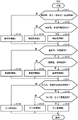
Fig. 7 is a flowchart showing the overall process of the abnormal state monitoring system for a mobile body.
Fig. 8 is a flowchart showing a flag generation process in the moving object.
Fig. 9 is a flowchart showing a priority determination process of a plurality of flags in the management device.
Fig. 10 is a flowchart showing the sensing data selection process of the process S1 in the management apparatus.
Fig. 11 is a flowchart showing the sensed data analysis processing of the processing S2 in the management apparatus.
Fig. 12 is a diagram showing the instruction content based on the flag data and the sensing data in the process S2.
Detailed Description
Hereinafter, embodiments of the present invention will be described in detail with reference to the drawings.
< overview of abnormal State monitoring System of Mobile body 100 >
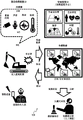
Fig. 1 is a diagram showing an outline of an abnormal state monitoring system 100 for a mobile body according to an embodiment. Fig. 2 is a diagram showing a configuration of an abnormal state monitoring system for a mobile body. The abnormal state monitoring system 100 for a mobile body includes a management device 30 (remote monitoring center) for monitoring abnormal states from a plurality of mobile bodies including a large number of construction machines operating around the world or people working at construction sites thereof, and a mobile body-side device 10 included in the mobile body. When an abnormal state (abnormal state) occurs, the mobile body side apparatus 10 transmits flag data 21 indicating the abnormal state, which will be described later, to the management apparatus 30 of the remote monitoring center. The management device 30 analyzes the flag data 21 and requests the mobile device 10 for necessary sensor data. The mobile-side device 10 transmits the requested sensing data to the management device 30, and the management device 30 transmits instruction information to the mobile-side device 10 based on the flag data and the sensing data.
The abnormal state monitoring system 100 for a mobile body is provided with M sensors at N, and uses P kinds of sensor information. The M, N, and P are sensors provided in the unmanned construction machine shown in fig. 1 and sensors provided in the periphery thereof. In other words, M, N, P refer to the sensors provided in the moving body-side device 10 and the sensors provided around it. Examples of the P-type sensors include an image distance sensor, an acoustic sensor, a vibration sensor, and a temperature sensor. In the case of a person, a smart device held by the person may have a sensor.
The following describes a case of an unmanned construction machine that autonomously travels at a construction site as an example of a mobile body.
The unmanned construction machine performs work according to a planned plan in a normal state, senses changes in the surrounding environment and changes in the self state at any time by using a plurality of sensors, and continuously checks whether or not an abnormal value equal to or larger than a threshold value exists in the output results from the sensors. When an abnormal value equal to or higher than the threshold value is detected as a result of the inspection, the normal state is shifted to the abnormal state.
When the state is shifted to the abnormal state, first, a predetermined emergency measure is executed in accordance with the abnormal value of the sensor. Next, flag data 21 is generated based on the output results from the respective sensors. Further, the management device 30 is notified of the generated flag data 21 via the network NW. After the notification of the flag data 21, the management apparatus 30 waits for receiving an instruction. The instructions from the management device 30 include an instruction in the process S1 and an instruction in the process S2, which will be described later.
Further, the unmanned construction machine which autonomously travels at a construction site has been described as the mobile body, but the same applies to the case of a site operator. In the case of the field worker, the field worker may own (wear on the body) a smart device having various sensors, processing units, and the like, a smart watch, and the like as the mobile body-side device 10.
< abnormal State monitoring System of Mobile body 100 device Structure >
Next, the device configuration will be described with reference to fig. 2.
In step S1, the management device 30 instructs acquisition of necessary sensor data when receiving the flag data 21. In addition, as the processing S2, when receiving the sensing data, the management device 30 analyzes the flag data and the sensing data, and issues an optimal response instruction to the unmanned construction machine at the construction site via the network NW in accordance with the analysis result.
The mobile body side device 10 includes a processing unit 11 for monitoring an abnormal state of the mobile body, a storage unit 20, a communication unit 25 for communicating with an external sensor 27 and a management device 30, and a plurality of internal sensors 26. The processing unit 11 includes a sensor information acquisition unit 12 (sensor information acquisition means) for acquiring sensor information of the plurality of sensors 26 and 27; an abnormality detection unit 13 (abnormality detection means) that determines whether or not the sensor information is abnormal; an abnormality processing unit 14 (control unit) that generates flag data 21 including a flag indicating an abnormality level and status information indicating an abnormal state when the abnormality detection unit determines that the abnormality is occurring, and transmits the flag data 21 to the management device 30; and a flag generating section 15 for generating a flag. The storage unit 20 stores flag data 21, an emergency measure determination table 22, and the like.
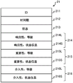
Fig. 3 is a diagram showing an example of the data structure of the flag data 21. The flag data 21 includes an ID211 for identifying the mobile-side device 10 that generates the flag and the notification event, a time stamp 212 indicating the time when the flag data is generated, a state 213 indicating a normal/abnormal state, responsiveness information 214 determined based on an abnormal value from the sensor, importance information 215, and intervention information 216. The responsiveness information 214, the importance information 215, and the intervention information 216 are composed of levels 214L, 215L, and 216L, which are flag levels of the respective information, and state information 214S, 215S, and 216S indicating states of the levels.
The responsiveness information 214 refers to information for determining whether there is an abnormality of a person (field worker) or whether the person is affected. If it is determined that there is a human abnormality or an influence on a human, the responsiveness level is set to "1". Next, it is determined whether the change in the ambient environment and the change in the state of the machine are rapid. If it is determined to be fast, the responsiveness level is set to "2". Otherwise, the responsiveness level is set to "3".
The importance information 215 refers to information for determining whether or not the surrounding environment is greatly influenced. If the influence is judged to be large, the importance level is set to "1". Next, it is determined whether damage to the unmanned construction machine or the equipment used is caused. If it is determined that the breakage has occurred, the responsiveness level is set to "2". Otherwise, the importance level is set to "3".
Referring back to fig. 2, the configuration of the management device 30 will be described.
The management device 30 includes a processing unit 31, a storage unit 40, an input unit 45, a display unit 46, and a communication unit 47. The processing unit 31 includes a priority determination unit 32 that determines priority when receiving a plurality of pieces of flag data, a moving body state monitoring unit 33 that monitors states of the moving body and the surrounding environment, a sensing data selection unit 34 that generates instruction information for sensing data for knowing a state of the moving body, a sensing data analysis unit 35 that generates an instruction for dealing with the moving body, and the like.
The display unit 46 is a display or the like, and displays the execution status, the execution result, and the like of the processing performed by the management device 30. The input unit 45 is a device for inputting instructions to a computer such as a keyboard and a mouse, and inputs instructions such as program activation. The processing unit 31 is a Central Processing Unit (CPU) and executes various programs stored in the storage unit 40 and the like. The communication unit 47 exchanges various data and commands with other devices via the network NW.
The storage unit 40 stores the acquisition data determination table 41 used in the process S1 and to be acquired based on the flag data 21 from the mobile body-side device 10, the instruction determination table 42 used in the process S2 and used for instructing a response to the mobile body-side device 10, the instruction contents 43 based on the flag data 21 and the sensing data, the notification data 44 to the mobile body, and the like.
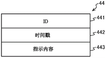
Fig. 4 is a diagram showing an example of the data structure of notification data 44 from management apparatus 30. The notification data 44 includes an ID441 for identifying the mobile-side device 10 that has generated the flag and the notification event, a time stamp 442 as the time at which the notification is generated, instruction contents 443, and the like.
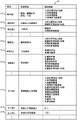
Fig. 5 is a diagram showing an example of the acquired data determination table 41 in the processing S1. The acquired data judgment table 41 includes the level of flag, status information, acquired data, and the like. The level of the flag refers to the levels 214L, 215L, 216L shown in fig. 3, and the state information refers to the state information 214S, 215S, 216S shown in fig. 3.
A specific example will be described for data to be acquired based on the level of the flag and the status information. When the responsiveness level of the row 411 is "1" and information that the posture is slow walking or bad complexion is notified as the state information, the position coordinates and the movement line of the person, the image data of the person, the distance data of the person, and the temperature and humidity around the person are acquired.
When the responsiveness level of the row 412 is "2" and information that the machine and the human are rapidly approaching is notified as the state information, the position coordinates/the movement line of the human and the position coordinates/the movement line of the machine are acquired.
When the responsiveness level of the line 413 is "3" and information that a large gust of rain is notified is used as the state information, the rainfall amount and the surrounding image data are acquired.
When the importance level of the row 414 is "1" and information that the building damage is notified is used as the state information, the position coordinates/movement lines of the person, the position coordinates/movement lines of the machine, the surrounding image data, and the surrounding distance data are acquired.
When the importance level of the line 415 is "2" and information indicating that the machine is damaged is notified as the status information, the sound of the machine and the temperature of the machine are acquired.
When the importance level of the row 416 is "3" and information that maintenance is necessary is notified as the state information, the machine sound, the machine temperature, the continuous operation time, the surrounding image data, the surrounding distance data, and the position coordinates/movement line of the machine are acquired.
When the intervention level of the row 417 is "1" and a skilled person is notified of the information that needs to be judged as the state information, the position coordinates/movement line of the person, the image data of the person, the distance data of the person, the temperature and humidity around the person, the position coordinates/movement line of the machine, the image data around the person, the distance data around the machine, the temperature and humidity around the machine, the rainfall, the sound of the machine, and the temperature of the machine are acquired.
In the case where the intervention level of the row 418 is "2" and information that an artificial intelligence instruction is required is notified as the status information, the same data group as that in the case where the intervention level is "1" is acquired.
In the case where the level of intervention of the row 419 is "3" and information that only emergency measures are performed is notified as the status information, the sensed data does not need to be acquired.
In the example of fig. 5, 3 examples are shown as examples of the level of responsiveness, importance, and intervenience, but the present invention is not limited to these. For example, the rank is "1" and there are a plurality of pieces of status information.
Fig. 6 is a diagram showing an example of the instruction determination table 42 in the process S2. The instruction judgment table 42 includes the level of flag, status information, judgment reference, and the like. The level of the flag refers to the levels 214L, 215L, 216L shown in fig. 3, and the state information refers to the state information 214S, 215S, 216S shown in fig. 3.
A specific example of the determination criterion is described based on the level and state information of the flag and the sensing data. When the responsiveness level of the line 421 is "1" and information that the posture is slow walking or poor complexion is notified as the state information, the walking speed is determined from the position coordinates and the motion curve of the person, the vital sign states such as complexion, pulse, and fatigue are determined from the image data of the person, the posture and fatigue are determined from the distance data of the person, and the comfort level of the working environment is determined from the temperature and humidity around the person.
A decision is that it takes more than 1h to rest if fatigue is above 80%, rescue is needed if posture is curling or falling, it takes more than 1h to rest if a line and walking speed exist and can do a break or a toddler, and it takes 0.5h to rest if air temperature/humidity is 39 degrees/90% for 1 h. Where h is a unit of time.
When the response level of the row 422 is "2" and information that the machine and the human are approaching rapidly is notified as the state information, the closest prediction distance and the closest prediction time are determined from the position coordinates/moving line of the human and the position coordinates/moving line of the machine.
The judgment criterion is to stop the machine if the closest distance is 3 m/the predicted time is 15s, and to alarm people to reduce the moving speed of the machine and change the route if the closest distance is other than the predicted time.
When the responsiveness level of the line 423 is "3" and information such as a large gust of rain is notified as the state information, it is determined whether or not the activity can be continued based on the rainfall amount and the rainfall condition of the surrounding image data. The judgment criterion is that according to the results of the rainfall meter and the image recognition, if 500mm/h lasts for 0.5h, the machine is stopped, and if 500mm/h lasts for 1h, the machine is avoided.
When the importance level of the row 424 is "1" and information that the building damage is notified is used as the state information, the closest distance is determined from the position coordinates/moving lines of the person and the position coordinates/moving lines of the machine, and whether avoidance is necessary or not is determined from the surrounding image data and the surrounding distance data. The criterion is to stop the machine if the closest distance is 3m, and to determine that avoidance is necessary if an unrecognized object or an object that should not be approached is detected as a result of image recognition of surrounding image data and distance data.
When the importance level of row 425 is "2" and information indicating that the component is damaged is notified as the state information, a specific frequency at which failure or deterioration of the component can be predicted is detected by the sound of the machine, and a portion having a high temperature higher than expected is detected by the temperature. The judgment criterion is to stop the machine if the specific frequency is detected for 1 minute as a result of the sound analysis of the machine, and to stop the machine if the portion of 90 degrees or more is detected for 1 minute as a result of the temperature analysis.
When the importance level of the row 426 is "3" and information that maintenance is necessary is notified as the state information, a specific frequency at which failure or deterioration of a component can be predicted is detected from the sound of the machine, a portion that has reached a high temperature more than expected is detected from the temperature of the machine, whether or not maintenance work is necessary is determined from the continuous operation time, and the travel time from the current point to the maintenance location is estimated from the surrounding image data, the surrounding distance data, the position coordinates of the machine, and the line of motion.
As a judgment criterion, if the specific frequency is detected as a result of analyzing the sound of the machine, it is judged that maintenance is required, if the position of 90 degrees or more is detected as a result of analyzing the temperature of the machine, it is judged that maintenance is required, if the continuous operation time is 50h or more, it is judged that maintenance is required, and the time required for movement and the remaining operation time are calculated from the image of the position of the machine and the surrounding and the distance data.
When the intervention level in the row 427 is "1" and it is notified that the skilled person is required to determine such information as the state information, the method of handling when the skilled person has a plurality of abnormalities is determined based on the position coordinates/motion curve of the person, the image data of the person, the distance data of the person, the temperature and humidity around the person, the position coordinates/motion curve of the machine, the image data of the surroundings, the distance data of the surroundings, the temperature and humidity around the surroundings, the rainfall, the sound of the machine, and the temperature of the machine. For example, the determination of priority when a plurality of flags occur simultaneously, or the avoidance instruction when a human/machine avoidance destination/movement destination conflicts.
When the intervention level of the row 428 is "2" and information that an artificial intelligence instruction is required is notified as the status information, a method of handling the artificial intelligence when a single abnormality not included in the emergency handling list has occurred is determined from the database based on the same data group as that in the case where the intervention level is "1". For example, the method is a method for handling a case where an unknown object not present in the list is recognized as a result of image recognition or a case where noise having a frequency not present in the list is detected.
In the case where the intervention level of the line 429 is "3" and information that only emergency measures are executed is notified as the status information, the judgment processing is not necessary.
< Effect of abnormal State monitoring System of Mobile body 100 >
The effect of the abnormal state monitoring system 100 for a mobile body is as follows.
(1) Since the size of the notification data (flag data 21 (see fig. 3)) from the mobile-side apparatus 10 to the management apparatus 30 is small, even if many notifications are simultaneously generated from a plurality of stations, the notification can be made to the management apparatus 30 in real time.
(2) Since the urgency and importance of the management apparatus 30 are determined before the mobile-side apparatus 10 notifies the management apparatus 30, the processing load on the management apparatus 30 side is small. Further, the management device 30 can easily determine the priority, and can deal with many moving objects.
(3) When the mobile body-side device 10 detects the abnormal data, the mobile body first executes emergency measures, and therefore no response delay occurs.
(4) The combination of the sensing by the plurality of sensors enables the on-site situation to be accurately known. For example, in human sensing, by combining the coordinates (position) with the posture, motion, and vital sign information, the state of the field worker (health, fatigue, safety of surrounding machines, and comfort of the work environment) can be known more accurately.
(5) By analyzing the detailed sensing data by the management device 30, it is possible to generate an improvement measure with higher accuracy than the analysis by the moving body side device 10.
< processing of abnormal State monitoring System of Mobile body 100 >
The following describes processing of the abnormal state monitoring system 100 for a mobile object.
Fig. 7 is a flowchart showing the overall processing of the abnormal state monitoring system 100 for a mobile body. The description is made with reference to fig. 2 and 3 as appropriate. The abnormality detection unit 13 of the moving body-side device 10 determines whether the sensor information acquired by the sensor information acquisition unit 12 is abnormal (abnormal) (processing S10), returns to the processing S10 if not (processing S10, no), and performs emergency measures (processing S11) if not (processing S10, yes). The emergency measures are handled based on the emergency measure determination table 22 stored in the storage unit 20. Then, the abnormality processing portion 14 obtains the responsiveness information 214, the importance information 215, and the intervention information 216 shown in fig. 3 via the flag generating portion 15 (processing S13: flag generating processing). Next, the abnormality processing unit 14 notifies the management device 30 of the flag data 21 (see fig. 3) (processing S14).
When the abnormality processing unit 14 of the mobile-body side apparatus 10 receives an instruction from the management apparatus 30 (step S15), it executes an instruction process for collecting the sensing data (step S16). Then, the abnormality processing unit 14 transmits the sensing data to the management device 30 (processing S17).
When receiving the instruction from the management device 30 (step S18), the abnormality processing unit 14 of the mobile body-side device 10 executes the instruction (step S19), and returns to step S10.
On the other hand, when the moving body state monitoring unit 33 of the management device 30 receives the flag data 21 from the moving body side device 10 (step S31), the items of data to be acquired shown in fig. 5 are acquired via the sensor data selecting unit 34 (step S32), and an instruction to acquire sensor data is given to the moving body side device 10 (step S33).
After that, when the moving body state monitoring unit 33 of the management device 30 receives the sensing data from the moving body side device 10 (step S34), the sensing data analysis unit 35 obtains a response instruction from the determination criterion shown in fig. 6 (step S35), and the response instruction is given to the moving body side device 10 (step S36).
Fig. 8 is a flowchart showing the flag generation process (process S13) in the moving body side apparatus 10. The description is made with reference to fig. 2 and 3 as appropriate. The flag generation unit 15 of the moving body side apparatus 10 determines whether or not there is an abnormality of a person (operator) or whether or not there is an influence on the person (processing S131), and if it is determined that there is an abnormality of a person or an influence on the person (processing S131, yes), the level of responsiveness 214L is set to "1", the status information 214S is set (processing S133), and the process proceeds to processing S136. If it is determined that there is no abnormality or influence on the human (no in step S131), the flag generation unit 15 proceeds to step S132.
Next, the flag generation unit 15 determines whether or not the change in the ambient environment and the change in the state of the machine are rapid (the changes are large) (step S132), and if it is determined that the changes are rapid (step S132, yes), sets the level of responsiveness 214L to "2", sets the state information 214S (step S134), and proceeds to step S136. If the change is not fast, otherwise (no in step S132), the flag generation unit 15 sets the level of responsiveness 214L to "3", sets the state information 214S (step S135), and proceeds to step S136.
The flag generation unit 15 determines whether or not the surrounding environment is greatly influenced (whether or not the environment is destroyed) (processing S136), and if it determines that the influence is large (processing S136, yes), the importance level 215L is set to "1", the status information 215S is set (processing S138), and the process proceeds to processing S141. If it is not determined that the influence is large (no in step S136), the flag generation unit 15 proceeds to step S137.
Next, the flag generation unit 15 determines whether or not the construction machine or the equipment in use is damaged (step S137), and if it is determined that the damage is caused (yes in step S137), sets the importance level 215L to "2", sets the status information 215S (step S139), and proceeds to step S141. Otherwise (no in step S137), the importance level 215L is set to "3", the status information 215S is set (step S140), and the process proceeds to step S141.
Further, the flag generation unit 15 may determine whether or not only the emergency process is to be performed (process S141), and if it is determined that only the emergency process is to be performed (process S141, yes), the intervention level 216L is set to "3", the status information 216S is set (process S143), and the flag generation process is ended (process S13). If only the emergency processing is not possible (processing S141, no), the flag generation unit 15 proceeds to processing S142.
The flag generation unit 15 determines whether or not the handling by artificial intelligence is necessary (processing S142), and if it is determined that the handling by artificial intelligence is necessary (processing S142, yes), sets the intervention level 216L to "2", sets the status information 216S (processing S144), and ends the flag generation processing (processing S13). If the artificial intelligence is not necessary (no in the process S142), the flag generation unit 15 sets the intervention level 216L to "1", sets the status information 216S (process S145), and ends the flag generation process (process S13).
Fig. 9 is a flowchart showing the priority determination processing (processing S32) of the plurality of flags in the management server. The description is made with reference to fig. 2 and 3 as appropriate. The priority determination process further specifically shows the processes S31 to S36 of the moving object state monitoring unit 33 shown in fig. 7. The processes S31, S34 of fig. 7 correspond to the process S328 of fig. 9, and the processes S32, S35 of fig. 7 correspond to the process S327 of fig. 9. In addition, the processes S33, S36 of fig. 7 correspond to the process S327 of fig. 9.
The priority determination unit 32 of the management device 30 determines whether or not a reception queue transmitted from a mobile object in each area remains (step S321), and if a reception queue exists (step S321, yes), generates a response time limit based on the time stamp 212 of the flag data 21 and the level 214L of responsiveness (step S322), and returns to step S321. If no reception queue remains (no in step S321), the priority determination unit 32 proceeds to step S323.
The priority determination unit 32 sorts the receive queues in order of response time limit from early to late (processing S323), determines whether or not an unprocessed receive queue remains (processing S324), and if there is a remaining receive queue (processing S324, yes), proceeds to processing S325, and if there is no receive queue (processing S324, no), proceeds to processing S328.
Then, the priority determination unit 32 takes out the head of the reception queue (process S325), analyzes the head in process S1 or process S2 (process S326), transmits the instruction information to the mobile object (process S327), and returns to process S324.
In the process S328, the priority determination unit 32 determines whether or not the flag data 21 is received from the mobile device side apparatus 10, and if the flag data 21 is not received (no in the process S328), the process returns to the process S328, and if the flag data 21 is received (yes in the process S328), the process returns to the process S321.
Fig. 10 is a flowchart showing the sensing data selection processing (processing S34) of the processing S1 in the management apparatus 30. Reference is made to fig. 2 and 3 as appropriate. The sensed data selecting unit 34 selects sensed data necessary for analysis based on the acquired data determination table 41.
The sensing data selection unit 34 determines whether or not the responsiveness level is "1" (processing S341), and if the responsiveness level is "1" and information that the posture is slow walking or poor complexion is notified as the state information (processing S341 yes), selects the position coordinates and the movement line of the person, the image data of the person, the distance data of the person, and the atmospheric temperature and humidity around the person as the acquisition data (processing S343). Proceed to process S346. If the responsiveness level is not "1" (no in step S341), the sensor data selector 34 proceeds to step S342.
The sensing data selecting unit 34 determines whether or not the responsiveness level is "2" (step S342), and if the responsiveness level is "2" and information that the machine and the human are approaching rapidly is notified as the status information (yes in step S342), selects the position coordinates/movement lines of the human and the position coordinates/movement lines of the machine as the acquired data (step S344), and proceeds to step S346. If the responsiveness level is not "2" (no in step S342), the sensed data selecting unit 34 proceeds to step S345.
In step S345, when the responsiveness level is "3" and information that a heavy rain is notified is given as the state information, the sensor data selector 34 selects the amount of rainfall and the surrounding image data as the acquisition data, and proceeds to step S346.
In step S346, the sensing data selecting unit 34 determines whether the importance level is "1" or not, and if the importance level is "1" and information that the building damage is notified is used as the status information (yes in step S346), selects the position coordinates/movement line of the person, the position coordinates/movement line of the machine, the surrounding image data, and the surrounding distance data as the acquisition data (step S348), and proceeds to step S34B. If the importance level is not "1" (no in step S346), the sensed data selecting unit 34 proceeds to step S347.
When the importance level is "2" and information indicating that the sensor data selecting unit has notified the damage itself is used as the status information (yes in step S347), the sensor data selecting unit selects the machine sound and the machine temperature as the acquired data (step S349), and the process proceeds to step S34B. If the importance level is not "2" (no in step S347), the sensed data selecting unit 34 proceeds to step S34A.
In step S34A, when the importance level is "3" and information indicating that maintenance is necessary is notified as the state information, the sensor data selector 34 selects the machine sound, the machine temperature, the continuous operation time, the surrounding image data, the surrounding distance data, and the machine position coordinates/motion line as the acquisition data, and proceeds to step S34B.
In the process S34B, the sensing data selecting unit 34 determines whether the intervention level is "1" or "2", and if information that a skilled person is required to determine and an artificial intelligence instruction is required is notified as the status information (yes in the process S34B), selects the position coordinates/movement line of the person, the image data of the person, the distance data of the person, the temperature and humidity around the person, the position coordinates/movement line of the machine, the image data around the person, the distance data around the person, the temperature and humidity around the machine, the amount of rainfall, the sound of the machine, and the temperature of the machine as the acquisition data (process S34C), and ends the sensing data selecting process of the process S1 (process S34). If the intervention level is not "1" or "2" (no in step S34B), the sensing data selection process of step S1 is ended (step S34).
Fig. 11 is a flowchart showing the sensing data analysis processing (processing S35) of the processing S2 in the management apparatus 30. Reference is made to fig. 2 and 3 as appropriate. The sensing data selection unit 34 selects a response instruction for the moving object based on the flag data 21, the sensing data, and the instruction determination table 42.
The sensory data analysis unit 35 determines whether or not the moving object is a human (process S351), and if the moving object is a human, analyzes the coordinates of the human from the acquired sensory data (process S353), analyzes the posture movement (process S354), analyzes the vital sign (process S355), analyzes the environment around the human (process S356), generates instruction information (process S357), and ends the sensory data analysis process of the process S2 (process S35). If the moving object is not a human (no in step S351), the sensor data analyzer 35 proceeds to step S352.
The vital sign is a vital sign (visual signs). Is the most basic information about the patient's life that is also translated into vital signs (sign) of life (total). Specifically, the 4 items of pulse or heart rate/respiration (number)/blood pressure/body temperature are mostly known/expressed from the numerical information.
In the processing S353 to S346, when the responsiveness level is "1" and information that the posture is slow walking or poor complexion is notified as the state information, the sensing data analysis unit 35 determines the walking speed from the position coordinates and the motion curve of the person, determines the vital sign states such as complexion, pulse, and fatigue from the image data of the person, determines the posture and the fatigue from the distance data of the person, and determines the comfort level of the working environment from the temperature and humidity around the person.
In the process S357, it is determined that it is necessary to take a rest of 1h or more if the fatigue is 80% or more, it is necessary to rescue if the posture is curling or falling, it is necessary to take a rest of 1h or more if there is a slip or a walking speed, and it is necessary to take a rest of 0.5h if the air temperature/humidity continues to 1h at 39 degrees/90%.
In the processing S353 to S346, when the responsiveness level is "2" and information that the machine and the human are rapidly approaching is notified as the state information, the sensing data analysis unit 35 determines the closest predicted distance and the closest predicted time from the position coordinates/moving lines of the human and the position coordinates/moving lines of the machine.
In step S357, the determination criterion is to stop the machine if the closest distance is 3 m/the predicted time is 15S, and to alert a person to reduce the moving speed of the machine and change the route if the closest distance is not 3 m/the predicted time is other than 15S.
In step S357, when the responsiveness level is "3" and information such as a large gust of rain is notified as the state information, the sensed data analyzer 35 determines whether or not the activity can be continued based on the rainfall amount and the rainfall condition of the surrounding image data. The judgment criterion is that according to the results of the rainfall meter and the image recognition, if 500mm/h lasts for 0.5h, the machine is stopped, and if 500mm/h lasts for 1h, the machine is avoided.
The sensor data analyzer 35 determines whether or not the mobile object is an unmanned construction machine (step S352), and if the mobile object is an unmanned construction machine (step S352, yes), analyzes the machine coordinates from the acquired sensor data (step S360), analyzes the surrounding environment (step S361), analyzes the machine state (step S362), generates instruction information (step S363), and ends the sensor data analysis process of step S2 (step S35). When the mobile object is not an unmanned construction machine (no in step S352), the sensor data analyzer 35 proceeds to step S365.
In the processing S360 to S362, when the importance level is "1" and information that the building damage is notified is used as the state information, the sensing data analysis unit 35 determines the closest distance from the position coordinates/movement lines of the person and the position coordinates/movement lines of the machine, and determines whether or not avoidance is necessary from the surrounding image data and the surrounding distance data.
In step S363, the machine is stopped if the closest distance is 3m, and if the result of image recognition of the surrounding image data and distance data is that an unidentified object or an object that should not be approached is detected, it is determined that avoidance is necessary.
In the processing S360 to S362, when the importance level is "2" and information indicating that the component is damaged is notified as the state information, the sensing data analysis unit 35 detects a specific frequency at which failure or deterioration of the component can be predicted from the sound of the machine, and detects a portion having a high temperature higher than expected from the temperature.
In step S363, the judgment criterion is that the machine is stopped if the specific frequency is detected for 1 minute as a result of analyzing the sound of the machine, and the machine is stopped if the portion of 90 degrees or more is detected for 1 minute as a result of analyzing the temperature.
In the processing S360 to S362, when the importance level is "3" and information that maintenance is necessary is notified as the state information, the sensing data analysis unit 35 detects a specific frequency with which failure or deterioration of the component can be predicted from the sound of the machine, detects a portion having a high temperature higher than expected from the temperature, determines whether maintenance work is necessary from the continuous operation time, and estimates the moving time from the current point to the maintenance location from the surrounding image data, the surrounding distance data, and the position coordinates and the movement line of the machine.
In step S363, the judgment criterion is that maintenance is required if the specific frequency is detected as a result of the analysis of the machine sound, maintenance is required if a portion of 90 degrees or more is detected as a result of the analysis of the temperature, maintenance is required if the continuous operation time is 50 hours or more, and the time required for movement and the remaining operation time are calculated from the image of the position of the machine itself and the surrounding image and the distance data.
In the process S365, the sensor data analyzer 35 analyzes the surrounding environment to generate instruction information (process S366), and ends the sensor data analysis process in the process S2 (process S35).
In the process S365, when the intervention level is "1" and the skilled person is notified of the information that requires judgment as the state information, the sensing data analysis unit 35 judges the method to be handled when the skilled person has a plurality of abnormalities based on the position coordinates/movement line of the person, the image data of the person, the distance data of the person, the temperature and humidity around the person, the position coordinates/movement line of the machine, the image data of the surroundings, the distance data of the surroundings, the temperature and humidity around the person, the rainfall, the sound of the machine, and the temperature of the machine. For example, the determination of priority when a plurality of flags occur simultaneously, or the avoidance instruction when a human/machine avoidance destination/movement destination conflicts.
In the process S365, when the intervention level is "2" and information that the instruction of artificial intelligence is required is notified as the status information, the sensed data analysis unit 35 determines, from the database, a method of dealing with the artificial intelligence when the individual abnormality not included in the emergency handling list has occurred based on the same data group as that in the case where the intervention level is "1". For example, the method is a method for handling a case where an unknown object not present in the list is recognized as a result of image recognition or a case where noise having a frequency not present in the list is detected.
In the process S365, when the intervention level is "3" and information indicating that only emergency measures are performed is notified as the status information, the sensing data analysis unit 35 does not need the determination process.
Fig. 12 is a diagram showing the instruction content based on the flag data and the sensed data in the process S2. In line 431, in the case where the responsiveness level is "1" and information that the posture is walking slowly and poor in complexion is notified as the state information, it is determined from the moving line and the distance data that the walking speed is 2km/h, the person is walking in a shape-modifying pattern, and it is determined from the complexion that the vital sign state is 90% in fatigue, and since the temperature and humidity are 37 degrees and 90%, it is determined that the comfort level of the work environment is poor, thereby indicating that the rest of 1h or more is required.
In line 432, when the responsiveness level is "2" and information that the machine and the human are approaching rapidly is notified as the state information, it is determined that the moving speed of the human is 4km/h, the moving speed of the machine is 40km/h, the closest predicted distance between the human and the machine is 1m, and the closest predicted time is 20 seconds later, and therefore, a decrease in the machine speed is instructed.
In row 433, when the responsiveness level is "3" and information such as a large gust of rain is notified as the state information, since the rainfall amount is 100m for 5 hours, it is determined that the rainfall is confirmed from the rainfall condition of the surrounding image data, and it is determined that the movement cannot be continued, and therefore, it is instructed to stop the machine.
In row 434, when the importance level is "1" and information that the building damage is notified is used as the state information, it is determined that there is another machine in the periphery but no human from the closest distance 5m between the human and the machine and the analysis result of the image and the distance data, and the instruction is given to avoid the machine.
In row 435, when the importance level is "2" and information that self-destruction is notified is used as the status information, the machine is instructed to stop because it detects that the specific frequency 90Hz reaches 1 minute or more from the machine sound and detects that the position reaches 90 degrees or more for 1 minute or more from the temperature.
In line 436, when the importance level is "3" and information that maintenance is necessary is notified as the status information, the specific frequency (90Hz) is detected, a portion having a temperature of 90 degrees or more is detected, the continuous operation time is 50h or more, and it is determined from the image of the position of the user, the surrounding image, and the distance data that the time required for movement is 2h and the remaining operation time is 6h, and therefore, the operation is instructed to be ended 4 hours at maximum, and the operation is shifted to the maintenance operation.
In line 437, when the intervention level is "1" and information that a skilled person is required to determine is notified as the state information, the skilled person recognizes that a plurality of abnormalities such as 2 machines approaching each other are occurring based on the position coordinates/moving line of the person, the image data of the person, the distance data of the person, the temperature and humidity around the person, the position coordinates/moving line of the machine, the image data of the surroundings, the distance data of the surroundings, the temperature and humidity around the person, the rainfall, the sound of the machine, and the temperature of the machine, and recognizes that a person is present near the avoidance destination, and instructs 3 machines to stop and issue an alarm to the person.
In the line 438, when the intervention level is "2" and information that an instruction of artificial intelligence is required is notified as the state information, the artificial intelligence determines that the unknown object is an abnormally intruding vehicle based on the same data set as that in the case of the intervention level being "1" and based on the analysis result from the database of image data, and instructs the machine to stop and to issue an alarm to a person present in the periphery and the abnormally intruding vehicle.
In the row 439, when the intervention level is "3" and information indicating that only emergency measures are performed is notified as the status information, no instruction is given.
According to the above embodiment, the following features are provided.
The abnormal state monitoring system 100 of a mobile body includes a management device 30 that transmits instruction information for the mobile body based on abnormal information of an abnormal state transmitted from a plurality of mobile bodies, and a mobile body-side device 10 included in the mobile body, and the mobile body-side device 10 includes: a communication unit (e.g., communication unit 25) capable of communicating with management device 30; a sensor information acquisition unit (for example, a sensor information acquisition unit 12) capable of acquiring sensor information of a plurality of sensors; abnormality detection means (e.g., abnormality detection section 13) for determining whether or not the sensor information is abnormal; and a control unit (for example, the abnormality processing unit 14 and the flag generating unit 15) that generates flag data 21 including a flag indicating an abnormality level and status information indicating an abnormal state when the abnormality detecting unit determines that the abnormality is present, and transmits the flag data to the management device. This makes it possible to reduce the size of the notification data (flag data 21 (see fig. 3)) from the mobile-side apparatus 10 to the management apparatus 30, and thus to provide an effect of notifying the management apparatus 30 in real time even when many notifications are simultaneously generated from a plurality of stations.
The management device 30 has a storage unit 40 that stores an acquisition data determination table 41 that associates the abnormality level and the state information with the acquisition data, and can transmit an instruction to acquire necessary sensing data to the mobile body-side device 10 in accordance with the abnormality level of the flag data 21 when the flag data 21 is received from the mobile body-side device 10.
Further, the management device 30 stores a handling method determination table for determining a handling method based on the abnormality level, the state information, and the sensing data in the storage unit 40, and when the sensing data is received from the mobile body-side device 10, can transmit instruction information as a handling method for the mobile body to the mobile body-side device 10 based on the handling method determination table (for example, the instruction determination table 42).
The flag data 21 includes responsiveness information for determining whether there is an abnormality of a person or whether there is an influence on the person, importance information for determining whether there is a large influence on the surrounding environment, and intervention information for determining whether or not expert intervention is required in remote instruction. Thus, since the urgency and importance of the management apparatus 30 are determined before the mobile-side apparatus 10 notifies the management apparatus 30, the processing load on the management apparatus 30 side is small. Further, management device 30 has an effect of making it easy to determine the priority and enabling a response to a large number of moving objects.
In the present embodiment, the moving body is described with respect to the unmanned construction machine and the site operator at the construction site, but the moving body is not limited thereto. For example, there are an automated guided vehicle for carrying goods in a warehouse and an automated guided vehicle on a road.
Description of the reference numerals
10 moving body side device
11 treatment section
12 sensor information acquisition unit (sensor information acquisition unit)
13 abnormality detection unit (abnormality detection means)
14 Exception handling section (control unit)
15 sign generation unit (control unit)
20 storage part
21 flag data
25 communication part (communication unit)
26. 27 sensor
30 management device
31 treatment section
32 priority degree determination unit
33 moving body state monitoring unit
34 sensing data selecting part
35 a sensing data analysis section
40 storage part
41 acquisition data judgment table
42 instruction judgment table (coping method judgment table)
43 indicates the contents
44 notification data
100 abnormal state monitoring system for mobile body
214 responsiveness information
215 importance information
216 interventional information
214L, 215L, 216L level
214S, 215S, 216S status information.
Claims (5)
1. An abnormal state monitoring system for a mobile body, comprising:
a management device for transmitting instruction information to a plurality of mobile bodies based on abnormal information of an abnormal state transmitted from the mobile bodies; and
a moving body side device provided in the moving body,
the moving body side device includes:
a communication unit capable of communicating with the management apparatus;
a sensor information acquisition unit capable of acquiring sensor information of a plurality of sensors;
an abnormality detection unit for judging whether the sensor information is abnormal; and
and a control unit that generates flag data including a flag indicating an abnormality level and status information indicating an abnormal state when the abnormality detection unit determines that the abnormality occurs, and transmits the flag data to the management device.
2. The abnormal state monitoring system of a movable body according to claim 1, characterized in that:
the management device is used for managing the data transmission,
a storage unit for storing a data acquisition judgment table in which the abnormality level, the state information, and the acquired data are associated,
when the flag data is received from the mobile body-side device, an instruction to acquire necessary sensing data is transmitted to the mobile body-side device in accordance with the abnormality level of the flag data.
3. The abnormal state monitoring system of a movable body according to claim 2, characterized in that:
the management device is used for managing the operation of the mobile terminal,
a coping method determination table for determining a coping method based on the abnormality level, the state information, and the sensing data is stored in the storage unit,
when the sensor data is received from the mobile body-side device, instruction information as a method of dealing with the mobile body is transmitted to the mobile body-side device based on the method-of-dealing determination table.
4. The abnormal state monitoring system of a movable body according to claim 1, characterized in that:
the flag data includes responsiveness information for determining whether there is an abnormality of a person or whether there is an influence on the person, importance information for determining whether there is a large influence on the surrounding environment, and intervention information for determining whether there is a need for an intervention of an expert in the remote instruction.
5. The abnormal state monitoring system of a movable body according to claim 1, characterized in that:
the mobile body includes an unmanned construction machine and a site operator at a construction site.
Applications Claiming Priority (3)
| Application Number | Priority Date | Filing Date | Title |
|---|---|---|---|
| JP2020-025142 | 2020-02-18 | ||
| JP2020025142A JP2021131599A (en) | 2020-02-18 | 2020-02-18 | Abnormal state monitoring system for mobile objects |
| PCT/JP2020/038633 WO2021166320A1 (en) | 2020-02-18 | 2020-10-13 | Moving body abnormal state monitoring system |
Publications (1)
| Publication Number | Publication Date |
|---|---|
| CN115023676A true CN115023676A (en) | 2022-09-06 |
Family
ID=77390630
Family Applications (1)
| Application Number | Title | Priority Date | Filing Date |
|---|---|---|---|
| CN202080094773.4A Pending CN115023676A (en) | 2020-02-18 | 2020-10-13 | Abnormal state monitoring system for moving body |
Country Status (4)
| Country | Link |
|---|---|
| US (1) | US20230107387A1 (en) |
| JP (1) | JP2021131599A (en) |
| CN (1) | CN115023676A (en) |
| WO (1) | WO2021166320A1 (en) |
Family Cites Families (10)
| Publication number | Priority date | Publication date | Assignee | Title |
|---|---|---|---|---|
| US3382305A (en) * | 1954-10-29 | 1968-05-07 | Du Pont | Process for preparing oriented microfibers |
| CA2381674A1 (en) * | 2002-04-12 | 2003-10-12 | Layne Daniel Tucker | Method and apparatus for determining positioning of mobile machines relative to utility lines |
| DE112012004840B4 (en) * | 2011-11-21 | 2022-08-04 | Hitachi Construction Machinery Co., Ltd. | Operating data acquisition device for construction machines |
| JP6162997B2 (en) * | 2013-04-02 | 2017-07-12 | 株式会社日立製作所 | Plant equipment management system and control method of plant equipment management system |
| US20160051153A1 (en) * | 2014-08-25 | 2016-02-25 | Rayan Nabil M. Mously | Radio frequency identification (rfid) enabled wireless heart rate monitoring system |
| JP6234359B2 (en) * | 2014-12-15 | 2017-11-22 | 日立建機株式会社 | Oil quality diagnosis system for work machines |
| JP6725253B2 (en) * | 2016-01-29 | 2020-07-15 | 日立Geニュークリア・エナジー株式会社 | Plant monitoring device and program |
| US20190224841A1 (en) * | 2018-01-24 | 2019-07-25 | Seismic Holdings, Inc. | Exosuit systems and methods for monitoring working safety and performance |
| JP7063022B2 (en) * | 2018-03-14 | 2022-05-09 | オムロン株式会社 | Anomaly detection system, support device and model generation method |
| US11650595B2 (en) * | 2019-07-30 | 2023-05-16 | Caterpillar Inc. | Worksite plan execution |
-
2020
- 2020-02-18 JP JP2020025142A patent/JP2021131599A/en not_active Ceased
- 2020-10-13 WO PCT/JP2020/038633 patent/WO2021166320A1/en active Application Filing
- 2020-10-13 CN CN202080094773.4A patent/CN115023676A/en active Pending
- 2020-10-13 US US17/798,674 patent/US20230107387A1/en active Pending
Also Published As
| Publication number | Publication date |
|---|---|
| US20230107387A1 (en) | 2023-04-06 |
| WO2021166320A1 (en) | 2021-08-26 |
| JP2021131599A (en) | 2021-09-09 |
Similar Documents
| Publication | Publication Date | Title |
|---|---|---|
| Sanhudo et al. | Activity classification using accelerometers and machine learning for complex construction worker activities | |
| CN111650919B (en) | Multi-dimensional monitoring escalator fault prediction and health management method and system | |
| EP2345942A2 (en) | Plant analysis system | |
| GB2601937A (en) | Method and system for managing a crane and/or construction site | |
| CN113724105A (en) | Building construction site monitoring system and monitoring method thereof | |
| CN109160419B (en) | Anti-collision central processing device for building construction tower crane group | |
| KR20160060435A (en) | Smart safety helmet and method, safety management system and method using thereof | |
| CN107902515A (en) | A kind of traction and forcibly driving elevator real time on-line safety monitoring system and its implementation | |
| US20230195086A1 (en) | Abnormal state monitoring system and abnormal state monitoring method | |
| CN114859839B (en) | Coal production safety monitoring system and method | |
| CN115023676A (en) | Abnormal state monitoring system for moving body | |
| CN207698952U (en) | A kind of traction and forcibly driving elevator real time on-line safety monitoring system | |
| JP2009163537A (en) | Fall determination system, fall determination method, and fall determination program | |
| KR20210062963A (en) | Construction safety monitoring system and a method for controlling the same | |
| KR102305487B1 (en) | System and method for providing harmful environment notification service through collection and analysis of working environment information and biometrics information of workers | |
| CN116050930A (en) | Monitoring disc system, monitoring disc method, storage medium and electronic equipment | |
| CN113448293B (en) | Plant monitoring system | |
| US11571142B2 (en) | Fall detection and identification by using data from human condition safety tags | |
| KR20240033381A (en) | Ai server providing a worker safety control solution and operation method of ai system including the same | |
| KR101670412B1 (en) | Mornitoring system for near miss in workplace and Mornitoring method using thereof | |
| CN113885418B (en) | Remote monitoring system and method for environmental parameters of multiple machine cabins | |
| CN117875911B (en) | Coal mine safety production management system for disaster comprehensive control | |
| KR102519988B1 (en) | Monitoring system for accident worker using camera | |
| KR20220159801A (en) | Construction safety monitoring system and a method for controlling the same | |
| CN116664100A (en) | BIM+AI-based intelligent operation and maintenance management system |
Legal Events
| Date | Code | Title | Description |
|---|---|---|---|
| PB01 | Publication | ||
| PB01 | Publication | ||
| SE01 | Entry into force of request for substantive examination | ||
| SE01 | Entry into force of request for substantive examination |