CN115013912A - Control method and device of fresh air system, storage medium and fresh air system - Google Patents
Control method and device of fresh air system, storage medium and fresh air system Download PDFInfo
- Publication number
- CN115013912A CN115013912A CN202210758582.4A CN202210758582A CN115013912A CN 115013912 A CN115013912 A CN 115013912A CN 202210758582 A CN202210758582 A CN 202210758582A CN 115013912 A CN115013912 A CN 115013912A
- Authority
- CN
- China
- Prior art keywords
- fresh air
- air system
- started
- heating
- unit
- Prior art date
- Legal status (The legal status is an assumption and is not a legal conclusion. Google has not performed a legal analysis and makes no representation as to the accuracy of the status listed.)
- Pending
Links
- 238000000034 method Methods 0.000 title claims abstract description 48
- 238000010438 heat treatment Methods 0.000 claims abstract description 115
- 238000005057 refrigeration Methods 0.000 claims abstract description 47
- 230000006870 function Effects 0.000 claims description 71
- 238000001816 cooling Methods 0.000 claims description 32
- 244000241872 Lycium chinense Species 0.000 claims description 18
- 235000015468 Lycium chinense Nutrition 0.000 claims description 18
- 238000004590 computer program Methods 0.000 claims description 7
- 238000009423 ventilation Methods 0.000 claims 3
- 230000033228 biological regulation Effects 0.000 abstract description 4
- 230000001276 controlling effect Effects 0.000 description 33
- 239000003507 refrigerant Substances 0.000 description 20
- 230000008859 change Effects 0.000 description 15
- 238000010586 diagram Methods 0.000 description 8
- 235000013399 edible fruits Nutrition 0.000 description 8
- 230000008569 process Effects 0.000 description 6
- 238000009434 installation Methods 0.000 description 5
- 238000012546 transfer Methods 0.000 description 5
- 238000009792 diffusion process Methods 0.000 description 4
- 238000002474 experimental method Methods 0.000 description 4
- 230000017525 heat dissipation Effects 0.000 description 4
- 230000008878 coupling Effects 0.000 description 3
- 238000010168 coupling process Methods 0.000 description 3
- 238000005859 coupling reaction Methods 0.000 description 3
- 238000009413 insulation Methods 0.000 description 3
- 230000004048 modification Effects 0.000 description 3
- 238000012986 modification Methods 0.000 description 3
- 238000004321 preservation Methods 0.000 description 3
- 238000007789 sealing Methods 0.000 description 3
- 238000012360 testing method Methods 0.000 description 3
- 239000002699 waste material Substances 0.000 description 3
- 238000004891 communication Methods 0.000 description 2
- 238000005265 energy consumption Methods 0.000 description 2
- 238000005516 engineering process Methods 0.000 description 2
- 238000001514 detection method Methods 0.000 description 1
- 230000007613 environmental effect Effects 0.000 description 1
- 239000011521 glass Substances 0.000 description 1
- 230000006872 improvement Effects 0.000 description 1
- 230000003287 optical effect Effects 0.000 description 1
- 230000002093 peripheral effect Effects 0.000 description 1
- 238000012545 processing Methods 0.000 description 1
- 238000005086 pumping Methods 0.000 description 1
- 230000001105 regulatory effect Effects 0.000 description 1
- 238000011160 research Methods 0.000 description 1
- 238000004088 simulation Methods 0.000 description 1
- 230000008719 thickening Effects 0.000 description 1
Images


Classifications
-
- F—MECHANICAL ENGINEERING; LIGHTING; HEATING; WEAPONS; BLASTING
- F24—HEATING; RANGES; VENTILATING
- F24F—AIR-CONDITIONING; AIR-HUMIDIFICATION; VENTILATION; USE OF AIR CURRENTS FOR SCREENING
- F24F7/00—Ventilation
- F24F7/04—Ventilation with ducting systems, e.g. by double walls; with natural circulation
- F24F7/06—Ventilation with ducting systems, e.g. by double walls; with natural circulation with forced air circulation, e.g. by fan positioning of a ventilator in or against a conduit
-
- F—MECHANICAL ENGINEERING; LIGHTING; HEATING; WEAPONS; BLASTING
- F24—HEATING; RANGES; VENTILATING
- F24F—AIR-CONDITIONING; AIR-HUMIDIFICATION; VENTILATION; USE OF AIR CURRENTS FOR SCREENING
- F24F11/00—Control or safety arrangements
- F24F11/30—Control or safety arrangements for purposes related to the operation of the system, e.g. for safety or monitoring
- F24F11/46—Improving electric energy efficiency or saving
-
- F—MECHANICAL ENGINEERING; LIGHTING; HEATING; WEAPONS; BLASTING
- F24—HEATING; RANGES; VENTILATING
- F24F—AIR-CONDITIONING; AIR-HUMIDIFICATION; VENTILATION; USE OF AIR CURRENTS FOR SCREENING
- F24F11/00—Control or safety arrangements
- F24F11/62—Control or safety arrangements characterised by the type of control or by internal processing, e.g. using fuzzy logic, adaptive control or estimation of values
- F24F11/63—Electronic processing
- F24F11/64—Electronic processing using pre-stored data
-
- F—MECHANICAL ENGINEERING; LIGHTING; HEATING; WEAPONS; BLASTING
- F24—HEATING; RANGES; VENTILATING
- F24F—AIR-CONDITIONING; AIR-HUMIDIFICATION; VENTILATION; USE OF AIR CURRENTS FOR SCREENING
- F24F11/00—Control or safety arrangements
- F24F11/62—Control or safety arrangements characterised by the type of control or by internal processing, e.g. using fuzzy logic, adaptive control or estimation of values
- F24F11/63—Electronic processing
- F24F11/65—Electronic processing for selecting an operating mode
- F24F11/67—Switching between heating and cooling modes
-
- F—MECHANICAL ENGINEERING; LIGHTING; HEATING; WEAPONS; BLASTING
- F24—HEATING; RANGES; VENTILATING
- F24F—AIR-CONDITIONING; AIR-HUMIDIFICATION; VENTILATION; USE OF AIR CURRENTS FOR SCREENING
- F24F11/00—Control or safety arrangements
- F24F11/70—Control systems characterised by their outputs; Constructional details thereof
- F24F11/72—Control systems characterised by their outputs; Constructional details thereof for controlling the supply of treated air, e.g. its pressure
- F24F11/74—Control systems characterised by their outputs; Constructional details thereof for controlling the supply of treated air, e.g. its pressure for controlling air flow rate or air velocity
- F24F11/77—Control systems characterised by their outputs; Constructional details thereof for controlling the supply of treated air, e.g. its pressure for controlling air flow rate or air velocity by controlling the speed of ventilators
-
- F—MECHANICAL ENGINEERING; LIGHTING; HEATING; WEAPONS; BLASTING
- F24—HEATING; RANGES; VENTILATING
- F24F—AIR-CONDITIONING; AIR-HUMIDIFICATION; VENTILATION; USE OF AIR CURRENTS FOR SCREENING
- F24F11/00—Control or safety arrangements
- F24F11/70—Control systems characterised by their outputs; Constructional details thereof
- F24F11/80—Control systems characterised by their outputs; Constructional details thereof for controlling the temperature of the supplied air
- F24F11/83—Control systems characterised by their outputs; Constructional details thereof for controlling the temperature of the supplied air by controlling the supply of heat-exchange fluids to heat-exchangers
- F24F11/84—Control systems characterised by their outputs; Constructional details thereof for controlling the temperature of the supplied air by controlling the supply of heat-exchange fluids to heat-exchangers using valves
-
- F—MECHANICAL ENGINEERING; LIGHTING; HEATING; WEAPONS; BLASTING
- F24—HEATING; RANGES; VENTILATING
- F24F—AIR-CONDITIONING; AIR-HUMIDIFICATION; VENTILATION; USE OF AIR CURRENTS FOR SCREENING
- F24F11/00—Control or safety arrangements
- F24F11/70—Control systems characterised by their outputs; Constructional details thereof
- F24F11/80—Control systems characterised by their outputs; Constructional details thereof for controlling the temperature of the supplied air
- F24F11/87—Control systems characterised by their outputs; Constructional details thereof for controlling the temperature of the supplied air by controlling absorption or discharge of heat in outdoor units
-
- F—MECHANICAL ENGINEERING; LIGHTING; HEATING; WEAPONS; BLASTING
- F24—HEATING; RANGES; VENTILATING
- F24F—AIR-CONDITIONING; AIR-HUMIDIFICATION; VENTILATION; USE OF AIR CURRENTS FOR SCREENING
- F24F2110/00—Control inputs relating to air properties
- F24F2110/10—Temperature
-
- Y—GENERAL TAGGING OF NEW TECHNOLOGICAL DEVELOPMENTS; GENERAL TAGGING OF CROSS-SECTIONAL TECHNOLOGIES SPANNING OVER SEVERAL SECTIONS OF THE IPC; TECHNICAL SUBJECTS COVERED BY FORMER USPC CROSS-REFERENCE ART COLLECTIONS [XRACs] AND DIGESTS
- Y02—TECHNOLOGIES OR APPLICATIONS FOR MITIGATION OR ADAPTATION AGAINST CLIMATE CHANGE
- Y02B—CLIMATE CHANGE MITIGATION TECHNOLOGIES RELATED TO BUILDINGS, e.g. HOUSING, HOUSE APPLIANCES OR RELATED END-USER APPLICATIONS
- Y02B30/00—Energy efficient heating, ventilation or air conditioning [HVAC]
- Y02B30/70—Efficient control or regulation technologies, e.g. for control of refrigerant flow, motor or heating
Abstract
The invention provides a control method and a control device of a fresh air system, a storage medium and the fresh air system, wherein the control method comprises the following steps: after the fresh air system is started, determining whether the refrigerating or heating function of the fresh air system needs to be started; if the refrigeration or heating function of the fresh air system needs to be started, controlling the heat exchange equipment of an outdoor unit of the fresh air system to be started, controlling a fan of the fresh air system to be started, and controlling the switch of a corresponding air valve according to a user control command; and if the refrigeration or heating function of the fresh air system is determined not to be started, directly controlling the fan of the fresh air system to be started, and controlling the switch of the corresponding air valve according to a user control command. The scheme provided by the invention can reduce the power consumption of the system and improve the temperature and humidity regulation rate.
Description
Technical Field
The invention relates to the field of control, in particular to a control method and device of a fresh air system, a storage medium and the fresh air system.
Background
The fresh air system is an air conduction device with the concept of 'fresh air change', and the purpose that fresh air can be breathed without opening doors and windows is achieved by pumping outdoor fresh air into a room. Most of fresh air systems on the market at present have refrigeration and heating functions. The passive house, namely a passive low-energy-consumption building, is a building house which hopefully reduces the heat loss caused by the heat transfer and air permeation of the peripheral structure of the building to the minimum by the building technology, namely has excellent heat preservation, heat insulation and sealing performance.
However, in the related art, no modification is made on the main source of the power consumption of the fresh air system, namely the cooling/heating unit, and the functions are mostly limited. The control method relying on real-time signal feedback is practical in the traditional house, but when the control method is used for a highly controllable energy-saving building such as a passive house, the traditional control method wastes energy because the temperature, the humidity and the like are linearly changed and a certain time is required.
Disclosure of Invention
The main purpose of the present invention is to overcome the above-mentioned drawbacks of the related art, and to provide a control method and device for a fresh air system, a storage medium, and a fresh air system, so as to solve the problem that the control method for real-time signal feedback in the related art is used in a passive room and causes energy waste.
The invention provides a control method of a fresh air system, wherein the fresh air system has a heat exchange function, and the control method comprises the following steps: after the fresh air system is started, determining whether a refrigerating or heating function of the fresh air system needs to be started; if the refrigeration or heating function of the fresh air system needs to be started, controlling the heat exchange equipment of an outdoor unit of the fresh air system to be started, controlling a fan of the fresh air system to be started, and controlling a corresponding air valve to be opened according to a user command; and if the refrigeration or heating function of the fresh air system is determined not to be started, directly controlling the fan of the fresh air system to be started, and controlling the switch of each air valve according to a user control command.
Optionally, determining whether the cooling or heating function of the fresh air system needs to be started comprises: determining whether the refrigeration or heating function of the fresh air system needs to be started or not according to a user control command; and/or judging whether a refrigeration or heating function needs to be started or not according to the difference value between the set temperature and the current indoor environment temperature.
Optionally, controlling the refrigeration and heating equipment of the outdoor unit of the fresh air system to be opened comprises: determining the refrigerating operation or heating operation duration of the fresh air system according to the assembly environment parameters and the set parameters of the fresh air system; and controlling the refrigerating and heating equipment of the outdoor unit to operate according to the determined refrigerating operation time or heating operation time.
Optionally, determining the refrigerating operation or heating operation duration of the fresh air system according to the assembly environment parameters and the setting parameters of the fresh air system includes: calculating the time length of the heat exchange equipment of the outdoor unit of the fresh air system in refrigerating operation or heating operation according to a set frequency according to the following formula;

whereinT is the running time length of the heat exchange equipment according to the set frequency, tmp Ring (C) For ambient temperature values, tmp Is provided with For setting the temperature value, mult is the time required for changing the preset temperature value, S General assembly For the total area covered by the fresh air system unit, S Fruit of Chinese wolfberry The area of a working object of the fresh air system unit.
In another aspect, the present invention provides a control device for a fresh air system, the fresh air system having a heat exchange function, the control device comprising: the determining unit is used for determining whether the refrigerating or heating function of the fresh air system needs to be started or not after the fresh air system is started; the control unit is used for controlling the opening of heat exchange equipment of an outdoor unit of the fresh air system, controlling the opening of a fan of the fresh air system and controlling the opening and closing of a corresponding air valve according to a user control command if the determination unit determines that the refrigeration or heating function of the fresh air system needs to be started; and if the refrigeration or heating function of the fresh air system is determined not to be started, directly controlling the fan of the fresh air system to be started, and controlling the switch of the corresponding air valve according to a user control command.
Optionally, the determining unit determines whether the cooling or heating function of the fresh air system needs to be started, including: determining whether the refrigeration or heating function of the fresh air system needs to be started or not according to a user control command; and/or judging whether the refrigeration or heating function needs to be started or not according to the difference value between the set temperature and the current indoor environment temperature.
Optionally, the control unit controls the refrigeration and heating equipment of the outdoor unit of the fresh air system to be opened, and includes: determining the refrigerating operation or heating operation duration of the fresh air system according to the assembly environment parameters and the set parameters of the fresh air system; and controlling the refrigerating and heating equipment of the outdoor unit to operate according to the determined refrigerating operation time or heating operation time.
Optionally, the control unit determines the cooling operation duration or the heating operation duration of the fresh air system according to the assembly environment parameter and the setting parameter of the fresh air system, and includes: calculating the time length of the heat exchange equipment of the outdoor unit of the fresh air system in refrigerating operation or heating operation according to a set frequency according to the following formula;

wherein T is the running time length of the heat exchange equipment according to the set frequency, tmp Ring (C) For ambient temperature values, tmp Is provided with For setting the temperature value, mult is the time required for changing the preset temperature value, S General assembly For the total area covered by the fresh air system unit, S Fruit of Chinese wolfberry The area of a working object of the fresh air system unit.
A further aspect of the invention provides a storage medium having stored thereon a computer program which, when executed by a processor, carries out the steps of any of the methods described above.
In a further aspect, the present invention provides a fresh air system, comprising a processor, a memory and a computer program stored in the memory and operable on the processor, wherein the processor executes the computer program to implement the steps of any of the methods described above.
The invention further provides a fresh air system which comprises any one of the control devices of the fresh air system.
According to the technical scheme of the invention, the refrigerating/heating capacity in a single high-frequency mode is controlled based on the characteristics of the passive room. According to the technical scheme of the invention, the power consumption of the system can be reduced, and the temperature and humidity regulation rate can be improved. Through experimental tests, compared with a traditional fresh air system, the system power consumption is reduced by 15%, the temperature and humidity adjusting capacity of the system is improved by 30%, and the temperature and humidity parameter reaches the comfortable curve speed and is improved by 30%.
Drawings
The accompanying drawings, which are included to provide a further understanding of the invention and are incorporated in and constitute a part of this specification, illustrate embodiments of the invention and together with the description serve to explain the invention and do not limit the invention. In the drawings:
FIG. 1 is a schematic method diagram of an embodiment of a control method of a fresh air system provided by the present invention;
FIG. 2 shows a room layout diagram of a passive room according to an embodiment of the invention;
FIG. 3a shows a schematic structural view of a duct;
figure 3b shows a schematic view of the outlet damper closed;
figure 3c shows a schematic view of the outlet damper when open;
FIG. 4 is a flowchart of one embodiment of the steps for controlling the on/off of the cooling and heating devices of the outdoor unit of the fresh air system;
FIG. 5 shows a schematic diagram implemented by a control terminal;
FIG. 6 is a schematic method diagram of an embodiment of a method for controlling a fresh air system according to the present invention;
fig. 7 is a block diagram of a control device of a fresh air system according to an embodiment of the present invention.
Detailed Description
In order to make the objects, technical solutions and advantages of the present invention more apparent, the technical solutions of the present invention will be clearly and completely described below with reference to the specific embodiments of the present invention and the accompanying drawings. It is to be understood that the disclosed embodiments are merely exemplary of the invention, and are not intended to be exhaustive or exhaustive. All other embodiments, which can be obtained by a person skilled in the art without making any creative effort based on the embodiments in the present invention, belong to the protection scope of the present invention.
It should be noted that the terms "first," "second," and the like in the description and claims of the present invention and in the drawings described above are used for distinguishing between similar elements and not necessarily for describing a particular sequential or chronological order. It is to be understood that the data so used is interchangeable under appropriate circumstances such that the embodiments of the invention described herein are capable of operation in sequences other than those illustrated or described herein. Furthermore, the terms "comprises," "comprising," and "having," and any variations thereof, are intended to cover a non-exclusive inclusion, such that a process, method, system, article, or apparatus that comprises a list of steps or elements is not necessarily limited to those steps or elements expressly listed, but may include other steps or elements not expressly listed or inherent to such process, method, article, or apparatus.
The passive room was developed on the basis of the "low energy building" proposed in germany of the 20 th century, with the ultimate goal of maintaining indoor temperature without the need for a temperature regulation device. Of course, the current technology does not meet the requirements of the ultimate goal, so that the current passive rooms seek to reduce the energy consumption of the room temperature adjusting device as much as possible and ensure the comfort of the temperature, so that the heat exchange between the inside and the outside of the room is as little as possible.
In order to achieve the above purpose, passive building is generally designed as a building with high sealing performance and high heat insulation performance, and building methods such as thickening walls, adding heat insulation layers to walls, and multilayer glass are used in the building process. Because of the high sealing and heat insulating properties of the passive room, the power consumption of the temperature control device is low in the passive room. According to the data provided by the German passive house research institute, the power consumption of the temperature regulating device of the German passive house is only 8% of that of a normal building. The 8% refrigeration/heat of the normal room can satisfy the passive room building with the same area.
The invention provides a control method of a fresh air system. The method is mainly used for a fresh air system of a passive room. The fresh air system can be a fresh air system with a heat exchange (refrigeration and/or heating) function.
Fig. 2 shows a room layout schematic of a passive room according to an embodiment of the invention.
As shown in fig. 2, the passive room fresh air system includes an outdoor unit 100, an indoor unit 200, and an air duct 300; the areas of the rooms are labeled in the figure (for example only). The outdoor unit 100 is used to change the temperature of a refrigerant and transmit the refrigerant; the indoor unit 200 is used to filter, heat or refrigerate air and pump the air into the air duct; the air duct 300 is used to transmit air. The control end is responsible for controlling the running state of the whole unit.
The outdoor unit comprises heat exchange equipment, and the heat exchange equipment specifically comprises a compressor, an outdoor heat exchanger and a throttling device; the indoor unit may specifically include an indoor heat exchanger and a fan. When the refrigeration function is started, the fan blows air through the evaporator, the air exchanges heat with the refrigerant in the refrigerant pipe of the evaporator to become cold air, and then the cold air is blown into a room; when the heating function is started, the fan blows air through the evaporator, the air exchanges heat with the refrigerant in the refrigerant pipe of the evaporator to become hot air, and then the hot air is blown into a room.
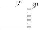
Fig. 3a shows a schematic structural view of the air duct. Figure 3b shows a schematic view of the outlet damper closed. Fig. 3c shows a schematic view when the outlet damper is open. As shown in fig. 3a, 3b, and 3c, the air duct 300 includes an air outlet 310 and an air passage 320. The air outlet is provided with an air valve 311. The air valve is controlled by the control end and can be controlled to be opened or closed. 312 are duct walls.
Fig. 1 is a method schematic diagram of an embodiment of a control method of a fresh air system provided by the present invention.
As shown in fig. 1, according to an embodiment of the present invention, the control method includes at least step S110, step S120, and step S130.
And step S110, after the fresh air system is started, determining whether the refrigerating or heating function of the fresh air system needs to be started.
In a specific embodiment, whether the cooling or heating function of the fresh air system needs to be started is determined according to a user control command. For example, after the fresh air system is powered on, the user inputs a control command, where the control command includes: at least one of a run mode command, a target temperature value command, and a respective damper switch command. And determining whether the refrigerating or heating function of the fresh air system needs to be started or not according to the operation mode command.
In another specific embodiment, whether the cooling or heating function needs to be started is determined according to a difference between the set temperature and the current indoor environment temperature. Specifically, if the difference between the set temperature and the current indoor environment temperature is greater than a preset threshold, it is determined that the refrigeration function needs to be started, and if the difference between the set temperature and the current indoor environment temperature is less than or equal to the preset threshold, it is determined that the refrigeration function does not need to be started. And if the difference value between the current indoor environment temperature and the set temperature is less than or equal to the preset threshold value, determining that the heating function does not need to be started. Wherein the preset threshold is greater than or equal to zero. Whether heating or cooling is started or not is judged according to the outdoor environment temperature, for example, when the outdoor environment temperature is greater than a first preset temperature value, whether the cooling function is started or not is judged, and when the outdoor environment temperature is less than a second preset temperature value, whether the heating function is started or not is judged.
And step S120, if the refrigeration or heating function of the fresh air system needs to be started, controlling the refrigeration and heating equipment of the outdoor unit of the fresh air system to be started, controlling the fan of the fresh air system to be started, and controlling the switch of the corresponding air valve according to a user control command.
In one embodiment, fig. 4 is a flowchart illustrating one embodiment of the steps of controlling the cooling and heating devices of the outdoor unit of the fresh air system to be turned on. As shown in fig. 4, specifically, the controlling of the opening of the cooling and heating device of the outdoor unit of the fresh air system may include step S121 and step S122.
And step S121, determining the refrigerating operation time or the heating operation time of the fresh air system according to the assembly environment parameters and the set parameters of the fresh air system.
In one embodiment, the setting parameter includes a setting temperature value (i.e., a target temperature value); the assembly environment parameters comprise the total area covered by the fresh air system unit and the area of a working object of the fresh air system unit. The total unit coverage area refers to the area where refrigeration, heating or air supply can be carried out when all air valves are opened; the unit work object area refers to an actual work area, for example, the air valves of some rooms can be closed, namely, the rooms are not worked, and the unit work object area is the total area of the opened air valves. The actual working area can be changed by opening and closing some air valves according to the requirements of users; the total unit coverage area is the determined maximum coverage area when the unit is installed, namely the area of a room covered by the air valve in a fully open mode. When the fresh air system is installed, relevant installation environment parameters can be input according to actual conditions, for example, the relevant installation environment parameters are input to a control system of the fresh air system, such as a controller or a main control board storage unit.
In one embodiment, the time length of the cooling operation or the heating operation at a set frequency is calculated according to the following formula;

wherein, T is the time length of the heat exchange device (specifically, the compressor of the heat exchange device) of the outdoor unit of the fresh air system operating according to the set frequency, unit: min; the set frequency may specifically be a maximum operating frequency of the heat exchange device (i.e. a maximum operating frequency of a compressor of the heat exchange device), tmp Ring (C) Ambient temperature value, unit: DEG C; tmp Is provided with To set temperature values, the unit: DEG C; mult is the time required to change a preset temperature value (e.g., one degree), in units of: min; a is a predetermined compensation constant, S General (1) The unit of the total area covered by the fresh air system unit is as follows: square meter; s Fruit of Chinese wolfberry The area of a working object of a fresh air system unit is as follows: square meter.
Wherein mult alpha [1- (S) Fruit of Chinese wolfberry /S General assembly )]The part is a compensation value, and the temperature diffusion among different rooms in the passive room is considered; the diffusion of the temperature in the passive room to the temperature outside the passive room has little influence and neglect due to the characteristics of high heat preservation and high air tightness of the passive room. The part aims at compensation values made for passive room buildings, when the unit only works in part of rooms, the temperature of the working room can be diffused to the non-working room.
The formula is simplified in that the heat dissipation loss is mapped to mult (the time required for a one-degree change), that is, the loss caused by heat dissipation is compensated by increasing the value of mult.
The above equation can be changed to:

that is to mult much And multiplying as a compensation value. Where the compensation constant a (an exemplary value of 0.04) is a constant that has been experimentally adapted for most situations based on a normal distribution, and needs to be modified in certain specific circumstances (e.g., extremely cold, extremely hot, extremely wet, etc.). Building parameters and geographic parameters are used as input, and the concrete value of the compensation constant a is obtained through experiments by changing the input parameters.
Formula for time per unit area change per unit temperature: formula | tmp Ring (C) -tmp Is provided with |*mult*(S Fruit of Chinese wolfberry /S General assembly ) Part where, | tmp Ring (C) -tmp Is provided with L is a temperature required change value, and mult (time required for changing once) is multiplied to obtain the total time required for reaching a set value; (S) Fruit of Chinese wolfberry /S General assembly ) In part, to address the situation where sometimes a crew opens only a portion of a room. For example, if all rooms are open, (S) Fruit of Chinese wolfberry /S General (1) )=1,|tmp Ring (C) -tmp Is provided with |*mult*(S Fruit of Chinese wolfberry /S General assembly ) The product is also equivalent to | tmp Ring(s) -tmp Is provided with | mult; if three rooms of 50 square meters are available and only two rooms are opened, | tmp Ring (C) -tmp Is provided with |*mult*(S Fruit of Chinese wolfberry /S General assembly ) The product is equal to | tmp Ring (C) -tmp Is provided with |*mult*(2/3)。
The power of an exemplary fresh air system unit is 3000W, and under the environment of a laboratory simulation passive room shown in FIG. 2:
firstly, the environment temperature is 15 ℃, the set temperature is 26 ℃, all air valves are fully opened, and the whole house heating is carried out. And (4) operating for 18.1 minutes at high frequency once, wherein the ambient temperature reaches 24.5 ℃, and the unit is closed to heat and wait for temperature transfer. After two minutes, the ambient temperature reaches the set temperature value and then the temperature is maintained.
Secondly, the ambient temperature is 15 ℃, the set temperature is 26 ℃, the air valve of the living room is opened, the other air valves are closed, and only the heating of the living room is carried out. And 7.7 minutes of operation, wherein the ambient temperature reaches 25.1 ℃, the unit is closed in heating, and temperature transfer is waited. After one minute, the living room reaches the set temperature, the bedroom reaches 15.6 ℃, the secondary bed 1 reaches 15.9 ℃, the secondary bed 2 reaches 15.4 ℃, the kitchen reaches 15.2 ℃, and the toilet basically has no change.
Thirdly, the ambient temperature is 35 ℃, the set temperature is 26 ℃, all air valves are fully opened, and the whole house refrigeration is carried out. And (3) carrying out single high-frequency operation for 14.5 minutes, wherein the ambient temperature reaches 27.5 ℃, and the refrigeration of the unit is closed to wait for temperature transfer. After two minutes, the ambient temperature reached the set temperature value.
Fourthly, the ambient temperature is 35 ℃, the set temperature is 26 ℃, the air valve of the living room is opened, the other air valves are closed, and only the heating of the living room is carried out. And (4) operating at high frequency for 6.0 minutes, wherein the ambient temperature reaches 26.6 ℃, refrigerating the unit is closed, and waiting for temperature transfer. After half a minute, the living room reaches the set temperature, the bedroom reaches 26.3 ℃, the second time of lying 1 reaches 26.2 ℃, the second time of lying 2 reaches 26.4 ℃, the kitchen reaches 26.9 ℃, and the toilet is basically unchanged.
The experiments are verified for multiple times, the experiment results all accord with the formula, and energy waste really exists according to the condition and the real-time feedback temperature value as the basis for stopping the unit.
And step S122, controlling the refrigerating and heating equipment of the outdoor unit to operate according to the determined refrigerating operation time length or heating operation time length.
Specifically, the refrigeration and heating equipment of the outdoor unit is controlled to operate according to the determined duration of the refrigeration operation or the heating operation, the fan of the fresh air system is controlled to be started, and the corresponding air valve is controlled to be opened according to a user command.
For example, after the determined cooling operation or heating operation duration T, the cooling (heating) device of the external unit is controlled to start up, so that the temperature of the refrigerant is changed; after waiting for a certain time (for example, 30S), the outer machine pumps the refrigerant into the refrigerant pipe of the inner machine; the indoor unit starts a fan, fresh air is blown through the refrigerant pipe, and is blown into the indoor air channel after the temperature is changed; fresh air reaches the air outlet along the air duct and finally enters a room through the opened air valve. This process continues until time T is reached.
And S130, if the refrigeration or heating function of the fresh air system is determined not to be required to be started, directly controlling a fan of the fresh air system to be started, and controlling the switch of the corresponding air valve according to a user control command.
Specifically, if the refrigeration or heating function does not need to be started, the fan of the internal machine is directly controlled to start, and the air valve is controlled to be switched on and off according to a user control command. For example, after the fresh air system is powered on, the user inputs a control command, where the control command includes: at least one of a run mode command, a target temperature value command, and a respective damper switch command. And determining the air valve which is opened or closed by the user according to the air valve opening and closing command, and controlling the air valve to be opened and closed according to the user control command. Fresh air is pumped into the indoor air duct by the indoor unit and finally enters the corresponding room through the air outlet with the air valve in an open state.
As shown in fig. 5, the above steps of the present invention can be implemented by a control end, and the control end includes a microprocessor, a storage medium, an input device, and an output device. The input device is not limited to an application APP, a website, a remote controller, etc.
For clearly explaining the technical solution of the present invention, the following describes an execution flow of the control method of the fresh air system provided by the present invention with a specific embodiment.
Fig. 6 is a schematic method diagram of a control method of a fresh air system according to an embodiment of the present invention. As shown in fig. 6, after the fresh air system is installed, relevant environmental parameters are input into the system through the input device of the control terminal and stored according to the installation environment. Firstly, electrifying for the first time, and automatically detecting and initializing each module, for example, comprising air valve resetting, fan test rotation and sensor fault detection; secondly, a user inputs a control command through the input equipment of the control end, and the command mainly comprises the following steps: the method comprises the steps of a unit startup and shutdown command, a unit running mode command, a target temperature value command and each room air valve opening and closing commands. And thirdly, after the control end receives the user control command, judging whether the user starts the refrigeration or heating function or not, or judging whether the refrigeration or heating function needs to be started according to the difference value between the set temperature and the current temperature, and calculating the time T for starting the refrigeration or heating function. And fourthly, if the refrigerating or heating function is not required to be started, directly controlling the starting of the fan of the inner machine, and controlling the air valve to be switched on and off according to the command of a user. Fresh air is pumped into the indoor air duct by the indoor unit and finally enters a room through the air outlet with the air valve in an open state. If the refrigeration or heating function needs to be started, controlling the refrigeration (heating) equipment of the external unit to start up so as to change the temperature of the refrigerant; after waiting for 30 seconds, the outer machine pumps the refrigerant into the refrigerant pipe of the inner machine; the indoor unit starts a fan, fresh air is blown through the refrigerant pipe, and is blown into the indoor air channel after the temperature is changed; fresh air reaches the air outlet along the air duct and finally enters a room through the opened air valve. The process continues until time T has elapsed, after which the second step state is returned. And sixthly, during the whole operation period of the unit, a user can shut down the unit or change a set value through the input device of the control end at any time.
The invention provides a control device of a fresh air system. The device can be used for the new trend system in passive room. The fresh air system can be a fresh air system with a heat exchange (refrigeration and/or heating) function.
As shown in fig. 2, the passive room fresh air system includes an outdoor unit 100, an indoor unit 200, and an air duct 300; the areas of the rooms are labeled in the figure (for example only). The outdoor unit 100 is used to change the temperature of a refrigerant and transmit the refrigerant; the indoor unit 200 is used to filter, heat or refrigerate air and pump the air into the air duct; the air duct 300 is used to transmit air. The control end is responsible for controlling the running state of the whole unit.
Fig. 3a shows a schematic structural view of the air duct. Figure 3b shows a schematic view of the outlet damper closed. Fig. 3c shows a schematic view when the outlet damper is open. As shown in fig. 3a, 3b, and 3c, the air duct 300 includes an air outlet 310 and an air passage 320. The air outlet is provided with an air valve 311. The air valve can be controlled by the control end and can be controlled to be opened or closed. 312 are duct walls.
Fig. 7 is a block diagram of a control device of a fresh air system according to an embodiment of the present invention. As shown in fig. 7, the control apparatus 100 includes a determination unit 110 and a control unit 120.
The determining unit 110 is configured to determine whether a cooling or heating function of the fresh air system needs to be started after the fresh air system is started.
In a specific embodiment, whether the cooling or heating function of the fresh air system needs to be started is determined according to a user control command. For example, after the fresh air system is powered on, the user inputs a control command, where the control command includes: at least one of a run mode command, a target temperature value command, and a respective damper switch command. And determining whether the refrigerating or heating function of the fresh air system needs to be started or not according to the operation mode command.
In another specific embodiment, whether the cooling or heating function needs to be started is determined according to a difference between the set temperature and the current indoor environment temperature. Specifically, if the difference between the set temperature and the current indoor environment temperature is greater than a preset threshold, it is determined that the refrigeration function needs to be started, and if the difference between the set temperature and the current indoor environment temperature is less than or equal to the preset threshold, it is determined that the refrigeration function does not need to be started. And if the difference value between the current indoor environment temperature and the set temperature is less than or equal to the preset threshold value, determining that the heating function does not need to be started. Wherein the preset threshold is greater than or equal to zero. Whether heating or cooling is started or not is judged according to the outdoor environment temperature, for example, when the outdoor environment temperature is greater than a first preset temperature value, whether the cooling function is started or not is judged, and when the outdoor environment temperature is less than a second preset temperature value, whether the heating function is started or not is judged.
A control unit 120, configured to control a heat exchange device of an outdoor unit of the fresh air system to be turned on, control a fan of the fresh air system to be turned on, and control a switch of a corresponding air valve according to a user control command, if the determination unit 110 determines that a cooling or heating function of the fresh air system needs to be turned on; if the determining unit 110 determines that the refrigeration or heating function of the fresh air system does not need to be started, the fan of the fresh air system is directly controlled to be started, and the switch of the corresponding air valve is controlled according to a user control command.
In one embodiment, fig. 4 is a flowchart illustrating one embodiment of the steps of controlling the opening of the cooling and heating devices of the outdoor unit of the fresh air system by the control unit. As shown in fig. 4, the step of controlling the opening of the cooling and heating device of the outdoor unit of the fresh air system by the control unit may specifically include step S121 and step S122.
And S121, determining the refrigerating operation time or the heating operation time of the fresh air system according to the assembly environment parameters and the set parameters of the fresh air system.
In one embodiment, the setting parameter includes a setting temperature value (i.e., a target temperature value); the assembly environment parameters comprise the total area covered by the fresh air system unit and the area of a working object of the fresh air system unit. The total unit coverage area refers to the area where refrigeration, heating or air supply can be carried out when all air valves are opened; the unit work object area refers to an actual work area, for example, the air valves of some rooms can be closed, namely, the rooms are not worked, and the unit work object area is the total area of the opened air valves. The actual working area can be changed by opening and closing some air valves according to the requirements of users; the total unit coverage area is the determined maximum coverage area when the unit is installed, namely the area of a room covered by the air valve in a fully open mode. When the fresh air system is installed, relevant installation environment parameters can be input according to actual conditions, for example, the relevant installation environment parameters are input to a control system of the fresh air system, such as a controller or a main control board storage unit.
In one embodiment, the time length of the cooling operation or the heating operation at a set frequency is calculated according to the following formula;

wherein, T is the time length of the heat exchange device (specifically, the compressor of the heat exchange device) of the outdoor unit of the fresh air system operating according to the set frequency, unit: min; the set frequency may specifically be a maximum operating frequency of the heat exchange device (i.e. a maximum operating frequency of a compressor of the heat exchange device), tmp Ring (C) Is an ambient temperature value, in units: DEG C; tmp Is provided with To set temperature values, the unit: DEG C; mult is the time required to change a preset temperature value (e.g., one degree), in units of: min; a is a predetermined compensation constant, S General assembly The unit of the total area covered by the fresh air system unit is as follows: square meter; s Fruit of Chinese wolfberry Is the working object area of the fresh air system unitBit: square meter.
Wherein mult alpha [1- (S) Fruit of Chinese wolfberry /S General assembly )]The part is a compensation value, and the temperature diffusion among different rooms in the passive room is considered; the diffusion of the temperature in the passive room to the temperature outside the passive room has little influence and neglect due to the characteristics of high heat preservation and high air tightness of the passive room. The part aims at compensation values made for passive room buildings, when the unit only works in part of rooms, the temperature of the working room can be diffused to the non-working room.
The formula is simplified in that the heat dissipation loss is mapped to mult (the time required for a one-degree change), that is, the loss caused by heat dissipation is compensated by increasing the value of mult.
The above equation can be changed to:

that is to mult much And multiplying as a compensation value. Where the compensation constant a (an exemplary value of 0.04) is a constant that has been experimentally adapted for most situations based on a normal distribution, and needs to be modified in certain specific circumstances (e.g., extremely cold, extremely hot, extremely wet, etc.). Building parameters and geographic parameters are used as input, and the concrete value of the compensation constant a is obtained through experiments by changing the input parameters.
Formula for time per unit area change per unit temperature: formula | tmp Ring (C) -tmp Is provided with |*mult*(S Fruit of Chinese wolfberry /S General assembly ) Part where, | tmp Ring (C) -tmp Is provided with L is the value of the temperature change required, and multiplying mult (the time required for one degree of change) to obtain the total time required for reaching the set value; (S) Fruit of Chinese wolfberry /S General (1) ) In part, to address the situation where sometimes a crew opens only a portion of a room. For example, if all rooms are open, (S) Fruit of Chinese wolfberry /S General assembly )=1,|tmp Ring (C) -tmp Is provided with |*mult*(S Fruit of Chinese wolfberry /S General (1) ) The product isEquivalent to | tmp Ring (C) -tmp Is provided with | mult; if three rooms of 50 square meters are available and only two rooms are opened, | tmp Ring (C) -tmp Is provided with |*mult*(S Fruit of Chinese wolfberry /S General assembly ) The product is equal to | tmp Ring (C) -tmp Is provided with |*mult*(2/3)。
And step S122, controlling the refrigerating and heating equipment of the outdoor unit to operate according to the determined refrigerating operation time length or heating operation time length.
Specifically, the refrigeration and heating equipment of the outdoor unit is controlled to operate according to the determined duration of the refrigeration operation or the heating operation, the fan of the fresh air system is controlled to be started, and the corresponding air valve is controlled to be opened according to a user command.
For example, after the determined cooling operation or heating operation duration T, the cooling (heating) device of the external unit is controlled to start up, so that the temperature of the refrigerant is changed; after waiting for a certain time (for example, 30S), the outer machine pumps the refrigerant into the refrigerant pipe of the inner machine; the indoor unit starts a fan, fresh air is blown through the refrigerant pipe, and the fresh air is blown into the indoor air duct after the temperature is changed; fresh air reaches the air outlet along the air duct and finally enters a room through the opened air valve. This process continues until time T is reached.
If the determining unit 110 determines that the cooling or heating function of the fresh air system does not need to be started, the control unit 120 directly controls the fan of the fresh air system to be started, and controls the switch of the corresponding air valve according to a user control command.
Specifically, if the refrigeration or heating function does not need to be started, the fan of the internal machine is directly controlled to start, and the air valve is controlled to be switched on and off according to a user control command. For example, after the fresh air system is powered on, the user inputs a control command, where the control command includes: at least one of a run mode command, a target temperature value command, and a respective damper switch command. And determining the air valve which is opened or closed by the user according to the air valve opening and closing command, and controlling the air valve to be opened and closed according to the user control command. Fresh air is pumped into the indoor air duct by the indoor unit and finally enters the corresponding room through the air outlet with the air valve in an open state.
The invention also provides a storage medium corresponding to the control method of the fresh air system, and a computer program is stored on the storage medium, and when the program is executed by a processor, the steps of any one of the methods are realized.
The invention also provides a fresh air system corresponding to the control method of the fresh air system, which comprises a processor, a memory and a computer program which is stored in the memory and can run on the processor, wherein the processor executes the program to realize the steps of any one of the methods.
The invention also provides a fresh air system corresponding to the control device of the fresh air system, which comprises the control device of any one of the fresh air systems.
Therefore, the scheme provided by the invention is based on the characteristics of the passive room and controls the refrigerating/heating capacity in the single high-frequency mode. According to the technical scheme of the invention, the power consumption of the system can be reduced, and the temperature and humidity regulation rate can be improved. Through experimental tests, compared with a traditional fresh air system, the system power consumption is reduced by 15%, the temperature and humidity adjusting capacity of the system is improved by 30%, and the temperature and humidity parameter reaches the comfortable curve speed and is improved by 30%.
The functions described herein may be implemented in hardware, software executed by a processor, firmware, or any combination thereof. If implemented in software executed by a processor, the functions may be stored on or transmitted over as one or more instructions or code on a computer-readable medium. Other examples and implementations are within the scope and spirit of the invention and the following claims. For example, due to the nature of software, the functions described above may be implemented using software executed by a processor, hardware, firmware, hardwired, or a combination of any of these. In addition, each functional unit may be integrated into one processing unit, or each unit may exist alone physically, or two or more units are integrated into one unit.
In the embodiments provided in the present application, it should be understood that the disclosed technical content can be implemented in other manners. The above-described embodiments of the apparatus are merely illustrative, and for example, the division of the units may be a logical division, and in actual implementation, there may be another division, for example, multiple units or components may be combined or integrated into another system, or some features may be omitted, or not executed. In addition, the shown or discussed mutual coupling or direct coupling or communication connection may be an indirect coupling or communication connection through some interfaces, units or modules, and may be in an electrical or other form.
The units described as separate parts may or may not be physically separate, and the parts serving as the control device may or may not be physical units, may be located in one place, or may be distributed on a plurality of units. Some or all of the units can be selected according to actual needs to achieve the purpose of the solution of the embodiment.
The integrated unit, if implemented in the form of a software functional unit and sold or used as a stand-alone product, may be stored in a computer readable storage medium. Based on such understanding, the technical solution of the present invention may be embodied in the form of a software product, which is stored in a storage medium and includes instructions for causing a computer device (which may be a personal computer, a server, or a network device) to execute all or part of the steps of the method according to the embodiments of the present invention. And the aforementioned storage medium includes: a U-disk, a Read-Only Memory (ROM), a Random Access Memory (RAM), a removable hard disk, a magnetic or optical disk, and other various media capable of storing program codes.
The above description is only an example of the present invention, and is not intended to limit the present invention, and it is obvious to those skilled in the art that various modifications and variations can be made in the present invention. Any modification, equivalent replacement, or improvement made within the spirit and principle of the present invention should be included in the scope of the claims of the present invention.
Claims (10)
1. The control method of the fresh air system is characterized in that the fresh air system has a heat exchange function, and the heat exchange function is a refrigerating or heating function; the control method comprises the following steps:
after the fresh air system is started, determining whether the refrigerating or heating function of the fresh air system needs to be started;
if the refrigeration or heating function of the fresh air system needs to be started, the heat exchange equipment of the outdoor unit of the fresh air system is controlled to be started, a fan of the fresh air system is controlled to be started, and the switch of the corresponding air valve is controlled according to a user control command;
and if the refrigeration or heating function of the fresh air system is determined not to be started, directly controlling the fan of the fresh air system to be started, and controlling the switch of the corresponding air valve according to a user control command.
2. The control method of claim 1, wherein determining whether a cooling or heating function of the fresh air system needs to be turned on comprises:
determining whether the refrigeration or heating function of the fresh air system needs to be started or not according to a user control command;
and/or the presence of a gas in the gas,
and judging whether the refrigeration or heating function needs to be started or not according to the difference value between the set temperature and the current indoor environment temperature.
3. The control method of claim 1 or 2, wherein controlling the cooling and heating devices of the outdoor unit of the fresh air system to be turned on comprises:
determining the refrigerating operation or heating operation duration of the fresh air system according to the assembly environment parameters and the set parameters of the fresh air system;
and controlling the refrigerating and heating equipment of the outdoor unit to operate according to the determined refrigerating operation time or heating operation time.
4. The control method according to claim 3, wherein determining the cooling operation or heating operation duration of the fresh air system according to the assembly environment parameter and the setting parameter of the fresh air system comprises:
calculating the time length of the heat exchange equipment of the outdoor unit of the fresh air system in refrigerating operation or heating operation according to a set frequency according to the following formula;

wherein T is the running time length of the heat exchange equipment according to the set frequency, tmp Ring (C) For ambient temperature values, tmp Is provided with For setting the temperature value, mult is the time required for changing the preset temperature value, S General assembly For the total area covered by the fresh air system unit, S Fruit of Chinese wolfberry The area of a working object of the fresh air system unit.
5. The control device of the fresh air system is characterized in that the fresh air system has a heat exchange function, and the heat exchange function is a refrigerating or heating function; the control device includes:
the determining unit is used for determining whether the refrigerating or heating function of the fresh air system needs to be started or not after the fresh air system is started;
the control unit is used for controlling the opening of heat exchange equipment of an outdoor unit of the fresh air system, controlling the opening of a fan of the fresh air system and controlling the opening and closing of a corresponding air valve according to a user control command if the determination unit determines that the refrigeration or heating function of the fresh air system needs to be started; and if the refrigeration or heating function of the fresh air system is determined not to be started, directly controlling a fan of the fresh air system to be started, and controlling the switch of the corresponding air valve according to a user control command.
6. The control device according to claim 5, wherein the determining unit determines whether a cooling or heating function of the fresh air system needs to be turned on, and includes:
determining whether a refrigerating or heating function of the fresh air system needs to be started or not according to a user control command;
and/or the presence of a gas in the gas,
and judging whether the refrigeration or heating function needs to be started or not according to the difference value between the set temperature and the current indoor environment temperature.
7. The control device according to claim 5 or 6, wherein the control unit controls the opening of the cooling and heating device of the outdoor unit of the fresh air system, and comprises:
determining the refrigerating operation or heating operation duration of the fresh air system according to the assembly environment parameters and the set parameters of the fresh air system;
and controlling the refrigerating and heating equipment of the outdoor unit to operate according to the determined refrigerating operation time or heating operation time.
8. The control device according to claim 7, wherein the control unit determines the duration of the cooling operation or the heating operation of the fresh air system according to the assembly environment parameter and the setting parameter of the fresh air system, and comprises:
calculating the time length of the heat exchange equipment of the outdoor unit of the fresh air system in refrigerating operation or heating operation according to a set frequency according to the following formula;

wherein T is the running time length of the heat exchange equipment according to the set frequency, tmp Ring (C) For ambient temperature values, tmp Is provided with For setting the temperature value, mult is the time required for changing the preset temperature value, S General assembly For the total area covered by the fresh air system unit, S Fruit of Chinese wolfberry The area of a working object of the fresh air system unit.
9. A storage medium, having stored thereon a computer program which, when being executed by a processor, carries out the steps of the method of any one of claims 1 to 4.
10. A ventilation system comprising a processor, a memory, and a computer program stored on the memory and operable on the processor, the processor executing the program to perform the steps of the method of any of claims 1 to 4, or the ventilation system comprising control means for a ventilation system according to any of claims 5 to 8.
Priority Applications (1)
| Application Number | Priority Date | Filing Date | Title |
|---|---|---|---|
| CN202210758582.4A CN115013912A (en) | 2022-06-30 | 2022-06-30 | Control method and device of fresh air system, storage medium and fresh air system |
Applications Claiming Priority (1)
| Application Number | Priority Date | Filing Date | Title |
|---|---|---|---|
| CN202210758582.4A CN115013912A (en) | 2022-06-30 | 2022-06-30 | Control method and device of fresh air system, storage medium and fresh air system |
Publications (1)
| Publication Number | Publication Date |
|---|---|
| CN115013912A true CN115013912A (en) | 2022-09-06 |
Family
ID=83078951
Family Applications (1)
| Application Number | Title | Priority Date | Filing Date |
|---|---|---|---|
| CN202210758582.4A Pending CN115013912A (en) | 2022-06-30 | 2022-06-30 | Control method and device of fresh air system, storage medium and fresh air system |
Country Status (1)
| Country | Link |
|---|---|
| CN (1) | CN115013912A (en) |
Citations (11)
| Publication number | Priority date | Publication date | Assignee | Title |
|---|---|---|---|---|
| US20050156052A1 (en) * | 2004-01-16 | 2005-07-21 | Bartlett Charles E. | Fresh air ventilation control methods and systems |
| CN107514749A (en) * | 2017-08-22 | 2017-12-26 | 广东美的暖通设备有限公司 | Multi-connected machine VMC and its control method, computer-readable recording medium |
| CN109282451A (en) * | 2018-09-30 | 2019-01-29 | 珠海格力电器股份有限公司 | Aeration device control method |
| CN109751730A (en) * | 2018-12-19 | 2019-05-14 | 广东美的暖通设备有限公司 | Control method, system, air conditioner and the storage medium of air conditioner |
| CN110388692A (en) * | 2019-07-11 | 2019-10-29 | 博乐环境系统(苏州)有限公司 | Cooling and Heat Source aeration device and its control method for nearly zero energy consumption building |
| CN110388693A (en) * | 2019-07-11 | 2019-10-29 | 博乐环境系统(苏州)有限公司 | Space air environment conditioning system and its control method |
| CN112050439A (en) * | 2019-06-06 | 2020-12-08 | 青岛海尔空调器有限总公司 | Control method of fresh air conditioner |
| CN113432257A (en) * | 2021-06-22 | 2021-09-24 | Tcl空调器(中山)有限公司 | Fresh air function control method and device for air conditioner, air conditioner and storage medium |
| CN113483474A (en) * | 2021-06-17 | 2021-10-08 | 珠海拓芯科技有限公司 | Layered refrigeration temperature control method and device, air conditioner and computer readable storage medium |
| WO2021227801A1 (en) * | 2020-05-13 | 2021-11-18 | 广东美的制冷设备有限公司 | Control method for air conditioner, air conditioner, and readable storage medium |
| CN114151913A (en) * | 2021-11-12 | 2022-03-08 | 宁波奥克斯电气股份有限公司 | Control method and device of fresh air conditioner and fresh air conditioner |
-
2022
- 2022-06-30 CN CN202210758582.4A patent/CN115013912A/en active Pending
Patent Citations (11)
| Publication number | Priority date | Publication date | Assignee | Title |
|---|---|---|---|---|
| US20050156052A1 (en) * | 2004-01-16 | 2005-07-21 | Bartlett Charles E. | Fresh air ventilation control methods and systems |
| CN107514749A (en) * | 2017-08-22 | 2017-12-26 | 广东美的暖通设备有限公司 | Multi-connected machine VMC and its control method, computer-readable recording medium |
| CN109282451A (en) * | 2018-09-30 | 2019-01-29 | 珠海格力电器股份有限公司 | Aeration device control method |
| CN109751730A (en) * | 2018-12-19 | 2019-05-14 | 广东美的暖通设备有限公司 | Control method, system, air conditioner and the storage medium of air conditioner |
| CN112050439A (en) * | 2019-06-06 | 2020-12-08 | 青岛海尔空调器有限总公司 | Control method of fresh air conditioner |
| CN110388692A (en) * | 2019-07-11 | 2019-10-29 | 博乐环境系统(苏州)有限公司 | Cooling and Heat Source aeration device and its control method for nearly zero energy consumption building |
| CN110388693A (en) * | 2019-07-11 | 2019-10-29 | 博乐环境系统(苏州)有限公司 | Space air environment conditioning system and its control method |
| WO2021227801A1 (en) * | 2020-05-13 | 2021-11-18 | 广东美的制冷设备有限公司 | Control method for air conditioner, air conditioner, and readable storage medium |
| CN113483474A (en) * | 2021-06-17 | 2021-10-08 | 珠海拓芯科技有限公司 | Layered refrigeration temperature control method and device, air conditioner and computer readable storage medium |
| CN113432257A (en) * | 2021-06-22 | 2021-09-24 | Tcl空调器(中山)有限公司 | Fresh air function control method and device for air conditioner, air conditioner and storage medium |
| CN114151913A (en) * | 2021-11-12 | 2022-03-08 | 宁波奥克斯电气股份有限公司 | Control method and device of fresh air conditioner and fresh air conditioner |
Similar Documents
| Publication | Publication Date | Title |
|---|---|---|
| US9702578B2 (en) | Air conditioning control system for controlling outside air control and return air control of air conditioning system | |
| EP1632737B1 (en) | Air-conditioner and method for controlling driving thereof | |
| WO2019223301A1 (en) | Air conditioner control method and control device and air conditioner using the method | |
| CN103388856A (en) | Multi-split air conditioner system and quick-starting heat generation method | |
| CN108644979A (en) | Control method, control system and the air conditioner of air conditioner | |
| KR100661919B1 (en) | Driving control method for unitary air conditioner | |
| CN106839332B (en) | Linkage control method, linkage control device and multi-connected air conditioner | |
| KR20010056530A (en) | Multi airconditioner | |
| CN112128941A (en) | Fresh air conditioner, control method thereof and computer readable storage medium | |
| CN110207325B (en) | Method for controlling air conditioning system and air conditioning system | |
| CN107642879B (en) | Control method and device of air conditioning system and air conditioner | |
| CN103673107A (en) | Air conditioner and control method and device thereof | |
| CN108278723A (en) | The control method of air-conditioning | |
| JP2000088316A (en) | Equipment for determining set temperature, air conditioning equipment and program recording medium | |
| JP7403669B2 (en) | Ventilation alarm device and ventilation alarm program | |
| KR20050111281A (en) | Unitary air conditioner and his control method | |
| KR100619733B1 (en) | Driving control method for unitary air conditioner | |
| CN110822634A (en) | Self-adaptive dynamic control method for compressor during refrigeration of capillary radiation air conditioner | |
| CN112880148B (en) | Control method and device for air conditioner, electronic equipment and storage medium | |
| JP2010145012A (en) | Heat exchange type ventilation device | |
| EP4279823A1 (en) | Hydraulic module control system of floor heating multi-split air conditioner and control method thereof | |
| JP5730689B2 (en) | Air conditioning operation control system | |
| CN115013912A (en) | Control method and device of fresh air system, storage medium and fresh air system | |
| CN113587249B (en) | Multi-split system | |
| KR20040003707A (en) | Method for controlling compressor frequency for airconditioner |
Legal Events
| Date | Code | Title | Description |
|---|---|---|---|
| PB01 | Publication | ||
| PB01 | Publication | ||
| SE01 | Entry into force of request for substantive examination | ||
| SE01 | Entry into force of request for substantive examination |