CN115006925A - Industrial boiler with flue gas dust removal function - Google Patents
Industrial boiler with flue gas dust removal function Download PDFInfo
- Publication number
- CN115006925A CN115006925A CN202210677640.0A CN202210677640A CN115006925A CN 115006925 A CN115006925 A CN 115006925A CN 202210677640 A CN202210677640 A CN 202210677640A CN 115006925 A CN115006925 A CN 115006925A
- Authority
- CN
- China
- Prior art keywords
- flue gas
- cover
- pipe
- dust removal
- rotating
- Prior art date
- Legal status (The legal status is an assumption and is not a legal conclusion. Google has not performed a legal analysis and makes no representation as to the accuracy of the status listed.)
- Withdrawn
Links
Images


Classifications
-
- B—PERFORMING OPERATIONS; TRANSPORTING
- B01—PHYSICAL OR CHEMICAL PROCESSES OR APPARATUS IN GENERAL
- B01D—SEPARATION
- B01D46/00—Filters or filtering processes specially modified for separating dispersed particles from gases or vapours
- B01D46/02—Particle separators, e.g. dust precipitators, having hollow filters made of flexible material
- B01D46/04—Cleaning filters
-
- B—PERFORMING OPERATIONS; TRANSPORTING
- B01—PHYSICAL OR CHEMICAL PROCESSES OR APPARATUS IN GENERAL
- B01D—SEPARATION
- B01D46/00—Filters or filtering processes specially modified for separating dispersed particles from gases or vapours
- B01D46/42—Auxiliary equipment or operation thereof
- B01D46/4227—Manipulating filters or filter elements, e.g. handles or extracting tools
-
- B—PERFORMING OPERATIONS; TRANSPORTING
- B01—PHYSICAL OR CHEMICAL PROCESSES OR APPARATUS IN GENERAL
- B01D—SEPARATION
- B01D46/00—Filters or filtering processes specially modified for separating dispersed particles from gases or vapours
- B01D46/56—Filters or filtering processes specially modified for separating dispersed particles from gases or vapours with multiple filtering elements, characterised by their mutual disposition
- B01D46/62—Filters or filtering processes specially modified for separating dispersed particles from gases or vapours with multiple filtering elements, characterised by their mutual disposition connected in series
-
- B—PERFORMING OPERATIONS; TRANSPORTING
- B01—PHYSICAL OR CHEMICAL PROCESSES OR APPARATUS IN GENERAL
- B01D—SEPARATION
- B01D47/00—Separating dispersed particles from gases, air or vapours by liquid as separating agent
- B01D47/06—Spray cleaning
-
- B—PERFORMING OPERATIONS; TRANSPORTING
- B01—PHYSICAL OR CHEMICAL PROCESSES OR APPARATUS IN GENERAL
- B01D—SEPARATION
- B01D50/00—Combinations of methods or devices for separating particles from gases or vapours
- B01D50/60—Combinations of devices covered by groups B01D46/00 and B01D47/00
-
- B—PERFORMING OPERATIONS; TRANSPORTING
- B01—PHYSICAL OR CHEMICAL PROCESSES OR APPARATUS IN GENERAL
- B01D—SEPARATION
- B01D2258/00—Sources of waste gases
- B01D2258/02—Other waste gases
- B01D2258/0283—Flue gases
-
- Y—GENERAL TAGGING OF NEW TECHNOLOGICAL DEVELOPMENTS; GENERAL TAGGING OF CROSS-SECTIONAL TECHNOLOGIES SPANNING OVER SEVERAL SECTIONS OF THE IPC; TECHNICAL SUBJECTS COVERED BY FORMER USPC CROSS-REFERENCE ART COLLECTIONS [XRACs] AND DIGESTS
- Y02—TECHNOLOGIES OR APPLICATIONS FOR MITIGATION OR ADAPTATION AGAINST CLIMATE CHANGE
- Y02A—TECHNOLOGIES FOR ADAPTATION TO CLIMATE CHANGE
- Y02A50/00—TECHNOLOGIES FOR ADAPTATION TO CLIMATE CHANGE in human health protection, e.g. against extreme weather
- Y02A50/20—Air quality improvement or preservation, e.g. vehicle emission control or emission reduction by using catalytic converters
- Y02A50/2351—Atmospheric particulate matter [PM], e.g. carbon smoke microparticles, smog, aerosol particles, dust
Landscapes
- Chemical & Material Sciences (AREA)
- Chemical Kinetics & Catalysis (AREA)
- Chimneys And Flues (AREA)
Abstract
The invention belongs to the technical field of industrial boilers, in particular to an industrial boiler with a flue gas dust removal function, and aims at solving the problems that the existing industrial boiler is lack of dust cleaning equipment, blockage is easy to cause, and dust cannot be reduced well. The invention has the advantages of conveniently realizing the filtering and cleaning of the smoke dust in the smoke and conveniently cleaning and preventing the blockage of the interior of the smoke guide pipe.
Description
Technical Field
The invention relates to the technical field of industrial boilers, in particular to an industrial boiler with a flue gas dust removal function.
Background
The boiler is an energy conversion device, energy input to the boiler comprises chemical energy and electric energy in fuel, the boiler outputs steam, high-temperature water or an organic heat carrier with certain heat energy, the origin of the boiler refers to a water container heated on fire, the boiler refers to a place where the fuel is combusted, the boiler comprises a boiler and a boiler, hot water or steam generated in the boiler can directly provide heat energy required by industrial production and people life, the hot water or steam can be converted into mechanical energy through a steam power device, or the mechanical energy is converted into the electric energy through a generator, the boiler for providing the hot water is called a hot water boiler and is mainly used for life, a small amount of application is realized in the industrial production, the boiler for generating the steam is called a steam boiler for short, smoke can appear when the boiler is combusted, and the modern boiler generally utilizes the waste heat of the smoke to heat the inside again.
Inside its pipeline can adhere to a large amount of dusts usually when using in traditional boiler, leads to the inside heat conduction efficiency variation of pipeline easily after long-time use, and the smoke and dust also can discharge in the air of external world along with it simultaneously, influences the environment, and traditional equipment also can't be timely when using clears up, just leads to the dust to be accumulated constantly, finally leads to the condition of jam to take place.
Disclosure of Invention
The industrial boiler with the flue gas dedusting function provided by the invention solves the problems that the traditional boiler is lack of dust cleaning equipment, is easy to cause blockage and cannot well reduce the dust emission.
In order to achieve the purpose, the invention adopts the following technical scheme:
the utility model provides an industrial boiler with flue gas dust removal function, the induction cooker comprises a cooker bod, the one end of furnace body is provided with the connection cover, the furnace body is kept away from the one end of connection cover and is installed the fixed plate, one side fixedly connected with that the furnace body was kept away from to the fixed plate holds the cover, the top intercommunication that holds the cover has the pipe of discharging fume, the inside of the pipe of discharging fume is provided with the filter bag, the inside bottom of furnace body is run through and is provided with the combustion tube, the top of combustion tube is provided with out the tobacco pipe, the combustion tube is close to the inside one end of connection cover and is provided with rotating vane, rotating vane's outer wall is to encircle and installs drive assembly, the connection cover is close to the rotating vane top and is provided with the filter screen, the top of filter screen is provided with the baffle, drive assembly's bottom is connected with connecting gear, the inside slope that holds the cover is provided with the slope filter board, the inside one end of being close to going out the tobacco pipe that holds the cover is provided with and encircles the impeller, encircle the both ends of impeller all install vibrations subassembly.
Preferably, the transmission assembly comprises a rotating ring, a driven wheel and a moving piece, the top of the rotating ring is connected with the driven wheel in a meshed mode, the moving piece is connected to one side of the edge of the outer wall of the driven wheel in a rotating mode, and the top of the moving piece is connected with the baffle in a rotating mode.
Preferably, the driven wheel is rotatably connected with the side wall of the connecting cover through a bearing, the outer wall of the rotating ring is rotatably connected with one side of the connecting cover in a penetrating mode, a partition plate is arranged inside the connecting cover, a through hole corresponding to the rotating ring and the baffle plate is formed in the partition plate, and the center of the rotating ring is fixedly connected with the outer wall of the rotating blade.
Preferably, the vibrations subassembly includes axis of rotation, eccentric block and fixed block, the equal fixedly connected with eccentric block in both ends of axis of rotation, and the high-end bearing and the fixed block mutual rotation that all pass through of axis of rotation are connected, and the one end of axis of rotation is provided with the rotation motor.
Preferably, the axis of rotation runs through the inside around the impeller, goes out the tobacco pipe and encircles and be provided with the safety cover near the inside outer wall of furnace body, and the one end of going out the tobacco pipe runs through the fixed plate and reachs the inside that holds the cover, and the fixed block is fixed with a tobacco pipe interconnect, encircles impeller outer wall blade and is the arc.
Preferably, the inside cavity that holds the cover, and hold the inside bottom of cover and be provided with the slope filter to the one side slope of fixed plate, the top of baffle is provided with the pipe, and the one side that the fixed plate was kept away from to the slope filter leads to pipe and pipe top interconnect.
Preferably, one side that the bottom of tub of discharging fume is close to the fixed plate is provided with a plurality of shower, and a plurality of spray holes have been seted up to the bottom of shower, and one section of shower is run through the tub lateral wall of discharging fume and is connected with the feed liquor pipe, and the intraduct filter bag top corner of discharging fume all is through connecting wire and tub interconnect of discharging fume.
Preferably, the inner wall one side of the connecting cover is provided with a sliding chute corresponding to the baffle, the two sides of the baffle are provided with a plurality of adjusting spray heads, the two ends of the bottom of the baffle are fixedly connected with extrusion springs, and the ends of the extrusion springs far away from the baffle are mutually fixed with the connecting cover.
Preferably, the connecting cover is internally provided with a connecting gear close to the bottom plate of the transmission assembly, the connecting gear is meshed with the outer wall of the rotating ring, the rotating rod is arranged inside the connecting gear in a penetrating mode, and the driving motor is connected to one end of the rotating rod in a penetrating mode.
Compared with the prior art, the invention has the beneficial effects that:
1. when in use, the rotation of the driving motor drives the connecting gear to rotate, thereby realizing the drive of the transmission assembly, further leading the rotating ring to drive the internal rotating blade to rotate, realizing the flow of air, further leading the smoke to be input into the internal bottom end of the connecting cover, passing through the filter screen and reaching the internal top end of the connecting cover, carrying out preliminary spray dust removal through the adjusting nozzle in the baffle, further realizing preliminary filtration, reaching the internal part of the containing cover through the smoke outlet pipe, starting the spray pipe to carry out spray dust removal adsorption, further realizing filtration, leading the smoke to move towards the surface surrounding the impeller when being sprayed out through the smoke outlet pipe to drive the rotation of the smoke outlet pipe, wetting the surrounding impeller under the action of the liquid sprayed out by the spray pipe, further directly improving the contact efficiency of the smoke and the liquid, improving the absorption of impurities in the smoke, when the smoke moves towards the top of the smoke exhaust pipe, the filter bag can further realize further filtering effect and can fully realize the aim of dust removal.
2. When the device is used, the rotating ring drives the top driven wheel to rotate, so that the moving piece drives the baffle to move in a reciprocating manner along the sliding groove, one end of the smoke outlet pipe is opened and shielded in an intermittent manner, intermittent smoke air flow with different sizes can be well formed to pass through the smoke outlet pipe, dust attached to the inside of the smoke outlet pipe is further driven to fall off, the smoke outlet pipe can be well conveyed to the inside of the containing cover, crops are reduced, meanwhile, the smoke outlet pipe is driven to rotate unevenly when the smoke outlet pipe rotates around the impeller, the smoke outlet pipe is driven to vibrate through the fixing block, the crops are further led to fall off, meanwhile, the adjusting spray heads are arranged on two sides of the baffle, when cleaning is needed, the adjusting spray heads facing one side of the smoke outlet pipe can be started, so that the inside of the smoke outlet pipe is further flushed, cleaning is realized, and the air flow of the smoke is different in size, and then its blowing to the pipe top of discharging fume filter the bag also forms intermittent type formula, and can make the filter bag also can follow and swing, and then make the attached crop of its inner wall shake off very conveniently, need not artifical clearance.
Drawings
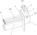
FIG. 1 is a schematic view of an industrial boiler with flue gas dust removal function according to the present invention;
FIG. 2 is a side view of the structure of an industrial boiler with flue gas dust removal function according to the present invention;
FIG. 3 is a schematic view of the inside of an industrial boiler body with a flue gas dust removal function according to the present invention;
FIG. 4 is a schematic view of the internal structure of the connecting cover of the industrial boiler with the flue gas dust removal function according to the present invention;
FIG. 5 is a schematic view of the internal structure of a rotating assembly of an industrial boiler with a flue gas dust removal function according to the present invention
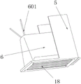
FIG. 6 is a schematic view of the internal structure of an industrial boiler accommodating cover with a flue gas dust removal function according to the present invention;
fig. 7 is a schematic structural diagram of the inside of a smoke exhaust pipe of an industrial boiler with a smoke dust removal function according to the present invention.
In the figure: 1. a furnace body; 2. a connecting cover; 201. a partition plate; 3. a fixing plate; 4. an accommodating cover; 5. a smoke exhaust pipe; 6. a filter bag; 601. a connecting wire; 7. a combustion tube; 8. discharging the smoke tube; 801. a protective cover; 9. a rotor blade; 10. a filter screen; 11. a baffle plate; 111. adjusting the spray head; 112. a conduit; 113. a compression spring; 12. a transmission assembly; 121. a rotating ring; 122. a driven wheel; 123. moving the sheet; 13. a connecting gear; 131. rotating the rod; 132. a drive motor; 14. a chute; 15. inclining the filter plate; 16. surrounding the impeller; 17. a vibration assembly; 171. a rotating shaft; 172. an eccentric block; 173. a fixed block; 18. a shower pipe; 181. a liquid inlet pipe.
Detailed Description
The technical solutions in the embodiments of the present invention will be clearly and completely described below with reference to the drawings in the embodiments of the present invention, and it is obvious that the described embodiments are only a part of the embodiments of the present invention, and not all of the embodiments.
Referring to fig. 1-7, an industrial boiler with flue gas dust removal function comprises a boiler body 1, a connecting cover 2 is arranged at one end of the boiler body 1, a fixing plate 3 is arranged at one end of the boiler body 1 far away from the connecting cover 2, a containing cover 4 is fixedly connected to one side of the fixing plate 3 far away from the boiler body 1, a smoke exhaust pipe 5 is communicated with the top of the containing cover 4, a filter bag 6 is arranged inside the smoke exhaust pipe 5, a combustion pipe 7 is arranged at the bottom end inside the boiler body 1 in a penetrating manner, a smoke outlet pipe 8 is arranged at the top of the combustion pipe 7, a rotating blade 9 is arranged at one end of the combustion pipe 7 close to the inside of the connecting cover 2, a transmission component 12 is arranged on the outer wall of the rotating blade 9 in a surrounding manner, a filter screen 10 is arranged at the top of the connecting cover 2 close to the rotating blade 9, a baffle 11 is arranged at the top of the filter screen 10, a connecting gear 13 is connected at the bottom of the transmission component 12, and an inclined filter screen 15 is arranged inside the containing cover 4 in an inclined manner, one end of the interior of the containing cover 4 close to the smoke outlet pipe 8 is provided with a surrounding impeller 16, and two ends of the surrounding impeller 16 are provided with vibration assemblies 17.
Further, in the above technical solution, the transmission assembly 12 includes a rotation ring 121, a driven wheel 122 and a moving plate 123, the top of the rotation ring 121 is engaged with the driven wheel 122, and one side of the outer wall edge of the driven wheel 122 is rotatably connected with the moving plate 123, the top of the moving plate 123 is rotatably connected with the baffle plate 11, the driven wheel 122 is rotatably connected with the side wall of the connection cover 2 through a bearing, the outer wall of the rotation ring 121 is rotatably connected with one side of the connection cover 2 in a penetrating manner, a partition plate 201 is arranged inside the connection cover 2, a through hole corresponding to the rotation ring 121 and the baffle plate 11 is formed inside the partition plate 201, the center of the rotation ring 121 is fixedly connected with the outer wall of the rotation blade 9, when in use, the rotation ring 121 can well drive the rotation of the top driven wheel 122, so that the moving plate 123 is driven to realize reciprocating movement, and further can drive the baffle plate 11 at the top to move in a reciprocating manner along the sliding groove 14, and then realize opening and sheltering from going out tobacco pipe 8 one end of intermittent type formula, intermittent type formula flue gas air current that formation variation in size that can be fine passes through the tobacco pipe 8, and then drives its inside adnexed dust and drops.
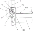
Further, in the above technical solution, the vibration assembly 17 includes a rotation shaft 171, an eccentric block 172 and a fixed block 173, both ends of the rotation shaft 171 are fixedly connected with the eccentric block 172, the high end of the rotation shaft 171 in the next year is rotatably connected with the fixed block 173 through a bearing, one end of the rotation shaft 171 is provided with a rotation motor, the rotation shaft 171 penetrates through the inside of the impeller 16, the outer wall of the smoke outlet pipe 8 near the inside of the furnace body 1 is provided with a protective cover 801 in a surrounding manner, one end of the smoke outlet pipe 8 penetrates through the fixed plate 3 to reach the inside of the containing cover 4, the fixed block 173 and the smoke outlet pipe 8 are fixedly connected with each other, and blades surrounding the outer wall of the impeller 16 are arc-shaped, the eccentric mass 172 can be rotated by the rotating shaft 171 of the vibration assembly 17 while rotating around the impeller 16, thereby driving the tobacco pipe to rotate unevenly, further driving the tobacco pipe 8 to vibrate through the fixing block 173, and further causing the attached crops to fall off.
Further, in last technical scheme, hold the inside cavity of cover 4, and hold the inside bottom of cover 4 and be provided with slope filter 15 to the lopsidedness of fixed plate 3, the top of baffle 11 is provided with pipe 112, slope filter 15 keeps away from one side of fixed plate 3 and leads to pipe and pipe 112 top interconnect, the inner wall one side of connecting cover 2 is seted up and is corresponded gliding spout 14 with baffle 11, the both sides of baffle 11 all are provided with a plurality of regulation shower nozzles 111, the equal fixedly connected with extrusion spring 113 in bottom both ends of baffle 11, and extrusion spring 113 keeps away from the one end of baffle 11 and is connected cover 2 reciprocal anchorage, because shower 18 spun washing liquid can filter the back through the slope filter 15 of this bottom, the rethread pipe 112 is carried in baffle 11, the effectual utilization efficiency that has improved liquid.
Further, in last technical scheme, one side that the bottom of tub 5 of discharging fume is close to fixed plate 3 is provided with a plurality of shower 18, a plurality of holes that spray have been seted up to the bottom of shower 18, one section of shower 18 runs through tub 5 lateral wall of discharging fume and is connected with feed liquor pipe 181, the inside filter bag 6 top corners of crossing of tub 5 of discharging fume all through connecting wire 601 and tub 5 interconnect of discharging fume, can pass through the filter screen 10 of bottom, reach the inside top of connecting cover 2, carry out preliminary spraying through the inside regulation shower nozzle of baffle 11 and remove dust, and then realized preliminary filtration, and the flue gas can also be through the inside that goes out tobacco pipe 8 once more through furnace body 1, reach and hold inside cover 4, start shower 18 and spray dust removal absorption, realization filtration that can step forward.
Further, in last technical scheme, the inside bottom plate that is close to transmission assembly 12 of connecting cover 2 is provided with connecting gear 13, and connecting gear 13 and swivel ring 121 outer wall intermeshing, connecting gear 13's inside is run through and is provided with dwang 131, the one end through connection cover 2's of dwang 131 internal connection has driving motor 132, start driving motor 132's rotation, and then make it rotate through dwang 131 drive connecting gear 13, thereby realize the drive to transmission assembly 12, and then make swivel ring 121 drive inside rotor blade 9 rotatory, realize the flow of air, and then input the flue gas that the burning produced to the inside bottom of connecting cover 2.
The working principle is as follows: when in use, the burner can be placed at one end of the combustion tube 7, so that flame can reach the inside of the combustion tube 7, combustion is realized, the inside of a boiler is heated, the rotation of the driving motor 132 is started simultaneously, and the flame can drive the connecting gear 13 to rotate through the rotating rod 131, so that the driving of the transmission component 12 is realized, the rotating ring 121 drives the internal rotating blades 9 to rotate, air flowing is realized, the flue gas generated by combustion is input to the bottom end inside the connecting cover 2, meanwhile, the flue gas can reach the top end inside the connecting cover 2 through the filter screen 10 at the bottom end, preliminary spray dust removal is performed through the adjusting nozzle inside the baffle plate 11, preliminary filtration is realized, the flue gas can also pass through the inside of the furnace body 1 again through the smoke outlet pipe 8 and reach the inside of the accommodating cover 4, and the spray pipe 18 is started for spray dust removal adsorption, the filtering can be further realized, meanwhile, as the cleaning liquid sprayed by the spraying pipe 18 can be filtered through the inclined filtering plate 15 at the bottom and then is conveyed into the baffle 11 through the guide pipe 112, the utilization efficiency of the liquid is effectively improved, and when the smoke is sprayed out through the smoke outlet pipe 8, the cleaning liquid can move towards the surface surrounding the impeller 16 to drive the impeller to rotate, and the surrounding impeller 16 is wetted under the action of the liquid sprayed by the spraying pipe 18, so that the contact efficiency of the smoke and the liquid can be directly improved, the absorption of impurities in the smoke is improved, when the smoke moves towards the top of the smoke exhaust pipe 5, the smoke can further pass through the filtering bag 6 to realize further filtering action, the aim of dust removal can be fully realized, meanwhile, the rotation of the rotating ring 121 can well drive the rotation of the driven wheel 122 at the top, so that the moving piece 123 is driven to realize reciprocating movement, and then can drive the baffle 11 of the top to move reciprocally along the chute 14, and then realize the intermittent opening and shielding of one end of the smoke outlet pipe 8, and the intermittent smoke air flow with different sizes can be formed well and pass through the smoke outlet pipe 8, and then drive the dust attached inside to drop, and further make it be conveyed to the inside of the containing cover 4 well, and reduce the attached crop, and meanwhile, when rotating around the impeller 16, the rotating shaft 171 of the vibration component 17 can drive the eccentric block 172 to rotate, and further drive it to rotate unevenly, and further drive the smoke outlet pipe 8 to vibrate through the fixed block 173, and further make the attached crop fall off, meanwhile, because the two sides of the baffle 11 are both provided with the adjusting spray heads 111, and then when needing to be cleaned, the adjusting spray heads 111 facing one side of the smoke outlet pipe 8 can be started, to further flush the inside, realize the clearance to because the air current of flue gas is not of uniform size, and then it also forms the intermittent type formula to 5 tops of discharging fume and cross the blowing of filter bag 6, and can make and cross filter bag 6 and also can follow and swing, and then make the very convenient shake-off of attached crop of its inner wall, need not artifical clearance.
The above description is only for the preferred embodiment of the present invention, but the scope of the present invention is not limited thereto, and any person skilled in the art should be considered to be within the technical scope of the present invention, and the technical solutions and the inventive concepts thereof according to the present invention should be equivalent or changed within the scope of the present invention.
Claims (9)
1. An industrial boiler with a flue gas dust removal function comprises a boiler body (1) and is characterized in that one end of the boiler body (1) is provided with a connecting cover (2), one end of the boiler body (1), which is far away from the connecting cover (2), is provided with a fixing plate (3), one side, which is far away from the boiler body (1), of the fixing plate (3) is fixedly connected with a containing cover (4), the top of the containing cover (4) is communicated with a smoke exhaust pipe (5), the inside of the smoke exhaust pipe (5) is provided with a filter bag (6), the bottom inside the boiler body (1) is provided with a combustion pipe (7) in a penetrating manner, the top of the combustion pipe (7) is provided with a smoke outlet pipe (8), one end, which is close to the inside of the connecting cover (2), of the combustion pipe (7) is provided with rotating blades (9), the outer wall of the rotating blades (9) is provided with a transmission assembly (12) in a surrounding manner, the top of the connecting cover (2), which is close to the rotating blades (9) is provided with a filter screen (10), the top of the filter screen (10) is provided with a baffle (11), the bottom of the transmission component (12) is connected with a connecting gear (13), an inclined filter plate (15) is obliquely arranged inside the containing cover (4), one end, close to the smoke outlet pipe (8), inside the containing cover (4) is provided with a surrounding impeller (16), and two ends of the surrounding impeller (16) are provided with vibration components (17).
2. The industrial boiler with the flue gas dust removal function according to claim 1, wherein the transmission assembly (12) comprises a rotating ring (121), a driven wheel (122) and a moving sheet (123), the top of the rotating ring (121) is engaged with the driven wheel (122), the moving sheet (123) is rotatably connected to one side of the edge of the outer wall of the driven wheel (122), and the top of the moving sheet (123) is rotatably connected with the baffle (11).
3. The industrial boiler with the flue gas dust removal function according to claim 2, wherein the driven wheel (122) is rotatably connected with the side wall of the connecting cover (2) through a bearing, the outer wall of the rotating ring (121) is rotatably connected with one side of the connecting cover (2) in a penetrating manner, a partition plate (201) is arranged inside the connecting cover (2), a through hole corresponding to the rotating ring (121) and the baffle plate (11) is formed inside the partition plate (201), and the center of the rotating ring (121) is fixedly connected with the outer wall of the rotating blade (9).
4. The industrial boiler with the flue gas dust removal function according to claim 1, wherein the vibration assembly (17) comprises a rotating shaft (171), an eccentric block (172) and a fixed block (173), the eccentric block (172) is fixedly connected to both ends of the rotating shaft (171), the high end of the rotating shaft (171) in the next year is rotatably connected with the fixed block (173) through a bearing, and a rotating motor is arranged at one end of the rotating shaft (171).
5. The industrial boiler with the flue gas dedusting function as recited in claim 4, wherein the rotating shaft (171) penetrates through the inside of the surrounding impeller (16), the outer wall of the flue gas outlet pipe (8) close to the inside of the boiler body (1) is provided with a protective cover (801) in a surrounding manner, one end of the flue gas outlet pipe (8) penetrates through the fixing plate (3) to reach the inside of the accommodating cover (4), the fixing block (173) and the flue gas outlet pipe (8) are fixedly connected with each other, and the blades on the outer wall of the surrounding impeller (16) are arc-shaped.
6. An industrial boiler with flue gas dust removal function according to claim 1, characterized in that the interior of the containing cover (4) is hollow, the bottom end of the interior of the containing cover (4) is provided with an inclined filter plate (15) inclined to one side of the fixed plate (3), the top of the baffle plate (11) is provided with a conduit (112), and one side of the inclined filter plate (15) far away from the fixed plate (3) is connected with the top of the conduit (112) through a water pipe.
7. The industrial boiler with the flue gas dust removal function according to claim 1, wherein a plurality of spraying pipes (18) are arranged at one side of the bottom of the smoke exhaust pipe (5) close to the fixing plate (3), a plurality of spraying holes are formed in the bottom of each spraying pipe (18), a section of each spraying pipe (18) penetrates through the side wall of the smoke exhaust pipe (5) and is connected with a liquid inlet pipe (181), and corners of the top end of the filter bag (6) inside the smoke exhaust pipe (5) are connected with the smoke exhaust pipe (5) through connecting lines (601).
8. The industrial boiler with the flue gas dust removal function according to claim 1, wherein a sliding groove (14) which slides corresponding to the baffle (11) is formed in one side of the inner wall of the connecting cover (2), a plurality of adjusting nozzles (111) are arranged on both sides of the baffle (11), both ends of the bottom of the baffle (11) are fixedly connected with extrusion springs (113), and one end, away from the baffle (11), of each extrusion spring (113) is fixed to the connecting cover (2).
9. The industrial boiler with the flue gas dust removal function according to claim 1, wherein a connecting gear (13) is arranged inside the connecting cover (2) and close to the bottom plate of the transmission assembly (12), the connecting gear (13) is meshed with the outer wall of the rotating ring (121), a rotating rod (131) is arranged inside the connecting gear (13) in a penetrating manner, and one end of the rotating rod (131) penetrates through the inside of the connecting cover (2) and is connected with a driving motor (132).
Priority Applications (1)
| Application Number | Priority Date | Filing Date | Title |
|---|---|---|---|
| CN202210677640.0A CN115006925A (en) | 2022-06-15 | 2022-06-15 | Industrial boiler with flue gas dust removal function |
Applications Claiming Priority (1)
| Application Number | Priority Date | Filing Date | Title |
|---|---|---|---|
| CN202210677640.0A CN115006925A (en) | 2022-06-15 | 2022-06-15 | Industrial boiler with flue gas dust removal function |
Publications (1)
| Publication Number | Publication Date |
|---|---|
| CN115006925A true CN115006925A (en) | 2022-09-06 |
Family
ID=83075184
Family Applications (1)
| Application Number | Title | Priority Date | Filing Date |
|---|---|---|---|
| CN202210677640.0A Withdrawn CN115006925A (en) | 2022-06-15 | 2022-06-15 | Industrial boiler with flue gas dust removal function |
Country Status (1)
| Country | Link |
|---|---|
| CN (1) | CN115006925A (en) |
Cited By (1)
| Publication number | Priority date | Publication date | Assignee | Title |
|---|---|---|---|---|
| CN116294202A (en) * | 2023-02-15 | 2023-06-23 | 任丘市宏旺采暖设备有限公司 | Biomass stove with baffling return heat exchange function |
-
2022
- 2022-06-15 CN CN202210677640.0A patent/CN115006925A/en not_active Withdrawn
Cited By (2)
| Publication number | Priority date | Publication date | Assignee | Title |
|---|---|---|---|---|
| CN116294202A (en) * | 2023-02-15 | 2023-06-23 | 任丘市宏旺采暖设备有限公司 | Biomass stove with baffling return heat exchange function |
| CN116294202B (en) * | 2023-02-15 | 2023-10-03 | 任丘市宏旺采暖设备有限公司 | Biomass stove with baffling return heat exchange function |
Similar Documents
| Publication | Publication Date | Title |
|---|---|---|
| CN211753439U (en) | Rural garbage pyrolysis incineration flue gas treatment equipment | |
| CN208426834U (en) | A kind of condensation adsorption formula emission-control equipment | |
| CN203657030U (en) | Novel range hood with range hood separation net | |
| CN115006925A (en) | Industrial boiler with flue gas dust removal function | |
| CN209714744U (en) | A kind of power plant boiler emission-control equipment | |
| CN213913067U (en) | Chimney carbon dioxide capture and purification device for thermal power plant | |
| CN208082102U (en) | A kind of exhaust gas disposal plant of heat power station | |
| CN212575916U (en) | Energy-concerving and environment-protective flue gas purification discharging equipment | |
| CN111218314B (en) | Biogas dehydration device for agricultural garbage power generation | |
| CN117101401A (en) | Integrative purifier of coal fired boiler flue gas dust removal denitration | |
| CN209944371U (en) | Catalytic combustion equipment | |
| CN115059927A (en) | Industrial boiler with flue gas dust removal function | |
| CN111750401A (en) | Range hood with self-cleaning function | |
| CN109442517B (en) | Multifunctional environment-friendly range hood for large kitchen | |
| CN216307804U (en) | Flue gas high temperature dust removal denitration integration garbage incinerator | |
| CN213067139U (en) | Clean rotary kiln | |
| CN115307158A (en) | Burn burning furnace tail gas processing apparatus | |
| CN205887511U (en) | High -efficient self -cleaning mechanism of lampblack absorber | |
| CN211902904U (en) | Volatile organic compound integrated incineration device | |
| CN113310041A (en) | Middle and small size multifunction particle micro pressure environment protection high efficiency energy saving boiler | |
| CN217015816U (en) | Smoke filtering device of generator set | |
| CN214581187U (en) | Heat preservation device with preheating structure for boiler | |
| CN212881620U (en) | High-efficient whirl cleaning tower device | |
| CN220061804U (en) | Boiler waste heat recovery device | |
| CN214437439U (en) | Tail gas mixing and absorbing device |
Legal Events
| Date | Code | Title | Description |
|---|---|---|---|
| PB01 | Publication | ||
| PB01 | Publication | ||
| SE01 | Entry into force of request for substantive examination | ||
| SE01 | Entry into force of request for substantive examination | ||
| WW01 | Invention patent application withdrawn after publication |
Application publication date: 20220906 |
|
| WW01 | Invention patent application withdrawn after publication |