CN115006626A - Integrated low negative pressure abdominal cavity drainage device - Google Patents
Integrated low negative pressure abdominal cavity drainage device Download PDFInfo
- Publication number
- CN115006626A CN115006626A CN202210770252.7A CN202210770252A CN115006626A CN 115006626 A CN115006626 A CN 115006626A CN 202210770252 A CN202210770252 A CN 202210770252A CN 115006626 A CN115006626 A CN 115006626A
- Authority
- CN
- China
- Prior art keywords
- drainage
- negative pressure
- low negative
- drainage bottle
- waste liquid
- Prior art date
- Legal status (The legal status is an assumption and is not a legal conclusion. Google has not performed a legal analysis and makes no representation as to the accuracy of the status listed.)
- Granted
Links
Images



Classifications
-
- A—HUMAN NECESSITIES
- A61—MEDICAL OR VETERINARY SCIENCE; HYGIENE
- A61M—DEVICES FOR INTRODUCING MEDIA INTO, OR ONTO, THE BODY; DEVICES FOR TRANSDUCING BODY MEDIA OR FOR TAKING MEDIA FROM THE BODY; DEVICES FOR PRODUCING OR ENDING SLEEP OR STUPOR
- A61M1/00—Suction or pumping devices for medical purposes; Devices for carrying-off, for treatment of, or for carrying-over, body-liquids; Drainage systems
- A61M1/64—Containers with integrated suction means
-
- A—HUMAN NECESSITIES
- A61—MEDICAL OR VETERINARY SCIENCE; HYGIENE
- A61M—DEVICES FOR INTRODUCING MEDIA INTO, OR ONTO, THE BODY; DEVICES FOR TRANSDUCING BODY MEDIA OR FOR TAKING MEDIA FROM THE BODY; DEVICES FOR PRODUCING OR ENDING SLEEP OR STUPOR
- A61M1/00—Suction or pumping devices for medical purposes; Devices for carrying-off, for treatment of, or for carrying-over, body-liquids; Drainage systems
- A61M1/71—Suction drainage systems
-
- A—HUMAN NECESSITIES
- A61—MEDICAL OR VETERINARY SCIENCE; HYGIENE
- A61M—DEVICES FOR INTRODUCING MEDIA INTO, OR ONTO, THE BODY; DEVICES FOR TRANSDUCING BODY MEDIA OR FOR TAKING MEDIA FROM THE BODY; DEVICES FOR PRODUCING OR ENDING SLEEP OR STUPOR
- A61M1/00—Suction or pumping devices for medical purposes; Devices for carrying-off, for treatment of, or for carrying-over, body-liquids; Drainage systems
- A61M1/84—Drainage tubes; Aspiration tips
-
- A—HUMAN NECESSITIES
- A61—MEDICAL OR VETERINARY SCIENCE; HYGIENE
- A61M—DEVICES FOR INTRODUCING MEDIA INTO, OR ONTO, THE BODY; DEVICES FOR TRANSDUCING BODY MEDIA OR FOR TAKING MEDIA FROM THE BODY; DEVICES FOR PRODUCING OR ENDING SLEEP OR STUPOR
- A61M1/00—Suction or pumping devices for medical purposes; Devices for carrying-off, for treatment of, or for carrying-over, body-liquids; Drainage systems
- A61M1/88—Draining devices having means for processing the drained fluid, e.g. an absorber
- A61M1/882—Draining devices provided with means for releasing antimicrobial or gelation agents in the drained fluid
-
- A—HUMAN NECESSITIES
- A61—MEDICAL OR VETERINARY SCIENCE; HYGIENE
- A61M—DEVICES FOR INTRODUCING MEDIA INTO, OR ONTO, THE BODY; DEVICES FOR TRANSDUCING BODY MEDIA OR FOR TAKING MEDIA FROM THE BODY; DEVICES FOR PRODUCING OR ENDING SLEEP OR STUPOR
- A61M2205/00—General characteristics of the apparatus
- A61M2205/18—General characteristics of the apparatus with alarm
-
- A—HUMAN NECESSITIES
- A61—MEDICAL OR VETERINARY SCIENCE; HYGIENE
- A61M—DEVICES FOR INTRODUCING MEDIA INTO, OR ONTO, THE BODY; DEVICES FOR TRANSDUCING BODY MEDIA OR FOR TAKING MEDIA FROM THE BODY; DEVICES FOR PRODUCING OR ENDING SLEEP OR STUPOR
- A61M2210/00—Anatomical parts of the body
- A61M2210/10—Trunk
- A61M2210/1021—Abdominal cavity
Abstract
The invention relates to an integrated low-negative-pressure abdominal cavity drainage device, which belongs to the technical field of medical instruments and comprises a fixing frame and a low-negative-pressure aspirator arranged on the fixing frame, wherein a plurality of drainage bottles are connected below the low-negative-pressure aspirator, and the drainage bottles are all connected with a waste liquid treatment device; the waste liquid treatment device comprises a waste liquid bag, a liquid outlet is formed in the bottom of the drainage bottle, the waste liquid bag is connected with the liquid outlet through a connecting assembly, a puncture assembly is arranged on the drainage bottle, and one side of the bottom end of the puncture assembly is arranged in the drainage bottle and movably connected with the puncture assembly and the connecting assembly. According to the invention, the drainage liquid is primarily disinfected through the waste liquid treatment device, so that the cleaning process is safer; when the liquid in the drainage bottle reaches the designated volume, the alarm mechanism gives an alarm to prompt medical staff to clean; carry on spacingly through spacing subassembly and promotion subassembly, conveniently change waste liquid treatment device.
Description
Technical Field
The invention belongs to the technical field of medical instruments, and relates to an integrated low-negative-pressure abdominal drainage device.
Background
Placing the abdominal cavity drainage tube after the operation can drain hydrops, hematocele or necrotic tissues and the like in the abdominal cavity, effective abdominal cavity drainage is a main measure for preventing abdominal cavity infection, and the current abdominal cavity drainage device still has the following places to be improved:
1. when drainage liquid to in the drainage bottle clears up, need the cleanup crew to pour drainage liquid into appointed collecting vessel or waste liquid pond, can take place liquid and splash empting the in-process, lead to the polluted environment, cause medical personnel to infect even.
2. Need medical personnel to pay attention to the condition of drainage liquid in the drainage bottle constantly, avoid drainage liquid to take place the backward flow after full, cause the patient to infect in the wrong direction.
3. The drainage bottle is more loaded down with trivial details when installation and dismantlement lead to having great inconvenience to drainage liquid clearance in the time.
Disclosure of Invention
The invention aims to provide an integrated low-negative-pressure abdominal cavity drainage device, and a waste liquid treatment device is arranged below a drainage bottle, so that drainage liquid in the drainage bottle can be conveniently cleaned and preliminarily disinfected; when the liquid in the drainage bottle reaches the designated volume, the alarm mechanism gives an alarm to prompt medical personnel to clean the drainage liquid, so that the drainage liquid is prevented from flowing back after being overfilled; through setting up spacing subassembly, it is convenient to drainage bottle equipment and spacing, through setting up the promotion subassembly, not only conveniently remove the assigned position with the drainage bottle, also conveniently change waste liquid treatment device.
The purpose of the invention can be realized by the following technical scheme:
the integrated low-negative-pressure abdominal cavity drainage device comprises a fixing frame and a low-negative-pressure aspirator arranged on the fixing frame, wherein a plurality of drainage bottles are connected below the low-negative-pressure aspirator, the drainage bottles are all connected with a waste liquid treatment device, and the drainage bottles and the waste liquid treatment device are both movably connected with the fixing frame;
the waste liquid treatment device comprises a waste liquid bag, a liquid outlet is formed in the bottom of the drainage bottle, the waste liquid bag is connected with the liquid outlet through a connecting assembly, a puncture assembly is arranged on the drainage bottle, and one side of the bottom end of the puncture assembly is arranged in the drainage bottle and movably connected with the puncture assembly and the connecting assembly.
As a preferred technical scheme of the invention, the connecting assembly comprises a threaded sleeve and an isolating membrane arranged in the threaded sleeve, one end of the threaded sleeve is in threaded connection with the liquid outlet, the other end of the threaded sleeve is connected with the waste liquid bag, and the puncturing assembly is movably connected with the isolating membrane.
According to a preferable technical scheme, the puncture assembly comprises a puncture needle arranged in the drainage bottle, one side of the top end of the puncture needle penetrates through the top wall of the drainage bottle and is connected with the fixing plate, a spring is sleeved on the outer side of the puncture needle, and two ends of the spring are respectively fixed to the top of the drainage bottle and the fixing plate.
As a preferable technical scheme of the invention, the low negative pressure aspirator comprises a shell arranged on a fixing frame and a low negative pressure aspirator body arranged in the shell, wherein the low negative pressure aspirator body is connected with a plurality of first drainage tubes, the joints of the first drainage tubes and the low negative pressure aspirator body are respectively provided with a timing switch, one end of each first drainage tube, which is far away from the low negative pressure aspirator body, is connected with a negative pressure regulator, the negative pressure regulator is also connected with a second drainage tube, and one end of each second drainage tube, which is far away from the negative pressure regulator, is movably connected with a drainage bottle.
As a preferred technical scheme of the invention, the drainage bottle is provided with an alarm mechanism.
As a preferred technical scheme, the alarm mechanism comprises a guide rod fixed in the drainage bottle, an induction rod and a baffle are arranged on the guide rod, a floating ball is arranged between the induction rod and the baffle and movably connected with the guide rod, an alarm is arranged on the front side of the drainage bottle and electrically connected with the induction rod.
As a preferred technical scheme of the invention, the plurality of drainage bottles are movably connected through a limiting component, and the plurality of drainage bottles and the fixed frame are connected through a pushing component.
As a preferred technical scheme, the limiting assembly comprises a clamping groove and a clamping strip matched with the clamping groove, the clamping strip is movably connected with the clamping groove, the clamping groove is formed in one side of each of the drainage bottles, and the clamping strip is arranged on the other side of each of the drainage bottles.
As a preferred technical scheme of the invention, the pushing assembly comprises an electric push rod arranged on the fixing frame and a buckle arranged at the output end of the electric push rod, a limiting groove matched with the buckle is arranged on the drainage bottle, the buckle is movably connected with the limiting groove, and the drainage bottle is connected with the fixing frame in a sliding manner.
The invention has the beneficial effects that:
(1) through set up waste liquid treatment device in drainage bottle below, conveniently clear up and preliminary disinfection the drainage liquid in the drainage bottle. During initial state, the barrier film on the connecting assembly blocks and isolates the drainage liquid, when the drainage liquid needs to be discharged, the barrier film is punctured through the puncturing assembly, then the disinfection liquid in the waste liquid bag is disinfected for the first time, and then the medical waste is treated in a unified mode, so that the cleaning process is safer.
(2) After the liquid in the drainage bottle reaches the appointed capacity, alarm mechanism sends the warning, and suggestion medical personnel clear up drainage liquid, take place the backward flow after avoiding drainage liquid to be too full.
(3) By arranging the limiting assembly, the drainage bottle is convenient to assemble and limit; through setting up the promotion subassembly, not only conveniently remove the assigned position with the drainage bottle, also conveniently change waste liquid treatment device.
Drawings
In order to facilitate understanding for those skilled in the art, the present invention will be further described with reference to the accompanying drawings.
FIG. 1 is a front view of the present invention;
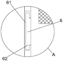
FIG. 2 is an enlarged view at A of FIG. 1;
FIG. 3 is a front cross-sectional view of the present invention;
FIG. 4 is an enlarged view at B of FIG. 3;
FIG. 5 is an enlarged view at C of FIG. 3;
FIG. 6 is a side view of the present invention;
FIG. 7 is an enlarged view at D of FIG. 6;
description of the main element symbols:
in the figure: 1. a fixed mount; 2. a low negative pressure aspirator; 21. a housing; 22. a low negative pressure aspirator body; 23. a first draft tube; 24. a timing switch; 25. a negative pressure regulator; 26. a second draft tube; 3. a drainage bottle; 31. a liquid outlet; 4. a waste liquid treatment device; 41. a waste liquid bag; 42. a connecting assembly; 421. a threaded sleeve; 422. an isolation film; 43. a puncture assembly; 431. puncturing needle; 432. a fixing plate; 433. a spring; 5. an alarm mechanism; 51. a guide bar; 52. an induction rod; 53. floating the ball; 54. an alarm; 55. a baffle plate; 6. a limiting component; 61. a card slot; 62. clamping the strip; 7. a pushing assembly; 71. an electric push rod; 72. buckling; 73. a limiting groove.
Detailed Description
To further illustrate the technical means and effects of the present invention adopted to achieve the predetermined objects, the following detailed description of the embodiments, structures, features and effects according to the present invention will be given with reference to the accompanying drawings and preferred embodiments.
Referring to fig. 1-7, the integrated low-negative-pressure abdominal drainage device comprises a fixing frame 1 and a low-negative-pressure aspirator 2 arranged on the fixing frame 1, wherein a plurality of drainage bottles 3 are connected below the low-negative-pressure aspirator 2, the plurality of drainage bottles 3 are all connected with a waste liquid treatment device 4, and the drainage bottles 3 and the waste liquid treatment device 4 are both movably connected with the fixing frame 1;
waste liquid treatment device 4 includes waste liquid bag 41, the bottom of drainage bottle 3 is provided with liquid outlet 31, waste liquid bag 41 passes through coupling assembling 42 and is connected with liquid outlet 31, be provided with puncture assembly 43 on the drainage bottle 3, in drainage bottle 3 and puncture assembly 43 and coupling assembling 42 swing joint were arranged in to the bottom one side of puncture assembly 43.
The low negative pressure aspirator 2 comprises a shell 21 arranged on the fixing frame 1 and a low negative pressure aspirator main body 22 arranged in the shell 21, the low negative pressure aspirator main body 22 is connected with a plurality of first drainage tubes 23, the connection parts of the first drainage tubes 23 and the low negative pressure aspirator main body 22 are provided with a timing switch 24, one end of each first drainage tube 23 far away from the low negative pressure aspirator main body 22 is connected with a negative pressure regulator 25, the negative pressure regulator 25 is further connected with a second drainage tube 26, and one end of each second drainage tube 26 far away from the negative pressure regulator 25 is movably connected with the drainage bottle 3.
In this embodiment, the third drainage tube connected to the abdominal drainage tube of the patient is connected to the drainage bottle 3, and the third drainage tube is not shown in the drawings. The negative pressure is generated in the drainage bottle 3 after the low negative pressure aspirator 2 is opened, blood, body fluid or secretion and the like in the abdominal cavity are drained into the drainage bottle 3 through the abdominal cavity drainage tube and the third drainage tube, the drainage bottle 3 is made of transparent materials, the color of the drainage liquid can be seen, and doctors are helped to judge the condition in the abdominal cavity. After drainage liquid in drainage bottle 3 reaches certain capacity, discharge drainage liquid through waste liquid treatment device 4 and collect and carry out preliminary disinfection, then wait for further processing, reduce the risk that takes place the infection when drainage liquid clearance.
Coupling assembling 42 and waste liquid bag 41 are disposable, the antiseptic solution is equipped with in the waste liquid bag 41, be provided with the isolation layer that supplies the puncture on the coupling assembling 42, under the initial condition, the isolation layer keeps apart drainage liquid in drainage bottle 3 and blocks, when drainage liquid need discharge, punctures the isolation layer through puncture assembly 43, drainage liquid flows into in waste liquid bag 41 and carries out preliminary disinfection, follow-up further processing as medical waste, it is safer.
During drainage, negative pressure is generated in the drainage bottle 3 through the low negative pressure aspirator main body 22, the time for starting negative pressure drainage and the time for single drainage can be set through the timing switch 24, and the size of the negative pressure can be adjusted through the negative pressure regulator 25.
One end of the second drainage tube 26 extending into the drainage bottle 3 is provided with a layer of air-permeable and water-impermeable membrane to prevent drainage liquid from being sucked back into the negative pressure suction apparatus 2.
Specifically, coupling assembling 42 includes thread bush 421 and barrier film 422 of setting in thread bush 421, the one end and the liquid outlet 31 threaded connection of thread bush 421, the other end and the waste liquid bag 41 of thread bush 421 are connected, piercing assembly 43 and barrier film 422 swing joint.
The puncture assembly 43 comprises a puncture needle 431 arranged in the drainage bottle 3, one side of the top end of the puncture needle 431 penetrates through the top wall of the drainage bottle 3 and is connected with a fixing plate 432, a spring 433 is sleeved on the outer side of the puncture needle 431, and two ends of the spring 433 are respectively fixed on the top of the drainage bottle 3 and the fixing plate 432.
In this embodiment, the waste liquid bag 41 is mounted on the liquid outlet 31 through the threaded sleeve 421, the drainage liquid is isolated through the isolation film 422, in an initial state, the bottom end side of the puncture needle 431 is positioned above the liquid outlet 31, when drainage liquid in the drainage bottle 3 needs to be discharged, the fixing plate 432 is pressed downwards until the isolation film 422 is punctured by the bottom end side of the puncture needle 431, at this time, the spring 433 is in a compressed state, and after the fixing plate 432 is loosened, the fixing plate 432 returns to an initial position under the elastic force of the spring 433.
After the drainage liquid is discharged once, the thread sleeve 421 is separated from the liquid outlet 31, and the thread sleeve 421 and the waste liquid bag 41 are replaced with new ones, and the waste liquid bag 41 filled with the drainage liquid is sealed by the top cover.
Specifically, the drainage bottle 3 is provided with an alarm mechanism 5.
In this embodiment, after drainage liquid in drainage bottle 3 reached appointed capacity, alarm mechanism 5 sent the warning, and suggestion medical personnel clear up, take place the backward flow after avoiding drainage liquid to be too full.
When the drainage device is used, the floating ball 53 rises along with the rising of the drainage liquid level, the alarm 54 gives an alarm when the floating ball 53 touches the induction rod 52, and the alarm 54 can be turned off once when medical personnel discharge drainage liquid. The floating ball 53 is always positioned between the induction rod 52 and the baffle 55, and the floating ball 53 is limited by the baffle 55, so that the floating ball 53 is prevented from being punctured by the puncture assembly 43.
Specifically, it is a plurality of through spacing subassembly 6 swing joint between the drainage bottle 3, it is a plurality of all connect through promotion subassembly 7 between drainage bottle 3 and the mount 1.
Spacing subassembly 6 includes draw-in groove 61 and with draw-in groove 61 assorted card strip 62, card strip 62 and draw-in groove 61 swing joint, it is a plurality of one side of drainage bottle 3 all is provided with draw-in groove 61, and is a plurality of the opposite side of drainage bottle 3 all is provided with card strip 62.
The pushing assembly 7 comprises an electric push rod 71 installed on the fixing frame 1 and a buckle 72 arranged at the output end of the electric push rod 71, a limit groove 73 matched with the buckle 72 is formed in the drainage bottle 3, the buckle 72 is movably connected with the limit groove 73, and the drainage bottle 3 is slidably connected with the fixing frame 1.
In this embodiment, can use one or more drainage bottle 3 according to actual conditions, the drainage bottle that marks in the attached figure is 3. Different drainage bottles 3 are connected through spacing subassembly 6, and convenient equipment is with spacing, through setting up promotion subassembly 7, not only conveniently removes appointed position with drainage bottle 3, also conveniently changes waste liquid treatment device 4.
When needing to install drainage bottle 3, in the draw-in groove 61 that will block strip 62 card and go into corresponding, insert drainage bottle 3 with bottom one side of second drainage tube 26 in, then block into corresponding buckle 72 in spacing groove 73, put into mount 1 with drainage bottle 3 and waste liquid bag 41 on, the output shrink of operation electric putter 71 stops when drainage bottle 3 and waste liquid bag 41 move the assigned position, adjusts the position of second drainage tube 26 at last.
When in use, the invention comprises the following steps:
s1: connecting the threaded sleeve 421 with the corresponding liquid outlet 31, clamping the clamping strip 62 into the corresponding clamping groove 61, inserting one side of the bottom end of the second drainage tube 26 into the drainage bottle 3, then clamping the corresponding buckle 72 into the limiting groove 73, placing the drainage bottle 3 and the waste liquid bag 41 onto the fixing frame 1, operating the output end of the electric push rod 71 to contract until the drainage bottle 3 and the waste liquid bag 41 move to the designated positions, and finally adjusting the position of the second drainage tube 26;
s2: connecting a third drainage tube connected with the wound to the drainage bottle 3, setting the time for starting negative pressure drainage and the time for single drainage through a timing switch 24, and setting the size of negative pressure through a negative pressure regulator 25;
s3: when the liquid in the drainage bottle 3 reaches the designated volume, the floating ball 53 rises along with the rising of the drainage liquid level, and when the floating ball 53 touches the induction rod 52, the alarm 54 gives an alarm;
s4: and (3) closing the alarm 54, pressing the fixing plate 432 downwards until one side of the bottom end of the puncture needle 431 punctures the isolating membrane 422, discharging the drainage liquid into the waste liquid bag 41 for preliminary disinfection, separating the thread sleeve 421 from the liquid outlet 31 after all the drainage liquid is discharged, replacing the thread sleeve 421 and the waste liquid bag 41 with new ones, and sealing the waste liquid bag 41 filled with the drainage liquid through a top cover.
Although the present invention has been described with reference to the preferred embodiments, it will be understood by those skilled in the art that various changes may be made and equivalents may be substituted for elements thereof without departing from the scope of the present invention.
Claims (9)
1. Integration low negative pressure abdominal cavity drainage device includes mount (1) and sets up low negative pressure aspirator (2) on mount (1), its characterized in that: a plurality of drainage bottles (3) are connected below the low negative pressure aspirator (2), a waste liquid treatment device (4) is connected to each of the plurality of drainage bottles (3), and the drainage bottles (3) and the waste liquid treatment device (4) are movably connected with the fixing frame (1);
waste liquid treatment device (4) include waste liquid bag (41), the bottom of drainage bottle (3) is provided with liquid outlet (31), waste liquid bag (41) are connected with liquid outlet (31) through coupling assembling (42), be provided with puncture assembly (43) on drainage bottle (3), in drainage bottle (3) and puncture assembly (43) and coupling assembling (42) swing joint are arranged in to the bottom one side of puncture assembly (43).
2. The integrated low negative pressure abdominal drainage device of claim 1, wherein: coupling assembling (42) include thread bush (421) and set up barrier film (422) in thread bush (421), the one end and liquid outlet (31) threaded connection of thread bush (421), the other end and the waste liquid bag (41) of thread bush (421) are connected, puncture subassembly (43) and barrier film (422) swing joint.
3. The integrated low negative pressure abdominal drainage device of claim 2, wherein: puncture component (43) is including setting up pjncture needle (431) in drainage bottle (3), the top one side of pjncture needle (431) is passed drainage bottle (3) roof and is connected with fixed plate (432), the outside cover of pjncture needle (431) is equipped with spring (433), the both ends of spring (433) are fixed respectively on drainage bottle (3) top and fixed plate (432).
4. The integrated low negative pressure abdominal drainage device of claim 1, wherein: the low negative pressure aspirator (2) is including setting up casing (21) on mount (1) and setting up low negative pressure aspirator main part (22) in casing (21), connect on low negative pressure aspirator main part (22) with a plurality of first drainage tube (23), a plurality of the junction of first drainage tube (23) and low negative pressure aspirator main part (22) all is provided with time switch (24), the one end that low negative pressure aspirator main part (22) were kept away from in first drainage tube (23) is connected with negative pressure regulator (25), still be connected with second drainage tube (26) on negative pressure regulator (25), the one end and drainage bottle (3) swing joint that negative pressure regulator (25) were kept away from in second drainage tube (26).
5. The integrated low negative pressure abdominal drainage device of claim 1, wherein: an alarm mechanism (5) is arranged on the drainage bottle (3).
6. The integrated low negative pressure abdominal drainage device of claim 5, wherein: alarm mechanism (5) are including fixing guide bar (51) in drainage bottle (3), be provided with response pole (52) and baffle (55) on guide bar (51), be provided with between response pole (52) and baffle (55) and float ball (53), float ball (53) and guide bar (51) swing joint, the front side of drainage bottle (3) is provided with alarm (54), alarm (54) and response pole (52) electric connection.
7. The integrated low negative pressure abdominal drainage device of claim 1, wherein: a plurality of drainage bottles (3) are movably connected through a limiting component (6), and a plurality of drainage bottles (3) are connected with the fixing frame (1) through a pushing component (7).
8. The integrated low negative pressure abdominal drainage device of claim 7, wherein: spacing subassembly (6) including draw-in groove (61) and with draw-in groove (61) assorted card strip (62), card strip (62) and draw-in groove (61) swing joint, it is a plurality of one side of drainage bottle (3) all is provided with draw-in groove (61), and is a plurality of the opposite side of drainage bottle (3) all is provided with card strip (62).
9. The integrated low negative pressure abdominal drainage device of claim 7, wherein: the pushing assembly (7) comprises an electric push rod (71) arranged on the fixing frame (1) and a buckle (72) arranged at the output end of the electric push rod (71), a limiting groove (73) matched with the buckle (72) is formed in the drainage bottle (3), the buckle (72) is movably connected with the limiting groove (73), and the drainage bottle (3) is connected with the fixing frame (1) in a sliding mode.
Priority Applications (1)
| Application Number | Priority Date | Filing Date | Title |
|---|---|---|---|
| CN202210770252.7A CN115006626B (en) | 2022-06-30 | 2022-06-30 | Integrated low negative pressure abdominal cavity drainage device |
Applications Claiming Priority (1)
| Application Number | Priority Date | Filing Date | Title |
|---|---|---|---|
| CN202210770252.7A CN115006626B (en) | 2022-06-30 | 2022-06-30 | Integrated low negative pressure abdominal cavity drainage device |
Publications (2)
| Publication Number | Publication Date |
|---|---|
| CN115006626A true CN115006626A (en) | 2022-09-06 |
| CN115006626B CN115006626B (en) | 2023-04-28 |
Family
ID=83078736
Family Applications (1)
| Application Number | Title | Priority Date | Filing Date |
|---|---|---|---|
| CN202210770252.7A Active CN115006626B (en) | 2022-06-30 | 2022-06-30 | Integrated low negative pressure abdominal cavity drainage device |
Country Status (1)
| Country | Link |
|---|---|
| CN (1) | CN115006626B (en) |
Cited By (1)
| Publication number | Priority date | Publication date | Assignee | Title |
|---|---|---|---|---|
| CN116440341A (en) * | 2023-05-19 | 2023-07-18 | 安能医疗器械(常熟)有限公司 | Negative pressure suction device |
Citations (7)
| Publication number | Priority date | Publication date | Assignee | Title |
|---|---|---|---|---|
| CN102069937A (en) * | 2010-11-25 | 2011-05-25 | 大连海洋大学 | Combined bath lotion bottle |
| CN204170266U (en) * | 2014-10-22 | 2015-02-25 | 天津市海河医院 | The automaton of indwelling catheter |
| CN205099779U (en) * | 2015-11-10 | 2016-03-23 | 苏州道蒙恩电子科技有限公司 | Online liquid -level monitoring device of plating bath |
| CN211357001U (en) * | 2019-08-16 | 2020-08-28 | 台州市立医院 | Hydrops draw-out device for tumor surgery |
| CN215929203U (en) * | 2021-10-19 | 2022-03-01 | 南昌大学第一附属医院 | Emergency oxygen charging device |
| CN216483441U (en) * | 2021-12-18 | 2022-05-10 | 安徽医科大学第二附属医院 | Intelligent weighing type drainage frame |
| CN114642776A (en) * | 2022-03-21 | 2022-06-21 | 安徽医科大学第二附属医院 | Intelligent flushing and low negative pressure drainage device for medical three-cavity drainage tube |
-
2022
- 2022-06-30 CN CN202210770252.7A patent/CN115006626B/en active Active
Patent Citations (7)
| Publication number | Priority date | Publication date | Assignee | Title |
|---|---|---|---|---|
| CN102069937A (en) * | 2010-11-25 | 2011-05-25 | 大连海洋大学 | Combined bath lotion bottle |
| CN204170266U (en) * | 2014-10-22 | 2015-02-25 | 天津市海河医院 | The automaton of indwelling catheter |
| CN205099779U (en) * | 2015-11-10 | 2016-03-23 | 苏州道蒙恩电子科技有限公司 | Online liquid -level monitoring device of plating bath |
| CN211357001U (en) * | 2019-08-16 | 2020-08-28 | 台州市立医院 | Hydrops draw-out device for tumor surgery |
| CN215929203U (en) * | 2021-10-19 | 2022-03-01 | 南昌大学第一附属医院 | Emergency oxygen charging device |
| CN216483441U (en) * | 2021-12-18 | 2022-05-10 | 安徽医科大学第二附属医院 | Intelligent weighing type drainage frame |
| CN114642776A (en) * | 2022-03-21 | 2022-06-21 | 安徽医科大学第二附属医院 | Intelligent flushing and low negative pressure drainage device for medical three-cavity drainage tube |
Cited By (2)
| Publication number | Priority date | Publication date | Assignee | Title |
|---|---|---|---|---|
| CN116440341A (en) * | 2023-05-19 | 2023-07-18 | 安能医疗器械(常熟)有限公司 | Negative pressure suction device |
| CN116440341B (en) * | 2023-05-19 | 2023-10-20 | 安能医疗器械(常熟)有限公司 | Negative pressure suction device |
Also Published As
| Publication number | Publication date |
|---|---|
| CN115006626B (en) | 2023-04-28 |
Similar Documents
| Publication | Publication Date | Title |
|---|---|---|
| HK1071527A1 (en) | High volume liquid waste collection and disposal system | |
| KR20050031983A (en) | Automatic urine disposal device | |
| DK1225930T4 (en) | Vacuum Bag Interior. | |
| CN116600750A (en) | Fluid delivery assemblies, systems, and methods | |
| CN115006626A (en) | Integrated low negative pressure abdominal cavity drainage device | |
| CN216294849U (en) | Medical device capable of conducting drainage and flushing | |
| JP2000202020A (en) | Medical suction apparatus | |
| CN210750554U (en) | Wound/incision leakage irrigation drainage device | |
| CN219185164U (en) | Sputum aspirator | |
| CN217907830U (en) | Urine bag subassembly convenient to gather urine sample | |
| CN213608702U (en) | Clinical drainage device of urological department | |
| CN218833266U (en) | Closed negative pressure drainage system | |
| CN217908331U (en) | Flushing device for ophthalmology | |
| CN213554224U (en) | Disposable integrated negative pressure suction machine | |
| CN219290265U (en) | Intelligent urine nursing instrument | |
| CN211675573U (en) | Drainage device for hepatobiliary surgery | |
| CN110522957A (en) | A kind of Intensive Care Therapy clinic effusion drainage device | |
| CN211485880U (en) | Effusion quantitative extraction device for incretion | |
| CN215134525U (en) | Intraoperative flushing fluid collecting barrel | |
| CN214343480U (en) | Medical sputum collection device | |
| CN215273841U (en) | Automatic washing unit of otology | |
| CN214435812U (en) | Disposable nasal cavity sterilization treatment device | |
| CN211912118U (en) | Automatic body fluid collecting and processing device for infected patient | |
| CN215504743U (en) | Stomach washer for internal medicine | |
| CN212756657U (en) | Hepatobiliary surgery hydrops collection device |
Legal Events
| Date | Code | Title | Description |
|---|---|---|---|
| PB01 | Publication | ||
| PB01 | Publication | ||
| SE01 | Entry into force of request for substantive examination | ||
| SE01 | Entry into force of request for substantive examination | ||
| GR01 | Patent grant | ||
| GR01 | Patent grant |