CN1149951A - Recording and reproduction of trick mode video signal - Google Patents
Recording and reproduction of trick mode video signal Download PDFInfo
- Publication number
- CN1149951A CN1149951A CN95193393A CN95193393A CN1149951A CN 1149951 A CN1149951 A CN 1149951A CN 95193393 A CN95193393 A CN 95193393A CN 95193393 A CN95193393 A CN 95193393A CN 1149951 A CN1149951 A CN 1149951A
- Authority
- CN
- China
- Prior art keywords
- track part
- track
- trick mode
- information
- hatching
- Prior art date
- Legal status (The legal status is an assumption and is not a legal conclusion. Google has not performed a legal analysis and makes no representation as to the accuracy of the status listed.)
- Pending
Links
Images


Classifications
-
- H—ELECTRICITY
- H04—ELECTRIC COMMUNICATION TECHNIQUE
- H04N—PICTORIAL COMMUNICATION, e.g. TELEVISION
- H04N5/00—Details of television systems
- H04N5/76—Television signal recording
- H04N5/78—Television signal recording using magnetic recording
- H04N5/782—Television signal recording using magnetic recording on tape
- H04N5/783—Adaptations for reproducing at a rate different from the recording rate
-
- H—ELECTRICITY
- H04—ELECTRIC COMMUNICATION TECHNIQUE
- H04N—PICTORIAL COMMUNICATION, e.g. TELEVISION
- H04N5/00—Details of television systems
- H04N5/76—Television signal recording
- H04N5/78—Television signal recording using magnetic recording
- H04N5/782—Television signal recording using magnetic recording on tape
- H04N5/7824—Television signal recording using magnetic recording on tape with rotating magnetic heads
- H04N5/7826—Television signal recording using magnetic recording on tape with rotating magnetic heads involving helical scanning of the magnetic tape
- H04N5/78263—Television signal recording using magnetic recording on tape with rotating magnetic heads involving helical scanning of the magnetic tape for recording on tracks inclined relative to the direction of movement of the tape
-
- H—ELECTRICITY
- H04—ELECTRIC COMMUNICATION TECHNIQUE
- H04N—PICTORIAL COMMUNICATION, e.g. TELEVISION
- H04N9/00—Details of colour television systems
- H04N9/79—Processing of colour television signals in connection with recording
- H04N9/80—Transformation of the television signal for recording, e.g. modulation, frequency changing; Inverse transformation for playback
- H04N9/804—Transformation of the television signal for recording, e.g. modulation, frequency changing; Inverse transformation for playback involving pulse code modulation of the colour picture signal components
- H04N9/8042—Transformation of the television signal for recording, e.g. modulation, frequency changing; Inverse transformation for playback involving pulse code modulation of the colour picture signal components involving data reduction
-
- H—ELECTRICITY
- H04—ELECTRIC COMMUNICATION TECHNIQUE
- H04N—PICTORIAL COMMUNICATION, e.g. TELEVISION
- H04N9/00—Details of colour television systems
- H04N9/79—Processing of colour television signals in connection with recording
- H04N9/80—Transformation of the television signal for recording, e.g. modulation, frequency changing; Inverse transformation for playback
- H04N9/82—Transformation of the television signal for recording, e.g. modulation, frequency changing; Inverse transformation for playback the individual colour picture signal components being recorded simultaneously only
- H04N9/8205—Transformation of the television signal for recording, e.g. modulation, frequency changing; Inverse transformation for playback the individual colour picture signal components being recorded simultaneously only involving the multiplexing of an additional signal and the colour video signal
- H04N9/8227—Transformation of the television signal for recording, e.g. modulation, frequency changing; Inverse transformation for playback the individual colour picture signal components being recorded simultaneously only involving the multiplexing of an additional signal and the colour video signal the additional signal being at least another television signal
Abstract
A recording arrangement is provided for recording trick mode information in portions of tracks. The recording arrangement has at least two recording heads (A, B). The trick mode information recorded in the portions in the tracks enable a trick mode during reproduction in a reproducing arrangement having reading means (50) for reading the trick mode information from the tracks, the reading means having at least a first and a second reading head (A, B) located at the circumference of a head drum such that the two heads are either located at e.g. 180 DEG on the head drum or form a head pair of two rigidly connected heads located side by side, the first and second heads of the reading means (50) having gaps with an azimuth angle which is substantially equal to the azimuth angle of the first and second write head respectively of the writing means, and where the transport speed of the record carrier (40) in the said trick mode being n times the nominal transport velocity during normal play reproduction where n is an integer and comprises a divisor number p larger than 1. The trick mode information is recorded in such a way that in a group of 2p tracks (T2 to T7) the trick mode information is recorded in a portion of a first (T2), second (T3) and a third track (T5) in said group of 2p tracks, the first and second tracks (T2, T3) being neighbouring tracks, the trick mode information stored in the portion (P1) of the first track (T2) being different from the trick mode information stored in the portion (P2) of the second track (T3), the trick mode information stored in the portion (P3) of the third track (T5) being equal to at least part of the trick mode information which is stored in the portion (P2) of one of the first and second tracks (T3).
Description
The present invention relates to be used on magnetic recording medium, the tape deck of recording digital video signals in the skewed track, this tape deck comprises:
-be used for the input of receiving digital video signal,
-be used for to this digital video signal carry out chnnel coding, obtaining to be suitable for recording the channel coding device of the channel signal in the track part on the described record carrier,
-be used for channel signal is write write device in the track part, this write device comprise be arranged on around the rotary head cylinder, at least the first and second different write heads of azimuth of head gap; Also relate to the record carrier that obtains with tape deck; And, relate to the regenerating unit that is used for from record carrier regeneration vision signal.
The tape deck that provides in that section of beginning is known in EP-A-492704, and this document is classified file (1) as in the list of references inventory at the application's book end.
Known devices is the tape deck of helical scan type, is used for respectively in the audio signal recording district of each bar order track part and video signal recording district included digital audio and video signals and digital video signal in the recording information signal.In this respect, with reference to the european patent application book No.93202950 that proposes in early time, i.e. document (2) in the list of references inventory, and No.93201263, i.e. document (3) in this document inventory.
The file of prior art relates to realizing the suggestion of new digital video cassette recorder (DVC) standard, and this standard allows digital video signal and digital audio and video signals recorded on the longitudinal magnetic recording carrier and be it is born again from the longitudinal magnetic recording carrier.This new digital VTR standard will produce so-called DVC type new digital VTR and regenerating unit.
The present invention aims to provide the tape deck that can write down other type information signal.More precisely, the present invention aims to provide a kind of like this information that will write down, and can realize one or more trick mode in making during regenerated signal from record carrier.Tape deck is characterised in that according to the present invention, and this tape deck also has: be used for drawing from digital video signal the trick mode information generator of trick mode video signal; Be adaptive to trick mode video signal and digital video signal are encoded so that obtain the channel coding device of compound channel signal at its output; Be adaptive to this compound channel signal is write write device in the track part, be used in having the regenerating unit of read apparatus, realizing the regeneration of trick mode, this read apparatus is used for reading the compound channel signal from track part, it has at least the first and second reading heads, these two magnetic heads are set on the head drum, make their position or be separated from each other a certain angle around the head drum, perhaps form two and couple together a pair of magnetic head that is provided with side by side securely, the azimuth of first and second head gaps of read apparatus equals the azimuth of first and second write heads in the write device substantially, in described trick mode the tape running speed of record carrier be specified tape running speed in the regeneration period of normal play n doubly, herein, n is an integer, and comprise factor P greater than 1, channel coding device is adaptive to such method trick mode video signal is encoded: make in one group of 2P bar track part, the trick mode video signal of having encoded is recorded in described one group of 2P bar track part first, second, in the part of the 3rd track part, article first and second, track part is adjacent track part, the trick mode information of encoding that is stored in that part of article one track part is different with the trick mode of coding information in being stored in that part of second track part, and the trick mode information of encoding in that part of the 3rd track part of being stored in equals to be stored in the message part of the interior trick mode of encoding at least of that part of one of article one and second track part.The present invention is based on such understanding: the information of trick mode should be recorded to realize on the record carrier of trick mode to regenerating unit with dissimilar scanner configurations.More precisely, the information of the trick mode that is write down should allow or have at least one pair of and be arranged on around the head drum with for example 180 ° of reading heads that separate or have at least two and couple together securely side by side and be arranged in the regenerating unit of a pair of magnetic head around the head drum, realize trick mode.According to the present invention, the partially filled information that trick mode is arranged of track part of at least three track parts in one group of 2P bar track part.
During with trick mode regeneration, around head drum, has in the device with for example 180 ° of two magnetic heads that separate the trick mode information of first magnetic head reading and recording in article one track part is that part of in this a pair of magnetic head; The trick mode information of second magnetic head reading and recording in this a pair of magnetic head at least the three track part is that part of as required, is gone back the trick mode information of reading and recording in another track part is that part of.
During with trick mode regeneration, around head drum, has in the device of at least one pair of magnetic head the trick mode information of first magnetic head reading and recording in article one track part is that part of in this a pair of magnetic head; The trick mode information of second magnetic head reading and recording in the second track part is that part of in this a pair of magnetic head.Because the information of reading from track part must be identical in both cases, so, being recorded in the trick mode information of second track part in that part of must be with to be stored in the trick mode information of the 3rd track part in that part of identical, and, if so, also must be identical with that part of interior information of described other track part.
When n was odd number, all that part all can be on the same position of each bar track part.If n is an even number, the 3rd position that track part is that part of will be on the track position different with that part of position of first and second track parts.
The feature of tape deck also is, for with equal in the normal play regeneration period specified tape running speed-n doubly, the tape running speed of record carrier in described second trick mode, realize the regeneration of second trick mode in described regenerating unit, the trick mode information generator also is adaptive to from digital video signal and draws second trick mode video signal; Channel coding device is adaptive to such method becomes second trick mode video signal of encoding to second trick mode video signal coding: in described one group of 2P bar track part, described second trick mode video signal of having encoded is recorded in described one group of 2P bar track part the 4th, the 5th, in the part of the 6th track part, article four and the 5th, track part is adjacent track part, the trick mode information of encoding that is stored in that part of the 4th track part is different with the trick mode of coding information in being stored in that part of the 5th track part, and the trick mode information of encoding in that part of the 6th track part of being stored in equals to be stored in the message part of that a part of interior trick mode of encoding at least of one of the 4th and the 5th track part.
For the speed of other trick mode, same methods produces trick mode information, and is stored in the each several part of each bar track part.
Be noted that in lists of documents, provided the file of the various prior arts of other method that realizes trick mode in relating between the record carrier reading duration, see file (7), (8) and (9) in this inventory.
Below, will illustrate above-mentioned and others of the present invention, thereby and these aspects be become clearly with reference to described embodiment when describing accompanying drawing.
Each illustrates a kind of scanner configurations of tape deck or regenerating unit among Fig. 1 a, Fig. 1 b and Fig. 1 c;
Fig. 2 a~2e illustrates the various track part configurations that are used for realizing the 2.Vn trick mode;
Fig. 3 a~3e illustrates and is used for realizing-the various track parts configurations of 2.Vn trick mode;
Fig. 4 a~4c illustrate be used for realizing the 2.Vn trick mode and-the various track parts configurations of 2.Vn trick mode;
Fig. 5 a~5e illustrates the various track part configurations that are used for realizing the 3.Vn trick mode;
Fig. 6 a and 6b illustrate and be used for realizing-the track part configuration of 3.Vn trick mode;
Fig. 7 a and 7b illustrate be used for realizing the 3.Vn trick mode and-the track part configuration of 3.Vn trick mode;
Fig. 8 a~8e illustrates the various track part configurations that are used for realizing the 4.Vn trick mode;
Fig. 9 a and 9b illustrate and be used for realizing-the track part configuration of 4.Vn trick mode;
Figure 10 a~10c illustrate be used for realizing the 4.Vn trick mode and-the various track parts configurations of 4.Vn trick mode;
Figure 11 illustrate be used for realizing the 5.Vn trick mode and-the track part configuration of 5.Vn trick mode;
Figure 12 a~12c illustrates the various track part configurations that are used for realizing the 6.Vn trick mode;
Figure 13 illustrates the track part configuration that is used for realizing the 9.Vn trick mode;
Figure 14 illustrates the track part configuration that is used for realizing the 27.Vn trick mode;
Figure 15 illustrates the track part configuration that is used for realizing 3.Vn, 9.Vn and 27.Vn trick mode;
Figure 16 is illustrated on the record carrier, in the track part, the position of trick mode information;
Figure 17 is illustrated in the MPEG video data stream sequence of I, a B and P frame;
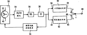
Figure 18 illustrates an embodiment of tape deck;
Figure 19 illustrates an embodiment of regenerating unit;
Figure 20 is illustrated in the form of track part on the record carrier;
Figure 21 is illustrated in the content of one of track part part in Figure 20 track part;
Figure 22 is illustrated in an embodiment of " special play-back " processing unit in Figure 18 tape deck;
Figure 23 illustrates and comprises the block content of " special play-back " information of error correction coding;
Figure 24 illustrates the another kind of error correction coding to this " special play-back " information; And
Figure 25 is illustrated in an embodiment of " special play-back " processing unit in Figure 19 regenerating unit.
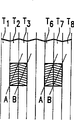
Fig. 1 a~1c illustrate be used for realizing " normal play " regeneration and " special play-back " regeneration, be used for tape deck and be used for three kinds of scanner configurations of regenerating unit.Fig. 1 a illustrates and has the scanner 1 that a pair of magnetic head, these two magnetic heads are designated as A and B, are provided with abreast and couple together securely, the head gap has different orientations.Fig. 1 b illustrates and has a pair of magnetic head that separates, these two magnetic heads be designated as A and B, head gap have different orientations, with 180 ° of angles be arranged on scanner 1 around the head drum '.Fig. 1 c illustrates and has two pairs of magnetic heads, and a pair of magnetic head is designated as A1, B1, and second pair of magnetic head is designated as A2, B2.Each is to azimuth, the gap difference of the magnetic head in the magnetic head.These two pairs of magnetic heads with 180 ° of angles be arranged on head drum around.
, be noted that the tape deck that has according to the scanner configurations of Fig. 1 a or 1b here, have identical head drum rotating speed.Have the tape deck according to the scanner configurations of Fig. 1 c, the rotating speed of its head drum is an above-mentioned rotating speed half.With same method, have regenerating unit according to the scanner configurations of one of Fig. 1 a or 1b, its rotating speed is identical with the tape deck that has same scanner configurations.Have regenerating unit according to the scanner configurations of Fig. 1 c and have this rotating speed half.
Be noted that other possible scanner configurations in addition, for example, four are separated 90 ° of angles and are arranged on head drum magnetic head on every side; With 180 ° of angles, two magnetic heads that be provided with, that the azimuth is identical.Perhaps, have two pairs of scanner configurations with upper magnetic head.
Fig. 2 a illustrates, and in trick mode, how the magnetic head A of scanner configurations and B scan track part among Fig. 1 a, herein, the speed of record carrier for example is the twice of forward, normal speed Vn, and wherein, Vn is the speed of the interior record carrier of the regeneration period of normal play mode.Fig. 2 a illustrates some track parts among T1~T8, herein, the track part of odd-numbered has with one of magnetic head A and B, promptly to have the magnetic head of a certain azimuthal head gap, the video information that writes down on track part, the track part of even-numbered have the video information that writes down with the magnetic head with another azimuthal head gap on this track part., suppose that magnetic head A reads the video information in the even-numbered track part here, magnetic head B reads the video information that writes down in the odd-numbered track part.
In the trick mode of twice Vn, track part shown in a pair of magnetic head scans by the path-line that is designated as A and B.Magnetic head A reads each information to record in the hatching part among track part T2, T3 and T6, the T7, and herein, magnetic head A reads in the information of hatching partial memory storage among track part T2 and the T6, and magnetic head B reads in the information of hatching partial memory storage among track part T3 and the T7.
Here, be noted that if tape deck has the scanner configurations according to Fig. 1 c, identical track part path then will appear, herein, a pair of magnetic head A1, B1 stride across the path of track part T2, T3 with scanning, and another strides across scanning to magnetic head A2, B2 the path of track part T6, T7.
Be noted that Fig. 2 a provides such impression here: these track parts are in the length direction that strictly is transverse to record carrier.But reality is not like this.They obliquely stride across record carrier.Therefore, between track part T1, T2 and track part T7, T8, though those parts be on the sustained height of track part,, they will have slight displacement on the direction of track part length.
Fig. 2 b illustrates, and in trick mode, how the magnetic head A of scanner configurations and B scan track part among Fig. 1 b, and herein, the speed of record carrier is the twice of normal speed Vn.Fig. 2 b illustrate with Fig. 2 a in the track part T1~T8 of identical number.Still supposition, magnetic head A reads the video information in the even-numbered track part, and magnetic head B reads the video information that writes down in the odd-numbered track part.
In the trick mode of twice Vn, the track part shown in magnetic head A and B scanning pattern line A and the B.Magnetic head B reads the information of the interior record of hatching part among track part T3 and the T7.Magnetic head A is in line sweep record carrier between two lines that are designated as B among Fig. 2 b, that be designated as A along strictness.Magnetic head A can not be from track part T5 read message because the azimuth of magnetic head A is not right for read message from track part T5.Magnetic head A can the information of reading and recording in track part T4 and T6, and can read the information of hatching partial memory storage in track part T4 and T6, and the part of hatching is not on the sustained height (or same position) among the part of these hatchings and track part T3 and the T7.
If require when head drum rotates a circle scanning record carrier, to read identical information from record carrier under the situation of Fig. 2 a and 2b, then following saying can be set up.The content of hatching part can be identical with hatching part in the track part T3 among Fig. 2 b in the track part T3 among Fig. 2 a, so the content of the interior hatching part of track part T7 is identical with the interior hatching part of track part T7 among Fig. 2 b among Fig. 2 a.About the content of hatching part in track part T4 and the T6 among hatching part and Fig. 2 b in the track part T6 among Fig. 2 a, following saying can be set up.The content of hatching part can be identical (in the case with the hatching part of track part T4 among Fig. 2 b in the track part T6 among Fig. 2 a, the interior hatching part of track part T6 does not need among Fig. 2 b, perhaps, can be used to store therein out of Memory), perhaps, with Fig. 2 b in the track part T6 hatching part identical (in the case, among Fig. 2 b in the track part T4 hatching part do not need, perhaps, can be used to store therein out of Memory).In other words,, can be taken as half to the length of hatching part in track part T4 and the T6 among Fig. 2 b as an example, those two parts comprise altogether with Fig. 2 a in the track part T6 hatching part institute canned data identical.
Fig. 2 c illustrates except hatching among track part T2 that utilizes magnetic head A to read and the T6 partly being taken as a kind of benchmark, in fact identical with Fig. 2 b situation.Now, magnetic head B is in line sweep record carrier between two lines that are designated as A among Fig. 2 c, that be designated as B along strictness.Magnetic head B can not read information from track part T4, because the azimuth of magnetic head B is not right for read message from track part T4.Magnetic head B can read in the information that writes down among track part T3 and the T5, can read in the information of the storage of hatching partial memory among track part T3 and the T5, and the part of hatching is not on the sustained height (or same position) among the part of these hatchings and track part T2 and the T6.
If require when head drum rotates a circle scanning record carrier, to read identical information from record carrier under the situation of Fig. 2 a and 2c, then following saying can be set up.The content of hatching part can be identical with hatching part in the track part T2 among Fig. 2 c in the track part T2 among Fig. 2 a, so, the content of hatching part, identical in the track part T6 among Fig. 2 a with the interior hatching part of track part T6 among Fig. 2 c.Now, about hatching content partly in track part T3 in the track part T3 among Fig. 2 a and among Fig. 2 c and the T5, following saying can be set up.The content of hatching part can be identical (in the case with the hatching part of track part T3 among Fig. 2 c in the track part T3 among Fig. 2 a, the hatching part does not need in the track part T5, perhaps, can be used to store therein out of Memory), it is perhaps, identical with hatching part in the track part T5 that (in the case, the hatching part does not need in the track part T3, perhaps, can be used to store therein out of Memory).In other words,, can be taken as half to the length of hatching part in track part T3 and the T5 among Fig. 2 c as an example, those two parts comprise altogether with Fig. 2 a in the track part T3 hatching part institute canned data identical.
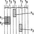
Can combine the situation of Fig. 2 a and 2b, so that to having Fig. 1 a scanner configurations, or the regenerating unit of Fig. 1 b scanner configurations or Fig. 1 c scanner configurations allows the trick mode of twice Vn.This has formed the track part form shown in Fig. 2 d.In one group of four track part that are designated as T4~T7, among track part T6 and the T7 among hatching part P1 and P2 and Fig. 2 a in track part T6 and the T7 shown in the hatching part identical, hatching part P3 and P4 are respectively corresponding to the hatching part shown in respectively in track part T6 and the T4 among Fig. 2 b among track part T6 and the T7.
Like this, about the saying of hatching part in track part T4 and the T6 among Fig. 2 b, effective too in early time for hatching part P3 and P4 among Fig. 2 d.That is: the content of hatching part P1 in the track part T6, can be identical (in the case with hatching part P3 in the track part T6, hatching part P4 does not need in the track part T4, perhaps, can be used to store therein out of Memory), it is perhaps, identical with hatching part P4 in the track part T4 that (in the case, hatching part P3 does not need in the track part T6, perhaps, can be used to store therein out of Memory).In other words, as an example, can be taken as half to the length of hatching part P3 and P4 in track part T6 and the T4 among Fig. 2 d, it is identical with hatching part P1 institute canned data in the track part T6 that those two parts comprise altogether.Respectively organize four track parts for adjacent, in those groups, occur on the identical position with group shown in Fig. 2 d in same track part form entirely, the information that is used for storing trick mode like this, can realize the regeneration of trick mode when tape running speed is twice Vn.
It should still be noted that, the each several part that is provided with in a track part (for example, part P1 in Fig. 2 d in the track part T6 and P3) do not need (for example directly to couple together mutually, do not need under the situation long like that shown in the image pattern 2d at each several part) because " special play-back " amount of information that will store in track part seldom requires very long part.Therefore, the gap may occur between those parts, these gaps may be used for storage " normal play " information and (promptly be used for realizing the information of " normal play " regeneration).And, can be placed on the part P4 among the track part T4 on the position lower in this track part.
Select as the another kind that the situation of Fig. 2 a and 2b is combined, can combine the situation of Fig. 2 a and 2c, so that the regenerating unit with Fig. 1 a scanner configurations or Fig. 1 b scanner configurations or Fig. 1 c scanner configurations is allowed the trick mode of twice Vn.This has formed the track part form shown in Fig. 2 e.In one group of four track part that are designated as T2~T5, among track part T2 and the T5 among hatching part P1 and P2 and Fig. 2 a in track part T2 and the T3 shown in the hatching part identical, hatching part P3 and P4 are corresponding to the hatching part shown in track part T3 and the T5 among Fig. 2 c among track part T5 and the T3.Like this, about the saying of hatching part in track part T3 and the T5 among Fig. 2 c, effective too in early time for hatching part P3 and P4 among Fig. 2 e.That is: the content of hatching part P2 is identical (in the case with hatching part P3 in the track part T5 in the track part T3, hatching part P4 does not need in the track part T3, perhaps, can be used to store therein out of Memory), it is perhaps, identical with hatching part P4 in the track part T3 that (in the case, hatching part P3 does not need in the track part T5, perhaps, can be used to store therein out of Memory).In other words, as an example, can be taken as half to the length of hatching part P3 and P4 in track part T5 and the T3 among Fig. 2 d respectively, it is identical with hatching part P2 institute canned data in the track part T3 that those two parts comprise altogether.Respectively organize four track parts for adjacent, in those groups, occur on the identical position with group shown in Fig. 2 e in identical track part form, the information that is used for storing trick mode is so that the regeneration of realization trick mode when tape running speed is twice Vn.And, above with reference to figure 2d for the saying of each several part position in each bar track part that is, those parts might not need to be connected with each other but can gapped saying between them, are general available, like this, here, equally also can use.
Fig. 3 a illustrates, and in trick mode, how magnetic head is to the scanning track part for the magnetic head A of scanner configurations and B among Fig. 1 a, herein, the speed of record carrier is twice reverse, normal speed Vn, and herein, Vn is the speed of record carrier in the regeneration period of normal play mode.Fig. 3 a illustrates track part T1~T8 with the method identical with Fig. 2 a.
In the trick mode of reverse twice Vn (otherwise, be called-2 times of Vn trick modes), magnetic head is designated as track part shown in A and the B to scanning with path-line.Magnetic head A reads each information to record in the hatching part among track part T2, T3 and T6, the T7, and herein, magnetic head A reads in the information of hatching partial memory storage among track part T2 and the T4, and magnetic head B reads in the information of hatching partial memory storage among track part T3 and the T7.
Here, should also be noted that if tape deck has the scanner configurations according to Fig. 1 c, identical track part path then will appear, herein, a pair of magnetic head A1, B1 stride across the path of track part T2, T3 with scanning, and a pair of magnetic head A2, B2 stride across scanning in the path of track part T6, T7.
Fig. 3 b illustrates, and in trick mode, how the magnetic head A of scanner configurations and B scan track part among Fig. 1 b, and herein, the speed of record carrier is-2 times of normal speed Vn.Fig. 3 b illustrate with Fig. 3 a in the track part T1~T8 of identical number.
In the trick mode of-2 times of Vn, magnetic head A and B scanning are designated as the track part shown in path-line A and the B.Magnetic head B reads the information that writes down in the hatching part among track part T3 and the T7.Magnetic head A is in line sweep record carrier between two lines that are designated as B among Fig. 3 b, that be designated as A along strictness.Magnetic head A can not read information from track part T5, because the azimuth of magnetic head A is not right for read message from track part T5.Magnetic head A can read in the information that writes down among track part T4 and the T6, can read the information of in track part T4 and T6 hatching partial memory storage, and the part of hatching is not on the sustained height (or same position) among the part of these hatchings and track part T3 and the T7.
If require under the situation of Fig. 3 a and 3b, when head drum rotates a circle scanning record carrier, read identical information from record carrier, then following saying can be set up.The content of hatching part in the track part T3 among Fig. 3 a, can be identical with hatching part in the track part T3 among Fig. 3 b, so, among Fig. 3 a in the track part T7 content of hatching part identical with the interior hatching part of track part T7 among Fig. 3 b.Now, about hatching content partly in track part T4 in the track part T6 among Fig. 3 a and among Fig. 3 b and the T6, following saying can be set up.The content of hatching part in the track part T6 among Fig. 3 a, can be identical (in the case with the hatching part of track part T4 among Fig. 3 b, the interior hatching part of track part T6 does not need among Fig. 3 b, perhaps, can be used to store therein out of Memory), perhaps, with Fig. 3 b in the track part T6 hatching part identical (in the case, the hatching part does not need in the track part T4, perhaps, can be used to store therein out of Memory).In other words,, can be taken as half to the length of hatching part in track part T4 and the T6 among Fig. 3 b as an example, those two parts comprise altogether with Fig. 3 a in the track part T6 hatching part institute canned data identical.
Situation shown in Fig. 3 c is except partly being taken as hatching among track part T2 that utilizes magnetic head A to read and the T6 a kind of benchmark, and in fact the situation with Fig. 3 b is identical.Now, magnetic head B is in line sweep record carrier between two lines that are designated as A among Fig. 3 c, that be designated as B along strictness.Magnetic head B can not read information from track part T4, because the azimuth of magnetic head B is not right for the information that reads from track part T4.Magnetic head B can read the information that writes down in track part T3 and T5, can read the information of hatching partial memory storage in track part T3 and T5, and the part of hatching is not on the sustained height (or same position) among the part of these hatchings and track part T2 and the T6.
If require when head drum rotates a circle scanning record carrier, to read identical information from record carrier under the situation of Fig. 3 a and 3c, then following saying can be set up.The content of hatching part can be identical with hatching part in the track part T2 among Fig. 3 c in the track part T2 among Fig. 3 a, and, the content of the interior hatching part of track part T6 is identical with the interior hatching part of track part T6 among Fig. 3 c among Fig. 3 a.About hatching content partly in track part T3 in the track part T3 among Fig. 3 a and among Fig. 3 c and the T5, following saying can be set up.The content of hatching part can be identical (in the case with the hatching part of track part T3 among Fig. 3 c in the track part T3 among Fig. 3 a, the interior hatching part of track part T5 does not need among Fig. 3 c, perhaps, can be used to store therein out of Memory), perhaps, with Fig. 3 c in the track part T5 hatching part identical (in the case, the hatching part does not need in the track part T3, perhaps, can be used to store therein out of Memory).In other words,, can be taken as half to the length of hatching part in track part T3 and the T5 among Fig. 3 c as an example, those two parts comprise altogether with Fig. 3 a in the track part T3 hatching part institute canned data identical.
Can combine the situation of Fig. 3 a and 3b, so that the regenerating unit with Fig. 1 a scanner configurations or Fig. 1 b scanner configurations or Fig. 1 c scanner configurations is allowed the trick mode of-2 times of Vn.This has formed the track part form shown in Fig. 3 d.In one group of four track part that are designated as T4~T7, among track part T6 and the T7 among hatching part P1 and P2 and Fig. 3 a in track part T6 and the T7 shown in the hatching part identical, hatching part P3 and P4 are respectively corresponding to the hatching part shown in track part T6 and the T4 among Fig. 3 b among track part T6 and the T4.Like this, about the saying of hatching part in track part T4 and the T6 among Fig. 3 b, effective too in early time for hatching part P3 and P4 among Fig. 3 d.
Respectively organize four track parts for adjacent, in those groups, occur on the identical position with group shown in Fig. 3 d in identical track part form, the information that is used for storing trick mode is so that the regeneration of realization trick mode when walking tape speed and be-2 times of Vn.
Here, about+n.Vn trick mode and-the n.Vn trick mode, more precisely,, should make general comment about just describing-structure shown in Fig. 2 e of the structure shown in Fig. 3 d of 2.Vn trick mode and+2.Vn trick mode.When comparison diagram 2e and 3d, these two kinds of structures that semble are the mirror symmetry.This is in order to illustrate, and for simplicity, just they are the mirror symmetry.Yet in fact, they are not to be the mirror symmetry, because track part is the inclined operation on record carrier; Magnetic head stride across record carrier with+n.Vn trick mode and-operation of n.Vn trick mode, so, be not the minute surface symmetry for the straight line of the transversal record carrier of strictness.The result is, among Fig. 2 e in the track part T5 among the position of part P3 and Fig. 3 d position of the interior part P4 of track part T4 with different.By the same token, among Fig. 2 d in the track part T3 among the position of part P4 and Fig. 3 d position of the interior part P3 of track part T6 also see the description of Fig. 4 a~4c with different.Because with above-mentioned same, these two parts of P1-and P2-are relative mutually on the length direction of track part also will to have slight displacement.
Select as the another kind that Fig. 3 a and 3b are combined, can combine the situation of Fig. 3 a and Fig. 3 c, so that the regenerating unit with Fig. 1 a scanner configurations or Fig. 1 b scanner configurations or Fig. 1 c scanner configurations is allowed the trick mode of-2 times of Vn.This has formed the track part form shown in Fig. 3 e.In one group of four track part that are designated as T2~T5, among track part T2 and the T5 among hatching part P1 and P2 and Fig. 3 a in track part T2 and the T3 shown in the hatching part identical, hatching part P3 and P4 are corresponding to the hatching part shown in track part T5 and the T3 among Fig. 3 c among track part T5 and the T3.Like this, about the saying of hatching part in track part T3 and the T5 among Fig. 3 c, effective too in early time for hatching part P3 and P4 among Fig. 3 e.Respectively organize four track parts for adjacent, in those groups, occur on the identical position with group shown in Fig. 3 e in identical track part form, the information that is used for storing trick mode is so that the regeneration of realization trick mode when tape running speed is-2 times of Vn.
Fig. 4 a illustrates Fig. 2 d and 3e format combination, so that realize two kinds of trick modes, that is: and 2 times of Vn trick modes and-2 times of Vn trick modes.Fig. 4 a also illustrates one group of four track part Ta~Td.The each several part that is designated as P1+~P4+ is respectively corresponding to part P1~P4 shown in Fig. 2 d, and the each several part that is designated as P1~P4-is respectively corresponding to part P1~P4 shown in Fig. 3 e.Respectively organize four track parts for adjacent, in those groups, occur on the identical position with group shown in Fig. 4 a in identical track part form, the information that is used for storing trick mode is so that be the regeneration of+2 trick modes of realization during with-2 times of Vn in tape running speed.
Before illustrate, for+n.Vn trick mode and-the n.Vn trick mode, the position difference of each several part in each bar track part.The result is that part P1-, P2-and P1+, P2+ do not need to be on the equal height of track part.And, suppose that part P1-, P2-are on the identical height in each bar track part substantially with P1+, P2+, distance in track part Tb between part P2-and the P4-, will and in track part Tc the distance between part P1+ and the P3+ different, the distance in track part Ta between part P1-and the P4+, will and in track part Td the distance between part P2+ and the P3-different.For whole other combinations with-n.Vn trick mode structure of+n.Vn trick mode structure, identical or suitable reasoning will be effective.
Fig. 4 b illustrates Fig. 2 e and 3d format combination, so that realize two kinds of trick modes, that is: and 2 times of Vn trick modes and-2 times of Vn trick modes.Fig. 4 b also illustrates one group of four track part Ta~Td.The each several part that is designated as P1+~P4+ is respectively corresponding to part P1-P4 shown in Fig. 2 e, and the each several part that is designated as P1-~P4-is respectively corresponding to part P1~P4 shown in Fig. 3 d.Respectively organize four track parts for adjacent, in those groups, occur on the identical position with group shown in Fig. 4 b in identical track part form, the information that is used for storing trick mode is so that be the regeneration of+2 trick modes of realization during with-2 times of Vn in tape running speed.
Fig. 4 c illustrates Fig. 2 d and 3d format combination, so that realize two kinds of trick modes, that is: and 2 times of Vn trick modes and-2 times of Vn trick modes.Fig. 4 c also illustrates one group of four track part Ta~Td.The each several part that is designated as P1+~P4+ is respectively corresponding to part P1~P4 shown in Fig. 2 d, and the each several part that is designated as P1-~P4-is respectively corresponding to part P1~P4 shown in Fig. 3 d.Respectively organize four track parts for adjacent, in those groups, occur on the identical position with group shown in Fig. 4 b in identical track part form, the information that is used for storing trick mode is so that be the regeneration of+2 trick modes of realization during with-2 times of Vn in tape running speed.The difference of Fig. 4 a and 4b form is that the trick mode information in part P1+ and P2+, part P1-and P2-is not on the sustained height (same position) in track part.
Obviously, when the format combination of Fig. 2 e and 3e is got up, just can obtain the 4th kind of form.
And, be noted that shown in Fig. 4 a~4c, in four track parts of each group, the information content of part P1+ and P1-, can equate mutually with the information content of part P2-and P2+.
Now, Fig. 5 a illustrates, and in trick mode, how the magnetic head A of scanner configurations and B scan track part among Fig. 1 a, and herein, the speed of record carrier is for example forward, three times of normal speed Vn.
In the trick mode of 3 times of Vn, a pair of head scanning be designated as path-line A and B, shown in track part.Magnetic head A reads each information to record in the hatching part among track part T2, T3 and T8, the T9, and herein, magnetic head A reads in the information of hatching partial memory storage among track part T2 and the T8, and magnetic head B reads in the information of hatching partial memory storage among track part T3 and the T9.
Here, be noted that if tape deck has the scanner configurations according to Fig. 1 c, identical track part path then will appear, herein, magnetic head strides across the path of track part T2, T3 to A1, B1 with scanning, and magnetic head strides across scanning to A2, B2 the path of track part T8, T9.
Fig. 5 b illustrates, and in trick mode, how the magnetic head A of scanner configurations and B scan track part among Fig. 1 b, and herein, the speed of record carrier is 3 times of normal speed Vn.Fig. 5 b illustrate with Fig. 5 a in the track part T1~T9 of identical number.
In the trick mode of 3 times of Vn, magnetic head A and B scanning are called the track part shown in path-line A and the B.Magnetic head B reads the information that writes down in the hatching part among track part T3 and the T9.Magnetic head A is in the line sweep record carrier that is designated as A between two lines that are designated as B among Fig. 5 b along strictness.Magnetic head A can the part of hatching read information from track part T6, because the azimuth of magnetic head A is correct for read message from track part T6.
If require when head drum rotates a circle scanning record carrier, to read identical information from record carrier under the situation of Fig. 5 a and 5b, then following saying can be set up.The content of hatching part can be identical with hatching part in the track part T3 among Fig. 5 b in the track part T3 among Fig. 5 a, so the content of the interior hatching part of track part T9 is identical with the interior hatching part of track part T9 among Fig. 5 b among Fig. 5 a.About the content of hatching part in the track part T6 among hatching part and Fig. 5 b in the track part T8 among Fig. 5 a, we can say that their content is identical.
Situation shown in Fig. 5 c, except hatching among track part T2 that utilizes magnetic head A to read and the T8 partly being taken as a kind of benchmark, in fact the situation with Fig. 5 b is identical.Now, magnetic head B is in the line sweep record carrier that is designated as B between two lines that are designated as A among Fig. 5 c along strictness.Magnetic head B can read information from track part T5, because the azimuth of magnetic head B is correct for read information from track part T5.
If require when head drum rotates a circle scanning record carrier, to read identical information from record carrier under the situation of Fig. 5 a and 5c, then following saying can be set up.The content of hatching part can be identical with hatching part in the track part T2 among Fig. 5 c in the track part T2 among Fig. 5 a, so the content of the interior hatching part of track part T8 is identical with the interior hatching part of track part T8 among Fig. 5 c among Fig. 5 a.Now, about the content of hatching part in the track part T5 among hatching part and Fig. 5 c in the track part T3 among Fig. 5 a, following saying can be set up.The content of the interior hatching part of track part T3 is identical with the hatching part of track part T5 among Fig. 5 c among Fig. 5 a.
Can combine the situation of Fig. 5 a and 5b, so that the regenerating unit with Fig. 1 a scanner configurations or Fig. 1 b scanner configurations or Fig. 1 c scanner configurations is allowed the trick mode of 3 times of Vn.This has formed the track part form shown in Fig. 5 d.In one group of six track part that are designated as T4-T9, among track part T8 and the T9 among hatching part P1 and P2 and Fig. 5 a in track part T8 and the T9 shown in the hatching part identical, hatching part P3 is corresponding to the hatching part shown in the track part T6 among Fig. 5 b among the track part T6.
Like this, about the saying of hatching part in the track part T6 among Fig. 5 b, effective too in early time for hatching part T3 among Fig. 5 d.That is: the content of hatching part P1 is identical with hatching part P3 in the track part T6 in the track part T3.Respectively organize six track parts for adjacent, in those groups, occur on the identical position with group shown in Fig. 5 d in identical track part form, the information that is used for storing trick mode is so that the regeneration of realization trick mode when tape running speed is 3 times of Vn.
In other words, can combine the situation of Fig. 5 a and Fig. 5 c, so that the regenerating unit with Fig. 1 a scanner configurations or Fig. 1 b scanner configurations or Fig. 1 c scanner configurations is allowed the trick mode of 3 times of Vn.This has formed the track part form shown in Fig. 5 e.In one group of six track part that are designated as T2~T7, among track part T2 and the T3 among hatching part P1 and P2 and Fig. 5 a in track part T2 and the T3 shown in the hatching part identical, hatching part P3 is corresponding to the hatching part shown in the track part T5 among Fig. 5 c among the track part T5.Like this, about the saying of hatching part in the track part T5 among Fig. 5 c, effective too in early time for hatching part P3 among Fig. 5 e.That is: the content of hatching part P2, identical in the track part T3 with the interior hatching part P3 of track part T5.Respectively organize six track parts for adjacent, in those groups, occur on the identical position with group shown in Fig. 5 e in identical track part form, the information that is used for storing trick mode is so that the regeneration of realization trick mode when tape running speed is 3 times of Vn.
For the trick mode of-3 times of Vn, can carry out with reference to figure 3 for-2 times of identical practices that the Vn trick mode is performed.The results are shown in Fig. 6 a and 6b.
For the regenerating unit with Fig. 1 a scanner configurations or Fig. 1 b scanner configurations or Fig. 1 c scanner configurations being allowed-3 times trick mode, can utilize the track part form shown in Fig. 6 a, in one group of six track part that are designated as T4~T7, among track part T8 and the T9 among hatching part P1 and P2 and Fig. 5 a in track part T8 and the T9 shown in the hatching part identical, the content of hatching part P3 is identical with hatching part P1 among the track part T8 among the track part T6.Respectively organize six track parts for adjacent, in those groups, occur on the identical position with group shown in Fig. 6 a in identical track part form, the information that is used for storing trick mode is so that the regeneration of realization trick mode when tape running speed is-3 times of Vn.
When respectively organizing six track parts shown in comparison diagram 5d and the 6a, apparent, these two groups is identical.
In other words, can obtain the track part form of Fig. 6 b, so that the regenerating unit with Fig. 1 a scanner configurations or Fig. 1 b scanner configurations or Fig. 1 c scanner configurations is allowed the trick mode of-3 times of Vn.In one group of six track part that are designated as T2~T7, among track part T2 and the T3 among hatching part P1 and P2 and Fig. 5 a in track part T2 and the T3 shown in the hatching part identical, the content of hatching part P3 is identical with the interior part P2 of track part T3 among the track part T5.Respectively organize six track parts for adjacent, in those groups, occur on the identical position with group shown in Fig. 6 b in identical track part form, the information that is used for storing trick mode is so that the regeneration of realization trick mode when tape running speed is-3 times of Vn.When respectively organizing six track parts shown in comparison diagram 5d and the 6b, can also say that these two groups is identical.
Fig. 7 a illustrates Fig. 5 d and 6b format combination, so that realize two kinds of trick modes, that is: and 3 times of Vn trick modes and-3 times of Vn trick modes.Fig. 7 a also illustrates one group of six track part Ta~Tf.The each several part that is designated as P1+~p3+ is respectively corresponding to part P1~P3 shown in Fig. 5 d, and the each several part that is designated as P1-~P3-is respectively corresponding to part P1~P3 shown in Fig. 6 b.Respectively organize six track parts for adjacent, in those groups, occur on the identical position with group shown in Fig. 7 a in identical track part form, the information that is used for storing trick mode is so that be the regeneration of+3 trick modes of realization during with-3 times of Vn in tape running speed.
Fig. 7 b illustrates Fig. 5 e and 6a format combination, so that realize two kinds of trick modes, that is: and 3 times of Vn trick modes and-3 times of Vn trick modes.Fig. 7 b also illustrates one group of six track part Ta~Tf.The each several part that is designated as P1+~P3+ is respectively corresponding to part P1~P3 shown in Fig. 5 e, and the each several part that is designated as P1~P3-is respectively corresponding to part P1~P3 shown in Fig. 6 a.Respectively organize six track parts for adjacent, in those groups, occur on the identical position with group shown in Fig. 7 b in identical track part form, the information that is used for storing trick mode is so that be the regeneration of+3 trick modes of realization during with-3 times of Vn in tape running speed.
Obviously, also will get up the form of Fig. 5 a and 6a or the format combination of Fig. 5 e and 6b.In this case, the each several part of forward trick mode and reverse trick mode is not in each bar track part on the same position.
Fig. 8 a illustrates, and in trick mode, how the magnetic head A of scanner configurations and B scan track part among Fig. 1 a, herein, the speed of record carrier for example is forward, normal speed Vn four times, and herein, Vn is the speed of record carrier in the regeneration period of normal play mode.
In the trick mode of four times of Vn, a pair of head scanning is designated as the track part shown in path-line A and the B.Magnetic head A reads each information to record in the hatching part among track part T2, T3 and T10, the T11.Herein, magnetic head A reads in the information of hatching partial memory storage among track part T2 and the T10, and magnetic head B reads in the information of hatching partial memory storage among track part T3 and the T11.
Here, be noted that if tape deck has the scanner configurations according to Fig. 1 c, identical track part path then will appear, herein, a pair of magnetic head A1, B1 stride across the path of track part T2, T3 with scanning, and a pair of magnetic head A2, B2 stride across scanning in the path of track part T10, T11.
Fig. 8 b illustrates, and in trick mode, how the magnetic head A of scanner configurations and B scan track part among Fig. 1 b, and herein, the speed of record carrier is four times of normal speed Vn.Fig. 8 b illustrate with Fig. 8 a in identical track part.
In the trick mode of four times of Vn, magnetic head A and B scanning be designated as path-line A and B, shown in track part.Magnetic head B reads the information of the interior record of hatching part among track part T3 and the T11.Magnetic head A is in line sweep record carrier between two lines that are designated as B among Fig. 8 b, that be designated as A along strictness.Magnetic head A can not read information from track part T7, because the azimuth of magnetic head A is not right for the information that reads from track part T7.Magnetic head A can read the information that writes down in track part T6 and T8, can read in the information of hatching partial memory storage among track part T6 and the T8, and the part of hatching is not on the sustained height (or same position) among these hatchings parts and track part T3 and the T11.
If require when head drum rotates a circle scanning record carrier, to read identical information from record carrier under the situation of Fig. 8 a and 8b, then following saying can be set up.The content of hatching part can be identical with hatching part in the track part T3 among Fig. 8 b in the track part T3 among Fig. 8 a, so the content of the interior hatching part of track part T11 is identical with the interior hatching part of track part T11 among Fig. 8 b among Fig. 8 a.About the content of hatching part in track part T6 and the T8 among hatching part and Fig. 8 b in the track part T10 among Fig. 8 a, following saying can be set up.The content of hatching part in the track part T10 among Fig. 8 a, can be identical (in the case with the hatching part of track part T6 among Fig. 8 b, the interior hatching part of track part T8 does not need among Fig. 8 b, perhaps, can be used to store therein out of Memory), perhaps, identical (in the case with hatching part in the track part T8 among Fig. 8 b, the interior hatching part of track part T6 does not need among Fig. 8 b, perhaps, can be used to store therein out of Memory).In other words,, can be taken as half to the length of hatching part in track part T6 and the T8 among Fig. 8 b as an example, those two parts have altogether with Fig. 8 a in the track part T10 hatching part institute canned data identical.
Situation shown in Fig. 8 c, except hatching among track part T2 that utilizes magnetic head A to read and the T10 partly being taken as a kind of benchmark, in fact the situation with Fig. 8 b is identical.Now, magnetic head B is in the line sweep record carrier that is designated as B between two lines that are designated as A among Fig. 8 c along strictness.Magnetic head B can not be from track part T6 read message because the azimuth of magnetic head B is not right for read message from track part T6.Magnetic head B can read the information that writes down in track part T5 and T7, can read the information of hatching partial memory storage in track part T5 and T7, the part of these hatchings, with track part T2 and T10 in the part of hatching be not on the sustained height (or same position).
If require when head drum rotates a circle scanning record carrier, to read identical information from record carrier under the situation of Fig. 8 a and 8c, then following saying can be set up.The content of hatching part can be identical with hatching part in the track part T2 among Fig. 8 c in the track part T2 among Fig. 8 a, so the content of the interior hatching part of track part T10 is identical with the interior hatching part of track part T10 among Fig. 8 c among Fig. 8 a.Now, about track part content partly in track part T5 in the track part T3 among Fig. 8 a and among Fig. 8 c and the T7, following saying can be set up.The content of hatching part can be identical (in the case with the hatching part of track part T5 among Fig. 8 c in the track part T3 among Fig. 8 a, the hatching part does not need in the track part T7, perhaps, can be used to store therein out of Memory), perhaps, identical with hatching part in the track part T7 (in the case, the hatching part does not need in the track part T5, perhaps can be used to store therein out of Memory).In other words,, can be taken as half to the length of hatching part in track part T5 and the T7 among Fig. 8 c as an example, those two parts have altogether with Fig. 8 a in the track part T3 hatching part institute canned data identical.
Can combine the situation of Fig. 8 a and 8b, so that the regenerating unit with Fig. 1 a scanner configurations or Fig. 1 b scanner configurations or Fig. 1 c scanner configurations is allowed the trick mode of four times of Vn.This has formed the track part form shown in Fig. 8 d.In one group of 8 track part that are designated as T4~T11, among track part T10 and the T11 among hatching part P1 and P2 and Fig. 8 a in track part T10 and the T11 shown in the hatching part identical, hatching part P3 and P4 are respectively corresponding to the hatching part shown in respectively in track part T6 and the T8 among Fig. 8 b among track part T6 and the T8.
Like this, about the saying of hatching part in track part T6 and the T8 among Fig. 8 b, effective too in early time for hatching part P3 and P4 among Fig. 8 d.That is: the content of hatching part P1 is identical (in the case with hatching part P3 in the track part T6 in the track part T10, hatching part P4 does not need in the track part T8, perhaps, can be used to store therein out of Memory), it is perhaps, identical with hatching part P4 in the track part T8 that (in the case, hatching part P3 does not need in the track part T6, perhaps, can be used to store therein out of Memory).In other words, as an example, can be taken as half to the length of hatching part P3 and P4 in track part T6 and the T8 among Fig. 8 d, it is identical with hatching part P1 institute canned data in the track part T10 that those two parts have altogether.Respectively organize 8 track parts for adjacent, in those groups, occur on the identical position with group shown in Fig. 8 d in identical track part form, the information that is used for storing trick mode is so that the regeneration of realization trick mode when tape running speed is four times of Vn.
In other words, can combine the situation of Fig. 8 a and 8c, so that the regenerating unit with Fig. 1 a scanner configurations or Fig. 1 b scanner configurations or Fig. 1 c scanner configurations is allowed the trick mode of four times of Vn.This has formed the track part form shown in Fig. 8 e.In one group of 8 track part that are designated as T2~T9, among track part T2 and the T3 among hatching part P1 and P2 and Fig. 8 a in track part T2 and the T3 shown in the hatching part identical, hatching part P3 and P4 are corresponding to the hatching part shown in track part T5 and the T7 among Fig. 8 c among track part T5 and the T7.Like this, about the saying of hatching part in track part T5 and the T7 among Fig. 8 c, effective too in early time for hatching part P3 and P4 among Fig. 8 e.That is: the content of hatching part P2 is identical (in the case with hatching part P3 in the track part T5 in the track part T3, hatching part P4 does not need in the track part T7, perhaps, can be used to store therein out of Memory), perhaps, identical with hatching part P4 in the track part T7 (in the case, hatching part P3 does not need in the track part T5, perhaps can be used to store therein out of Memory).In other words, as an example, can be taken as half to the length of hatching part P3 and P4 in track part T5 and the T3 among Fig. 8 e respectively, it is identical with hatching part P2 institute canned data in the track part T3 that those two parts comprise altogether.Respectively organize 8 track parts for adjacent, in those groups, occur on the identical position with group shown in Fig. 8 e in identical track part form, the information that is used for storing trick mode is so that the regeneration of realization trick mode when tape running speed is four times of Vn.
For the trick mode of-4 times of Vn, can carry out with reference to figure 3 for-2 times of identical practices that the Vn trick mode is performed.The results are shown in Fig. 9 a and 9b.
For the regenerating unit with Fig. 1 a scanner configurations or Fig. 1 b scanner configurations or Fig. 1 c scanner configurations is allowed-4 times trick mode, can utilize the track part form shown in Fig. 9 a.In one group of 8 track part that are designated as T4~T11, among track part T10 and the T11 among hatching part P1 and P2 and Fig. 8 a in track part T10 and the T11 shown in the hatching part identical.The content of hatching part P3 is identical with hatching part P1 among the track part T10 among the track part T8, and in the case, hatching part P4 has not needed to occur.The content of hatching part P4 is identical with hatching part P1 among the track part T10 among the track part T6, and in the case, hatching part P3 has not needed to occur.Perhaps, hatching part P3 and P4 occur, and information included among the part P1 is included among these two parts P3 and the P4, thereby from the track part direction, these two parts P3 and P4 can be shorter.
Respectively organize 8 track parts for adjacent, in those groups, occur on the identical position with group shown in Fig. 9 a in identical track part form, the information that is used for storing trick mode is so that the regeneration of realization trick mode when tape running speed is-4 times of Vn.
In other words, can obtain the track part form of Fig. 9 b, so that the regenerating unit with Fig. 1 a scanner configurations or Fig. 1 b scanner configurations or Fig. 1 c scanner configurations is allowed the trick mode of-4 times of Vn.In one group of 8 track part that are designated as T2~T9, among track part T2 and the T3 among hatching part P1 and P2 and Fig. 8 a in track part T2 and the T3 shown in the hatching part identical.The content of hatching part P3 is identical with part P2 in the track part T3 among the track part T7, and in the case, hatching part P4 has not needed to occur.The content of hatching part P4 is identical with hatching part P2 among the track part T2 among the track part T5, and in the case, hatching part P3 has not needed to occur.Perhaps, hatching part P3 and P4 occur, and information included among the part P2 is included among these two parts P3 and the P4, thereby from the track part direction, these two parts P3 and P4 can be shorter.
Respectively organize 8 track parts for adjacent, in those groups, occur on the identical position with group shown in Fig. 9 b in identical track part form, the information that is used for storing trick mode is so that the regeneration of realization trick mode when tape running speed is-4 times of Vn.
Figure 10 a illustrates Fig. 8 d and 9b format combination, so that realize two kinds of trick modes, that is: and 4 times of Vn trick modes and-4 times of Vn trick modes.Figure 10 also illustrates one group of 8 track part Ta~Th.The each several part that is designated as P1+~P4+ is respectively corresponding to part P1~P4 shown in Fig. 8 d, and the each several part that is designated as P1~P4-is respectively corresponding to part P1~P4 shown in Fig. 9 b.Respectively organize 8 track parts for adjacent, in those groups, occur on the identical position with group shown in Figure 10 a in identical track part form, the information that is used for storing trick mode is so that be the regeneration of+4 trick modes of realization during with-4 times of Vn in tape running speed.
Figure 10 b illustrates Fig. 8 e and 9a format combination, so that realize two kinds of trick modes, that is: and 4 times of Vn trick modes and-4 times of Vn trick modes.Figure 10 b also illustrates one group of 8 track part Ta~Th.The each several part that is designated as P1+~P4+ is respectively corresponding to part P1~P4 shown in Fig. 8 e, and the each several part that is designated as P1-~P4-is respectively corresponding to part P1~P4 shown in Fig. 9 a.Respectively organize 8 track parts for adjacent, in those groups, occur on the identical position with group shown in Figure 10 b in identical track part form, the information that is used for storing trick mode is so that be the regeneration of+4 trick modes of realization during with-4 times of Vn in tape running speed.
Figure 10 c illustrates; how " to move " 4 track parts left, just can return to one group of 4 track part to 8 track parts of that group shown in Figure 10 a, suppose that full detail included among the part P2-is also included among the part P4-by "+" trick mode information; therefore, part P3-is omitted.Use the same method, suppose that full detail included among the part P1+ is also included among the part P4+, therefore, part P3+ is omitted.Respectively organize 4 track parts for adjacent, in those groups, occur on the identical position with group shown in Figure 10 c in identical track part form, the information that is used for storing trick mode is so that be the regeneration of+4 trick modes of realization during with-4 times of Vn in tape running speed.And those groups can comprise same information.
Obviously, other form also can be used for realizing+4 and-4 trick modes.
Do not provide further derivation, with reference to Figure 11, this illustrates and is used for realizing the example of one group of 10 track part Ta~Tj of 5 times of Vn trick modes forward or backwards.The content of part P3+ equals the content of part P1+; The content of part P3-equals the content of part P2-.
Respectively organize 10 track parts for adjacent, in those groups, occur on the identical position with group shown in Figure 11 in identical track part form, the information that is used for storing trick mode is so that be the regeneration of+5 trick modes of realization during with-5 times of Vn in tape running speed.
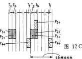
Figure 12 a illustrates the track part form to 6 times of Vn trick modes of forward.That follows as can be seen, respectively organizes one group of 12 track part that 12 track parts will repeat.Certainly, 12 track parts of those groups of following are comprising the information of different trick modes.Figure 12 b illustrates the form of Figure 12 a respectively with the form of each several part P1+~P4+ among track part Ta, Tb, Th, the Tf.Yet Figure 12 b is illustrated in the form that has repeated cubic graph 12a in 12 track parts of that group.The result is track part part P '
1+~P ' 4+ comes across respectively among track part Te, Tf, Tl, the Tj, and herein, part Pq+ is identical with the information content of P ' q+, and herein, q gets 1~4.And, the part P among track part Ti and the Tj is shown "
1+~P "
4+Part P "
3+And P "
4+Appear in 12 track parts of next group, so not shown.Part P "
1+Equate part P with the information content of P1 "
2+Equate with the information content of P2.Now, as can be seen, in Figure 12 b, respectively organize four track parts, that is: one group of one group of track part Te~Th or Ti~Tl.These groups have same form, also have same information.
In another embodiment of extraordinary image Figure 12 b form, can see three full groups together, four track parts with same content, that is: Ta~Td, Te~Th, Ti~Tl track part group.Two groups of track part Te~Th, Ti~Tl have been identical.Now, part P "
3+From the position of its track part 12 track parts of next group, move among the track part Td on the same position; Part P "
4+Also from the position of its track part 12 track parts of next group, move among the track part Tb on the same position, it is identical with other two groups of 4 track parts to make this group track part Ta~Td become.Obviously, part P in utilizing track part Ti "
1+, navigate to the part P in the track part Td "
3+, and/or navigate to part P in the track part Tb "
4+During the regeneration, now, part P "
3+And/or P "
4+In information come too early, therefore, before handling, should rotate the message delay head drum of reading from these two parts time in one week.
Figure 12 c illustrates the form of Figure 12 a respectively with the form of each several part P1+~P4+ among track part Ta, Tb, Th, the Tf.Yet Figure 12 c is illustrated in the form that has repeated twice Figure 12 a in 12 track parts of that group.The result is track part part P '
1+, P '
2+, P '
4+Come across respectively among track part Tg, Th, the Tl.Part P '
3+Appear in 12 track parts of next group, so not shown.Part P '
1+Equate part P ' with the information content of P1
2+, equate with the information content of P2.Now, as can be seen, in Figure 12 c, respectively organize 6 track parts.That is: one group of track part Tg~Tl.6 track parts of respectively organizing then have same form, but do not comprise same information.But, still can be part P '
3+From the position of its track part 12 track parts of next group, move in first group of 6 track part Ta~Tf on the position identical in the track part Tb with the position of part P3+ in the track part Th.Obtain 6 track parts of two identical groups with this method,, in trick mode, utilized part P ' herein
1+With part P "
3+The time, from part P '
3+Information come too early.
Be noted that because one group of 12 track part of search last longer than search one group of 4 track part or one group of 6 track part, so, because have that the form of Figure 12 b or 12c makes in trick mode, between reading duration in, lock comparatively fast.The also discussion of face as follows.
Figure 13 illustrates, to the track part form of 9 times of Vn trick modes of forward.Have people's demonstration, can be in the track part part of track part T1, T2, T10, T19, T20 the information stores of trick mode.Yet, at this moment, strictly be locked on those track parts that comprise the trick mode message part in order to make magnetic head, need very long locking time.
Therefore, can see one group of 18 track part, herein, each the track part part that has from the lower-left to upper right hachure, information is identical; Have from each track part part of hachure left to bottom right, the information content also is identical.Like this, the information content of track part T1, T2, T4 repeats twice in 18 track parts of that group.That is: in track part T7 and T13, in the each several part, repeat that part of interior information content among the track part T1; In track part T8, T10, T14 and T16 in the each several part, repeat among track part T2 and the T4 information content of (their information content is same) in the each several part.
During with 9 times of Vn trick mode regeneration, now, the speed that can come the controlling recording carrier with such method, promptly, make magnetic head be locked in each group one of three pairs of track parts part, make magnetic head can read the trick mode information of record in each group last (below, will illustrate).Because three positions that make the magnetic head locking in each group, occur, so required locking time is shorter.
Suppose that scanner configurations is according to Fig. 1 a or 1c, then a pair of magnetic head Ai, Bi can scan in respectively organizing in 18 track parts of following: track part is to T1, T2, T19, T20, or the like; Perhaps, track part is to T7, T8, T25, T26, or the like; Perhaps, track part is to T13, T14, T31, T32, or the like in each several part.Suppose that scanner configurations is according to Fig. 1 b, then magnetic head A, B respectively organize in 18 track parts and can scan what follow: track part is to T1, T10, T19, T28, or the like; Perhaps, track part is to T7, T16, T25, T34, or the like; Perhaps, track part is to T13, T22, T31, T40 (not shown), or the like in each several part.
As can see from Figure 13, can the trick mode information of right-9 times of Vn trick modes be inserted in each middle track part to be equivalent to method described above.
Figure 14 illustrates, to the track part form of 27 times of Vn trick modes of forward.Perhaps the someone proves, can be the information stores of trick mode in the track part part of track part T1, T2, T28, T55, T56.Yet, at this moment, strictly be locked on those track parts that comprise the trick mode message part in order to make magnetic head, need longer locking time.
Therefore, can see one group of 54 track part, herein, each the track part part that has from the lower-left to upper right hachure, information is identical; Have from each track part part of hachure left to bottom right, the information content also is identical.Like this, the information content of track part T1, T2, T4 repeats 8 times in 54 track parts of that group.That is: in track part T7, T13, T19, T25, T31, T37, T43 and T49, in the each several part, repeat that part of interior information content among the track part T1; In track part T8, T10, T14, T16, T20, T22, T26, T28, T32, T34, T38, T40, T44, T46, T50 and T52, in the each several part, repeat the information content of each several part interior (their information content is same) among track part T2 and the T4.
During with 27 times of Vn trick mode regeneration, now, the speed that can come the controlling recording carrier with such method, promptly, make magnetic head be locked in each group one of nine pairs of track parts part, make magnetic head can read the trick mode information of record in each group last (below, will illustrate).Because nine positions that make the magnetic head locking in each group, occur, so required locking time is shorter.
Suppose that scanner configurations is according to Fig. 1 a or 1c, then a pair of magnetic head Ai, Bi can scan in respectively organizing in 54 track parts of following: track part is to T1, T2, T55, T56, or the like; Perhaps, track part is to T7, T8, T61, T62 (this two, not shown), or the like; Perhaps, track part is to T13, T14, T67, T68 (this two, not shown), or the like; Perhaps, track part is to T19, T20, T73, T74 (this two, not shown), or the like in each several part.Suppose that scanner configurations is according to Fig. 1 b, then magnetic head A, B respectively organize in 54 track parts and can scan what follow: track part is to T1, T28, T55, T82 (not shown), or the like; Perhaps, track part is to T7, T34, T61, T88 (this two, not shown), or the like; Perhaps, track part is to T13, T40, the each several part among T67, T94 (this two, not shown) or the like.
As can see from Figure 14, can the trick mode information of right-27 times of Vn trick modes be inserted in each middle track part to be equivalent to method described above.
Figure 15 illustrates the combination track part form that is used for allowing 3 times, 9 times, 27 times trick modes of forward.Trick mode information to the 3Vn trick mode is respectively organized in 6 track parts to be included in reference to figure 5 illustrated methods.Among Figure 15, each group of 6 track parts is designated as G3.1~G3.6.Trick mode information to the 9.Vn trick mode is included in the illustrated method of reference Figure 13 respectively organizes in 18 track parts.Among Figure 15, each group of 18 track parts is designated as G18.1~G18.2.Trick mode information to the 27.Vn trick mode is included in the illustrated method of reference Figure 14 respectively organizes in 54 track parts.Among Figure 15, only show 54 groups that track part is such, and incomplete, be designated as G27.1.
As seen from Figure 15, when the speed of trick mode improved, the each several part length of each trick mode speed reduced.Its reason is, when the speed of trick mode improved, the transversal record carrier of track part and magnetic head time was passed through the angle increase between the path, and the part of feasible each the bar track part that can read is shorter.
When the speed of record carrier is n times of Vn, as the common conclusions of trick mode, can see a group of 2P bar track part, in this group, trick mode is stored in the each several part of each bar track part in this group.P is the factor of digital n.As an example, suppose that n is 30.30 the factor is 2,3,5,6,10,15,30.Like this, can see and respectively organize 4 track parts or respectively organize 6 track parts or respectively organize 10 track parts or respectively organize 12 track parts or respectively organize 20 track parts or respectively organize 30 track parts or respectively organize 60 track parts.In most of the cases, we can say that the information that comprises repeats in n/p group in a group.According to the example of Figure 14, n=27, therefore P=3,9 groups of 6 track parts that have the same information content in the track part part occurred.
And, should be noted that, in order to compensate the inexactness of servo system (this system should strictly be positioned the magnetic head path in each group on the each several part), may require the trick mode information repeated several times that handle must be stored in each track part part in a track part, make that under the coarse situation in location magnetic head also can be read the information of trick mode from the track part part.
Figure 16 illustrates has some record carriers that record the skewed track on it 40.Figure 16 also illustrates the path that is designated as label 120, is designated as one of reading head of 52 and scans this record carrier by this path with trick mode.When along the path during 120 scanning record carriers, the magnetic head 52 with one of two azimuths can only be from read message on the track part of even-numbered or odd-numbered.
For regeneration video information in allowing during trick-play modes, be under the situation about noting particularly with data compression form in video information, requirement increases specific special play-back information on the certain location in track part, make in trick-play modes to the various possible tape running speeds of record carrier magnetic head 52 those positions of scanning.This special play-back information is except recording the normal play video information in the track part and the particular video information of record.The result is to make certain part (for example, the part 122 in the track part 124) of track part comprise this special play-back information that magnetic head 52 should scan and read under trick-play modes.More precisely, formed along record carrier 40 vertically operation, have with above-mentioned group form be included in trick mode information in the track part, be designated as a strap of 126.
Here, should be noted that, the video information that in track part, the video data of normal manner of playback record is comprised data compression, at video data is under the situation of MPEG video data, should be noted that, for the video information that realizes such data compression, the information corresponding to an images is carried out intraframe coding, so that obtain so-called I frame.By two images are carried out interframe encode, first image is formed the I frame, second image is formed the P frame, can obtain higher data compression.In order to reproduce that two images, must carry out intraframe decoder (the anti-processing of intraframe coding) to the I frame information, so that recover first image; And, must utilize I frame information and P frame information to carry out interframe decoding (the anti-processing of interframe encode), so that recover second image.Like this, the normal play video data that write down in track part comprise the sequence information that relates to I frame and P frame.And the B frame also appears in this sequence, still, can not use the method identical with the P frame, independently the B frame decoding, but need be from other visual information.Further describing of relevant mpeg information signal standard, the file in the reference paper inventory (4).
Figure 17 illustrates a sequence of coding image, so that obtain the MPEG vision signal.Image with " I " indication is the image of intraframe coding.The P image and the B image of the I image of intraframe coding and the I that follows in intraframe coding image back are called group of picture (GOP), and this is a regulation item known in the vision signal mpeg encoded.During " normal play " handled, whole images shown in Figure 17 are handled, so that conduct " normal play " data record is to record carrier.
As an example, in trick mode, only the I frame information is used as trick mode information as required, record in the each several part of track part with the form of further packed data.
An embodiment of tape deck is shown to Figure 18 principle.This tape deck comprises the input 11 that is used for receiving the MPEG serial data stream that is used for being recorded in the track part.Input 11 is coupled on the input 12 of " normal play " processing unit 14.And, " special play-back " processing unit 16 also is provided, " special play-back " processing unit 16 has the input 17 that also is coupled on the input 11.The output 19 and 20 of " normal play " processing unit 14 and " special play-back " processing unit 16 is coupled on the respective input of multicircuit switch 22.
The auxiliary signal generator 24 that is used to provide the auxiliary signal information that is used for storing in the track part is provided.The output of multicircuit switch 22 and generator 24 is coupled on the respective input of error correction coding unit 26.The error correction coding step can be carried out in the error correction coding unit 26 that is designated as ECC2.The next error correction coding step that is designated as ECC1 is carried out in error correction coding unit 28.
Tape deck also comprises and is used for adding id information so that add the generator 30 of subcode information.After in assembled unit 32, signal combination being got up, the signal that has made up is added on the unit 34, in unit 34, carry out coding, incoming bit stream in the word of each 24 bits be for conversion into the word of 25 bits, in unit 34, add synchronizing information.
The output of coding unit 34 is coupled on the input of r/w cell 36, in r/w cell 36, by means of at least two write heads the traffic logging that obtains with coding units 34 to the record carrier in the skewed track.R/w cell 36 has one of scanner configurations shown in Figure 1.
In order to allow to detect and correct mistake in the regenerating unit that will discuss after a while, the error correction coding step that is designated as ECC1 and ECC2 is needs.
" normal play " processing unit 14 will be further described, because such description is irrelevant with explanation the present invention.Yet, be noted that in early time No. (PHN14818) the U.S. Patent application book that proposes with same full name of applicant, promptly, the file in the lists of documents (6), provided tape deck and described widely, so that " normal play " in relating to during the record of mpeg information signal handled.Therefore, this part application is classified reference here as.
Before " special play-back " processing unit 16 is further described in to Figure 18 tape deck, at first, this regenerating unit is described from principle.
An embodiment who is used for from the regenerating unit of regenerating information on the record carrier 40 of Figure 19 tape deck acquisition is shown to Figure 19 principle.This regenerating unit comprises reads unit 50, reads unit 50 and has according to one of Fig. 1 scanner configurations, is used for from record carrier 40 at least two reading heads of read message the skewed track.The output of reading unit 50 is coupled on the input of decoding unit 54,54 pairs of signals of being read of this decoding unit are carried out 25 to 24 decodings, so that the word of 25 bits in the input traffic is for conversion into the word of 24 bits.After in selected cell 56, unwanted those information concerning the copy that reproduces original mpeg data stream having been eliminated, then, in error correction unit 58, carry out error correction.Obviously, performed error correction has two steps.An error correction step is based on ECC1, and an error correction step is based on ECC2.
The output of error correction unit 58 is coupled on the input of " normal play " processing unit 60.And, " special play-back " processing unit 62 also is provided, " special play-back " processing unit 62 has the input that also is coupled on error correction unit 58 outputs.The output 64 and 65 of " normal play " processing unit 60 and " special play-back " processing unit 62 is coupled on the respective input a and b of switch 66, the c of switch 66 end is coupled on the output 68.If regenerating unit is switched to " normal play " regeneration, this means record carrier with the normal speed tape transport, allow 60 work of " normal play " processing unit, switch 66 switches on the position of a-c.If regenerating unit is switched to " special play-back " regeneration (being also referred to as " feature mode "), this means record carrier with the normal speed tape transport, allow 62 work of " special play-back " processing unit, switch 66 switches on the b-c position.
In order to allow " special play-back " regeneration, regenerating unit also has tape-servo control device 70, and tape-servo control device 70 produces and is used for the control signal of controlling recording carrier 40 speed.More precisely, control device 70 produces control signal in " special play-back " regeneration period, make record carrier 40 such tape transports, that is: Figure 12 a and have Fig. 1 a or the example of 1c scanner configurations in, make that a pair of magnetic head A, B strictly stride across each to track part Ta, Tb, Tm, Tn ... or the like in the hatching part; Perhaps, at Figure 12 a and have in the example according to Fig. 1 b scanner configurations, make that a pair of magnetic head A, B strictly stride across each to track part Ta, Tf/Th ... or the like in the hatching part.In the example of Figure 12 b, control device 70 produces control signal, makes and scans: belong to 4 those groups of track part Ta~Td; Perhaps, that is a kind of for 4 track part Te~Th; Perhaps, the each several part in 4 those group track parts of track part Ti~Tl.In the example of Figure 12 c, control device 70 produces control signal, makes and scans: belong to 6 those groups of track part Ta~Tf; Perhaps, the each several part in 6 those group track parts of track part Tg~Tl.Further specify the function of Servocontrol device 70 below with reference to Figure 21.
Should also be noted that the file (6) that the front is mentioned in the lists of documents done widely to describe to regenerating unit, so that " normal play " that relate in the mpeg information signal regeneration period handled.
In the file (6) of lists of documents, how (for example illustrated by means of tape deck, the DVC type), " normal play " storage that " normal play " processing unit 14 is provided is to record carrier in the track part of (for example, the record carrier of DVC type).
More precisely, Figure 20 is illustrated in the form of track part 1 on the record carrier.The left end of track part 1 is the starting point of track part among Figure 20, and the right-hand member of this track part is the finish line part of track part.Track part comprises some track part parts.The track part that is designated as G1 partly is front signal track part part.In the document (1), the example of front signal track part part G1 has been described widely.
Be right after track part part G1 back be to follow the tracks of single-tone recording section TP1, this part is designated as ITI (insertion timing information) track part part, this part comprises single-tone, synchronizing information, identification (or the regularly) information of following the tracks of.Further specifying of ITI track part content can be found in document (3).
Be right after is edit gap G2 in track part part TP1 back.Be right after edit gap G2 back be track part part TP2, according to the DVC form, this track part part TP2 is the audio signal recording district, comprises digitized audio message.In file (6), show that this track part partly comprises parity information.Be right after edit gap G3 back be track part part TP3, according to the DVC form, this track part part TP3 is a video signal recording 8, comprises digital video information.In file (6), show, in this track part part, storing the information that " normal play " processing unit 14 and " special play-back " processing unit 16 produce.Be right after edit gap G4 back be track part part TP4, this track part partly is designated as INDEX (index), comprises subcode information in this track part part, for example, absolute and/or relative time information, catalogue listing (TOC).Track part part G5 makes the track part termination.We can say that the order that each several part TP1, TP2, TP3 occur can be different in each bar track part.
Figure 21 provides the content in TP3 district.In fact, illustrate to Figure 21 principle and be designated as j=1~149, have 149 horizontal line of the information byte that is stored in wherein.In fact, this 149 behavior sequentially is stored in 149 blocks (perhaps, synchronization blocks) among the recording areas TP3.In each block, storing the information of 90 bytes that are designated as i=1~i=90.
It is the synchronization structure of 2 bytes that preceding 2 bytes (i=1 and i=2) of each block form length.In each block, back to back 3 bytes form the ID sign indicating number, wherein, comprise the information of pointing out this block sequence number in recording section TP3.Last 8 bytes in the block form horizontal parity check information.The vertical check information stores is in the end in the memory cell that comprises i=6 to i=82 of 11 blocks.
According to the present invention, the byte of " normal play " information that " normal play " processing unit 14 is produced and in encoder 34, encode, and the block that " special play-back " information process unit 16 produces and the bytes store of " special play-back " information of coding has sequence number j=3~j=137 in encoder 34 comprises in the memory cell of i=6~i=82.The bytes store of auxiliary data have sequence number j=1,2,138 block comprises in the memory cell of i=6~i=82.Block sequentially is stored among the track part part TP3, from being designated as the block of y=1, and then is the block that is designated as j=2, or the like, until be designated as the block of j=149.
Being stored in the auxiliary data that is designated as in j=1,2,138 the block can be teletext data or control data.
Here, be noted that and auxiliary data be stored in the different units of memory regulation.In this respect, Figure 13 in the reference paper (1), is stored in auxiliary data in the memory portion that is designated as III herein.
More precisely, synchronization blocks comprises " normal play " information or " special play-back " information.File (6) has been described the storage of " normal play " information in signal (or the synchronously) piece widely.
Now, the present invention is intended to " special play-back " information in the stored information blocks.
In the block that is designated as j=3~137, only can be used for " special play-back " information that storage " special play-back " information unit 16 produces for 77 bytes that are designated as j=6~82.Can understand from file (6), preceding two bytes are specialized in and are inserted all types of additional datas usefulness of (for example, the numbering of block and/or identification signal piece comprise still " special play-back " information of " normal play " information) in each block.So in each block, surplus have 75 bytes to use.Like this, can " special play-back " information stores on be arranged at reference in some pieces in those pieces in the track part part of figure 2~15 identification.
Be noted that in the regeneration period of trick mode, reading head stride across track part scanning during in, be not that all data blocks shown in Figure 21 of described track part can both be read.Under these circumstances, can only read direct those blocks in succession.The result is, can not carry out the error correction that utilizes vertical check information in during trick mode.In each block, can only be used for carrying out error correction to 8 horizontal parity bytes, yet such error correction is compared with the error correction of vertical check byte with having carried out level, it is much weak that error correction is wanted.
For further protection " special play-back " information, prevent the mistake that in record and the regeneration step followed, may occur, the error correction coding step additional to " special play-back " information and executing is so that obtain coding " special play-back " information signal of zero defect.Below, will this additional error correction coding step be described with reference to Figure 22,23,24.
At first, the Servocontrol device of Figure 19 will be further specified.As mentioned above, between the reading duration of trick mode in, can only read some blocks of in track part part TP3, storing, therefore, the error correction in block can only be carried out based on the horizontal parity bytes in described.Whether correct this form about trick mode information included in the block indication.If correct, Servocontrol device 70 is seen Figure 21 with regard to included id information in the i=3,4 of detecting signal piece, 5 bytes.In id information, comprise track part information and block information.Like this, servomechanism installation 70 can be discerned the block of just having read and be in which bar track part, and in a track part in which unit.Which track part Servocontrol device also has the trick mode information stores in, and the information in which block in track part.The result is, when track part number and block number and required track part number and block are number inconsistent, controls tape running speed like this, makes correct track part and correct block are read out.
An embodiment of " special play-back " processing unit 16 in Figure 18 tape deck is shown to Figure 22 principle, should " special play-back " processing unit 16 have the input 17 on the input 82 that is coupled to " special play-back " information extraction unit 80, and be coupled to the output 84 on the input 85 of error correction coding unit 81.Unit 80 is adaptive to and extracts " special play-back " information the information signal (for example being mpeg information signal) on being provided to input 17.As having illustrated in early time, this means, from mpeg information stream, extract the I frame.Error correction coding unit 81 is to " special play-back " information and executing error correction coding." special play-back " information signal of error correction coding is provided on the output 20, and sort signal will be stored in some blocks of 75 bytes.
Below, will performed two kinds of possible error correction codings in error correction coding unit 81 be discussed.In first error correction coding,,, see Figure 23 so that obtain 8 additional parity bytes (in the case) to being stored in " special play-back " information and executing error correction coding of 67 bytes in the block.Figure 23 illustrates the content of a block, i.e. the content of a horizontal line among Figure 21.Now, available 77 bytes in each block, storage: that discuss, that comprise additional identification information in early time two bytes then are 67 bytes and 8 additional parity bytes of " special play-back " information.
With reference to Figure 24, the method for another kind of error correction coding is described.Figure 24 illustrates a sequence of 25 blocks (in this example), is storing " special play-back " information of 75 bytes in each block of this sequence.On the vertical direction of Figure 24, carry out the error correction coding step, form the additional parity information (in this example) of 5 blocks.Now, the sequence of these 30 blocks is stored in each track part part discussed above.Be noted that and just can store the sequence of these 30 blocks in the different track part parts into as long as can regenerate full detail in during " special play-back " mode.
An embodiment of " special play-back " processing unit 62 in Figure 19 regenerating unit is shown to Figure 25 principle.The input that is somebody's turn to do " special play-back " processing unit 62 is coupled on the input that detects unit 90 and selected cell 91.Detect unit 90 and be adaptive to included identifying information in two bytes that detect in Figure 23 the block that is designated as " additional information ", this identifying information is discerned those blocks and is comprised " normal play " data or comprise " special play-back " data.In the file (6), this identification signal has been discussed widely.Comprise " special play-back " information in response to having detected in the block, detector 90 produces detecting signal on its output 97, this detecting signal is provided on the signal input end 98 of selected cell 91.In response to receiving this detecting signal, select to comprise the block of " special play-back " information the data flow of selected cell 91 on being added to its input 99, and, the block of selecting like this is provided on the output that is coupled on error correction unit 93 inputs, and error correction unit 93 is under the influence of additional parity information shown in Figure 23 or Figure 24, detect and correct step to the data execution error that is added on its input." special play-back " data of error correction are provided on " special play-back " decoding unit 95, and " special play-back " decoding unit 95 recovers to be used for the pictorial information that shows with trick-play modes from the information that received.
List of references (1) No.492 704 (PHN13.546) european patent application book (2) No.93,202,950 (PHN14.241) european patent application book (3) No.93,201,263 (PHN14.449) european patent application book on February 22nd, (4) 1994, " HDTV of Major Leagues system specialization " (draft) (5) No.5142421 (PHN13.537) US Patent specification (6) sequence number is U.S. Patent application book (7) No.5109271 (PHN12.975) US Patent specification (8) No.509 594 (PHN13.668) european patent application book (9) No.93.00.746 (PHN14.515) the european patent application book of No. (PHN14.818)
Claims (18)
1. the tape deck of recording digital video signals in the skewed track that is used on magnetic recording medium, this tape deck comprises:
-be used for the input of receiving digital video signal,
-be used for to this digital video signal carry out chnnel coding, to obtain to be suitable for recording the channel coding device of the channel signal in the track part on the described record carrier;
-be used for channel signal is write write device in the track part, this write device comprise be arranged on around the rotary head cylinder, at least the first and second different write heads of azimuth of head gap;
It is characterized in that this tape deck also has:
Be used for drawing the trick mode information generator of trick mode video signal from digital video signal; Be adaptive to trick mode video signal and digital video signal are encoded, so that obtain the channel coding device of compound channel signal at its output; From being suitable for that this compound channel signal is written to write device in the track part, this track part is used for realizing the regeneration of trick mode in having the regenerating unit of read apparatus, this device is used for reading the compound channel signal from track part, read apparatus has at least the first and second reading heads, these two magnetic head assemblies are set on the head drum, make their position around head drum, be separated from each other a certain angle, perhaps, make it to form two and couple together a pair of magnetic head that is provided with side by side securely, the azimuth of first and second head gaps of read apparatus equals the azimuth of first and second write heads in the write device substantially, in described trick mode the tape running speed of record carrier be specified tape running speed in the regeneration period of normal play n doubly, herein, n is an integer, and comprise factor P greater than 1, channel coding device is adaptive to such method trick mode video signal is encoded: make in one group of 2P bar track part, the trick mode video signal of having encoded is recorded in described one group of 2P bar track part first, second, in the part of the 3rd track part, article first and second, track part is adjacent track part, the trick mode information of encoding that is stored in that part of article one track part is different with the trick mode of coding information in being stored in that part of second track part, and the trick mode information of encoding in that part of the 3rd track part of being stored in equals to be stored in the message part of the interior trick mode of encoding at least of that part of one of article one and second track part.
2. according to the tape deck described in the claim 1, it is characterized in that, when P is odd number, in one group of 2P bar track part, adjacent article one and second track part and the 3rd track part be spaced apart P-2 bar track part.
3. according to the tape deck described in the claim 1, it is characterized in that, utilize azimuth and the identical magnetic head of magnetic head that is used at that a part of inner storag information one of described in article one and the second track part, be recorded in the information of that a part of stored in the 3rd track part.
4. according to the tape deck described in the claim 1,2 or 3, it is characterized in that, for with equal in the normal play regeneration period specified tape running speed-n doubly, the tape running speed of record carrier in described second trick mode, realize the regeneration of second trick mode in described regenerating unit, the trick mode information generator also is adaptive to from digital video signal and draws second trick mode video signal; Channel coding device is adaptive to such method becomes second trick mode video signal of encoding to second trick mode video signal coding: in described one group of 2P bar track part, described second trick mode video signal of having encoded is recorded in described one group of 2P bar track part the 4th, the 5th, article six, in the part of track part, article four and the 5th, track part is adjacent track part, the trick mode information of encoding that is stored in that part of the 4th track part is different with the trick mode of coding information in being stored in that part of the 5th track part, and the trick mode information of encoding in that part of the 6th track part of being stored in equals to be stored in the message part of that a part of interior trick mode of encoding at least of one of the 4th and the 5th track part.
5. according to the tape deck described in the claim 4, it is characterized in that, when P is odd number, in one group of 2P bar track part, adjacent the 4th and the 5th track part and the 6th track part be spaced apart P-2 bar track part.
6. according to the tape deck described in the claim 4, it is characterized in that in one group of 2P bar track part, article one is different with the 5th track part with the 4th with the second track part.
7. according to the tape deck described in the claim 6, it is characterized in that,, be set in each bar track part on the essentially identical position that part in article one, second, the 4th and the 5th track part.
8. according to the tape deck described in the claim 4, it is characterized in that, utilize azimuth and the identical magnetic head of magnetic head that is used at that a part of inner storag information one of described in the 4th and the 5th track part, be recorded in the information of that a part of stored in the 6th track part.
9. according to the tape deck described in the claim 1,2 or 7, it is characterized in that n is an odd number; That part in article one, second and the 3rd track part, be set in each bar track part on the essentially identical position.
10. according to the tape deck described in the claim 4,5 or 7, it is characterized in that n is an odd number; That part in the 4th, the 5th and the 6th track part, be set in each bar track part on the essentially identical position.
11. the tape deck according to described in the claim 1,2 or 7 is characterized in that n is an even number; That part in article one and the second track part is set in each bar track part on the essentially identical position; That part at least the three track part, be set on the different position of that part in position and article one and the second track part in track part.
12. the tape deck according to described in the claim 4,5 or 6 is characterized in that n is an even number; That part in the 4th and the 5th track part, be set in each bar track part on the essentially identical position; That part at least the six track part is set on position different with that part in the 4th and the 5th track part, position in track part.
13., it is characterized in that if n/p is not equal to 1 integer, then one group of 2P bar track part repeats n/p time according to the tape deck described in each before in the claim.
14., it is characterized in that the trick mode information generating apparatus also has the encoder for correcting that is used for to trick mode information and executing error correction coding step according to the tape deck described in each before in the claim.
15. one kind with the record carrier that obtains according to the tape deck described in each before in the claim.
16. one kind is used for it is characterized in that from the regenerating unit according to regenerating digital video frequency signal the skewed track on the magnetic recording medium described in the claim 15 this regenerating unit comprises:
-be used for reading the read apparatus of compound channel signal from track part, this read apparatus comprise be arranged on around the rotary head cylinder, at least the first and second different reading heads of azimuth of head gap, composite video signal comprises channel signal and the trick mode video signal of having encoded
-be used for from the choice device of the compound channel signal recovery channel signal and the trick mode video signal of having encoded,
-be used for a channel signal channel-decoding, so that obtain the channel decoding device of digital video signal;
-be used for the trick mode video signal decoding of encoding, so that obtain the trick mode video signal decoding device of second digital video signal;
-be used to provide the output of the digital video signal or second digital video signal;
Also be; for to equal doubly record carrier tape running speed of the specified tape running speed n of record carrier, to realize the regeneration of trick mode; read apparatus is adaptive to by means of first magnetic head and reads the trick mode information of encoding in that part from article one track part of one group of 2P bar track part; and; by means of reading the trick mode information of encoding in second magnetic head that part from second track part or the 3rd track part; herein, P is the factor greater than 1.
17. the regenerating unit according to described in the claim 16 is characterized in that, the trick mode video signal decoding device also has and is used for trick mode information, the execution error of reading from track part detected and correct the error correction device of step.
18. according to the regenerating unit described in claim 16 or 17, it is characterized in that, comprise and be used for the controlling recording bearer rate, make in each group track part that a part of Servocontrol device in that part or the 3rd track part in that part, the second head scanning second track part in first head scanning article one track part.
Applications Claiming Priority (2)
| Application Number | Priority Date | Filing Date | Title |
|---|---|---|---|
| EP94200943.2 | 1994-04-12 | ||
| EP94200943 | 1994-04-12 |
Publications (1)
| Publication Number | Publication Date |
|---|---|
| CN1149951A true CN1149951A (en) | 1997-05-14 |
Family
ID=8216776
Family Applications (1)
| Application Number | Title | Priority Date | Filing Date |
|---|---|---|---|
| CN95193393A Pending CN1149951A (en) | 1994-04-12 | 1995-03-29 | Recording and reproduction of trick mode video signal |
Country Status (9)
| Country | Link |
|---|---|
| US (1) | US5751889A (en) |
| EP (2) | EP0820200B1 (en) |
| JP (2) | JPH09511634A (en) |
| KR (1) | KR100379346B1 (en) |
| CN (1) | CN1149951A (en) |
| AT (2) | ATE186439T1 (en) |
| DE (2) | DE69515343T2 (en) |
| HK (1) | HK1013184A1 (en) |
| WO (1) | WO1995028061A2 (en) |
Families Citing this family (11)
| Publication number | Priority date | Publication date | Assignee | Title |
|---|---|---|---|---|
| JP3289045B2 (en) * | 1994-04-12 | 2002-06-04 | 三菱電機株式会社 | Digital recording and playback device |
| GB2326791B (en) * | 1994-04-12 | 1999-02-10 | Mitsubishi Electric Corp | Digital VTR |
| JP3226444B2 (en) * | 1995-01-25 | 2001-11-05 | 三菱電機株式会社 | Digital signal recording device and reproducing device |
| US5778139A (en) * | 1995-05-29 | 1998-07-07 | Samsung Electronics Co., Ltd. | Digital video data recording with outer-error-correction coding of trick-play data and apparatus for use therewith |
| ATE218241T1 (en) * | 1996-01-19 | 2002-06-15 | Koninkl Philips Electronics Nv | RECORDING OF A DATA-REDUCED DIGITAL VIDEO SIGNAL IN SLOW TRACKS ON A RECORDING MEDIUM |
| JP3774929B2 (en) * | 1996-03-21 | 2006-05-17 | ソニー株式会社 | Data reproducing apparatus and data reproducing method |
| US6078448A (en) * | 1997-01-21 | 2000-06-20 | U.S. Philips Corporation | Recording of subcode signals in slant tracks on a record carrier |
| US6222981B1 (en) | 1997-02-03 | 2001-04-24 | U.S. Philips Corporation | Recording of trick play signals on a record carrier |
| KR20000064857A (en) * | 1997-02-03 | 2000-11-06 | 엠. 제이. 엠. 반 캄 | Apparatus and method for recording a plurality of trick-play signals on a record carrier |
| ATE278239T1 (en) * | 1997-02-03 | 2004-10-15 | Koninkl Philips Electronics Nv | SYNCHRONOUS BLOCK NUMBERING OF TRICK PLAYBACK SIGNALS DURING THE RECORDING OF SUCH SIGNALS ONTO A RECORDING MEDIUM |
| TW417089B (en) * | 1998-02-11 | 2001-01-01 | Koninkl Philips Electronics Nv | Reproduction of a digital information signal in a trick play reproduction mode |
Family Cites Families (12)
| Publication number | Priority date | Publication date | Assignee | Title |
|---|---|---|---|---|
| JP2684695B2 (en) * | 1988-08-05 | 1997-12-03 | キヤノン株式会社 | Data recording device |
| US5335116A (en) * | 1989-05-09 | 1994-08-02 | Mitsubishi Denki Kabushiki Kaisha | Method and apparatus for recording analog video signal in compressed digital format |
| NL8901661A (en) * | 1989-06-30 | 1991-01-16 | Philips Nv | TV SYSTEM FOR DIGITAL TRANSFER OF IMAGE SIGNALS. |
| NL9002772A (en) * | 1990-09-21 | 1992-04-16 | Philips Nv | DEVICE FOR RECORDING A DIGITAL INFORMATION SIGNAL IN A RECORD CARRIER. |
| NL9002839A (en) * | 1990-12-21 | 1992-07-16 | Philips Nv | DEVICE FOR RECORDING "CLOCK RUN-IN" CODE WORDS AT THE BEGINNING OF A TRACK ON A MAGNETIC RECORD CARRIER. |
| KR0134177B1 (en) | 1992-03-24 | 1998-04-22 | Toshiba Kk | Variable length code recording playback apparatus |
| KR100195071B1 (en) * | 1992-07-14 | 1999-06-15 | 윤종용 | Method and device for recording/reproducing digital video signals |
| JP3546434B2 (en) * | 1992-12-25 | 2004-07-28 | ソニー株式会社 | Video signal playback device |
| DE69423794T2 (en) | 1993-01-13 | 2000-12-28 | Hitachi Ltd | Device for recording digital video signals with playback at variable speed |
| US5377051A (en) * | 1993-01-13 | 1994-12-27 | Hitachi America, Ltd. | Digital video recorder compatible receiver with trick play image enhancement |
| KR940018849A (en) * | 1993-01-28 | 1994-08-19 | 프레데릭 얀 스미트 | Arrangement for recording a video signal and a corresponding audio signal in slant tracks on a longitudinal magnetic record carrier, and record carrier obtained by means of the arrangement) |
| DE69425788T2 (en) * | 1993-05-27 | 2001-01-04 | Matsushita Electric Ind Co Ltd | Digital video recorder for high-resolution video signals with high-resolution display in special playback modes |
-
1995
- 1995-03-29 KR KR1019960705796A patent/KR100379346B1/en not_active IP Right Cessation
- 1995-03-29 CN CN95193393A patent/CN1149951A/en active Pending
- 1995-03-29 WO PCT/IB1995/000213 patent/WO1995028061A2/en active IP Right Grant
- 1995-03-29 DE DE69515343T patent/DE69515343T2/en not_active Expired - Fee Related
- 1995-03-29 AT AT95911482T patent/ATE186439T1/en not_active IP Right Cessation
- 1995-03-29 EP EP97203310A patent/EP0820200B1/en not_active Expired - Lifetime
- 1995-03-29 AT AT97203310T patent/ATE190183T1/en active
- 1995-03-29 JP JP7526208A patent/JPH09511634A/en not_active Ceased
- 1995-03-29 EP EP95911482A patent/EP0755611B1/en not_active Expired - Lifetime
- 1995-03-29 DE DE69513161T patent/DE69513161T2/en not_active Expired - Fee Related
-
1997
- 1997-04-14 US US08/839,427 patent/US5751889A/en not_active Expired - Fee Related
-
1998
- 1998-12-21 HK HK98114125A patent/HK1013184A1/en not_active IP Right Cessation
-
2002
- 2002-03-29 JP JP2002096775A patent/JP2002369150A/en active Pending
Also Published As
| Publication number | Publication date |
|---|---|
| EP0820200A2 (en) | 1998-01-21 |
| DE69515343T2 (en) | 2000-09-21 |
| KR100379346B1 (en) | 2003-06-19 |
| ATE190183T1 (en) | 2000-03-15 |
| US5751889A (en) | 1998-05-12 |
| ATE186439T1 (en) | 1999-11-15 |
| JPH09511634A (en) | 1997-11-18 |
| EP0755611B1 (en) | 1999-11-03 |
| DE69513161T2 (en) | 2000-05-25 |
| DE69515343D1 (en) | 2000-04-06 |
| EP0820200B1 (en) | 2000-03-01 |
| JP2002369150A (en) | 2002-12-20 |
| WO1995028061A3 (en) | 1995-11-23 |
| HK1013184A1 (en) | 1999-08-13 |
| EP0755611A1 (en) | 1997-01-29 |
| DE69513161D1 (en) | 1999-12-09 |
| EP0820200A3 (en) | 1998-02-25 |
| WO1995028061A2 (en) | 1995-10-19 |
Similar Documents
| Publication | Publication Date | Title |
|---|---|---|
| CN1168300C (en) | Apparatus and method for TV broadcast copy protection | |
| CN1146902C (en) | Digital recording/reproducing method and apparatus for video having superposed subinformation | |
| CN1291595C (en) | Optical disk and play optical disk method | |
| CN1104724C (en) | Information recording medium, recording method and reproduction apparatus | |
| US7519266B1 (en) | Eliminating picture format artifacts in MPEG trick modes | |
| US6097877A (en) | Digital recording and reproducing apparatus which multiplexes and records HDTV, SDTV and trick play data together on a magnetic tape | |
| CN1220762A (en) | Recording of trick play signal on record carrier | |
| US6118922A (en) | Recording and reproduction of a trick mode video signal | |
| CN1149951A (en) | Recording and reproduction of trick mode video signal | |
| CN1138402A (en) | Storage and retrieval of a data reduced digital video signal in/from a memory and recording and preproduction of a data reduced digital video signal on a longitudinal record carrier | |
| CN1184809C (en) | Data processing device and method, and recording device and method | |
| CN1132316C (en) | Data processing device and data recording device | |
| US6959141B1 (en) | Data reproduction apparatus and reproduction method | |
| CN1507746A (en) | Information processing apparatus and method | |
| MXPA04004140A (en) | Changing a playback speed for video presentation recorded in a modified film format. | |
| CN1114211C (en) | Method and device for recording and reproducing video signal | |
| KR100927180B1 (en) | Moving picture coding apparatus and moving picture coding method | |
| CN1255802C (en) | Sync block numbering of trick play signal during recording of such signals on record carrier | |
| JP2002514861A (en) | Trick play reproduction of MPEG encoded signal | |
| EP0815558B1 (en) | Recording of a data reduced digital video signal in slant tracks on a record carrier | |
| EP1005226A2 (en) | MPEG reproducing apparatus and methods | |
| CN1220801A (en) | Recording of trick play signals on record carrier | |
| CN1113358C (en) | Recording of trick play signal in helical scan type recording apparatus | |
| JP4120056B2 (en) | Playback apparatus and playback method | |
| CN101682716A (en) | Video signal processing device |
Legal Events
| Date | Code | Title | Description |
|---|---|---|---|
| C06 | Publication | ||
| PB01 | Publication | ||
| C10 | Entry into substantive examination | ||
| SE01 | Entry into force of request for substantive examination | ||
| AD01 | Patent right deemed abandoned | ||
| C20 | Patent right or utility model deemed to be abandoned or is abandoned |