CN114991308A - Assembled light steel composite board building structure - Google Patents
Assembled light steel composite board building structure Download PDFInfo
- Publication number
- CN114991308A CN114991308A CN202210602448.5A CN202210602448A CN114991308A CN 114991308 A CN114991308 A CN 114991308A CN 202210602448 A CN202210602448 A CN 202210602448A CN 114991308 A CN114991308 A CN 114991308A
- Authority
- CN
- China
- Prior art keywords
- light steel
- stair
- wallboard
- plate
- staircase
- Prior art date
- Legal status (The legal status is an assumption and is not a legal conclusion. Google has not performed a legal analysis and makes no representation as to the accuracy of the status listed.)
- Pending
Links
- 229910000831 Steel Inorganic materials 0.000 title claims abstract description 181
- 239000010959 steel Substances 0.000 title claims abstract description 181
- 239000002131 composite material Substances 0.000 title claims abstract description 20
- 239000011241 protective layer Substances 0.000 claims abstract description 56
- 239000011083 cement mortar Substances 0.000 claims abstract description 41
- 239000004567 concrete Substances 0.000 claims abstract description 39
- 239000011381 foam concrete Substances 0.000 claims abstract description 19
- 239000004575 stone Substances 0.000 claims abstract description 3
- 239000010410 layer Substances 0.000 claims description 48
- 238000009434 installation Methods 0.000 claims description 29
- 230000002457 bidirectional effect Effects 0.000 claims description 6
- 229910001294 Reinforcing steel Inorganic materials 0.000 claims description 4
- 238000010276 construction Methods 0.000 abstract description 41
- 238000009413 insulation Methods 0.000 abstract description 8
- 238000000034 method Methods 0.000 abstract description 7
- 230000008569 process Effects 0.000 abstract description 6
- 238000004321 preservation Methods 0.000 abstract description 4
- 230000002265 prevention Effects 0.000 abstract description 4
- 230000008901 benefit Effects 0.000 description 10
- 239000000463 material Substances 0.000 description 9
- 239000002585 base Substances 0.000 description 8
- 210000001503 joint Anatomy 0.000 description 7
- 239000004570 mortar (masonry) Substances 0.000 description 7
- 230000009286 beneficial effect Effects 0.000 description 6
- 238000003466 welding Methods 0.000 description 6
- 230000000149 penetrating effect Effects 0.000 description 5
- 230000000694 effects Effects 0.000 description 4
- 239000007788 liquid Substances 0.000 description 4
- XLYOFNOQVPJJNP-UHFFFAOYSA-N water Substances O XLYOFNOQVPJJNP-UHFFFAOYSA-N 0.000 description 4
- 230000009471 action Effects 0.000 description 3
- 239000003513 alkali Substances 0.000 description 3
- 238000009435 building construction Methods 0.000 description 3
- 239000004744 fabric Substances 0.000 description 3
- 241000761557 Lamina Species 0.000 description 2
- 238000005336 cracking Methods 0.000 description 2
- 238000006073 displacement reaction Methods 0.000 description 2
- 230000001174 ascending effect Effects 0.000 description 1
- 230000004888 barrier function Effects 0.000 description 1
- 238000005452 bending Methods 0.000 description 1
- 238000005253 cladding Methods 0.000 description 1
- 230000009194 climbing Effects 0.000 description 1
- 230000008878 coupling Effects 0.000 description 1
- 238000010168 coupling process Methods 0.000 description 1
- 238000005859 coupling reaction Methods 0.000 description 1
- 238000005034 decoration Methods 0.000 description 1
- 230000002349 favourable effect Effects 0.000 description 1
- 239000003365 glass fiber Substances 0.000 description 1
- 238000004519 manufacturing process Methods 0.000 description 1
- 238000012986 modification Methods 0.000 description 1
- 230000004048 modification Effects 0.000 description 1
- 230000035515 penetration Effects 0.000 description 1
- 230000000750 progressive effect Effects 0.000 description 1
- 230000001681 protective effect Effects 0.000 description 1
- 239000002356 single layer Substances 0.000 description 1
- 239000003643 water by type Substances 0.000 description 1
Images


Classifications
-
- E—FIXED CONSTRUCTIONS
- E04—BUILDING
- E04B—GENERAL BUILDING CONSTRUCTIONS; WALLS, e.g. PARTITIONS; ROOFS; FLOORS; CEILINGS; INSULATION OR OTHER PROTECTION OF BUILDINGS
- E04B1/00—Constructions in general; Structures which are not restricted either to walls, e.g. partitions, or floors or ceilings or roofs
- E04B1/343—Structures characterised by movable, separable, or collapsible parts, e.g. for transport
-
- E—FIXED CONSTRUCTIONS
- E04—BUILDING
- E04B—GENERAL BUILDING CONSTRUCTIONS; WALLS, e.g. PARTITIONS; ROOFS; FLOORS; CEILINGS; INSULATION OR OTHER PROTECTION OF BUILDINGS
- E04B1/00—Constructions in general; Structures which are not restricted either to walls, e.g. partitions, or floors or ceilings or roofs
- E04B1/38—Connections for building structures in general
- E04B1/61—Connections for building structures in general of slab-shaped building elements with each other
- E04B2001/6195—Connections for building structures in general of slab-shaped building elements with each other the slabs being connected at an angle, e.g. forming a corner
-
- Y—GENERAL TAGGING OF NEW TECHNOLOGICAL DEVELOPMENTS; GENERAL TAGGING OF CROSS-SECTIONAL TECHNOLOGIES SPANNING OVER SEVERAL SECTIONS OF THE IPC; TECHNICAL SUBJECTS COVERED BY FORMER USPC CROSS-REFERENCE ART COLLECTIONS [XRACs] AND DIGESTS
- Y02—TECHNOLOGIES OR APPLICATIONS FOR MITIGATION OR ADAPTATION AGAINST CLIMATE CHANGE
- Y02A—TECHNOLOGIES FOR ADAPTATION TO CLIMATE CHANGE
- Y02A30/00—Adapting or protecting infrastructure or their operation
- Y02A30/24—Structural elements or technologies for improving thermal insulation
- Y02A30/244—Structural elements or technologies for improving thermal insulation using natural or recycled building materials, e.g. straw, wool, clay or used tires
Abstract
The invention discloses an assembled light steel composite board building structure, which belongs to the technical field of buildings and comprises a wallboard, a floor panel and a wallboard corner connecting piece for connecting the wallboard; the wall plate and the floor plate both comprise light steel keels which are welded in a crossed manner, and foam concrete is filled in a space formed by the light steel keels in a crossed manner; cement mortar protective layers are paved on two side faces of the light steel keel of the wallboard; and fine stone concrete protective layers and cement mortar protective layers are respectively paved on the upper side surface and the lower side surface of the light steel keel of the floor panel. The light steel keel can be recycled, so that a large amount of steel is prevented from being consumed in the house building process; the cross-welded light steel keel is combined with the light foam concrete, so that good bearing capacity and light weight can be guaranteed, the heat preservation, fire prevention and sound insulation performance is good, the light steel keel can be formed in a factory in a modularized mode, the housing industrialization can be realized, the field construction workload is reduced, the assembly construction speed is high, the assembly rate is high, the field wet operation is less, and the construction period is greatly shortened.
Description
Technical Field
The invention belongs to the technical field of buildings, and particularly relates to an assembled light steel composite board building structure.
Background
With the greatly increased demand of people for houses, the requirements on living conditions are higher and higher, so that the construction industry is rapidly developed.
The prefabricated building is characterized in that structural components are prefabricated in advance in a processing plant and connected through methods such as mechanical connection and the like on a construction site, and the single components are assembled into a whole. The comparison of the assembly type building and the cast-in-place building can find that the assembly type building components are only required to be manufactured in advance in a prefabricating factory, and the construction site only needs mechanical connection, so that the construction time is greatly reduced, the overall construction cost is reduced, and meanwhile, the requirement of green development is met.
But present prefabricated assembly type building, its fire behavior, thermal insulation performance, sound insulation performance and structural stability can not better guarantee, and the various connected node structure of wallboard, floor board is complicated, and whole construction is loaded down with trivial details, leads to the limitation of use great.
Disclosure of Invention
In order to solve the problems, the invention provides an assembled light steel composite board building structure which has good heat preservation, fire prevention, sound insulation and bearing performance, and is green and environment-friendly; and the workload of site construction can be reduced, and the construction period is shortened.
The invention is realized by the following technical scheme:
an assembled light steel composite board building structure comprises a vertically-installed wallboard, a horizontally-installed floor board and a wallboard corner connecting piece which is arranged at a corner and used for connecting the wallboard;
the wall plate and the floor plate both comprise light steel keels which are welded in a crossed manner, and foam concrete is filled in a space formed by the light steel keels in a crossed manner;
cement mortar protective layers are paved on two side faces of the light steel keel of the wallboard; and a fine aggregate concrete protective layer and a cement mortar protective layer are respectively paved on the upper side surface and the lower side surface of the light steel keel of the floor panel.
The invention further improves that a bidirectional steel wire mesh is arranged in the cement mortar protective layer.
The invention is further improved in that a bidirectional reinforcing steel bar net rack is arranged in the fine aggregate concrete protective layer.
The invention further improves that the light steel keel is of a channel steel structure, and wing plates on two sides of the light steel keel are arranged in a manner of being tightly attached to plate surfaces on two sides.
The invention is further improved in that two edges of the light steel keel are bent inwards to form flanges.
The invention is further improved by that the wallboard corner connecting piece comprises a vertical column vertically arranged at a corner position and a corner wallboard connected to the side surface of the vertical column and used for connecting the wallboard; the corner wall plate comprises light steel keels which are welded in a crossed mode, foam concrete is filled in a space formed by the light steel keels in a crossed mode, cement mortar protective layers are paved on the outer sides of the corner wall plate and the outer sides of the stand columns, and the light steel keels in the corner wall plate in the transverse direction are welded with the side faces of the stand columns; the upright post is of a square steel tube structure, and a fine aggregate concrete filling layer is filled in the upright post.
The invention is further improved by also comprising a stair connected between the upper and lower floors; the stair comprises an upper stair body and a lower stair body, and a stair middle plate is connected between the upper stair body and the lower stair body; the stair intermediate plate comprises light steel keels which are welded in a crossed mode, foam concrete is filled in a space formed by the light steel keels in a crossed mode, and fine aggregate concrete protective layers and cement mortar protective layers are laid on the upper side face and the lower side face of each light steel keel of the stair intermediate plate respectively.
The invention is further improved in that when the stairs are bottom stairs, the lower end of the lower stair body is connected and installed with the foundation through the fixing bolt; a stair supporting beam which is used for supporting the upper end of the lower stair body and the middle stair plate together, supporting the lower end of the upper stair body and the middle stair plate together and supporting the upper end of the upper stair body and the upper floor panel together is arranged between the left side wall plate and the right side wall plate of the staircase; the upper end of the lower stair body, the upper end and the lower end of the upper stair body, the stair middle plate and the floor plate on the upper layer are respectively connected and installed with the stair supporting cross beam through fixing bolts.
The invention further improves the structure that when the staircase is a non-bottom staircase, a staircase supporting beam which is used for supporting the lower end of the lower staircase body and the lower floor slab together, the upper end of the lower staircase body and the middle staircase slab together, the lower end of the upper staircase body and the middle staircase slab together and the upper end of the upper staircase body and the upper floor slab together is arranged between the left side wall board and the right side wall board of the staircase; the upper and lower ends of the lower stair body, the upper and lower ends of the upper stair body, the stair middle plate, the upper and lower floor slab are respectively connected with the stair supporting beam through fixing bolts for positioning and installation.
The invention is further improved by that an intermediate plate supporting frame for supporting and mounting the rear part of the intermediate plate of the staircase is mounted on the rear side wall plate of the staircase; and the wall plates on the left side and the right side of the staircase are respectively provided with a beam support frame for supporting a staircase support beam.
According to the technical scheme, the invention has the beneficial effects that:
the light steel keel in the wallboard and the floor slab can be recycled, so that a large amount of steel is prevented from being consumed in the building construction process, and the environment is protected; and the light steel keel is welded in a crossed manner and combined with the light foam concrete, so that good bearing capacity and light weight can be ensured, the building block has good heat preservation, fire prevention and sound insulation properties, can be formed in a factory in a modularized manner, is beneficial to realizing housing industrialization, greatly reduces the field construction workload, and has the advantages of high assembly construction speed, high assembly rate, less field wet operation and greatly shortened construction period.
Drawings
In order to more clearly illustrate the technical solution of the present invention, the drawings used in the description will be briefly introduced, and it is obvious that the drawings in the following description are only some embodiments of the present invention, and it is obvious for those skilled in the art that other drawings can be obtained based on these drawings without creative efforts.
FIG. 1 is a schematic top sectional view of a building structure according to an embodiment of the present invention.
FIG. 2 is a schematic side sectional view of a building structure according to an embodiment of the present invention.
Fig. 3 is a schematic view of a wall panel structure according to an embodiment of the present invention.
Fig. 4 is a schematic side sectional view of a wall panel in accordance with an embodiment of the present invention.
FIG. 5 is a schematic top cross-sectional view of one embodiment of a wall panel in accordance with embodiments of the present invention.
Fig. 6 is a schematic top cross-sectional view of another embodiment of a wall panel of the present invention.
Fig. 7 is a schematic sectional view of a floor panel according to an embodiment of the present invention.
Fig. 8 is a schematic top view of a floor panel according to an embodiment of the present invention.
Fig. 9 is a schematic structural view of a first connecting member and a second connecting member according to an embodiment of the present invention.
Fig. 10 is a schematic view of an embodiment of a wall panel butt-joint structure according to the embodiment of the present invention.
Fig. 11 is a schematic view of another embodiment of a wall panel butt joint structure according to an embodiment of the present invention.
Figure 12 is a top cross-sectional view of an L-shaped wall panel corner connector according to an embodiment of the present invention.
Fig. 13 is a schematic cross-sectional view of a-a in fig. 12.
Figure 14 is a top cross-sectional view of a T-shaped wall panel corner connector according to an embodiment of the present invention.
FIG. 15 is a schematic cross-sectional view of B-B in FIG. 14.
Fig. 16 is a schematic cross-sectional view of C-C in fig. 14.
Figure 17 is a top cross-sectional view of a cross wall panel corner connector according to an embodiment of the present invention.
Fig. 18 is a schematic cross-sectional view of D-D in fig. 17.
Figure 19 is a schematic view of a wall panel and foundation connection according to an embodiment of the present invention.
Fig. 20 is a schematic view of the connection of the outer wall panel and the middle floor panel according to the embodiment of the present invention.
Fig. 21 is a schematic cross-sectional view of E-E in fig. 20.
Fig. 22 is a schematic sectional view of F-F in fig. 20.
Fig. 23 is a schematic sectional view of G-G in fig. 20.
FIG. 24 is a schematic view of the connection of the exterior wall panel to the top floor panel according to the embodiment of the present invention.
Fig. 25 is a schematic sectional view of H-H in fig. 24.
Fig. 26 is a schematic view of the connection of the inside wall panel and the middle floor panel according to the embodiment of the present invention.
FIG. 27 is a schematic sectional view taken along line I-I in FIG. 26.
Fig. 28 is a schematic cross-sectional view of J-J in fig. 26.
FIG. 29 is a schematic cross-sectional view of K-K in FIG. 26.
FIG. 30 is a schematic view of a second connector installation in accordance with an embodiment of the present invention.
FIG. 31 is a schematic cross-sectional view of P-P in FIG. 30.
Fig. 32 is a schematic view of the connection of the inside wall panel and the top floor panel according to the embodiment of the present invention.
FIG. 33 is a cross-sectional view of L-L in FIG. 32.
FIG. 34 is a schematic cross-sectional view of M-M in FIG. 32.
FIG. 35 is a schematic cross-sectional view of N-N of FIG. 32.
Fig. 36 is a schematic top view of a staircase according to an embodiment of the present invention.
FIG. 37 is a schematic cross-sectional view of R-R in FIG. 36.
FIG. 38 is a cross-sectional view of T-T in FIG. 36.
Fig. 39 is a schematic structural view of a staircase body according to an embodiment of the present invention.
Fig. 40 is a schematic view of a connection structure of a lower step body and a foundation base according to an embodiment of the present invention.
Fig. 41 is a schematic view of the connection structure of the stair climbing body and the floor slab according to the embodiment of the present invention.
Fig. 42 is a schematic view of a connection structure of a lower stair body and a middle plate of a stair according to an embodiment of the present invention.
Fig. 43 is a schematic view of a connection structure of the stair ascending body and the stair middle plate according to the embodiment of the present invention.
Fig. 44 is a schematic view of an intermediate plate support bracket mounting structure according to an embodiment of the present invention.
Fig. 45 is a schematic view of a cross beam support bracket mounting structure according to an embodiment of the present invention.
In the drawings: 100. wallboard, 200, floor panel, 300, foundation base, 400, stair, 500, corner wallboard, 1, light steel keel, 2, foam concrete, 3, cement mortar protective layer, 4, steel wire mesh, 5, wallboard connection post-pouring protective layer, 6, rivet, 7, connecting steel plate, 8, upright post, 9, fine aggregate concrete filling layer, 10, fine aggregate concrete protective layer, 11, reinforcing steel bar net rack, 12, first connecting piece, 13, wallboard installation post-pouring protective layer, 14, sitting pulp layer, 15, second connecting piece, 16, connecting bolt, 17, fire-proof plate, 18, downstairs body, 19, upstairs body, 20, stair intermediate plate, 21, stair supporting beam, 22, intermediate plate supporting frame, 23, beam supporting frame, 24, fixing bolt, 25, groove.
Detailed Description
In order to make the objects, features and advantages of the present invention more obvious and understandable, the technical solutions of the present invention will be clearly and completely described below with reference to the accompanying drawings in the present embodiment, and it is apparent that the embodiments described below are only a part of embodiments of the present invention, and not all embodiments. All other embodiments, which can be derived by a person skilled in the art from the embodiments given herein without making any creative effort, shall fall within the scope of protection of this patent.
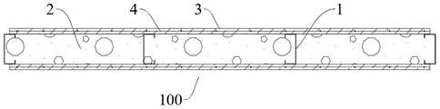
As shown in fig. 1-2, is an assembled light steel composite panel building structure; the whole structure is a two-storey structure and comprises a wallboard 100 which is vertically installed, a floor panel 200 which is horizontally installed and a wallboard corner connecting piece which is arranged at a corner and is connected with the wallboard 100;
as shown in fig. 3-8, the wall panel 100 and the floor panel 200 both comprise cross-welded light gauge steel 1, the cross-welded light gauge steel 1 thereby forming a support frame, and the rectangular space formed by the cross-welding of the light gauge steel 1 is filled with lightweight foam concrete 2;
cement mortar protective layers 3 are paved on two side surfaces of the supporting frame of the wallboard 100; the upper and lower sides of the supporting frame of the floor panel 200 are respectively paved with a fine stone concrete protective layer 10 and a cement mortar protective layer 3. The two sides of the wallboard 100 and the lower side surface of the floor panel 200 are protected by cement mortar protective layers 3, so that good structural performance is ensured; the side is protected through fine aggregate concrete protective layer 10 on floor board 200, as the face of often trampling, guarantees good barrier propterty and sound insulation.
The supporting frames in the wall plate 100 and the floor plate 200 can be recycled, so that a large amount of steel is prevented from being consumed in the building construction process, and the environment is protected; and the light steel keel 1 is welded in a crossed manner and combined with the light foam concrete 2, so that good bearing capacity and light weight can be guaranteed, the heat-insulation fireproof performance is good, the light steel keel can be formed in a modularized manner in a factory, the housing industrialization can be realized, the field construction workload is greatly reduced, the assembly construction speed is high, the assembly rate is high, the field wet operation is less, and the construction period is greatly shortened.
As shown in fig. 5-7, a bidirectional steel wire mesh 4 is arranged in the cement mortar protective layer 3, and the diameter of meshes of the steel wire mesh 4 is 2.5 mm. The cement mortar protective layer 3 is structurally reinforced through the steel wire mesh 4 so as to improve the integrity of the cement mortar protective layer 3; in addition, in order to prevent cracking, alkali-resistant glass fiber mesh cloth needs to be pasted on the outer side of the cement mortar protective layer 3 during plastering.
As shown in fig. 7-8, a bidirectional steel bar net rack 11 is arranged in the fine aggregate concrete protective layer 10, and the aperture of the steel bar net rack 11 is 6 mm. The whole bearing capacity of the floor plate 200 is improved through the reinforcing steel bar net rack 11, and the structural strength of the floor plate 200 is ensured.
Wherein, the light steel keel 1 is in a channel steel structure, and wing plates at two sides of the light steel keel are arranged to be clung to plate surfaces at two sides. The light steel keel 1 of the channel steel structure has light weight and good structural performance, ensures that the wallboard 100 and the floor panel 200 have the characteristics of light weight and good bearing performance, and is convenient to prefabricate and assemble.
Wherein, two edges of the light steel keel 1 are bent inwards to form flanges. The bending resistance of the light steel keel 1 is improved, and the good structural performance of the support frame is ensured; and the connection firmness with the foam concrete 2 is improved.
Wherein, the setting is broken to the vertical light gauge steel 1 of wallboard 100 logical long setting, horizontal light gauge steel 1, and the vertical light gauge steel 1 of wallboard 100 is a whole piece of logical long promptly, and horizontal light gauge steel 1 welds between adjacent vertical light gauge steel 1. Guarantee the convenience of light gauge steel 1 welding construction, vertical light gauge steel 1 leads to long the setting, can be convenient for the butt joint of two wallboard 100.
As shown in fig. 10-11, is a wall panel butt joint structure; the longitudinal light steel keels 1 on the left and right end faces of the wallboard 100 are not completely poured, namely, the longitudinal light steel keels protrude out of the left and right end faces of the wallboard 100 and are half exposed; the light steel keels 1 longitudinally protruding from the adjacent wall boards 100 are connected and installed through connecting components; wall board connecting post-pouring protective layers 5 are laid on two sides of the protruding parts (exposed parts) of the light steel keels 1 on the left and right end surfaces of the wall board 100. Connect adjacent wallboard 100 convex light gauge steel 1 through coupling assembling to water protective layer 5 through the wallboard connection after and cover the protection, guarantee wallboard 100 and wallboard 100 butt joint's convenience and firm nature.
The wallboard connecting post-cast protective layer 5 is made of cement mortar, alkali-resistant gridding cloth is laid on the outer side of the wallboard connecting post-cast protective layer 5, the alkali-resistant gridding cloth extends out of 100mm towards two sides respectively, and a gap between the wallboard connecting post-cast protective layer 5 and the cement mortar protective layer 3 of the wallboard 100 is connected and covered, so that good protective performance and anti-cracking performance are guaranteed.
In one embodiment, as shown in fig. 10, the openings of the light gauge steel 1 protruding from the left and right end surfaces of the wall board 100 are inward, and the connecting component is a connecting steel plate 7 welded between the webs of the light gauge steel 1 of two adjacent wall boards 100. The webs of the light steel keels 1 which are tightly attached to the left side and the right side are welded through the connecting steel plates 7, the thickness of each connecting steel plate 7 is 6mm, and fillet welds h are formed f 6 mm; connect stably firm, the construction is convenient, avoids the thermal deformation and the penetration phenomenon that two adjacent light gauge steel 1 webs direct weld produced, supports the welding through connecting plate 7, guarantees welded structural performance. The connection is dry connection, the installation is rapid, each part can be prefabricated in a factory, and the assembly rate is high; the construction efficiency is high, the period is short, the influence of weather materials is small, compared with the traditional concrete structure, the construction process is simple, the construction time is short, and the advantage is particularly obvious under extreme weather conditions; and the energy is saved, the environment is protected, namely, the energy, the land, the water and the materials are saved, and the environment is protected, so that the green construction concept is embodied.
In another embodiment, as shown in fig. 11, the opening direction of the light gauge steel 1 convexly disposed on the left and right end surfaces of the wall board 100 is outward, the wing plates of the light gauge steel 1 of the adjacent wall board 100 are staggered and attached, that is, they are "hand-picking" type butt-jointed, and the connecting component is a rivet 6 penetrating through the wing plates of the two light gauge steel 1. The upper wing plate and the lower wing plate of the two adjacent light steel keels 1 are riveted through the rivets 6, the structure is simple, the construction is convenient and fast, welding is not needed, and the practicability is good.
As shown in fig. 11, a fine aggregate concrete filling layer 9 is poured into a space formed by abutting two adjacent light steel keels 1, and the connecting part of the wallboard 100 and the wallboard 100 is structurally reinforced, so that the construction difficulty caused by welding of the traditional thick steel plate can be effectively overcome, the construction requirement of an assembly type steel structure building can be more easily met, and the advantages of the assembly type building are brought into play; the concrete column is equivalent to a steel tube concrete column, effectively improves the constraint effect on core concrete, is more beneficial to fully exerting the performance advantages of two materials, and improves the bearing capacity of the column; the integrity, the stability and the anti-seismic performance are good, and the implementation and the popularization of the composite material in practical engineering are facilitated.
As shown in fig. 12-18, are wall panel corner connectors; comprises a vertical column 8 vertically arranged at the corner position of a building and a corner wallboard 500 connected with the side surface of the vertical column 8; the structure of the corner wallboard 500 is basically the same as that of the wallboard 100, the corner wallboard 500 comprises a light steel keel 1 of a channel steel structure which is welded transversely and vertically in a crossed manner, a space formed by the light steel keel 1 in a crossed manner is filled with foam concrete 2, a cement mortar protective layer 3 is paved on the outer sides of the corner wallboard 500 and the upright post 8, and the transverse light steel keel 1 in the corner wallboard 500 is welded with the side face of the upright post 8. Through the welding of stand 8 and horizontal light gauge steel 1, lay cement mortar protective layer 3 in its outside, wallboard corner connecting piece integrated into one piece structure can simplify the wallboard connected node of corner position in the building structure to corner wallboard 500 through wallboard corner connecting piece docks the installation with other wallboard 100, can realize the modularization equipment, has reduced the construction degree of difficulty, has improved the efficiency of construction. And the bearing capacity and the structural performance of the corner position of the building structure can be improved by the integrated wallboard corner connecting piece.
Wherein, the upright column 8 is of a square steel pipe structure, and a fine aggregate concrete filling layer 9 is filled in the upright column. The column 8 is filled with the fine aggregate concrete filling layer 9, which is equivalent to the action of a steel pipe concrete column, effectively improves the constraint effect on core concrete, is more favorable for fully exerting the performance advantages of two materials, and improves the bearing capacity of the column.
Wherein, according to concrete building structure corner shape, can form L type wallboard corner connecting piece, T type wallboard corner connecting piece and cross wallboard corner connecting piece.
The vertical column 8 may be a multi-face tubular structure, and the corner wall panels 500 are connected to different sides of the vertical column 8 to adapt to various corner forms of the building structure.
The light steel keel 1 of the corner wallboard 500 far away from one end face of the upright post 8 is longitudinally arranged in a through length mode, and is not poured completely, namely, the light steel keel protrudes out of the end face of the corner wallboard 500, is exposed by half and has the same structure as the left end face and the right end face of the wallboard 100. And the projected light steel keel 1 is opened inwards or outwards, and forms two butt joint modes of the wallboard corner connector and the wallboard 100, which are the same as the two butt joint modes of the wallboard, and the butt joint modes are not explained here. Thereby realizing convenient, firm and stable connection and installation of the wallboard corner connecting piece and the wallboard 100.
Wherein, the horizontal light gauge steel 1 of wallboard 100 bottom is set up in its bottom surface of protrusion, and its opening is upwards, namely the horizontal light gauge steel 1 wing plate of wallboard 100 bottom exposes outside, here does not lay the protective layer 3 of cement mortar; the opening of the transverse light steel keel 1 at the top of the wallboard 100 is downward, and the cement mortar protective layer 3 is not paved on the upper end surface of the wallboard 100, namely, the upper side of the web plate of the transverse light steel keel 1 at the top of the wallboard 100 is exposed outside.
As shown in fig. 19, which is a connection structure of the wall panel 100 and the foundation base 300; the light steel keel 1 transversely arranged at the bottom of the wallboard 100 is convexly arranged on the lower end surface of the wallboard 100, and the opening of the light steel keel is upwards arranged; a plurality of first connecting pieces 12 of a U-shaped structure for covering, positioning and connecting the light steel keels 1 transversely arranged at the bottom of the wallboard 100 are arranged on the foundation 300 at intervals, and wallboard installation post-pouring protective layers 13 made of cement mortar are laid on the outer sides of wing plates on two sides of each first connecting piece 12. The first connecting piece 12 of a plurality of U type structure on the foundation base 300 carries out block location installation to wallboard 100 to pour protective layer 13 and pave with the cement mortar protective layer 3 of wallboard 100 after the wallboard installation of cement mortar, carry out the cladding to connected node. The wallboard 100 and the foundation 300 are integrally in dry connection, the installation is fast, all the parts can be prefabricated in a factory, and the assembly rate is high; the construction efficiency is high, the period is short, the influence of weather materials is small, compared with the traditional concrete structure, the construction process is simple, the construction time is short, and the advantage is particularly obvious under extreme climatic conditions; and the energy is saved, the environment is protected, namely, the energy, the land, the water and the materials are saved, and the environment is protected, so that the green construction concept is embodied.
As shown in fig. 19, the web of the first connecting member 12 and the foundation base 300 are positioned and installed by expansion bolts, a setting layer 14 of cement mortar is laid between the web of the light steel keel 1 at the bottom of the bottom wall board 100 in the transverse direction and the web of the first connecting member 12, and the setting layer 14 of cement mortar is also laid between the web of the light steel keel 1 at the bottom of the wall board 100 and the foundation base 300; the wing plates are arranged in an inner-outer fit mode and are positioned and installed through screws. The head of the expansion bolt protruding out of the upper side of the web plate of the first connecting piece 12 is covered by the sitting pulp layer 14, and the sitting pulp layer 14 at the position of the first connecting piece 12 is flush with the sitting pulp layers 14 at other positions, so that the light steel keel 1 at the bottom of the wallboard 100 is completely attached to the sitting pulp layers 14, and the stability of supporting and installing the wallboard 100 is ensured; the connection structure of the first connecting piece 12 and the light steel keel 1 at the bottom of the wallboard 100 is simple, convenient to construct and easy to disassemble and assemble.
Wherein, the floor panel 200 is all around with wallboard 100 overlap joint supporting part be two light gauge steel 1 that are close to the setting, and when prefabricating, foam concrete 2 is not pour to light gauge steel 1 position here to be connected with wallboard 100 when convenient construction and install.
As shown in fig. 20-25, the connection structure of the outer wall panel 100 and the floor panel 200 is shown; two light steel keels 1 on the outer terminal surface of floor panel 200 are close to the setting, and the pterygoid lamina support of its lower part is installed on the light steel keel 1 web at the top of next floor outer panel 100 to respectively pass through screw location installation. Two openings of the light steel keels 1 on the outer end face of the floor panel 200 are arranged oppositely, and a space formed by the two openings is filled with a fine aggregate concrete filling layer 9. The outer side wall plate 100 of next layer supports the installation to two light gauge steel 1 pterygoid laminas of floor panel 200 terminal surface to fill fine aggregate concrete filling layer 9, can realize that wallboard 100 supports floor panel 200's stability, firm, guarantee the convenience of construction. The beam is equivalent to a steel pipe concrete beam, effectively improves the constraint effect on core concrete, is more beneficial to fully playing the performance advantages of two materials, and improves the bearing capacity of the beam.
When the floor panel 200 is installed on top, as shown in fig. 24-25, i.e. when the floor panel 200 is the top surface of a building, the wall panel installation post-cast protective layer 13 with cement mortar laid on the upper and outer sides of the two light steel keels 1 on the outer end surface of the floor panel 200 is flush with the outer side wall panel 100 and the surface of the floor panel 200. The two light steel keels 1 on the outer end face of the floor panel 200 are coated and protected through the wallboard mounting post-pouring protective layer 13, and convenience of construction is guaranteed. The connecting structure can be used for the top lapping of single-layer or multi-layer buildings.
When the floor panel 200 is installed in the middle, as shown in fig. 20-23, that is, when the floor panel 200 is a non-top surface of a multi-story building, the first connecting members 12 of U-shaped structures are spaced on the upper sides of two light steel keel 1 wing plates on the outer end surface of the floor panel 200, the web plate of the light steel keel 1 protruding from the bottom of the upper outer side wall panel 100 is supported and clamped in the first connecting members 12, and the wall panel installation post-pouring protective layer 13 made of cement mortar is laid on the outer sides of the wing plates on both sides of the first connecting members 12 and the outer end surface of the floor panel 200, so that the wall panel installation post-pouring protective layer 13 is flush with the surface of the outer side wall panel 100. Reliable and convenient installation of the non-top floor board 200 and the outer wall board 100 of the multi-storey building can be realized.
As shown in fig. 20, a web of the first connecting member 12 and upper wing plates of two light steel keels 1 on the outer end surface of the floor panel 200 are positioned and installed by screws, a mortar layer 14 of cement mortar is laid between the web of the light steel keel 1 at the bottom of the upper outer wall panel 100 and the web of the first connecting member 12, and the mortar layer 14 of cement mortar is also laid between the web of the light steel keel 1 at the bottom of the upper outer wall panel 100 and the upper wing plates of two light steel keels 1 on the outer end surface of the floor panel 200, and the two are flush; the wing plates of the two are placed in an inner-outer fit mode and are positioned and installed through screws. The connection structure of the upper outer wallboard 100 and the floor slab 200 is similar to the connection structure of the wallboard 100 and the foundation base 300, so that the wallboards 100 of the upper layer and the lower layer have the same prefabricated production specification and good universality. The sitting thick liquid layer 14 through cement mortar covers the screw head portion of protrusion in first connecting piece 12 web upside to make the sitting thick liquid layer 14 of first connecting piece 12 position flush with the sitting thick liquid layer 14 of other positions, guarantee that the light gauge steel 1 of upper story wallboard 100 bottom laminates with sitting thick liquid layer 14 completely, guarantee the stationarity that supports upper story wallboard 100.
As shown in fig. 26-35, the connection structure of the inner wall panel 100 and the floor panel 200 is shown; the light steel keel 1 at the supporting position of the floor panel 200 and the inner side wall panel 100 is exposed, namely the foam concrete 2 is not poured on the light steel keel 1 of the floor panel 200; the second connecting pieces 15 of two U-shaped structures are installed on the outer side of the exposed light steel keel 1 of the floor panel 200 in a wrapping mode, the light steel keel 1 at the top of the lower layer of the inner side wall plate 100 is connected to the lower sides of wing plates on the lower portions of the two second connecting pieces 15 in a supporting mode, and a fine aggregate concrete filling layer 9 is filled in the exposed position space of the light steel keel 1 of the floor panel 200. The web plate of the second connecting piece 15 is connected and installed with the web plate of the bare light steel keel 1 of the floor board 200 through a connecting bolt 16, and the web plates of the second connecting piece and the web plate are attached; the lower wing plate of the exposed light steel keel 1 of the floor board 200, the lower wing plate of the second connecting piece 15 and the top light steel keel 1 web plate of the next layer of inner side wall board 100 are sequentially connected and installed in a penetrating way through screws. The inner side wall plate 100 of the next layer is simple to support and connect the floor plate 200, convenient and fast to construct, and stable and firm in connection joint.
When the floor panel 200 is installed on the top, as shown in fig. 32, that is, when the floor panel 200 is the top surface of a building, the upper side of the upper wing plate of the second connecting member 15 and the upper side of the fine aggregate concrete filling layer 9 are both paved with the wallboard installation post-cast protective layer 13 of cement mortar, so that the wallboard installation post-cast protective layer 13 is flush with the upper side plate surface of the floor panel 200 and serves as the top surface of the building.
When the floor panel 200 is disposed in the middle, as shown in fig. 26, that is, when the floor panel 200 is a non-top surface of a building, the connection structure of the upper layer of inner wall panel 100 and the floor panel 200 is the same as the connection structure of the upper layer of outer wall panel 100 and the floor panel 200; the upside of 15 upper portion pterygoid laminas of second connecting piece is equipped with the first connecting piece 12 of U type structure, and the convex light gauge steel 1 in inboard wallboard 100 bottom of upper story supports the block in first connecting piece 12, waters protective layer 13 after the wallboard installation that is equipped with cement mortar in the outside of the pterygoid lamina of first connecting piece 12 both sides to water protective layer 13 and flush with the face of inboard wallboard 100 after making the wallboard installation.
The first connecting piece 12 web, the second connecting piece 15 upper portion wing plate and the exposed light steel keel 1 upper portion wing plate of the floor panel 200 are sequentially installed in a penetrating connection mode through screws, a mortar sitting layer 14 of cement mortar is laid between the light steel keel 1 web at the bottom of the upper layer of the inner side wall plate 100 and the first connecting piece 12 web, and the mortar sitting layer 14 of cement mortar is also laid between the light steel keel 1 web at the bottom of the upper layer of the inner side wall plate 100 and the exposed light steel keel 1 upper portion wing plate of the floor panel 200, and the two are aligned. The screw head protruding out of the upper side of the web plate of the first connecting piece 12 is covered by the mortar layer 14, so that the light steel keel 1 at the bottom of the upper layer of the inner side wallboard 100 is completely attached to the mortar layer 14, and the stability of supporting the upper layer of the inner side wallboard 100 is guaranteed.
Wherein, the light steel keel 1 wing plate at the bottom of the upper layer of inner side wall plate 100 and the wing plate of the first connecting piece 12 are positioned and installed through screws.
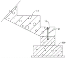
As shown in fig. 36-45, a stair configuration; when the building structure is a multi-storey building, a stair 400 is required to be installed between the upper and lower storeys; the stair 400 comprises an upper stair body 19 and a lower stair body 18, and a middle stair plate 20 connected and installed through the wall plates 100 is connected between the upper stair body 19 and the lower stair body 18; the structure of the stair middle plate 20 is the same as that of the floor plate 200, and comprises light steel keels 1 of a channel steel structure which are welded in a crossed mode, foam concrete 2 is filled in spaces formed by the light steel keels 1 in a crossed mode, fine aggregate concrete protective layers 10 and cement mortar protective layers 3 are laid on the upper side face and the lower side face of each light steel keel 1 of the stair middle plate 20 respectively, and foam concrete materials are adopted by an upper stair body 19 and a lower stair body 18, so that the stair middle plate has better structural performance and lighter quality. Whole stair 400 simple structure, the modularization equipment mode can effectively improve the convenience of construction, effectively shortens construction period.
When the stair 400 is arranged between the first floor and the second floor of the building, the lower end of the lower stair body 18 is connected with the foundation base 300 through the fixing bolt 24; a stair supporting beam 21 which is used for supporting the upper end of the lower stair body 18 and the middle stair plate 20 together, supporting the lower end of the upper stair body 19 and the middle stair plate 20 together and supporting the upper end of the upper stair body 19 and the upper floor panel 200 together is arranged between the left side wall plate 100 and the right side wall plate 100 of the staircase; the upper end of the lower stair body 18, the upper end and the lower end of the upper stair body 19, the stair middle plate 20 and the floor plate 200 on the upper layer are respectively connected and installed with the stair supporting beam 21 through fixing bolts 24. Through a dry type connecting mode of bolt connection, the contribution of the staircase to the overall rigidity of the structure is greatly reduced; meanwhile, the bolt connection mode can generate larger deformation displacement under the action of an earthquake, the acting force of the main body structure on the fabricated concrete stair can be reduced, and the fabricated concrete stair is protected. The stair structure can be applied to stair installation of a first floor and a second floor of a multi-floor building or stair installation of a second floor of the multi-floor building.
When the staircase 400 is arranged above three floors of a building structure, a staircase supporting beam 21 is arranged between the left side wall plate 100 and the right side wall plate 100 of the staircase for supporting the lower end of the lower staircase body 18 and the lower floor slab 200 together, supporting the upper end of the lower staircase body 18 and the middle staircase slab 20 together, supporting the lower end of the upper staircase body 19 and the middle staircase slab 20 together, and supporting the upper end of the upper staircase body 19 and the upper floor slab 200 together; the upper and lower ends of the lower stair body 18, the upper and lower ends of the upper stair body 19, the stair middle plate 20, the upper and lower floor boards 200 are respectively connected with the stair supporting beams 21 through fixing bolts 24 for positioning installation. The stair structure can be applied to the installation of more than three layers of stairs of a multi-layer building. Through a dry type connecting mode of bolt connection, the contribution of the staircase to the overall rigidity of the structure is greatly reduced; meanwhile, the bolt connection mode can generate larger deformation displacement under the action of an earthquake, the acting force of the main body structure on the fabricated concrete stair can be reduced, and the fabricated concrete stair is protected.
Wherein, the upper portion of the fixing bolt 24 junction position is seted up flutedly 25 to hold, keep away the nut of position and fixing bolt 24 swing joint installation, later stage uses mortar to cover, pave.
Wherein, the fixing bolt 24 is installed with the light steel keel 1 inside the floor panel 200 in a penetrating way, so that the reliability of the connection and installation of the fixing bolt 24 and the floor panel 200 is ensured.
Wherein, the stair supporting beam 21 is of an I-shaped steel structure. The stair supporting beam 21 has good structural strength and light weight, and convenience in construction and installation is guaranteed.
The left and right side wall plates 100 of the staircase are provided with middle plate support frames 22 for supporting and mounting the rear part of the staircase middle plate 20. The left wall plate 100 and the right wall plate 100 of the staircase are internally provided with two transverse light steel keels 1 with opposite openings and are also welded with the vertical light steel keels 1 in the staircase, the middle plate support frame 22 is of a square steel tube structure, and a web plate of the light steel keel 1 close to one side of the staircase is connected and installed with the middle plate support frame 22 through bolts. The middle plate support frame 22 is convenient to install and firm in fixation, and reliable support for the rear portion of the middle plate 20 of the stair is effectively achieved.
Wherein, the intermediate plate support frame 22 is filled with the fine aggregate concrete filling layer 9. The good bearing performance of the stair middle plate 20 is improved. The beam is equivalent to a steel pipe concrete beam, effectively improves the constraint effect on core concrete, is more beneficial to fully playing the performance advantages of two materials, and improves the bearing capacity of the beam.
The middle plate support frame 22 is installed in a penetrating connection with the light steel keel 1 in the middle plate 20 of the stair through the fixing bolt 24, and the reliability of the support connection of the middle plate support frame 22 to the middle plate 20 of the stair is guaranteed.
The middle plate support frame 22 is an L-shaped bent structure, and the rear surface of the middle plate support frame is connected and installed with the wall plate 100 at the rear side of the staircase in the same way as the connection with the left and right side wall plates 100 of the staircase. The middle plate support frame 22 is installed at the corner positions of the rear side wall plate 100 and the left and right side wall plates 100 of the staircase (actually, the L-shaped middle plate support frame 22 is installed at the corner position of the corner connecting member of the wall plate, which is not described herein since the corner wall plate 500 is similar to the wall plate 100 in structure), so as to effectively improve the reliable stability of the middle plate support frame 22 for supporting the middle plate 20 of the staircase.
Wherein, the left wall plate 100 and the right wall plate 100 of the staircase are respectively provided with a beam support frame 23 for supporting two ends of the staircase support beam 21. The connecting structure of the beam support frame 23 and the wall plate 100 is the same as that of the middle plate support frame 22 and the wall plate 100; be equipped with two horizontal light gauge steel 1 that the opening is relative in the wallboard 100 about the stairwell to also weld with vertical light gauge steel 1 in it, crossbeam support frame 23 is square steel tube structure, and the installation of bolted connection is passed through with crossbeam support frame 23 to light gauge steel 1 web that is close to stairwell one side, and crossbeam support frame 23 intussuseption is filled with pea gravel concreten filling layer 9. The two ends of the stair supporting beam 21 are supported through the beam supporting frames 23 arranged on the left wall plate 100 and the right wall plate 100 of the staircase, and the reliable stability of the stair supporting beam 21 for supporting the front part of the stair middle plate 20 is effectively guaranteed.
The stair supporting cross beam 21 and the upper part of the cross beam supporting frame 23 are connected, positioned and installed through bolts. The reliable stability of the supporting connection of the cross beam supporting frame 23 to the stair supporting cross beam 21 is ensured.
The outer sides of the beam support frame 23, the middle plate support frame 22 and the stair support beam 21 are all provided with fireproof plates 17. The overall fire resistance is improved and the appearance is improved by the covering and decoration of the fire-proof plate 17.
Decorative plates are installed on all the surfaces of the building structure through shooting nails.
According to the assembly type light steel composite board building structure, the light steel keels in the wall boards and the floor boards can be recycled, so that a large amount of steel is prevented from being consumed in the building construction process, and the assembly type light steel composite board building structure is green and environment-friendly; and the light steel keel is welded in a crossed manner and combined with the light foam concrete, so that good bearing capacity and light weight can be ensured, the building block has good heat preservation, fire prevention and sound insulation properties, can be formed in a factory in a modularized manner, is beneficial to realizing housing industrialization, greatly reduces the field construction workload, and has the advantages of high assembly construction speed, high assembly rate, less field wet operation and greatly shortened construction period.
The embodiments in the present description are described in a progressive manner, each embodiment focuses on differences from other embodiments, and the same and similar parts among the embodiments are referred to each other.
The terms "upper", "lower", "outside", "inside" and the like in the description and claims of the present invention and the above drawings are used for distinguishing relative positions if any, and are not necessarily given qualitatively. It is to be understood that the data so used is interchangeable under appropriate circumstances such that the embodiments of the invention described herein are capable of operation in sequences other than those illustrated or described herein. Furthermore, the terms "comprising" and "having," as well as any variations thereof, are intended to cover non-exclusive inclusions.
The previous description of the disclosed embodiments is provided to enable any person skilled in the art to make or use the present invention. Various modifications to these embodiments will be readily apparent to those skilled in the art, and the generic principles defined herein may be applied to other embodiments without departing from the spirit or scope of the invention. Thus, the present invention is not intended to be limited to the embodiments shown herein but is to be accorded the widest scope consistent with the principles and novel features disclosed herein.
Claims (10)
1. An assembled light steel composite board building structure is characterized by comprising a vertically-installed wallboard (100), a horizontally-installed floor board (200) and a wallboard corner connecting piece which is arranged at a corner and used for connecting the wallboard (100);
the wallboard (100) and the floor board (200) both comprise light steel keels (1) which are welded in a crossed manner, and foam concrete (2) is filled in spaces formed by the light steel keels (1) in a crossed manner;
cement mortar protective layers (3) are paved on two side surfaces of the light steel keel (1) of the wallboard (100); the upper and lower side surfaces of the light steel keel (1) of the floor panel (200) are respectively paved with a fine stone concrete protective layer (10) and a cement mortar protective layer (3).
2. An assembled light steel composite panel building structure according to claim 1, characterized in that a bidirectional steel mesh (4) is provided in the cement mortar protective layer (3).
3. An assembled light steel composite panel building structure according to claim 1, characterized in that a bidirectional reinforcing steel bar net rack (11) is provided in the fine aggregate concrete protective layer (10).
4. The assembly type light steel composite plate building structure according to claim 1, wherein the light steel keel (1) is a channel steel structure, and two side wing plates of the light steel keel are arranged to be clung to two side plate surfaces.
5. The fabricated light steel composite plate building structure according to claim 4, wherein both edges of the light steel keel (1) are bent inward to form flanges.
6. An assembled light steel composite panel building structure according to claim 1, characterized in that the wall panel corner connectors comprise uprights (8) erected at corner positions and corner wall panels (500) connected to the sides of the uprights (8) for connecting the wall panels (100); the corner wallboard (500) comprises light steel keels (1) which are welded in a crossed mode, foam concrete (2) is filled in a space formed by the light steel keels (1) in a crossed mode, cement mortar protective layers (3) are paved on the outer sides of the corner wallboard (500) and the upright columns (8), and the light steel keels (1) in the corner wallboard (500) in the transverse mode are welded and installed with the side faces of the upright columns (8); the upright column (8) is of a square steel tube structure, and a fine aggregate concrete filling layer (9) is filled in the upright column.
7. The fabricated light steel composite panel building structure according to claim 1, further comprising a staircase (400) connecting the upper and lower floors; the stair (400) comprises an upper stair body (19) and a lower stair body (18), and a stair middle plate (20) is connected between the upper stair body (19) and the lower stair body (18); the stair intermediate plate (20) comprises light steel keels (1) which are welded in a crossed mode, foam concrete (2) is filled in a space formed by the light steel keels (1) in a crossed mode, and a fine aggregate concrete protective layer (10) and a cement mortar protective layer (3) are laid on the upper side face and the lower side face of each light steel keel (1) of the stair intermediate plate (20) respectively.
8. The fabricated light steel composite plate building structure according to claim 7, wherein when the stairway (400) is a bottom stairway, the lower end of the lower stairway body (18) is installed in connection with the foundation (300) by means of the fixing bolt (24); a stair supporting beam (21) which supports the upper end of the lower stair body (18) and the middle stair plate (20) together, supports the lower end of the upper stair body (19) and the middle stair plate (20) together and supports the upper end of the upper stair body (19) and the upper floor panel (200) together is arranged between the left side wall plate (100) and the right side wall plate (100) of the staircase; the upper end of the lower stair body (18), the upper end and the lower end of the upper stair body (19), the stair middle plate (20) and the floor plate (200) on the upper layer are respectively connected and installed with the stair supporting beam (21) through fixing bolts (24).
9. The fabricated light steel composite plate building structure according to claim 7, wherein when the staircase (400) is a non-bottom staircase, a staircase support beam (21) for supporting the lower end of the lower staircase body (18) and the lower floor slab (200), the upper end of the lower staircase body (18) and the staircase intermediate slab (20), the lower end of the upper staircase body (19) and the staircase intermediate slab (20), and the upper end of the upper staircase body (19) and the upper floor slab (200) are installed between the left and right side wall slabs (100) of the staircase; the upper end and the lower end of the lower stair body (18), the upper end and the lower end of the upper stair body (19), the stair middle plate (20), the upper floor plate and the lower floor plate (200) are respectively connected with a stair supporting beam (21) through fixing bolts (24) for positioning and installation.
10. An assembled light steel composite panel building structure according to claim 8 or 9, wherein the rear side wall panel (100) of the staircase is provided with a middle panel support frame (22) for supporting and mounting the rear part of the staircase middle panel (20); the left and right side wall boards (100) of the staircase are respectively provided with a beam support frame (23) for supporting the staircase support beam (21).
Priority Applications (1)
| Application Number | Priority Date | Filing Date | Title |
|---|---|---|---|
| CN202210602448.5A CN114991308A (en) | 2022-05-30 | 2022-05-30 | Assembled light steel composite board building structure |
Applications Claiming Priority (1)
| Application Number | Priority Date | Filing Date | Title |
|---|---|---|---|
| CN202210602448.5A CN114991308A (en) | 2022-05-30 | 2022-05-30 | Assembled light steel composite board building structure |
Publications (1)
| Publication Number | Publication Date |
|---|---|
| CN114991308A true CN114991308A (en) | 2022-09-02 |
Family
ID=83032048
Family Applications (1)
| Application Number | Title | Priority Date | Filing Date |
|---|---|---|---|
| CN202210602448.5A Pending CN114991308A (en) | 2022-05-30 | 2022-05-30 | Assembled light steel composite board building structure |
Country Status (1)
| Country | Link |
|---|---|
| CN (1) | CN114991308A (en) |
Citations (7)
| Publication number | Priority date | Publication date | Assignee | Title |
|---|---|---|---|---|
| CN104947788A (en) * | 2015-06-18 | 2015-09-30 | 北京大工简筑科技有限公司 | DGC modular fabricated building system and building method thereof |
| CN107119865A (en) * | 2017-05-26 | 2017-09-01 | 江苏中城工业化住宅制造有限公司 | A kind of assembled steel skeleton lightweight concrete composition stair |
| CN207260319U (en) * | 2017-09-19 | 2018-04-20 | 田鑫 | Integrated module assembled arthitecutral structure |
| CN110130554A (en) * | 2019-05-22 | 2019-08-16 | 山东联兴绿厦建筑科技有限公司 | Sound insulation grillage unifies floorboard structure and production method |
| CN214423752U (en) * | 2021-02-03 | 2021-10-19 | 山东省建设发展研究院 | Light steel framework assembled side fascia of surface course shaping of pouring |
| CN215105984U (en) * | 2021-03-24 | 2021-12-10 | 上海天华建筑设计有限公司 | Fully-assembled prefabricated reinforced concrete staircase |
| CN216276295U (en) * | 2021-11-10 | 2022-04-12 | 中国矿业大学 | Assembled lightweight steel-foam concrete load-bearing composite wall |
-
2022
- 2022-05-30 CN CN202210602448.5A patent/CN114991308A/en active Pending
Patent Citations (7)
| Publication number | Priority date | Publication date | Assignee | Title |
|---|---|---|---|---|
| CN104947788A (en) * | 2015-06-18 | 2015-09-30 | 北京大工简筑科技有限公司 | DGC modular fabricated building system and building method thereof |
| CN107119865A (en) * | 2017-05-26 | 2017-09-01 | 江苏中城工业化住宅制造有限公司 | A kind of assembled steel skeleton lightweight concrete composition stair |
| CN207260319U (en) * | 2017-09-19 | 2018-04-20 | 田鑫 | Integrated module assembled arthitecutral structure |
| CN110130554A (en) * | 2019-05-22 | 2019-08-16 | 山东联兴绿厦建筑科技有限公司 | Sound insulation grillage unifies floorboard structure and production method |
| CN214423752U (en) * | 2021-02-03 | 2021-10-19 | 山东省建设发展研究院 | Light steel framework assembled side fascia of surface course shaping of pouring |
| CN215105984U (en) * | 2021-03-24 | 2021-12-10 | 上海天华建筑设计有限公司 | Fully-assembled prefabricated reinforced concrete staircase |
| CN216276295U (en) * | 2021-11-10 | 2022-04-12 | 中国矿业大学 | Assembled lightweight steel-foam concrete load-bearing composite wall |
Non-Patent Citations (1)
| Title |
|---|
| 袁康等: "镶嵌复合墙板装配式钢结构建筑设计指南", 31 October 2020, 武汉理工大学出版社, pages: 11 - 12 * |
Similar Documents
| Publication | Publication Date | Title |
|---|---|---|
| US6263628B1 (en) | Load bearing building component and wall assembly method | |
| RU2120002C1 (en) | Building frame | |
| CN102587693B (en) | Two-storey modular villa building and construction method thereof | |
| US20080196349A1 (en) | Connected structural panels for buildings | |
| WO2010020088A1 (en) | Assembled house make up of steel frame and light concrete panel | |
| CN111155681B (en) | Steel concrete composite connection multilayer prefabricated section steel concrete shear wall structure and preparation and construction method thereof | |
| CN106894504B (en) | Light assembled steel structure house and construction method thereof | |
| CN214575024U (en) | Prefabricated roof structure | |
| CN1683724B (en) | Wall and slab structure layout and methods | |
| CN115928909A (en) | Short-limb shear wall assembled light steel combined truss bearing steel wire mesh frame mortar-perlite-polyphenyl composite enclosure wall and manufacturing method thereof | |
| CN114991308A (en) | Assembled light steel composite board building structure | |
| CN218091693U (en) | Assembled stair structure | |
| CN115012518A (en) | Wall and floor connecting joint and connecting method | |
| CN217580587U (en) | Connecting structure of inner side wall board and floor board | |
| CN212053185U (en) | Umbrella-shaped overhanging building structure | |
| CN113898093A (en) | Assembled light steel-foam concrete load-bearing composite wall and construction method thereof | |
| CN217580614U (en) | Wallboard corner connecting piece and butt joint structure of wallboard corner connecting piece and wallboard | |
| US3466828A (en) | Modular wall construction | |
| CN217580677U (en) | Wallboard butt-joint structural | |
| CN217580588U (en) | Connecting structure of outer side wall board and floor board | |
| CN110670758A (en) | Fabricated steel structure building based on fiber reinforced clad wood substrate and construction method | |
| CN219327204U (en) | Steel frame assembled light steel wire net rack mortar-perlite-polyphenyl enclosure wall | |
| CN219386745U (en) | Short limb assembled light steel combined steel wire net frame mortar-perlite-polyphenyl enclosure wall | |
| CN115045390B (en) | Construction method of fully-assembled light steel and light concrete structural system | |
| CN115217237B (en) | External wall system for assembled steel structure building |
Legal Events
| Date | Code | Title | Description |
|---|---|---|---|
| PB01 | Publication | ||
| PB01 | Publication | ||
| SE01 | Entry into force of request for substantive examination | ||
| SE01 | Entry into force of request for substantive examination | ||
| CB03 | Change of inventor or designer information | ||
| CB03 | Change of inventor or designer information |
Inventor after: Zhou Xuejun Inventor after: Wang Tongtong Inventor after: Men Hongtao Inventor after: Yang Shuo Inventor before: Zhou Xuejun Inventor before: Wang Tongtong Inventor before: Men Hongtao Inventor before: Yang Shuo |