CN114986977A - Rotary Tablet Press - Google Patents
Rotary Tablet Press Download PDFInfo
- Publication number
- CN114986977A CN114986977A CN202210452071.XA CN202210452071A CN114986977A CN 114986977 A CN114986977 A CN 114986977A CN 202210452071 A CN202210452071 A CN 202210452071A CN 114986977 A CN114986977 A CN 114986977A
- Authority
- CN
- China
- Prior art keywords
- dredging
- rod
- motor
- tablet press
- adjustment
- Prior art date
- Legal status (The legal status is an assumption and is not a legal conclusion. Google has not performed a legal analysis and makes no representation as to the accuracy of the status listed.)
- Pending
Links
- 239000002994 raw material Substances 0.000 claims abstract description 40
- 230000000903 blocking effect Effects 0.000 claims abstract description 18
- 238000009434 installation Methods 0.000 claims description 29
- 238000002347 injection Methods 0.000 claims description 2
- 239000007924 injection Substances 0.000 claims description 2
- 238000000034 method Methods 0.000 description 12
- 239000000243 solution Substances 0.000 description 9
- 238000004080 punching Methods 0.000 description 7
- 238000010586 diagram Methods 0.000 description 5
- 230000000694 effects Effects 0.000 description 5
- 239000000463 material Substances 0.000 description 4
- 238000003756 stirring Methods 0.000 description 3
- 238000009825 accumulation Methods 0.000 description 2
- 238000009475 tablet pressing Methods 0.000 description 2
- 230000009286 beneficial effect Effects 0.000 description 1
- 239000003814 drug Substances 0.000 description 1
- 230000002265 prevention Effects 0.000 description 1
Images


Classifications
-
- B—PERFORMING OPERATIONS; TRANSPORTING
- B30—PRESSES
- B30B—PRESSES IN GENERAL
- B30B15/00—Details of, or accessories for, presses; Auxiliary measures in connection with pressing
- B30B15/30—Feeding material to presses
- B30B15/302—Feeding material in particulate or plastic state to moulding presses
-
- B—PERFORMING OPERATIONS; TRANSPORTING
- B65—CONVEYING; PACKING; STORING; HANDLING THIN OR FILAMENTARY MATERIAL
- B65D—CONTAINERS FOR STORAGE OR TRANSPORT OF ARTICLES OR MATERIALS, e.g. BAGS, BARRELS, BOTTLES, BOXES, CANS, CARTONS, CRATES, DRUMS, JARS, TANKS, HOPPERS, FORWARDING CONTAINERS; ACCESSORIES, CLOSURES, OR FITTINGS THEREFOR; PACKAGING ELEMENTS; PACKAGES
- B65D88/00—Large containers
- B65D88/54—Large containers characterised by means facilitating filling or emptying
- B65D88/64—Large containers characterised by means facilitating filling or emptying preventing bridge formation
- B65D88/68—Large containers characterised by means facilitating filling or emptying preventing bridge formation using rotating devices
-
- B—PERFORMING OPERATIONS; TRANSPORTING
- B65—CONVEYING; PACKING; STORING; HANDLING THIN OR FILAMENTARY MATERIAL
- B65D—CONTAINERS FOR STORAGE OR TRANSPORT OF ARTICLES OR MATERIALS, e.g. BAGS, BARRELS, BOTTLES, BOXES, CANS, CARTONS, CRATES, DRUMS, JARS, TANKS, HOPPERS, FORWARDING CONTAINERS; ACCESSORIES, CLOSURES, OR FITTINGS THEREFOR; PACKAGING ELEMENTS; PACKAGES
- B65D88/00—Large containers
- B65D88/54—Large containers characterised by means facilitating filling or emptying
- B65D88/64—Large containers characterised by means facilitating filling or emptying preventing bridge formation
- B65D88/70—Large containers characterised by means facilitating filling or emptying preventing bridge formation using fluid jets
- B65D88/703—Air blowing devices, i.e. devices for the sudden introduction of compressed air into the container
Landscapes
- Engineering & Computer Science (AREA)
- Mechanical Engineering (AREA)
- Basic Packing Technique (AREA)
Abstract
本发明本发明涉及制药设备领域,尤其是涉及一种旋转式压片机,包括压片机主体和设置在压片机主体上的下料斗,所述下料斗内设置有用于疏通制药原料的防堵装置,所述防堵装置包括疏通件、用于控制疏通件沿竖直方向转动和水平方向转动的驱动装置,本申请改善了制药原料容易堵塞在下料斗内,影响压片成品质量的问题。
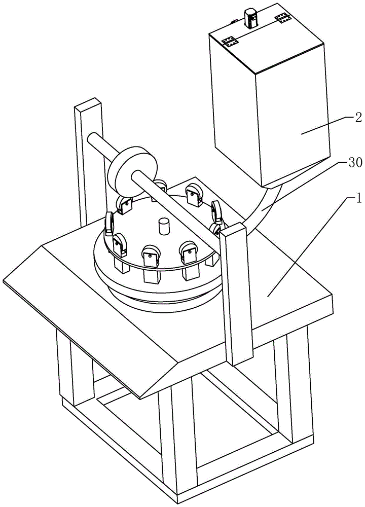
The present invention The present invention relates to the field of pharmaceutical equipment, in particular to a rotary tablet press, comprising a tablet press body and a lower hopper arranged on the tablet press body, wherein the lower hopper is provided with a preventer for dredging pharmaceutical raw materials A blocking device, the anti-blocking device includes a dredging member and a driving device for controlling the vertical and horizontal rotation of the dredging member. The present application improves the problem that pharmaceutical raw materials are easily blocked in the lower hopper, which affects the quality of the finished tablet.
Description
技术领域technical field
本发明涉及制药设备领域,尤其是涉及一种旋转式压片机。The invention relates to the field of pharmaceutical equipment, in particular to a rotary tablet press.
背景技术Background technique
在中药、饮片等行业中,压片机作为压片成型的主要设备,在制药设备领域中得到了广泛的应用。In the industries of traditional Chinese medicine and decoction pieces, tablet presses are widely used in the field of pharmaceutical equipment as the main equipment for tablet forming.
公告号为CN207626519U的中国专利公开了一种旋转式药片压片机,包括主机体以及设置在主机体上的压片机构,主机体的侧壁上可拆卸的设置有收集桶,收集桶的侧壁上设置有把手;压片机构包括上固定柱以及下固定柱,上固定柱上设置有第一压轮,上固定柱与下固定柱之间设置有转轴,转轴上依次设置有上旋转盘、中旋转盘以及下旋转盘,上旋转盘上呈环形排布有上冲杆;中旋转盘上呈环形排布有冲压孔,中旋转盘的上侧面设置有压盘,压盘上开设有料孔,压盘的内部开设有与料孔连通的下料通道,下料通道呈倾斜设置,下料通道的出料口与冲压孔连通;下旋转盘上呈环形排布有下冲压杆;下固定柱上设置有固定盘,固定盘上呈环形排布有滚针,固定盘的侧壁上设置有第二压轮,第二压轮穿过固定盘,并且第二压轮与第一压轮相互垂直设置,还包括下料斗,下料斗与压盘上的料孔连通。The Chinese patent with the publication number CN207626519U discloses a rotary tablet press, including a main body and a tablet pressing mechanism arranged on the main body. A handle is arranged on the wall; the tablet pressing mechanism includes an upper fixing column and a lower fixing column, a first pressing wheel is arranged on the upper fixing column, a rotating shaft is arranged between the upper fixing column and the lower fixing column, and an upper rotating disc is arranged on the rotating shaft in turn , the middle rotating plate and the lower rotating plate, the upper rotating plate is annularly arranged with upper punches; the middle rotating plate is annularly arranged with punching holes, the upper side of the middle rotating plate is provided with a pressure plate, and the pressure plate is provided with material The inside of the platen is provided with a feeding channel that communicates with the feeding hole, the feeding channel is inclined and the discharge port of the feeding channel is connected with the punching hole; the lower rotating plate is annularly arranged with lower punching rods; A fixed plate is arranged on the fixed column, needle rollers are arranged in a ring shape on the fixed plate, a second pressure wheel is arranged on the side wall of the fixed plate, the second pressure wheel passes through the fixed plate, and the second pressure wheel is connected with the first pressure wheel. The wheels are arranged perpendicular to each other, and also includes a lowering hopper, which is communicated with the material hole on the pressing plate.
上述压片机虽然能够实现压片的目的,但是在下料过程中,制药原料容易堵塞在下料斗内,导致进入到冲压孔内的制药原料不足,进而影响压片的成品质量。Although the above-mentioned tableting machine can achieve the purpose of tableting, during the blanking process, the pharmaceutical raw materials are easily blocked in the lowering hopper, resulting in insufficient pharmaceutical raw materials entering the punching holes, thereby affecting the quality of the finished tablet.
发明内容SUMMARY OF THE INVENTION
为了改善制药原料容易堵塞在下料斗内,影响压片成品质量的问题,本申请提供一种旋转式压片机。In order to improve the problem that the pharmaceutical raw materials are easily blocked in the lower hopper and affect the quality of the finished tablet, the present application provides a rotary tablet press.
本申请提供的一种旋转式压片机采用如下的技术方案:A rotary tablet press provided by the application adopts the following technical solutions:
一种旋转式压片机,包括压片机主体和设置在压片机主体上的下料斗,所述下料斗内设置有用于疏通制药原料的防堵装置,所述防堵装置包括疏通件、用于控制疏通件沿竖直方向转动和水平方向转动的驱动装置。A rotary tablet press comprises a tablet press main body and a lower hopper arranged on the tablet press body, the lower hopper is provided with an anti-blocking device for dredging pharmaceutical raw materials, the anti-blocking device comprises a dredging piece, A driving device for controlling the vertical and horizontal rotation of the dredging element.
通过采用上述技术方案,在进行下料操作时,启动驱动装置,驱动装置在工作状态下驱动疏通件在下料斗内沿竖直方向和水平方向转动,从而对下料斗内的制药原料进行疏通,减小制药原料堵塞在下料斗内,导致进入到冲压孔内的制药原料不足的可能性,减小压片的成品质量受到影响的可能性,改善了制药原料容易堵塞在下料斗内,影响压片成品质量的问题。By adopting the above technical solution, during the unloading operation, the drive device is activated, and the drive device drives the dredging member to rotate in the vertical and horizontal directions in the unloading hopper in the working state, thereby dredging the pharmaceutical raw materials in the unloading hopper, reducing the Small pharmaceutical raw materials are blocked in the lower hopper, resulting in the possibility of insufficient pharmaceutical raw materials entering the punching hole, reducing the possibility of affecting the quality of the finished tablet, improving the easy clogging of the pharmaceutical raw materials in the lower hopper, affecting the quality of the tablet finished product The problem.
可选的,所述驱动装置包括第一电机、第二电机、第一连接块、第二连接块和第一球头,第一电机和第二电机均设置在下料斗上,第一连接块连接在第一电机上,第一连接块上转动连接有转轴,转轴的一端连接疏通件,另一端连接第一球头,第一球头的中心与第一电机上电机轴的中心线重合,第二连接块设置在第二电机上,第二连接块上设有第二球头,第一球头上设有球接槽,第二球头通过球接槽滑动连接在第一球头上,第一电机的电机轴与第二电机的电机轴相互垂直,疏通件呈竖直状态时,第一球头和第二球头的中心位于同一水平线上,球接槽呈竖直状态。Optionally, the driving device includes a first motor, a second motor, a first connection block, a second connection block and a first ball head, the first motor and the second motor are both arranged on the lower hopper, and the first connection block is connected On the first motor, a rotating shaft is rotatably connected to the first connecting block, one end of the rotating shaft is connected to the dredging piece, and the other end is connected to the first ball head, the center of the first ball head coincides with the center line of the motor shaft on the first motor, Two connecting blocks are arranged on the second motor, the second connecting block is provided with a second ball joint, the first ball joint is provided with a ball joint groove, and the second ball joint is slidably connected to the first ball joint through the ball joint groove, The motor shaft of the first motor and the motor shaft of the second motor are perpendicular to each other. When the dredging member is in a vertical state, the centers of the first ball head and the second ball head are on the same horizontal line, and the ball joint groove is in a vertical state.
通过采用上述技术方案,启动第一电机,第一电机在工作状态下带动第一连接块、第一球头、转轴和疏通件转动,疏通件在转动过程中对制药原料进行搅动、疏通,当第一电机启动一定时间后,关闭第一电机,启动第二电机,第二电机带动第二连接块和第二球头转动,第二球头在转动过程中带动第一球头、转轴和疏通件转动,此时,疏通件的转动方向与第一电机驱动下疏通件的转动方向不同,从而能够从不同的方向对制药原料进行搅动、疏通的目的,疏通效果更好,进一步减小制药原料堵塞在下料斗内的可能性。By adopting the above technical solution, the first motor is started, and the first motor drives the first connecting block, the first ball head, the rotating shaft and the dredging member to rotate in the working state, and the dredging member stirs and dreds the pharmaceutical raw materials during the rotation process. After the first motor is started for a certain period of time, the first motor is turned off, and the second motor is started. The second motor drives the second connecting block and the second ball head to rotate, and the second ball head drives the first ball head, the rotating shaft and the dredging during the rotation process. At this time, the rotation direction of the dredging member is different from the rotation direction of the dredging member driven by the first motor, so that the pharmaceutical raw materials can be stirred and dredged from different directions, the dredging effect is better, and the pharmaceutical raw materials can be further reduced. Possibility of clogging in the lower hopper.
可选的,所述下料斗上设有辅助疏通装置,所述辅助疏通装置包括喷气嘴和喷气管,喷气嘴倾斜向下设置在下料斗侧壁上,喷气管设置在下料斗外部并连接喷气嘴。Optionally, an auxiliary dredging device is provided on the lower hopper, and the auxiliary dredging device includes an air nozzle and an air nozzle, the air nozzle is arranged on the side wall of the lower hopper obliquely downward, and the air nozzle is arranged outside the lower hopper and connected to the air nozzle.
通过采用上述技术方案,在加料过程中或者加料结束后,通过喷气管和喷气嘴向下料斗内喷吹高压气体,高压气体有助于将制药原料吹起,减小制药原料堆积在一起或者粘附在下料斗内壁上的可能性。By adopting the above technical solution, during the feeding process or after the feeding, the high-pressure gas is injected into the lower hopper through the jet pipe and the jet nozzle. The high-pressure gas helps to blow up the pharmaceutical raw materials and reduces the accumulation or sticking of the pharmaceutical raw materials. Possibility to attach to the inner wall of the lower hopper.
可选的,所述疏通件包括疏通主杆和疏通杆,疏通主杆通过连接杆连接在转轴上,疏通主杆的中心线与下料斗的中心线重合,疏通杆设置在疏通主杆上。Optionally, the dredging member includes a dredging main rod and a dredging rod, the dredging main rod is connected to the rotating shaft through a connecting rod, the center line of the dredging main rod coincides with the center line of the lower hopper, and the dredging rod is arranged on the dredging main rod.
通过采用上述技术方案,转轴通过连接杆与疏通主杆连接在一起,能够使驱动装置设置在下料斗的一侧,避免了向下料斗内加入制药原料的过程受到影响。By adopting the above technical solution, the rotating shaft is connected with the dredging main rod through the connecting rod, so that the driving device can be arranged on one side of the lower hopper, and the process of adding pharmaceutical raw materials into the lower hopper is avoided from being affected.
可选的,所述疏通主杆与疏通杆之间通过调节组件连接,调节组件包括调节杆、调节臂和第三球头,疏通主杆上设有槽口向上的安装槽,疏通主杆上设有连通安装槽的安装口,安装口连通疏通主杆外壁一端的开口小于安装口连通安装槽一端的开口,疏通杆铰接在安装口内,疏通杆的一端位于疏通主杆外,另一端位于疏通主杆内,调节杆滑动插设在安装槽内,疏通主杆上设有用于卡紧调节杆的卡紧件,所述调节臂设置在调节杆上,第三球头设置在调节臂上,疏通杆上设有调节槽,第三球头滑动连接在调节槽内。Optionally, the dredging main rod and the dredging rod are connected by an adjustment assembly, and the adjustment assembly includes an adjustment rod, an adjustment arm and a third ball head. There is an installation port that communicates with the installation groove. The opening of the outer wall of the main rod of the installation port is smaller than the opening of the installation port to the one end of the installation groove. The dredging rod is hinged in the installation port. In the main rod, the adjustment rod is slidably inserted into the installation groove, and a clamping piece for clamping the adjustment rod is arranged on the dredging main rod, the adjustment arm is arranged on the adjustment rod, and the third ball head is arranged on the adjustment arm, The dredging rod is provided with an adjustment groove, and the third ball head is slidably connected in the adjustment groove.
通过采用上述技术方案,使用者可以根据需求调节疏通杆的倾斜程度,调节时,先解除卡紧件对调节杆的卡紧,移动调节杆,改变调节杆和调节臂的位置,在调节臂移动过程中,第三球头与疏通杆之间的相对位置发生变化,从而改变疏通杆的倾斜程度,以便满足不同的使用需求。By adopting the above technical solution, the user can adjust the inclination of the dredging rod according to the needs. When adjusting, first release the clamping of the clamping member to the adjusting rod, move the adjusting rod, change the position of the adjusting rod and the adjusting arm, and move the adjusting arm when the adjusting rod is moved. During the process, the relative position between the third ball head and the unblocking rod changes, thereby changing the inclination of the unblocking rod, so as to meet different usage requirements.
可选的,所述卡紧件包括卡紧架和卡紧螺钉,卡紧架设置在疏通主杆上,卡紧螺钉穿设在卡紧架上,调节杆上沿调节杆的长度方向设有若干个卡紧螺纹孔,卡紧螺钉螺纹连接在卡紧螺纹孔内。Optionally, the clamping member includes a clamping frame and a clamping screw, the clamping frame is arranged on the dredging main rod, the clamping screw is penetrated on the clamping frame, and the adjusting rod is provided with a longitudinal direction of the adjusting rod. Several clamping threaded holes are provided, and the clamping screws are threadedly connected in the clamping threaded holes.
通过采用上述技术方案,拧动卡紧螺钉,使卡紧螺钉与调节杆分离,从而解除对调节杆的卡紧作用,将调节杆调节至适当位置后,再拧动卡紧螺钉,将卡紧螺钉重新螺纹连接在相应的卡紧螺纹孔内,快速完成对调节杆的卡紧,整个操作过程方便、快捷。By adopting the above technical solution, the clamping screw is twisted to separate the clamping screw from the adjustment rod, thereby releasing the clamping effect on the adjustment rod. The screw is re-threaded in the corresponding clamping threaded hole to quickly complete the clamping of the adjusting rod, and the entire operation process is convenient and fast.
可选的,所述安装槽内设有处于压缩状态的弹簧,弹簧的一端连接安装槽底部,另一端连接调节杆。Optionally, a spring in a compressed state is arranged in the installation groove, one end of the spring is connected to the bottom of the installation groove, and the other end is connected to the adjustment rod.
通过采用上述技术方案,在调节调节杆的过程中,当解除对调节杆的卡紧后,调节杆在弹簧的弹力作用下会自动弹出,不必工作人员去手动拉动,为工作人员调节调节杆的位置带来方便。By adopting the above technical solution, in the process of adjusting the adjusting rod, when the clamping of the adjusting rod is released, the adjusting rod will automatically pop up under the elastic force of the spring, and it is not necessary for the staff to manually pull the adjusting rod. The location brings convenience.
可选的,所述疏通主杆上设有用于封堵安装槽的封堵片,调节杆穿过封堵片。Optionally, the dredging main rod is provided with a blocking sheet for blocking the installation groove, and the adjusting rod passes through the blocking sheet.
通过采用上述技术方案,封堵片的设置能够将调节杆与安装槽槽口之间的缝隙遮挡,减小了制药原料进入到安装槽内的可能性。By adopting the above technical solution, the provision of the blocking sheet can block the gap between the adjustment rod and the slot of the installation slot, thereby reducing the possibility of pharmaceutical raw materials entering the installation slot.
综上所述,本申请包括以下至少一种有益技术效果:To sum up, the present application includes at least one of the following beneficial technical effects:
1.在进行下料操作时,启动驱动装置,驱动装置在工作状态下驱动疏通件在下料斗内沿竖直方向和水平方向转动,从而对下料斗内的制药原料进行疏通,减小制药原料堵塞在下料斗内,导致进入到冲压孔内的制药原料不足的可能性,减小压片的成品质量受到影响的可能性,改善了制药原料容易堵塞在下料斗内,影响压片成品质量的问题。1. During the unloading operation, start the drive device, and the drive device drives the dredging piece to rotate in the vertical and horizontal directions in the unloading hopper in the working state, so as to dredge the pharmaceutical raw materials in the unloading hopper and reduce the blockage of the pharmaceutical raw materials. In the lower hopper, the possibility of insufficient pharmaceutical raw materials entering the punching hole is reduced, the possibility of affecting the quality of the finished tablet is reduced, and the problem that the pharmaceutical raw material is easily blocked in the lower hopper and affects the quality of the tableted product is improved.
2.启动第一电机,第一电机在工作状态下带动第一连接块、第一球头、转轴和疏通件转动,疏通件在转动过程中对制药原料进行搅动、疏通,当第一电机启动一定时间后,关闭第一电机,启动第二电机,第二电机带动第二连接块和第二球头转动,第二球头在转动过程中带动第一球头、转轴和疏通件转动,此时,疏通件的转动方向与第一电机驱动下疏通件的转动方向不同,从而能够从不同的方向对制药原料进行搅动、疏通的目的,疏通效果更好,进一步减小制药原料堵塞在下料斗内的可能性。2. Start the first motor, the first motor drives the first connecting block, the first ball head, the rotating shaft and the dredging piece to rotate in the working state, and the dredging piece stirs and unclogs the pharmaceutical raw materials during the rotation process. When the first motor starts After a certain period of time, turn off the first motor and start the second motor. The second motor drives the second connecting block and the second ball head to rotate, and the second ball head drives the first ball head, the rotating shaft and the dredging piece to rotate during the rotation process. At the same time, the rotation direction of the dredging member is different from the rotation direction of the dredging member driven by the first motor, so that the pharmaceutical raw materials can be stirred and dredged from different directions, the dredging effect is better, and the blocking of pharmaceutical raw materials in the lower hopper can be further reduced. possibility.
3.使用者可以根据需求调节疏通杆的倾斜程度,调节时,先解除卡紧件对调节杆的卡紧,移动调节杆,改变调节杆和调节臂的位置,在调节臂移动过程中,第三球头与疏通杆之间的相对位置发生变化,从而改变疏通杆的倾斜程度,以便满足不同的使用需求。3. The user can adjust the inclination of the dredging rod according to the needs. When adjusting, first release the clamping of the clamping piece to the adjusting rod, move the adjusting rod, and change the position of the adjusting rod and the adjusting arm. During the movement of the adjusting arm, the first The relative position between the three-ball head and the unblocking rod changes, thereby changing the inclination of the unblocking rod to meet different usage requirements.
附图说明Description of drawings
图1是实施例1中用于体现旋转式压片机的结构示意图。FIG. 1 is a schematic structural diagram for embodying a rotary tablet press in Example 1. FIG.
图2是实施例1中用于体现防堵装置与下料斗之间位置关系的结构示意图。FIG. 2 is a schematic structural diagram used to represent the positional relationship between the anti-blocking device and the lower hopper in
图3是图2中的A部放大图。FIG. 3 is an enlarged view of part A in FIG. 2 .
图4是图2中的B部放大图。FIG. 4 is an enlarged view of part B in FIG. 2 .
图5是实施例1中用于体现调节组件的结构示意图。FIG. 5 is a schematic structural diagram for embodying the adjustment assembly in
图6是实施例2中用于体现喷气管与下料斗之间位置关系的结构示意图。FIG. 6 is a schematic structural diagram for showing the positional relationship between the air jet pipe and the lower hopper in
图7是实施例2中用于体现喷气嘴与疏通件之间位置关系的结构示意图。FIG. 7 is a schematic structural diagram for illustrating the positional relationship between the air nozzle and the dredging member in
附图标记说明:Description of reference numbers:
1、压片机主体;2、下料斗;3、第一电机;4、第二电机;5、第一连接块;6、第二连接块;7、第一球头;8、转轴;9、连接杆;10、安装板;11、盖板;12、第二球头;13、球接槽;14、疏通主杆;15、疏通杆;16、调节杆;17、调节臂;18、第三球头;19、安装槽;20、安装口;21、弹簧;22、封堵片;23、卡紧架;24、卡紧螺钉;25、卡紧螺纹孔;26、调节槽;27、喷气嘴;28、喷气管;29、封堵块;30、导料斜管;31、中间杆。1. Main body of tablet press; 2. Lower hopper; 3. First motor; 4. Second motor; 5. First connecting block; 6. Second connecting block; 7. First ball head; 8. Rotating shaft; 9 , connecting rod; 10, mounting plate; 11, cover plate; 12, second ball head; 13, ball joint groove; 14, dredging the main rod; 15, dredging rod; 16, adjusting rod; 17, adjusting arm; 18, The third ball head; 19, installation slot; 20, installation port; 21, spring; 22, blocking piece; 23, clamping frame; 24, clamping screw; 25, clamping threaded hole; 26, adjusting slot; 27 , Air jet nozzle; 28, Air jet pipe; 29, Blocking block; 30, Material guide inclined pipe; 31, Intermediate rod.
具体实施方式Detailed ways
本申请实施例公开一种旋转式压片机 。The embodiment of the present application discloses a rotary tablet press.
实施例1Example 1
参照图1,旋转式压片机包括压片机主体1和设置在压片机主体1上的下料斗2,下料斗2与压片机主体1之间通过导料斜管30连接,下料斗2底部呈漏斗状设置,以便顺利下料,下料斗2内设置有防堵装置,用于疏通制药原料,减小制药原料堵塞在下料斗2内的可能性。1, the rotary tablet press includes a
参照图1和图2,防堵装置包括疏通件和驱动装置,驱动用于控制疏通件沿竖直方向转动和水平方向转动。驱动装置包括第一电机3、第二电机4、第一连接块5、第二连接块6和第一球头7。1 and 2 , the blocking prevention device includes a dredging member and a driving device, and the driving device is used to control the rotation of the dredging member in a vertical direction and a horizontal direction. The driving device includes a
参照图2,第一电机3设置在下料斗2外侧壁上,第一电机3的电机轴穿过下料斗2侧壁连接第一连接块5,第一连接块5为L形,第一连接块5上转动连接有转轴8,转轴8贯穿第一连接块5,转轴8的一端连接有连接杆9,另一端连接第一球头7,连接杆9远离转轴8的一端连接疏通件,第一球头7的中心与第一电机3上电机轴的中心线重合。2, the
参照图2和图3,第二电机4通过安装板10设置在下料斗2上,安装板10连接在下料斗2斗口的一侧,安装板10上还铰接有用于遮挡下料斗2斗口剩余部分的盖板11,盖板11搭设在下料斗2上,第二电机4连接在安装板10上,第二电机4的电机轴穿过安装板10连接第二连接块6,第二连接块6为L形,第二连接块6上通过中间杆31连接有第二球头12,第一球头7上设有球接槽13,第二球头12通过球接槽13滑动连接在第一球头7上,第一球头7的中心与第二球头12的中心在同一水平线上,第一电机3的电机轴与第二电机4的电机轴相互垂直,第一电机3的电机轴水平设置,第二电机4的电机轴竖直设置。疏通件呈竖直状态时,球接槽13呈竖直状态。2 and 3, the second motor 4 is installed on the
在需要疏通下料斗2内的制药原料时,启动第一电机3,第一电机3在工作状态下带动第一连接块5转动,第一连接块5带动转轴8转动,转轴8带动与其相连的第一球头7和连接杆9转动,连接杆9带动疏通件转动,疏通件在转动过程中对制药原料进行搅动、疏通。When it is necessary to clear the pharmaceutical raw materials in the
当第一电机3启动一定时间后,关闭第一电机3,启动第二电机4,第二电机4通过第二连接块6带动第二球头12转动,第二球头12在转动过程中带动第一球头7转动,第一球头7通过转轴8和连接杆9带动疏通件转动,此时,疏通件的转动方向与第一电机3驱动下疏通件的转动方向不同,从而能够从不同的方向对制药原料进行搅动、疏通的目的。通过控制第一电机3和第二电机4的正反转,可以控制疏通件的转动方向,有助于提高疏通效果。After the
参照图2、图4和图5,疏通件包括疏通主杆14和疏通杆15,疏通主杆14连接在连接杆9上,初始时,疏通主杆14的中心线与下料斗2的中心线重合,疏通杆15设置在疏通主杆14上,具体的,疏通主杆14与疏通杆15之间通过调节组件连接,调节组件包括调节杆16、调节臂17和第三球头18。2, 4 and 5, the dredging member includes a dredging
参照图2、图4和图5,疏通主杆14上设有槽口向上的安装槽19,疏通主杆14侧壁上设有连通安装槽19的安装口20,安装口20连通疏通主杆14外壁一端的开口小于安装口20连通安装槽19一端的开口,安装口20上竖直方向上相对的两个侧壁朝向相互远离方向倾斜。疏通杆15铰接在安装口20内,疏通杆15的一端位于疏通主杆14外,另一端位于疏通主杆14内。Referring to Figure 2, Figure 4 and Figure 5, the dredging
参照图2、图3和图4,调节杆16滑动插设在安装槽19内,安装槽19内连接有处于压缩状态的弹簧21,弹簧21的一端连接安装槽19底部,另一端连接调节杆16,疏通主杆14上连接有用于封堵安装槽19的封堵片22,调节杆16可滑动穿过封堵片22,疏通主杆14上还连接有卡紧件,当调节杆16调节至适当位置后,用于卡紧调节杆16,卡紧件包括卡紧架23和卡紧螺钉24,卡紧架23设置在封堵片22上,卡紧螺钉24穿设在卡紧架23上,调节杆16上沿调节杆16的长度方向设有若干个卡紧螺纹孔25,卡紧螺钉24螺纹连接在卡紧螺纹孔25内。2 , 3 and 4 , the
参照图4和图5,调节臂17设置在调节杆16上,调节臂17为L形,调节臂17的一端连接调节杆16,另一端连接第三球头18,疏通杆15上设有调节槽26,第三球头18滑动连接在调节槽26内,调节槽26为T形槽,疏通杆15靠近调节杆16的一端连接有用于封堵调节槽26的封堵块29,避免第三球头18从调节槽26内脱离。4 and 5, the adjusting
使用者可以根据需求调节疏通杆15的倾斜程度,在调节时,打开盖板11,转动卡紧螺钉24,将卡紧螺钉24从卡紧螺纹孔25内旋出,解除对调节杆16的卡紧,调节杆16在弹簧21的弹力作用下发生移动,调节杆16朝向远离弹簧21方向移动,使用者再根据需求按压调节杆16,使调节杆16移动,改变调节杆16和调节臂17的位置,在调节臂17移动过程中,第三球头18随着调节臂17一起移动,从而使第三球头18与疏通杆15之间的相对位置发生变化,从而改变疏通杆15的倾斜程度,以便满足不同的使用需求。The user can adjust the inclination of the
本申请实施例1的实施原理为:在向下料斗2内加入制药原料前,打开盖板11,使用者先根据需求调节疏通杆15的倾斜程度,将疏通杆15的倾斜程度调节好之后,向下料斗2内加入制药原料,与此同时,启动第一电机3或者第二电机4,使疏通件发生转动,疏通件转动过程中对制药原料进行搅动、疏通,且第一电机3和第二电机4交替启动,可以使疏通件从不同的方向进行搅动、疏通,减小制药原料堵塞在下料斗2内,导致进入到冲压孔内的制药原料不足的可能性,减小压片的成品质量受到影响的可能性,改善了制药原料容易堵塞在下料斗2内,影响压片成品质量的问题。The implementation principle of Example 1 of the present application is as follows: before adding pharmaceutical raw materials into the
实施例2Example 2
参照图6和图7,与实施例1的不同之处在于,下料斗2外侧壁上连接有辅助疏通装置,辅助疏通装置包括喷气嘴27和喷气管28,喷气嘴27倾斜向下设置在下料斗2侧壁上,喷气管28设置在下料斗2外部并连接喷气嘴27,喷气嘴27位于下料斗2内的一端与疏通件之间留有空隙,避免疏通件的转动受到影响。6 and 7, the difference from
本申请实施例2的实施原理为:可向喷气管28内注入高压气体,高压气体通过喷气嘴27喷吹,高压气体将制药原料吹起,减小制药原料堆积在一起或者粘附在下料斗2内壁上的可能性,喷气管28与防堵装置配合使用,有助于解决制药原料容易堵塞在下料斗2内的问题。The implementation principle of the second embodiment of the present application is as follows: the high-pressure gas can be injected into the
Claims (8)
Priority Applications (1)
| Application Number | Priority Date | Filing Date | Title |
|---|---|---|---|
| CN202210452071.XA CN114986977A (en) | 2022-04-27 | 2022-04-27 | Rotary Tablet Press |
Applications Claiming Priority (1)
| Application Number | Priority Date | Filing Date | Title |
|---|---|---|---|
| CN202210452071.XA CN114986977A (en) | 2022-04-27 | 2022-04-27 | Rotary Tablet Press |
Publications (1)
| Publication Number | Publication Date |
|---|---|
| CN114986977A true CN114986977A (en) | 2022-09-02 |
Family
ID=83026258
Family Applications (1)
| Application Number | Title | Priority Date | Filing Date |
|---|---|---|---|
| CN202210452071.XA Pending CN114986977A (en) | 2022-04-27 | 2022-04-27 | Rotary Tablet Press |
Country Status (1)
| Country | Link |
|---|---|
| CN (1) | CN114986977A (en) |
Citations (6)
| Publication number | Priority date | Publication date | Assignee | Title |
|---|---|---|---|---|
| WO2018033046A1 (en) * | 2016-08-18 | 2018-02-22 | 杨健勃 | Universal ball joint, module installed with said universal ball joint and component connection method |
| CN209291164U (en) * | 2018-11-20 | 2019-08-23 | 苏州市江远热电有限责任公司 | One plant feed bin preventing plug dredging device |
| CN212097680U (en) * | 2020-04-20 | 2020-12-08 | 江苏颐海药业有限责任公司 | Reinforced preforming structure of rotary tablet press |
| CN213353657U (en) * | 2020-09-01 | 2021-06-04 | 杭州万邦天诚药业有限公司 | Pharmacy tablet press blowing bucket of easy installation |
| CN215086145U (en) * | 2020-12-30 | 2021-12-10 | 山东皓尊生物科技有限公司 | Leather auxiliary agent exhaust treatment device |
| CN215918536U (en) * | 2021-07-26 | 2022-03-01 | 安徽中天石化股份有限公司 | Laboratory is with simple and easy electronic big round flask belt cleaning device |
-
2022
- 2022-04-27 CN CN202210452071.XA patent/CN114986977A/en active Pending
Patent Citations (6)
| Publication number | Priority date | Publication date | Assignee | Title |
|---|---|---|---|---|
| WO2018033046A1 (en) * | 2016-08-18 | 2018-02-22 | 杨健勃 | Universal ball joint, module installed with said universal ball joint and component connection method |
| CN209291164U (en) * | 2018-11-20 | 2019-08-23 | 苏州市江远热电有限责任公司 | One plant feed bin preventing plug dredging device |
| CN212097680U (en) * | 2020-04-20 | 2020-12-08 | 江苏颐海药业有限责任公司 | Reinforced preforming structure of rotary tablet press |
| CN213353657U (en) * | 2020-09-01 | 2021-06-04 | 杭州万邦天诚药业有限公司 | Pharmacy tablet press blowing bucket of easy installation |
| CN215086145U (en) * | 2020-12-30 | 2021-12-10 | 山东皓尊生物科技有限公司 | Leather auxiliary agent exhaust treatment device |
| CN215918536U (en) * | 2021-07-26 | 2022-03-01 | 安徽中天石化股份有限公司 | Laboratory is with simple and easy electronic big round flask belt cleaning device |
Similar Documents
| Publication | Publication Date | Title |
|---|---|---|
| CN105059939B (en) | A kind of Dosed medicinal powder feeding device | |
| CN207789406U (en) | A kind of feeding mechanism of vacuum kneader | |
| JPH0899199A (en) | Rotating disk unit cleaning device for rotary powder compression molding machine | |
| CN212018366U (en) | An automatic grouting machine | |
| CN207088430U (en) | A kind of Intelligent injection machine tool hand injection moulding apparatus | |
| CN112873622B (en) | Degradable hot melt pressure sensitive adhesive production filter equipment | |
| CN215556635U (en) | A sugar-dissolving tank for candy production | |
| CN218715186U (en) | Multi-angle pouring mechanism | |
| CN111438992A (en) | Non-woven bag tapping machine | |
| CN111851494A (en) | A concrete seeding machine for low wall with bottom plate | |
| CN217417124U (en) | Anti-tearing water stop production feeder | |
| CN212312856U (en) | A kind of getter tablet pressing device for thermos cup | |
| JPH04259689A (en) | Linear pump | |
| CN216068423U (en) | Feeding device of injection molding machine | |
| CN212097680U (en) | Reinforced preforming structure of rotary tablet press | |
| CN115464004A (en) | A flat steel straightening equipment for civil air defense door processing | |
| CN115584733A (en) | Pile foundation is hopper guiding device for concrete placement | |
| CN111655468A (en) | Adjustable initial pressure rail for rotary presses with integrated measurement of initial pressure | |
| CN119460267B (en) | A high-efficiency vacuum vertical packaging machine | |
| CN115672162A (en) | Raw material mixing equipment | |
| CN223452762U (en) | Chocolate pouring equipment | |
| CN222998848U (en) | A feeding device convenient for roller press control | |
| CN219902680U (en) | Concrete scattering and distributing device | |
| CN219618235U (en) | Leakage-proof device for chemical medicine in tyre production | |
| CN206015249U (en) | A kind of direct-drive type intermittent presser foot of sewing machine |
Legal Events
| Date | Code | Title | Description |
|---|---|---|---|
| PB01 | Publication | ||
| PB01 | Publication | ||
| SE01 | Entry into force of request for substantive examination | ||
| SE01 | Entry into force of request for substantive examination | ||
| RJ01 | Rejection of invention patent application after publication |
Application publication date: 20220902 |
|
| RJ01 | Rejection of invention patent application after publication |