CN114940524A - A waste liquid recovery recycles device for hexafluorobutadiene production - Google Patents
A waste liquid recovery recycles device for hexafluorobutadiene production Download PDFInfo
- Publication number
- CN114940524A CN114940524A CN202210605108.8A CN202210605108A CN114940524A CN 114940524 A CN114940524 A CN 114940524A CN 202210605108 A CN202210605108 A CN 202210605108A CN 114940524 A CN114940524 A CN 114940524A
- Authority
- CN
- China
- Prior art keywords
- waste liquid
- fixedly connected
- gear
- rod
- groove
- Prior art date
- Legal status (The legal status is an assumption and is not a legal conclusion. Google has not performed a legal analysis and makes no representation as to the accuracy of the status listed.)
- Granted
Links
Images


Classifications
-
- C—CHEMISTRY; METALLURGY
- C02—TREATMENT OF WATER, WASTE WATER, SEWAGE, OR SLUDGE
- C02F—TREATMENT OF WATER, WASTE WATER, SEWAGE, OR SLUDGE
- C02F1/00—Treatment of water, waste water, or sewage
- C02F1/28—Treatment of water, waste water, or sewage by sorption
-
- C—CHEMISTRY; METALLURGY
- C02—TREATMENT OF WATER, WASTE WATER, SEWAGE, OR SLUDGE
- C02F—TREATMENT OF WATER, WASTE WATER, SEWAGE, OR SLUDGE
- C02F2101/00—Nature of the contaminant
- C02F2101/30—Organic compounds
- C02F2101/36—Organic compounds containing halogen
-
- C—CHEMISTRY; METALLURGY
- C02—TREATMENT OF WATER, WASTE WATER, SEWAGE, OR SLUDGE
- C02F—TREATMENT OF WATER, WASTE WATER, SEWAGE, OR SLUDGE
- C02F2103/00—Nature of the water, waste water, sewage or sludge to be treated
- C02F2103/34—Nature of the water, waste water, sewage or sludge to be treated from industrial activities not provided for in groups C02F2103/12 - C02F2103/32
- C02F2103/36—Nature of the water, waste water, sewage or sludge to be treated from industrial activities not provided for in groups C02F2103/12 - C02F2103/32 from the manufacture of organic compounds
Abstract
The invention is suitable for the technical field of production of hexafluorobutadiene, and provides a waste liquid recycling device for producing hexafluorobutadiene, which comprises a recycling pipeline, wherein a water inlet pipe and a water outlet pipe are fixedly arranged at two ends of the recycling pipeline through bolts, blocking mechanisms for blocking the flow of the waste liquid are arranged inside the water inlet pipe and the water outlet pipe, each blocking mechanism comprises a closing component and a driving component, an article placing groove is fixedly connected to the top of the outer wall of the recycling pipeline, a plurality of adsorption blocks are placed inside the article placing groove, the waste liquid can pass through the adsorption blocks inside the recycling pipeline in the process of flowing inside the recycling pipeline, and can be subjected to preliminary adsorption treatment under the action of the adsorption blocks, so that the dirt in the waste liquid can be reduced, the material dosage used for subsequent waste liquid treatment can be reduced, and the problem that the waste liquid cannot be completely treated due to partial dirt is prevented, meanwhile, the waste liquid treatment efficiency is improved.
Description
Technical Field
The invention relates to the field of production of hexafluorobutadiene, in particular to a waste liquid recycling device for production of hexafluorobutadiene.
Background
In the synthetic production of the hexafluorobutadiene, the product hexafluorobutadiene is gaseous at normal temperature and normal pressure, a reaction system formed by reactants, reaction products and solvents often contains a mixture of two or more phases, waste liquid mixed with pure water is generated in the production process of the hexafluorobutadiene, and the generated waste liquid needs to be recycled.
Therefore, the direct discharge of the waste liquid of the hexafluorobutadiene not only causes the problem of material waste, but also causes the situation that the filter device for the waste liquid of the hexafluorobutadiene cannot be replaced in time.
Therefore, it is required to provide a waste liquid recycling apparatus for producing hexafluorobutadiene, aiming at solving the above problems.
Disclosure of Invention
Aiming at the defects in the prior art, the embodiment of the invention aims to provide a waste liquid recycling device for producing hexafluorobutadiene, and aims to overcome the defects that reaction materials are wasted due to direct discharge of the waste liquid of the hexafluorobutadiene and a device for treating the hexafluorobutadiene waste liquid in equipment cannot be replaced in time.
In order to achieve the purpose, the invention provides the following technical scheme:
the utility model provides a waste liquid recovery recycles device for hexafluorobutadiene production, includes the recovery pipeline, the both ends of recovery pipeline all have inlet tube and outlet pipe through bolt fixed mounting, the inside of inlet tube and outlet pipe all is provided with the separation mechanism that is used for blocking the waste liquid flow, separation mechanism includes closed subassembly and drive assembly, the outer wall top fixedly connected with of recovery pipeline puts the thing groove, put the inside in thing groove and placed a plurality of adsorption blocks, the outer wall outside fixedly connected with collecting vat of recovery pipeline, the bottom joint of collecting vat has the collection box that is used for collecting the adsorption block, the outer wall outside fixedly connected with boss of recovery pipeline, the inboard of boss is provided with the reciprocal subassembly that is used for promoting the adsorption block, the inboard fixed joint of reciprocal subassembly has the push pedal that is used for promoting the adsorption block, be provided with the supporting component that is used for supporting the adsorption block on the push pedal, the inside of recovery pipeline is provided with the current-limiting subassembly that is used for controlling the waste liquid and flows, the inside of recovery pipeline is provided with the control assembly that is used for detecting the velocity of flow.
As a further scheme of the invention, the closing assembly comprises a rotating groove, a fixed pipeline, a rotating gear ring, a guide groove, a leaf plate and a guide rod, the rotating groove for rotating the rotating gear ring is formed in the water outlet pipe, the fixed pipeline is fixedly connected to the inside of the recovery pipeline through a bolt, the rotating gear ring is rotatably connected to the outer wall of the fixed pipeline, the guide groove for driving the guide rod to move is formed in the outer wall of the rotating gear ring, the leaf plate is rotatably connected to the outer wall of the fixed pipeline through the rotating rod, the guide rod is fixedly connected to the inner side of the leaf plate, and the guide rod is movably connected to the inside of the guide groove.
As a further scheme of the present invention, the driving assembly includes a rotation hole, a first fixing seat, a rotation shaft, a first gear, a second gear, a rotation gear ring, a second fixing seat, a first motor and a third gear, the outer wall of the water outlet pipe is provided with a rotation hole for rotation of the rotation shaft, the first fixing seat is fixedly installed on the outer wall of the water outlet pipe, the rotation shaft is rotatably connected to the outer side of the first fixing seat, the inner side of the first gear is engaged with the outer wall of the rotation gear ring, the first gear is fixedly connected to one end of the rotation shaft, one end of the rotation shaft is fixedly connected with the second gear for transmission, the outer side of the second gear is engaged with the inner side of the rotation gear ring, the first motor is fixedly installed on the top of the water outlet pipe through the second fixing seat, the output end of the first motor is fixedly connected with the third gear for transmission, the bottom of the third gear is meshed with the top of the rotating gear ring.
As a further scheme of the invention, the reciprocating assembly comprises a hydraulic telescopic rod and a push rod, the interior of the boss is fixedly connected with the hydraulic telescopic rod for driving, the output end of the hydraulic telescopic rod is fixedly connected with the push rod for reciprocating pushing, the push plate is fixedly connected to the inner side of the push rod, and the push plate is movably connected to the interior of the recovery pipeline.
As a further scheme of the invention, the supporting component comprises a first movable groove and a supporting rod, the first movable groove for the supporting rod to move is formed in the boss, the supporting rod is fixedly connected to the top of the push plate, and the supporting rod is movably connected to the inside of the supporting rod.
As a further scheme of the invention, the flow limiting assembly comprises a stabilizer bar, a first spring and a water control plate, the interior of the recovery pipeline is fixedly connected with the stabilizer bar for stable movement, the inner wall of the recovery pipeline is fixedly connected with one end of the first spring, the other end of the first spring is fixedly connected with the water control plate for waste liquid flow limiting, and the water control plate is movably connected with the interior of the stabilizer bar.
As a further scheme of the invention, the control assembly comprises a second movable groove, an electric contact rod, a second spring, a contact plate, a fixed block, an electric contact groove and a contact sleeve, the second movable groove for movement is formed in the recovery pipeline, the electric contact rod for circuit control is fixedly connected to the inside of the second movable groove, the second spring is fixedly connected to the inside of the second movable groove, the contact plate is fixedly connected to the bottom of the second spring, the fixed block is fixedly connected to the upper surface of the contact plate, the electric contact groove for circuit control is formed in the top of the fixed block, and the electric contact groove for contact with the waste liquid is fixedly connected to the bottom of the second movable groove.
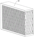
As a further scheme of the invention, a plurality of layers of adsorption materials are arranged inside the adsorption block, and the adsorption block is matched with the storage tank, the collecting tank and the collecting box in size.
As a further scheme of the invention, the first motor and the hydraulic telescopic rod are both electrically connected with the electric contact groove, and the electric contact rod is electrically connected with the equipment use power supply.
Compared with the prior art, the waste liquid recycling device for producing the hexafluorobutadiene, provided by the invention, has the beneficial effects that:
1. in the process that the waste liquid flows in the recovery pipeline, the waste liquid can pass through the adsorption block in the recovery pipeline, so that the waste liquid can be subjected to preliminary adsorption treatment under the action of the adsorption block, dirt in the waste liquid can be reduced, the material dosage used in subsequent waste liquid treatment can be reduced, the problem that the waste liquid cannot be completely treated due to partial dirt is prevented, and the waste liquid treatment efficiency is improved;
2. the hydraulic telescopic rod is controlled to be electrified and then stretched to drive the push rod to move towards the inner side, the push rod drives the push plate to move towards the inner side, the push plate pushes the adsorption block towards the inner part of the collecting tank, and then the hydraulic telescopic rod is controlled to be contracted to enable the push rod to drive the push plate to move towards the outer side;
3. in the process that the push plate moves towards the inner side, the push plate drives the supporting rod to move towards the inner side in the first movable groove, and when the push plate pushes the adsorption block to move to the innermost side of the collection groove, the supporting rod can prevent the problem that the adsorption block at the top of the storage groove falls to cause the internal mechanism to be clamped by the adsorption block, so that the smoothness of equipment operation is improved, and the normal operation of the equipment is ensured;
4. the first motor is electrified to drive the third gear at the output end of the first motor to rotate, the third gear drives the rotating gear ring to rotate, the rotating gear ring drives the second gear which is meshed with the rotating gear ring to rotate, the second gear drives the first gear to rotate in the rotating groove through the rotating shaft which rotates on the first fixing seat, the first gear drives the rotating gear ring which is meshed with the inner side of the first gear ring to rotate, the rotating gear ring enables the fan blade plate to rotate inwards by taking the rotating rod as an axis under the interaction of the guide groove and the guide rod, so that the fan blade plate blocks a fixed pipeline, flowing waste liquid is blocked, a stable environment is provided for subsequent replacement of the adsorption block, the flowing waste liquid is prevented from causing the equipment to be inconvenient for replacement of the adsorption block, and the replacement efficiency of the subsequent adsorption block is improved;
5. through the in-process that the waste liquid flows, waste liquid and the contact of accuse water board can carry out the current-limiting to the waste liquid under the effect of accuse water board, and then reduce because the too big erosive wear that leads to the inside equipment to cause of waste liquid velocity of flow, and then improve equipment's life.
To more clearly illustrate the structural features and effects of the present invention, the present invention will be described in detail below with reference to the accompanying drawings and specific embodiments.
Drawings
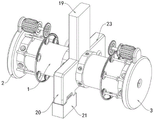
FIG. 1 is a perspective view of the overall structure of the present invention;
FIG. 2 is a schematic side view of the overall structure of the present invention;
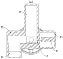
FIG. 3 is a schematic cross-sectional view of the structure A-A of FIG. 2 according to the present invention;
FIG. 4 is a perspective view of the internal structure of the present invention;
FIG. 5 is a perspective view of the reciprocating assembly and the supporting assembly of the present invention;
FIG. 6 is a perspective view of the relationship between the closing element and the adsorbing block;
FIG. 7 is an enlarged view of the structure at A in FIG. 6 according to the present invention;
FIG. 8 is an enlarged view of the structure at B in FIG. 6 according to the present invention;
FIG. 9 is a perspective view of the positional relationship between the closing assembly and the outlet pipe of the present invention;
FIG. 10 is a perspective view of the overall construction of the closure assembly of the present invention;
fig. 11 is a perspective view of the internal structure of the adsorption block of the present invention.
Reference numerals: 1. a recovery pipeline; 2. a water inlet pipe; 3. a water outlet pipe; 4. a rotating groove; 5. fixing the pipeline; 6. rotating the gear ring; 7. a guide groove; 8. a leaf plate; 9. a guide bar; 10. rotating the hole; 11. a first fixed seat; 12. a rotating shaft; 13. a first gear; 14. a second gear; 15. rotating the toothed ring; 16. a second fixed seat; 17. a first motor; 18. a third gear; 19. a storage groove; 20. collecting tank; 21. a collection box; 22. an adsorption block; 23. a boss; 24. a hydraulic telescopic rod; 30. a push rod; 31. pushing the plate; 32. a first movable slot; 33. a support bar; 34. a stabilizer bar; 35. a first spring; 36. a water control plate; 37. a second movable slot; 38. an electrical contact bar; 39. a second spring; 40. a contact plate; 41. a fixed block; 42. an electric contact groove; 43. and a contact sleeve.
Detailed Description
In order to make the objects, technical solutions and advantages of the present invention more apparent, the present invention is described in further detail below with reference to the accompanying drawings and embodiments. It should be understood that the specific embodiments described herein are merely illustrative of the invention and are not intended to limit the invention.
In the description of the present invention, the terms "center", "lateral", "upper", "lower", "left", "right", "vertical", "horizontal", "top", "bottom", "inner", "outer", etc., indicate orientations or positional relationships based on the orientations or positional relationships shown in the drawings, and are only for convenience in describing the present invention and simplifying the description, but do not indicate or imply that the device or element being referred to must have a particular orientation, be constructed and operated in a particular orientation, and thus, should not be construed as limiting the present invention.
Specific implementations of the present invention are described in detail below with reference to specific embodiments.
Example one
As shown in fig. 1 and 11, a waste liquid recycling apparatus for producing hexafluorobutadiene according to an embodiment of the present invention includes a recycling pipeline 1, a water inlet pipe 2 and a water outlet pipe 3 are fixedly installed at both ends of the recycling pipeline 1 through bolts, a blocking mechanism for blocking the flow of waste liquid is installed inside each of the water inlet pipe 2 and the water outlet pipe 3, the blocking mechanism includes a closing component and a driving component, an article placing groove 19 is fixedly connected to the top of the outer wall of the recycling pipeline 1, a plurality of adsorbing materials are arranged inside the article placing groove 19, a plurality of layers of adsorbing materials are arranged inside the adsorbing blocks 22, the adsorbing blocks 22 are matched with the article placing groove 19, the collecting groove 20 and the collecting box 21 in size, a collecting groove 20 is fixedly connected to the outer side of the outer wall of the recycling pipeline 1, a collecting box 21 for collecting the adsorbing blocks 22 is clamped to the bottom of the collecting groove 20, a boss 23 is fixedly connected to the outer side of the outer wall of the recycling pipeline 1, the inboard of boss 23 is provided with the reciprocal subassembly that is used for promoting adsorption block 22, and the inboard fixed joint of reciprocal subassembly has the push pedal 31 that is used for promoting adsorption block 22, is provided with the supporting component who is used for supporting adsorption block 22 on the push pedal 31, and the inside of recovery pipeline 1 is provided with the current-limiting subassembly that is used for controlling the waste liquid flow, and the inside of recovery pipeline 1 is provided with the control assembly that is used for detecting the velocity of flow.
Preferably, in an embodiment of the present invention, during operation, the waste liquid flows into the interior of the recovery pipeline 1 through the water inlet pipe 2, and flows out of the water outlet pipe 3 through the water inlet pipe 2, while the waste liquid flows in the interior of the recovery pipeline 1, the waste liquid passes through the adsorption block 22, the waste liquid can be primarily treated by adsorption of the adsorption block 22, during a normal flow rate of the waste liquid, the flow limiting component is pushed to be unable to contact with the control component, and then is in a normal flow state, when too much waste liquid dirt is adsorbed on the adsorption block 22, the flow rate of the waste liquid is slowed down, at this time, the flow limiting component contacts with the control component, and then the control component makes the reciprocating component and the driving component move, after the driving component moves, the closing component is closed, so that the waste liquid stops flowing, at this time, the reciprocating component drives the push plate 31 to push the adsorption block 22 to move towards the interior of the collection tank 20, simultaneously can prevent to put the inside absorption piece 22 of thing groove 19 and drop the inside of recovery pipeline 1 under supporting component's effect, after push pedal 31 moves to boss 23 under reciprocating assembly's effect, push pedal 31 drives supporting component and can't support the inside absorption piece 22 of thing groove 19 to boss 23 motion this moment, put the inside absorption piece 22 of thing groove 19 and make absorption piece 22 drop the inside of recovery pipeline 1 under the effect of gravity, and then accomplish the effect of changing absorption piece 22, absorption piece 22 has been improved and has been tentatively adsorbed filtration efficiency to the waste liquid, make closed subassembly open under the control action of equipment this moment after accomplishing the change, the waste liquid continues to flow to treatment process on next step through recovery pipeline 1.
Example two
As shown in fig. 5, 6 and 7, as a preferred embodiment of the present invention, the current limiting assembly includes a stabilizer bar 34, a first spring 35 and a water control plate 36, the interior of the recovery pipe 1 is fixedly connected with the stabilizer bar 34 for stabilizing movement, the inner wall of the recovery pipe 1 is fixedly connected with one end of the first spring 35, the other end of the first spring 35 is fixedly connected with the water control plate 36 for limiting the flow of waste liquid, and the water control plate 36 is movably connected with the interior of the stabilizer bar 34.
The control assembly comprises a second movable groove 37, an electric contact rod 38, a second spring 39, a contact plate 40, a fixed block 41, an electric contact groove 42 and a contact sleeve 43, the second movable groove 37 used for moving is formed in the recycling pipeline 1, the electric contact rod 38 used for circuit control is fixedly connected to the inside of the second movable groove 37, the electric contact rod 38 is electrically connected with a power supply used by equipment, the second spring 39 is fixedly connected to the inside of the second movable groove 37, the contact plate 40 is fixedly connected to the bottom of the second spring 39, the fixed block 41 is fixedly connected to the upper surface of the contact plate 40, the electric contact groove 42 used for circuit control is formed in the top of the fixed block 41, and the electric contact groove 42 used for being in contact with waste liquid is fixedly connected to the bottom of the second movable groove 37.
Preferably, in this embodiment, when the amount of dirt adsorbed on the adsorption block 22 is large, the adsorption block 22 will block the flow of waste liquid, thereby reducing the flow rate of the waste liquid passing through the water control plate 36, further enabling the water control plate 36 to move on the stabilizing bar 34 under the action of the contraction of the first spring 35, when the first spring 35 moves the water control plate 36 to the bottom of the contact sleeve 43, the water control plate 36 and the contact sleeve 43 will abut against each other, thereby causing the contact sleeve 43 to move upward and pushing the contact plate 40 to move upward and compressing the second spring 39, the contact plate 40 driving the fixing block 41 to move upward to make the electric contact groove 42 electrically contact with the electric contact rod 38, because the electrical contact rod 38 is electrically connected to the power source for the equipment, and the electrical contact groove 42 is powered, because the electric contact groove 42 is electrically connected with the first motor 17 and the hydraulic telescopic rod 24, the first motor 17 and the hydraulic telescopic rod 24 are further electrified.
EXAMPLE III
As shown in fig. 1, 2, 8, 9 and 10, as a preferred embodiment of the present invention, the closing assembly includes a rotating groove 4, a fixed pipe 5, a rotating gear ring 6, a guide groove 7, a vane plate 8 and a guide rod 9, the rotating groove 4 for rotating the rotating gear ring 6 is formed in the water outlet pipe 3, the fixed pipe 5 is fixedly connected to the inside of the recovery pipe 1 through a bolt, the rotating gear ring 6 is rotatably connected to the outer wall of the fixed pipe 5, the guide groove 7 for driving the guide rod 9 to move is formed in the outer wall of the rotating gear ring 6, the vane plate 8 is rotatably connected to the outer wall of the fixed pipe 5 through a rotating rod, the guide rod 9 is fixedly connected to the inner side of the vane plate 8, and the guide rod 9 is movably connected to the inside of the guide groove 7.
The driving component comprises a rotating hole 10, a first fixed seat 11, a rotating shaft 12, a first gear 13, a second gear 14, a rotating toothed ring 15, a second fixed seat 16, a first motor 17 and a third gear 18, wherein the outer wall of the water outlet pipe 3 is provided with the rotating hole 10 for rotating the rotating shaft 12 in a penetrating way, the first fixed seat 11 is fixedly arranged on the outer wall of the water outlet pipe 3, the rotating shaft 12 is rotatably connected to the outer side of the first fixed seat 11, the inner side of the first gear 13 is meshed with the outer wall of the rotating toothed ring 6, the first gear 13 is fixedly connected to one end of the rotating shaft 12, one end of the rotating shaft 12 is fixedly connected with the second gear 14 for transmission, the outer side of the second gear 14 is meshed with the inner side of the rotating toothed ring 15, the first motor 17 is fixedly arranged at the top of the water outlet pipe 3 through the second fixed seat 16, the first motor 17 is electrically connected with the electric contact groove 42, the output end of the first motor 17 is fixedly connected with the third gear 18 for transmission, the bottom of the third gear 18 is intermeshed with the top of the rotating ring gear 15.
Preferably, in this embodiment, during operation, the first motor 17 is powered on to drive the third gear 18 at the output end to rotate, because the bottom of the third gear 18 is meshed with the rotating gear ring 15, the third gear 18 drives the rotating gear ring 15 to rotate, the rotating gear ring 15 drives the second gear 14 meshed with the inside of the rotating gear ring to rotate, the second gear 14 drives the first gear 13 to rotate inside the rotating groove 4 through the rotating shaft 12 rotating on the first fixing seat 11, the first gear 13 drives the rotating gear ring 6 meshed with the inside of the first gear to rotate, the rotating gear ring 6 enables the vane plate 8 to rotate inwards with the rotating shaft as the axis through the interaction between the guide groove 7 and the guide rod 9, so that the vane plate 8 blocks the fixing pipe 5, the flowing waste liquid is blocked, a relatively stable environment is provided for the subsequent replacement of the adsorption block 22, and the flowing waste liquid is prevented from making the device inconvenient for the replacement of the adsorption block 22, the replacement efficiency of the subsequent adsorption block 22 is improved.
Example four
As shown in fig. 3, 4 and 5, as a preferred embodiment of the present invention, the reciprocating assembly includes a hydraulic telescopic rod 24 and a push rod 30, the hydraulic telescopic rod 24 for driving is fixedly connected inside the boss 23, the push rod 30 for reciprocating is fixedly connected to an output end of the hydraulic telescopic rod 24, the push plate 31 is fixedly connected to an inner side of the push rod 30, and the push plate 31 is movably connected inside the recovery pipeline 1.
The supporting component comprises a first movable groove 32 and a supporting rod 33, the first movable groove 32 used for the supporting rod 33 to move is formed in the boss 23, the supporting rod 33 is fixedly connected to the top of the push plate 31, and the supporting rod 33 is movably connected to the inside of the supporting rod 33.
Preferably, in this embodiment, in operation, after the hydraulic telescopic rod 24 is controlled to be powered on, the extension rod drives the push rod 30 to move to the inner side, the push rod 30 drives the push plate 31 to move to the inner side, at this time, the push plate 31 pushes the adsorption block 22 towards the inside of the collection tank 20, meanwhile, in the process that the push plate 31 moves to the inner side, the push plate 31 drives the support rod 33 to move to the inner side inside the first movable tank 32, the support rod 33 can push the adsorption block 22 to move to the innermost side of the collection tank 20 when the push plate 31 pushes the adsorption block 22 at the top of the storage tank 19 to prevent the adsorption block 22 from dropping and causing the internal mechanism to be stuck by the adsorption block 22, thereby improving the smoothness of the operation of the device, ensuring the normal operation of the device, at this time, the hydraulic telescopic rod 24 is controlled to shrink so that the push rod 30 drives the push plate 31 to move to the outer side, when the push plate 31 moves to the outermost side, the adsorption block 22 at the top of the storage tank 19 drops to the inside of the recovery pipeline 1 under the action of the gravity, the replacement work to adsorption block 22 has been accomplished this moment, and then can prevent that adsorption block 22 from adsorbing too much filth to the problem that leads to the jam, has also improved the adsorption efficiency of adsorption block 22 to the waste liquid simultaneously, when promoting adsorption block 22 in-process continuously, when adsorption block 22 is promoted to the outside of collecting tank 20, adsorption block 22 can drop to the inside of collecting box 21, and then the subsequent collection work of being convenient for.
The working principle is as follows: in an initial state, the closing component is in an open state, and the flow limiting component enables the control component to be in a passage state.
The equipment is arranged between the production device and the recovery device, the production device discharges waste liquid in the production of the hexafluorobutadiene, the waste liquid enters the interior of the recovery pipeline 1 through the water inlet pipe 2, meanwhile, the waste liquid continuously flows in the interior of the recovery pipeline 1, and in the process of flowing in the interior of the recovery pipeline 1, the waste liquid can pass through the adsorption block 22 in the interior of the recovery pipeline 1, so that preliminary adsorption treatment can be carried out on the waste liquid under the action of the adsorption block 22, further, the dirt in the waste liquid can be reduced, further, the material dosage used in subsequent waste liquid treatment can be reduced, the problem that the waste liquid cannot be completely treated due to partial dirt is prevented, meanwhile, the waste liquid treatment efficiency is also improved, in the process of flowing the waste liquid, the waste liquid is in contact with the water control plate 36, the flow of the waste liquid can be limited under the action of the water control plate 36, and further, the corrosion and abrasion caused by the overlarge flow rate of the waste liquid flow and the interior of the equipment are reduced, and then improve the life of equipment, in the process of waste liquid and water control board 36 contact, make water control board 36 activity and tensile first spring 35 on stabilizer bar 34 through the impact of waste liquid, water control board 36 can not contact with contact sleeve 43 and then make second spring 39 extend and drive contact plate 40 and be in the lowest position, contact plate 40 promotes contact sleeve 43 and is in the state of swelling, contact plate 40 drives fixed block 41 and moves down and makes electric contact groove 42 can not be with electric contact rod 38 electrical contact.
When the adsorption block 22 adsorbs a large amount of dirt, the adsorption block 22 blocks the flow of waste liquid, so that the flow rate of the waste liquid passing through the water control plate 36 is reduced, and then the water control plate 36 moves on the stabilizer bar 34 under the action of the contraction of the first spring 35, when the first spring 35 moves the water control plate 36 to the bottom of the contact sleeve 43, the water control plate 36 abuts against the contact sleeve 43, so that the contact sleeve 43 moves upwards and pushes the contact plate 40 to move upwards and compress the second spring 39, the contact plate 40 drives the fixing block 41 to move upwards to make the electric contact groove 42 electrically contact with the electric contact rod 38, because the electric contact rod 38 is electrically connected with the equipment power supply, the electric contact groove 42 is powered on, and because the electric contact groove 42 is electrically connected with the first motor 17 and the hydraulic telescopic rod 24, the first motor 17 is powered on with the hydraulic telescopic rod 24.
At this time, the first motor 17 is powered on to drive the third gear 18 at the output end to rotate, because the bottom of the third gear 18 is meshed with the rotating gear ring 15, the third gear 18 drives the rotating gear ring 15 to rotate, the rotating gear ring 15 drives the second gear 14 meshed with the inside of the rotating gear ring to rotate, the second gear 14 drives the first gear 13 to rotate inside the rotating groove 4 through the rotating shaft 12 rotating on the first fixing seat 11, the first gear 13 drives the rotating gear ring 6 meshed with the inside of the first gear 13 to rotate, the rotating gear ring 6 enables the vane plate 8 to rotate inwards by taking the rotating shaft as an axis under the interaction of the guide groove 7 and the guide rod 9, so that the vane plate 8 blocks the fixing pipeline 5, the flowing waste liquid is blocked, a stable environment is provided for the subsequent replacement of the adsorption block 22, and the flowing waste liquid is prevented from causing the device to be inconvenient for the replacement of the adsorption block 22, the replacement efficiency of the subsequent adsorption block 22 is improved.
Controlling the hydraulic telescopic rod 24 to extend after being electrified to drive the push rod 30 to move towards the inner side, the push rod 30 driving the push plate 31 to move towards the inner side, at this time, the push plate 31 pushing the adsorption block 22 towards the inner side of the collection tank 20, meanwhile, in the process that the push plate 31 moves towards the inner side, the push plate 31 driving the support rod 33 to move towards the inner side in the first movable tank 32, the support rod 33 being capable of preventing the adsorption block 22 at the top of the object placing tank 19 from dropping to cause the problem that the internal mechanism is blocked by the adsorption block 22 when the push plate 31 pushing the adsorption block 22 to move towards the innermost side of the collection tank 20, thereby improving the smoothness of the operation of the equipment, ensuring the normal operation of the equipment, controlling the hydraulic telescopic rod 24 to contract to make the push rod 30 driving the push plate 31 to move towards the outer side, when the push plate 31 moves towards the outermost side, the adsorption block 22 at the top of the object placing tank 19 dropping into the interior of the collection pipeline 1 under the action of gravity, at this time, completing the replacement work on the adsorption block 22, and then can prevent to adsorb too much filth to the problem that leads to the jam of piece 22, also improved the adsorption efficiency of adsorbing the piece 22 to the waste liquid simultaneously, when continuously changing and adsorbing the piece 22 in-process, adsorb the piece 22 and be promoted to the outside of collection groove 20, adsorb the inside that the piece 22 can drop to collection box 21, and then the subsequent collection work of being convenient for.
After the completion is changed, improve equipment's controlling means makes first motor 17 reversal, first motor 17 reversal drives the reversal of rotation ring gear 15, rotation ring gear 15 drives the reversal of second gear 14, second gear 14 makes the reversal of first gear 13 through axis of rotation 12, first gear 13 drives the 6 mess villages of rotation ring gear, it makes 8 outside rotations of leaf blade board to rotate ring gear 6 under the combined action of guide way 7 with guide bar 9, and then make equipment link up, the waste liquid continues to flow through recovery pipeline 1.
It should be noted that, in the present application, all the components are general standard components or components known to those skilled in the art, which effectively solve the problems of waste of reaction materials caused by direct discharge of waste liquid of fluorobutadiene and the inability to timely replace the device for treating waste liquid of hexafluorobutadiene in the equipment.
Although several embodiments and examples of the present invention have been described to those skilled in the art, these embodiments and examples are provided as examples and are not intended to limit the scope of the invention. These new embodiments can be implemented in other various ways, and various omissions, substitutions, and changes can be made without departing from the spirit of the invention. These embodiments and modifications thereof are included in the scope and gist of the invention, and are included in the invention described in the claims and the equivalent scope thereof.
Furthermore, it should be understood that although the present description refers to embodiments, not every embodiment may contain only a single embodiment, and such description is for clarity only, and those skilled in the art should integrate the description, and the embodiments may be combined as appropriate to form other embodiments understood by those skilled in the art.
Claims (9)
1. The utility model provides a waste liquid recovery recycles device for hexafluorobutadiene production, includes recovery pipeline (1), its characterized in that, the both ends of recovery pipeline (1) all have inlet tube (2) and outlet pipe (3) through bolt fixed mounting, the inside of inlet tube (2) and outlet pipe (3) all is provided with the separation mechanism that is used for blocking the waste liquid and flows, separation mechanism includes closed subassembly and drive assembly, the outer wall top fixedly connected with of recovery pipeline (1) puts thing groove (19), a plurality of absorption piece (22) have been placed to the inside of putting thing groove (19), the outer wall outside fixedly connected with collecting vat (20) of recovery pipeline (1), the bottom joint of collecting vat (20) has collection box (21) that is used for collecting absorption piece (22), the outer wall outside fixedly connected with boss (23) of recovery pipeline (1), the inboard of boss (23) is provided with the reciprocal subassembly that is used for promoting adsorption block (22), the inboard fixed joint of reciprocal subassembly has push pedal (31) that is used for promoting adsorption block (22), be provided with the supporting component who is used for supporting adsorption block (22) on push pedal (31), the inside of recovery pipeline (1) is provided with the current-limiting component who is used for controlling the waste liquid flow, the inside of recovery pipeline (1) is provided with the control assembly who is used for detecting the velocity of flow.
2. The waste liquid recycling device for producing hexafluorobutadiene according to claim 1, wherein the closing component comprises a rotating groove (4), a fixed pipeline (5), a rotating gear ring (6), a guide groove (7), a vane plate (8) and a guide rod (9), the rotating groove (4) for rotating the gear ring (6) is opened inside the water outlet pipe (3), the fixed pipeline (5) is fixedly connected inside the recycling pipeline (1) through a bolt, the rotating gear ring (6) is rotatably connected on the outer wall of the fixed pipeline (5), the guide groove (7) for driving the guide rod (9) to move is opened on the outer wall of the rotating gear ring (6), the vane plate (8) is rotatably connected on the outer wall of the fixed pipeline (5) through a rotating rod, the guide rod (9) is fixedly connected on the inner side of the vane plate (8), the guide rod (9) is movably connected inside the guide groove (7).
3. The waste liquid recycling device for the production of hexafluorobutadiene according to claim 2, wherein the driving assembly comprises a rotating hole (10), a first fixing seat (11), a rotating shaft (12), a first gear (13), a second gear (14), a rotating toothed ring (15), a second fixing seat (16), a first motor (17) and a third gear (18), the outer wall of the water outlet pipe (3) is provided with the rotating hole (10) for the rotating shaft (12) to rotate in a penetrating manner, the first fixing seat (11) is fixedly installed on the outer wall of the water outlet pipe (3), the rotating shaft (12) is rotatably connected to the outer side of the first fixing seat (11), the inner side of the first gear (13) is meshed with the outer wall of the rotating gear ring (6), the first gear (13) is fixedly connected to one end of the rotating shaft (12), one end of the rotating shaft (12) is fixedly connected with the second gear (14) for transmission, the outside of second gear (14) and the inboard intermeshing who rotates ring gear (15), first motor (17) pass through second fixing base (16) fixed mounting at the top of outlet pipe (3), the output fixedly connected with of first motor (17) is used for driven third gear (18), the bottom of third gear (18) and the top intermeshing who rotates ring gear (15).
4. The waste liquid recycling device for producing hexafluorobutadiene according to claim 3, wherein the reciprocating assembly comprises a hydraulic telescopic rod (24) and a push rod (30), the inside of the boss (23) is fixedly connected with the hydraulic telescopic rod (24) for driving, the output end of the hydraulic telescopic rod (24) is fixedly connected with the push rod (30) for reciprocating pushing, the push plate (31) is fixedly connected to the inner side of the push rod (30), and the push plate (31) is movably connected to the inside of the recycling pipeline (1).
5. The waste liquid recycling device for producing hexafluorobutadiene as claimed in claim 4, wherein said supporting component comprises a first movable groove (32) and a supporting rod (33), said boss (23) has a first movable groove (32) for the supporting rod (33) to move, said supporting rod (33) is fixedly connected to the top of the pushing plate (31), and said supporting rod (33) is movably connected to the inside of the supporting rod (33).
6. The waste liquid recycling device for producing hexafluorobutadiene according to claim 1, wherein the flow limiting component comprises a stabilizer bar (34), a first spring (35) and a water control plate (36), the interior of the recycling pipeline (1) is fixedly connected with the stabilizer bar (34) for stabilizing movement, the inner wall of the recycling pipeline (1) is fixedly connected with one end of the first spring (35), the other end of the first spring (35) is fixedly connected with the water control plate (36) for limiting flow of waste liquid, and the water control plate (36) is movably connected inside the stabilizer bar (34).
7. The waste liquid recycling device for hexafluorobutadiene production according to claim 4, wherein the control assembly comprises a second movable groove (37), an electric contact rod (38), a second spring (39), a contact plate (40), a fixed block (41), an electric contact groove (42) and a contact sleeve (43), the second movable groove (37) for moving is opened in the recycling pipe (1), the electric contact rod (38) for circuit control is fixedly connected in the second movable groove (37), the second spring (39) is fixedly connected in the second movable groove (37), the contact plate (40) is fixedly connected at the bottom of the second spring (39), the fixed block (41) is fixedly connected on the upper surface of the contact plate (40), the electric contact groove (42) for circuit control is opened at the top of the fixed block (41), the bottom of the second movable groove (37) is fixedly connected with an electric contact groove (42) used for contacting waste liquid.
8. The waste liquid recycling device for producing hexafluorobutadiene as claimed in claim 1, wherein the inside of the adsorption block (22) is provided with several layers of adsorption materials, and the size of the adsorption block (22) is matched with that of the storage tank (19), the collecting tank (20) and the collecting box (21).
9. The waste liquid recycling device for hexafluorobutadiene production according to claim 7, wherein the first motor (17) and the hydraulic telescopic rod (24) are electrically connected with the electric contact groove (42), and the electric contact rod (38) is electrically connected with the power supply for equipment.
Priority Applications (2)
| Application Number | Priority Date | Filing Date | Title |
|---|---|---|---|
| CN202210605108.8A CN114940524B (en) | 2022-05-31 | 2022-05-31 | A waste liquid recovery recycles device for hexafluorobutadiene production |
| PCT/CN2022/118172 WO2023231224A1 (en) | 2022-05-31 | 2022-09-09 | Waste liquid recycling device for use in hexafluorobutadiene production |
Applications Claiming Priority (1)
| Application Number | Priority Date | Filing Date | Title |
|---|---|---|---|
| CN202210605108.8A CN114940524B (en) | 2022-05-31 | 2022-05-31 | A waste liquid recovery recycles device for hexafluorobutadiene production |
Publications (2)
| Publication Number | Publication Date |
|---|---|
| CN114940524A true CN114940524A (en) | 2022-08-26 |
| CN114940524B CN114940524B (en) | 2023-01-03 |
Family
ID=82909407
Family Applications (1)
| Application Number | Title | Priority Date | Filing Date |
|---|---|---|---|
| CN202210605108.8A Active CN114940524B (en) | 2022-05-31 | 2022-05-31 | A waste liquid recovery recycles device for hexafluorobutadiene production |
Country Status (2)
| Country | Link |
|---|---|
| CN (1) | CN114940524B (en) |
| WO (1) | WO2023231224A1 (en) |
Cited By (1)
| Publication number | Priority date | Publication date | Assignee | Title |
|---|---|---|---|---|
| WO2023231224A1 (en) * | 2022-05-31 | 2023-12-07 | 福建省杭氟电子材料有限公司 | Waste liquid recycling device for use in hexafluorobutadiene production |
Citations (4)
| Publication number | Priority date | Publication date | Assignee | Title |
|---|---|---|---|---|
| CN105299245A (en) * | 2015-11-17 | 2016-02-03 | 天津市卡尔斯阀门有限公司 | Novel butterfly valve |
| CN208135984U (en) * | 2018-03-30 | 2018-11-23 | 王明晟 | A kind of sewage treatment filter device being conveniently replaceable |
| CN110714828A (en) * | 2019-10-25 | 2020-01-21 | 胡志伟 | Automatic replacing device for automobile exhaust filter |
| CN112971449A (en) * | 2021-03-29 | 2021-06-18 | 上善(广州)母婴用品有限公司 | Crib rail prevents empting elevating gear |
Family Cites Families (3)
| Publication number | Priority date | Publication date | Assignee | Title |
|---|---|---|---|---|
| JP3012139B2 (en) * | 1994-02-28 | 2000-02-21 | トリニティ工業株式会社 | Painting waste liquid recovery device |
| CN209138139U (en) * | 2018-10-15 | 2019-07-23 | 黑龙江工业学院 | A kind of pipeline filtering chemical industrial waste object |
| CN114940524B (en) * | 2022-05-31 | 2023-01-03 | 福建省杭氟电子材料有限公司 | A waste liquid recovery recycles device for hexafluorobutadiene production |
-
2022
- 2022-05-31 CN CN202210605108.8A patent/CN114940524B/en active Active
- 2022-09-09 WO PCT/CN2022/118172 patent/WO2023231224A1/en unknown
Patent Citations (4)
| Publication number | Priority date | Publication date | Assignee | Title |
|---|---|---|---|---|
| CN105299245A (en) * | 2015-11-17 | 2016-02-03 | 天津市卡尔斯阀门有限公司 | Novel butterfly valve |
| CN208135984U (en) * | 2018-03-30 | 2018-11-23 | 王明晟 | A kind of sewage treatment filter device being conveniently replaceable |
| CN110714828A (en) * | 2019-10-25 | 2020-01-21 | 胡志伟 | Automatic replacing device for automobile exhaust filter |
| CN112971449A (en) * | 2021-03-29 | 2021-06-18 | 上善(广州)母婴用品有限公司 | Crib rail prevents empting elevating gear |
Cited By (1)
| Publication number | Priority date | Publication date | Assignee | Title |
|---|---|---|---|---|
| WO2023231224A1 (en) * | 2022-05-31 | 2023-12-07 | 福建省杭氟电子材料有限公司 | Waste liquid recycling device for use in hexafluorobutadiene production |
Also Published As
| Publication number | Publication date |
|---|---|
| CN114940524B (en) | 2023-01-03 |
| WO2023231224A1 (en) | 2023-12-07 |
Similar Documents
| Publication | Publication Date | Title |
|---|---|---|
| CN112607900B (en) | Industrial production is with copper-containing effluent treatment plant | |
| CN112960803B (en) | Sewage treatment device for municipal engineering | |
| CN114940524A (en) | A waste liquid recovery recycles device for hexafluorobutadiene production | |
| CN112499803A (en) | Colliery is portable sewage automatic treatment device in pit | |
| CN109589716B (en) | Convenient type air purification equipment with renew cartridge function | |
| CN214734997U (en) | Sewage treatment device convenient to clearance filter screen board | |
| CN108654186B (en) | Environment-friendly industrial wastewater high-efficiency filtering device | |
| CN112076525A (en) | Solid particle cleaning equipment for sewage treatment | |
| CN216038923U (en) | Renewable water purification filter element prepared from natural vermiculite | |
| CN111151058A (en) | Environmental microbial degradation discharges purifier | |
| CN112138455A (en) | Solid-liquid sewage separation treatment device | |
| CN114849348B (en) | Stock solution filter element cleaning system and cleaning process | |
| CN214634111U (en) | Rectification device for recovering pyridine from waste pyridine hydrochloride | |
| CN212681262U (en) | Recycled aggregate shaping cylinder | |
| CN208771125U (en) | Petrochemical equipment exhaust gas cleaner | |
| CN111348777A (en) | Automatic sewage treatment device | |
| CN117398809B (en) | Laboratory tail gas treatment system | |
| CN219652713U (en) | Coating wastewater on-line treatment system | |
| CN216687707U (en) | Waste water adsorption equipment based on living beings charcoal is handled | |
| CN213680827U (en) | Device for recycling acid-dissolving slag to reproduce rare earth | |
| CN219603307U (en) | Slag slurry water treatment device | |
| CN112322342A (en) | Clean recovery unit of filter screen for oil processing | |
| CN220611659U (en) | Waste liquid reagent bottle belt cleaning device | |
| CN220887208U (en) | Petrochemical wastewater adsorbs precipitation device | |
| CN219663659U (en) | Integrated reaction tower |
Legal Events
| Date | Code | Title | Description |
|---|---|---|---|
| PB01 | Publication | ||
| PB01 | Publication | ||
| SE01 | Entry into force of request for substantive examination | ||
| SE01 | Entry into force of request for substantive examination | ||
| GR01 | Patent grant | ||
| GR01 | Patent grant |