CN114926552B - Method and system for calculating Gaussian coordinates of pixel points based on unmanned aerial vehicle image - Google Patents
Method and system for calculating Gaussian coordinates of pixel points based on unmanned aerial vehicle image Download PDFInfo
- Publication number
- CN114926552B CN114926552B CN202210688663.1A CN202210688663A CN114926552B CN 114926552 B CN114926552 B CN 114926552B CN 202210688663 A CN202210688663 A CN 202210688663A CN 114926552 B CN114926552 B CN 114926552B
- Authority
- CN
- China
- Prior art keywords
- camera
- unmanned aerial
- aerial vehicle
- processing
- coordinate
- Prior art date
- Legal status (The legal status is an assumption and is not a legal conclusion. Google has not performed a legal analysis and makes no representation as to the accuracy of the status listed.)
- Active
Links
Images


Classifications
-
- G—PHYSICS
- G06—COMPUTING OR CALCULATING; COUNTING
- G06T—IMAGE DATA PROCESSING OR GENERATION, IN GENERAL
- G06T7/00—Image analysis
- G06T7/80—Analysis of captured images to determine intrinsic or extrinsic camera parameters, i.e. camera calibration
-
- G—PHYSICS
- G06—COMPUTING OR CALCULATING; COUNTING
- G06T—IMAGE DATA PROCESSING OR GENERATION, IN GENERAL
- G06T3/00—Geometric image transformations in the plane of the image
- G06T3/60—Rotation of whole images or parts thereof
-
- G—PHYSICS
- G06—COMPUTING OR CALCULATING; COUNTING
- G06T—IMAGE DATA PROCESSING OR GENERATION, IN GENERAL
- G06T7/00—Image analysis
- G06T7/70—Determining position or orientation of objects or cameras
-
- Y—GENERAL TAGGING OF NEW TECHNOLOGICAL DEVELOPMENTS; GENERAL TAGGING OF CROSS-SECTIONAL TECHNOLOGIES SPANNING OVER SEVERAL SECTIONS OF THE IPC; TECHNICAL SUBJECTS COVERED BY FORMER USPC CROSS-REFERENCE ART COLLECTIONS [XRACs] AND DIGESTS
- Y02—TECHNOLOGIES OR APPLICATIONS FOR MITIGATION OR ADAPTATION AGAINST CLIMATE CHANGE
- Y02T—CLIMATE CHANGE MITIGATION TECHNOLOGIES RELATED TO TRANSPORTATION
- Y02T10/00—Road transport of goods or passengers
- Y02T10/10—Internal combustion engine [ICE] based vehicles
- Y02T10/40—Engine management systems
Landscapes
- Engineering & Computer Science (AREA)
- Physics & Mathematics (AREA)
- General Physics & Mathematics (AREA)
- Theoretical Computer Science (AREA)
- Computer Vision & Pattern Recognition (AREA)
- Image Processing (AREA)
- Image Analysis (AREA)
- Closed-Circuit Television Systems (AREA)
Abstract
The invention provides a method and a system for calculating Gaussian coordinates of pixel points based on unmanned aerial vehicle images, wherein the system comprises the following steps: shooting pictures by using a preset unmanned aerial vehicle; acquiring a known point; calibrating the unmanned aerial vehicle camera; processing pixel points and Gaussian coordinate points of internal parameters, radial distortion parameters, tangential distortion parameters and characteristic points of the camera by utilizing PNP to obtain an initial calculation result; processing the initial calculation result to obtain feature matrix data; the three axes rotate the camera coordinates to obtain a world coordinate parallel coordinate system to obtain a rotation vector and a translation vector; according to the rotation vector, a three-coordinate rotation angle under a camera coordinate system is obtained, and the three-coordinate rotation angle, the rotation vector and the translation vector are processed to obtain a camera coordinate; and processing and acquiring rays between the target point and the camera by utilizing a preset logic relationship, and processing to obtain Gaussian coordinates of the target point. The invention solves the technical problems of large remote observation error and difficult observation in special terrain areas.
Description
Technical Field
The invention relates to the field of visual engineering of computer information systems, in particular to a method and a system for calculating Gaussian coordinates of pixel points based on unmanned aerial vehicle images.
Background
Unmanned aerial vehicle shadow appears in the fields of disaster relief, agriculture, mapping, electric power inspection, military reconnaissance and the like, and along with the universal use of the unmanned aerial vehicle in various industries, the application of the unmanned aerial vehicle is greatly expanded, and the unmanned aerial vehicle is provided with a camera in the most important number in most fields. The unmanned aerial vehicle is usually provided with a CCD camera and an infrared camera, and in a typical three-dimensional modeling scene, the unmanned aerial vehicle is provided with the CCD camera for recording, and finally, the unmanned aerial vehicle is rendered into a three-dimensional model.
The current target point coordinate positioning technology in the market mostly adopts a range finder, the target point coordinates are calculated through the distance, azimuth angle and pitch angle between the measuring point and the target point, the scene needs to be in a common view between the measuring point and the target point, and the error is larger as the distance is farther. The prior invention patent with the publication number of CN113804165A (unmanned aerial vehicle simulation GPS signal positioning method and device) specifically comprises the following steps: s1, setting a plurality of identifiable mark points on the ground in a preset mode; s2, calibrating the monocular camera, and collecting double-frame images of the plurality of identifiable mark points on the ground; s3, carrying out differential processing on the acquired double-frame images, and extracting two-dimensional coordinate points of the ground image; s4, calculating the positions and the postures of a plurality of identifiable mark points of the monocular camera relative to the ground through a PNP algorithm; s5, converting the position information into longitude and latitude and altitude information; and S6, sending an analog NMEA0183 protocol GPS signal containing longitude, latitude and altitude information to the tethered unmanned aerial vehicle. As can be seen from the description of the prior patent, the prior patent adopts a solvePnP () function, a triangle similarity theory and a cosine theorem to position three-dimensional coordinates, but does not disclose the technical scheme that the rotation matrix extraction and translation matrix adopted in the prior art and the image information are utilized to obtain that two rays intersect at one point or the closest point between the two rays is taken as the gaussian coordinates of a target point, which is obviously different from the prior art, and cannot solve the defect of large remote observation error in the prior art.
In summary, the prior art has the technical problems of large remote observation error and difficult observation in special terrain areas.
Disclosure of Invention
The invention aims to solve the technical problems of large remote observation error and difficult observation of special terrain areas.
The invention adopts the following technical scheme to solve the technical problems: the method for calculating the Gaussian coordinates of the pixel points based on the unmanned aerial vehicle image comprises the following steps:
s1, shooting a target area through different angles by using a preset unmanned aerial vehicle to obtain at least 2 image data, and recording video;
s2, extracting at least 2 characteristic points from the image data, and processing to obtain pixel points and Gaussian coordinate points of the characteristic points;
s3, obtaining a calibration picture, and processing the calibration picture by a preset camera calibration tool to obtain internal parameters, radial distortion parameters and tangential distortion parameters of the camera, so as to calibrate the camera;
s4, processing internal parameters, radial distortion parameters and tangential distortion parameters of the camera and pixel points and Gaussian coordinate points of the characteristic points by utilizing PNP to obtain an initial calculation result;
s5, processing the initial calculation result to obtain feature matrix data;
s6, processing according to the feature matrix data to obtain a triaxial rotation Euler angle of a camera coordinate system, and rotating the camera coordinate according to triaxial to obtain a world coordinate parallel coordinate system so as to obtain a rotation vector and a translation vector;
s7, obtaining a three-coordinate rotation angle under a camera coordinate system according to the rotation vector, and processing the three-coordinate rotation angle, the rotation vector and the translation vector to obtain a camera coordinate;
s8, processing and obtaining rays between the target point and the camera by utilizing a preset logic relation, and processing to obtain Gaussian coordinates of the target point.
According to the unmanned aerial vehicle remote coordinate observation method, the CCD camera mounted on the unmanned aerial vehicle is used for shooting images of the target area from different positions, gaussian coordinates of target points (pixel points) are calculated by utilizing image information, videos of the target points are shot, the unmanned aerial vehicle camera is used for shooting the same area, two images are obtained, the Gaussian coordinates of four points of the same physical position in each image are known, the Gaussian coordinates of any point in the images are obtained by utilizing the pose and space geometry algorithm of the camera, and the unmanned aerial vehicle remote coordinate observation accuracy is improved.
In a more specific technical solution, the step S1 includes:
s11, acquiring target area data, and accordingly obtaining terrain basis and gradient data;
s12, setting the flying height of the preset unmanned aerial vehicle according to the terrain data;
and S12, adjusting the camera head of the camera to a preset shooting angle according to the gradient data.
According to the unmanned aerial vehicle shooting method, the hovering height of the unmanned aerial vehicle is set and the shooting angle of the camera is adjusted aiming at the planar terrain area and the complex terrain area with the gradient, so that the position of the target point can be clearly found for shooting, and the shooting effect of the unmanned aerial vehicle is ensured. According to the invention, the unmanned aerial vehicle is utilized to shoot the image, the characteristics of maneuverability and passability of the unmanned aerial vehicle are skillfully utilized to shoot the target point area, and the Gaussian coordinates of the target point in the image are calculated, so that the difficulty of target observation under the condition that part of landform personnel and vehicles cannot reach is effectively solved.
The invention adopts the unmanned aerial vehicle to obtain the two-dimensional image of the position of the target point at a distance of 5 km from the target point and above, and uses the unmanned aerial vehicle to obtain more effective information such as images, videos and the like.
In a more specific technical solution, the step S2 includes:
s21, selecting 4 characteristic points from 2 pictures shot by the preset unmanned aerial vehicle;
s22, processing the characteristic points to obtain the pixel points and the Gaussian coordinate points.
In a more specific technical solution, the step S3 includes:
s31, obtaining black-and-white grid pictures;
s32, opening the black-and-white grid picture with a preset terminal and displaying the black-and-white grid picture in a full screen manner;
s33, shooting the preset number of black and white pictures from different angles by using an unmanned aerial vehicle camera;
s34, processing the black-and-white grid pictures by utilizing a MatLab camera calibration tool box to obtain the camera internal parameters, the radial distortion parameters and the tangential distortion parameters.
Aiming at the imaging picture deviation caused by errors generated in the production and manufacturing processes of the unmanned aerial vehicle camera, the invention utilizes the MatLab camera calibration tool box to obtain the parameters of internal parameters, radial distortion and tangential distortion of the camera, and the calibration plate is used for calibrating the characteristic points so as to facilitate the calculation of the characteristic points and improve the stability of the unmanned aerial vehicle camera.
In a more specific technical solution, in step S4, a solvePnP function in OpenCV is used to calculate the internal parameters, radial distortion parameters, tangential distortion parameters, and pixel points and gaussian coordinate points of the feature points of the camera, so as to obtain the initial calculation result.
In a more specific technical solution, the step S5 includes:
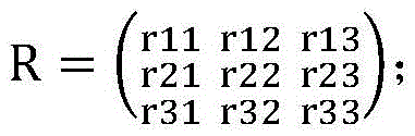
s51, extracting a rotation matrix from the initial calculation result to obtain the rotation matrix:

s55, processing the initial calculation result by preset logic to obtain a translation matrix.
In a more specific technical solution, the step S6 includes:
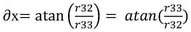
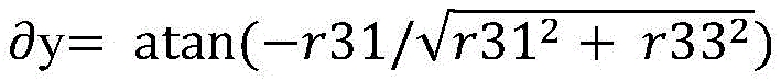
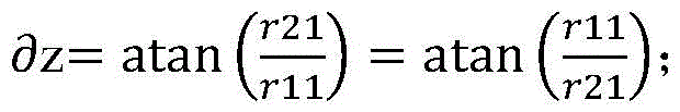
s61, calculating the triaxial rotation Euler angle of a camera coordinate system based on the rotation matrix;
s62, three-axis rotation of the camera coordinates is carried out according to the three-axis rotation Euler angles, so that a world coordinate system parallel coordinate system is obtained;
s63, processing according to the world coordinate system parallel coordinate system to obtain a rotation vector and a translation vector.
In a more specific technical solution, the step S7 includes:
s71, according to the rotation vector, the rotation angle of the XYZ axis in the camera coordinate system is obtained by the following logic:


s72, processing the rotation angle of the XYZ axes, the rotation vector and the translation vector to obtain the coordinates of the camera under the world coordinate system, and taking the coordinates as the known camera coordinates.
In a more specific technical solution, the step S8 includes:
s81, according to the pixel coordinates (u, v) of the target point in the two-dimensional image, the following logic processing is used to obtain the position (Xxm, yxm, zxm) of the target point in the camera coordinate system:
Xxm=(u-u0)*F/fx
Yxm=(v-v0)*F/fy
Zxm=F
wherein F is the focal length of a camera carried by the unmanned aerial vehicle, the units are millimeters, and fx, fy, u0 and v0 are internal reference matrixes of the camera;
s82, carrying out rotation processing on the target point in a camera coordinate system (Xxm, yxm, zxm) around an XYZ axis according to the three-coordinate rotation angle to obtain coordinates (Xm, ym, zm) of the target point in a world coordinate system, and processing to obtain the rays according to the coordinates, wherein the number of the rays is matched with the number of the preset unmanned aerial vehicles;
s83, taking a point at which the two rays intersect or a point at which the two rays are closest to each other as Gaussian coordinates of the target point.
According to the invention, the pose of the camera mounted on the unmanned aerial vehicle is calculated by utilizing a PNP algorithm, further the camera coordinate mounted on the unmanned aerial vehicle is calculated, the rays of the camera and the target point are obtained according to the relation between the camera coordinate system and the image coordinate system, the rays intersect at one point under the real condition, the two straight lines determine one point, the Gaussian coordinate of the target point is obtained, and a means for calculating the Gaussian coordinate of the target point in the image by utilizing the image shot by the unmanned aerial vehicle is provided outside the conventional range finder product.
In a more specific technical scheme, a calculation pixel point gaussian coordinate system based on an unmanned aerial vehicle image comprises:
presetting a camera unmanned aerial vehicle, wherein the camera unmanned aerial vehicle is used for shooting a target area through different angles to obtain at least 2 image data and recording videos;
the characteristic point module is used for extracting at least 2 characteristic points from the image data, processing the characteristic points to obtain pixel points and Gaussian coordinate points of the characteristic points, and connecting the characteristic point module with the preset camera unmanned aerial vehicle;
the camera calibration module is used for obtaining a calibration picture, processing the calibration picture by a preset camera calibration tool to obtain internal parameters, radial distortion parameters and tangential distortion parameters of the camera, and performing calibration operation on the camera according to the internal parameters, the radial distortion parameters and the tangential distortion parameters;
the initial calculation module is used for processing the internal parameter, the radial distortion parameter and the tangential distortion parameter of the camera and the pixel points and the Gaussian coordinate points of the characteristic points by utilizing PNP so as to obtain an initial calculation result, and is connected with the camera calibration module and the characteristic point module;
the feature matrix module is used for processing the initial calculation result to obtain feature matrix data, and is connected with the initial calculation module;
the rotation translation vector module is used for processing the feature matrix data to obtain a triaxial rotation Euler angle of a camera coordinate system, and rotating the camera coordinate according to the triaxial rotation Euler angle to obtain a world coordinate parallel coordinate system so as to obtain a rotation vector and a translation vector, and the rotation translation vector module is connected with the feature matrix module;
the camera coordinate module is used for solving a three-coordinate rotation angle under a camera coordinate system according to the rotation vector and processing the three-coordinate rotation angle, the rotation vector and the translation vector to obtain a camera coordinate;
the target point Gaussian coordinate acquisition module is used for processing and acquiring rays between a target point and a camera by utilizing a preset logic relationship, so as to obtain the target point Gaussian coordinate by processing, and the target point Gaussian coordinate acquisition module is connected with the camera coordinate module, the characteristic point module and the rotary translation vector module.
Compared with the prior art, the invention has the following advantages: according to the unmanned aerial vehicle remote coordinate observation method, the CCD camera mounted on the unmanned aerial vehicle is used for shooting images of the target area from different positions, gaussian coordinates of target points (pixel points) are calculated by utilizing image information, videos of the target points are shot, the unmanned aerial vehicle camera is used for shooting the same area, two images are obtained, the Gaussian coordinates of four points of the same physical position in each image are known, the Gaussian coordinates of any point in the images are obtained by utilizing the pose and space geometry algorithm of the camera, and the unmanned aerial vehicle remote coordinate observation accuracy is improved.
According to the unmanned aerial vehicle shooting method, the hovering height of the unmanned aerial vehicle is set and the shooting angle of the camera is adjusted aiming at the planar terrain area and the complex terrain area with the gradient, so that the position of the target point can be clearly found for shooting, and the shooting effect of the unmanned aerial vehicle is ensured. According to the invention, the unmanned aerial vehicle is utilized to shoot the image, the characteristics of maneuverability and passability of the unmanned aerial vehicle are skillfully utilized to shoot the target point area, and the Gaussian coordinates of the target point in the image are calculated, so that the difficulty of target observation under the condition that part of landform personnel and vehicles cannot reach is effectively solved.
The invention adopts the unmanned aerial vehicle to obtain the two-dimensional image of the position of the target point at a distance of 5 km from the target point and above, and uses the unmanned aerial vehicle to obtain more effective information such as images, videos and the like.
Aiming at the imaging picture deviation caused by errors generated in the production and manufacturing processes of the unmanned aerial vehicle camera, the invention utilizes the MatLab camera calibration tool box to obtain the parameters of internal parameters, radial distortion and tangential distortion of the camera, and the calibration plate is used for calibrating the characteristic points so as to facilitate the calculation of the characteristic points and improve the stability of the unmanned aerial vehicle camera.
According to the invention, the pose of the camera mounted on the unmanned aerial vehicle is calculated by utilizing a PNP algorithm, further the camera coordinate mounted on the unmanned aerial vehicle is calculated, the rays of the camera and the target point are obtained according to the relation between the camera coordinate system and the image coordinate system, the rays intersect at one point under the real condition, the two straight lines determine one point, the Gaussian coordinate of the target point is obtained, and a means for calculating the Gaussian coordinate of the target point in the image by utilizing the image shot by the unmanned aerial vehicle is provided outside the conventional range finder product. The invention solves the technical problems of large remote observation error and difficult observation of special terrain areas in the prior art.
Drawings
Fig. 1 is a flowchart of a method for calculating gaussian coordinates of pixel points based on an unmanned aerial vehicle image according to embodiment 1 of the present invention.
Fig. 2 is a diagram showing camera coordinates in the world coordinate system according to embodiment 1 of the present invention.
Detailed Description
For the purpose of making the objects, technical solutions and advantages of the embodiments of the present invention more apparent, the technical solutions in the embodiments of the present invention will be clearly and completely described in the following in conjunction with the embodiments of the present invention, and it is apparent that the described embodiments are some embodiments of the present invention, but not all embodiments. All other embodiments, which can be made by those skilled in the art based on the embodiments of the invention without making any inventive effort, are intended to be within the scope of the invention.
Example 1
The object of the invention is to take an image of a target area with an unmanned aerial vehicle, calculate Gaussian coordinates of a target point (pixel point) with image information, and take a video of the target point area.
The method comprises the steps of unmanned aerial vehicle shooting and coordinate calculation.
As shown in fig. 1, the implementation flow of the present invention is generally shown, from the previous shooting of a picture, calibration of a camera, and selection of a known point in the shooting of the picture, to the acquisition of a camera coordinate according to a PNP algorithm, the acquisition of a ray from the camera to a target point according to the relationship between an image coordinate system and the camera coordinate system, and then the acquisition of the target point coordinate.
S1, shooting pictures; in the embodiment, the six-rotor unmanned aerial vehicle is selected, the endurance time exceeds one hour, the maximum communication distance is greater than five kilometers, the variable-focus 4K high-definition CCD camera is mounted, the video pixels 1024×720 are collected, and the frame rate is 24FPS.
The unmanned aerial vehicle flies to the target area, two pictures are shot from different angles, and video is recorded. If the target area is formed as a plane, the unmanned aerial vehicle is required to hover at the height of 100-200 meters, if the target area is a slope, the position capable of clearly finding the target point is selected for shooting, and no matter whether the terrain is a plane or a slope, the ground and the ground included angle of the unmanned aerial vehicle camera are ensured to be larger than 45 degrees as much as possible. In addition, when taking pictures from different angles, the focal length of the lens is the same.
S2, calibrating a camera; in this embodiment, errors may occur in the production and manufacturing processes of the unmanned aerial vehicle camera, resulting in deviations between the imaged picture and the actual transaction, which are unavoidable production process deviations. The camera calibration technology is used for calculating camera internal parameters and distortion parameters and correcting images. The camera calibration method adopted by the invention is dynamic camera calibration calibrated by using the calibration plate. The method comprises the specific steps of preparing black-and-white grid pictures of an electronic version, opening the black-and-white grid pictures by using a notebook computer and displaying the black-and-white grid pictures in a full screen mode, then shooting more than 30 black-and-white grid pictures from different angles by using an unmanned aerial vehicle camera, and obtaining camera internal parameters, radial distortion and tangential distortion parameters by using a MatLab camera calibration tool box.
The camera parameters are fx, fy, u0, v0, the radial parameters are k1, k2, k3, and the tangential parameters are p1, p2. For example, the following is the camera parameters of the unmanned aerial vehicle mounted lens used in the project:
{
“fx”:4374.8,
“fy”:4364.9,
“u0”:496.6,
“v0”:496.8,
“k1”:0.4351,
“k2”:-5.3504,
“k3”:24.4242,
“p1”:0.0156,
“p2”:-0.0258
}
s3, taking known points; four common characteristic points are selected from two pictures shot by the unmanned aerial vehicle and serve as known points, so that pixel points and Gaussian coordinate points of the four points are known as known conditions.
S4, calculating camera coordinates; in this embodiment, under the known conditions and camera parameter conditions, the pose of the camera is obtained through PNP (plug-and-play) extrapolation, the invention adopts a solvePnP function provided in OpenCV to calculate, performs rotation matrix extraction and translation matrix on the calculation result, calculates the tri-axis rotation euler angle of the camera coordinate system based on the rotation matrix, and obtains a coordinate system parallel to the world coordinate system after the camera coordinate system is subjected to tri-axis rotation, thereby obtaining a rotation vector and a translation vector. The parametrization of the solvePnP function requires gaussian coordinates of known points, coordinates of known points in the picture, an internal matrix, and distortion parameters.
Wherein the rotation matrix:

rotation angle:


as shown in fig. 2, the rotation angle of the XYZ axis in the camera coordinate system, which is a right-hand coordinate system with the camera as the center and the camera orientation as the Z axis, is obtained from the rotation vector. And obtaining the coordinates of the camera in the world coordinate system according to the rotation angle, the rotation vector and the translation vector of the XYZ axes, so that the camera coordinates are known.
To summarize, up to this point, the known conditions are four known point gaussian coordinates and pixel coordinates, two-shot position coordinates of the camera, and a rotation vector and a translation vector, target point pixel coordinates.
S5, obtaining rays; according to the relation between the image coordinate system and the camera coordinate system, a ray between the target point and the camera can be obtained, so that two rays are obtained, in this embodiment, according to the pixel coordinates (u, v) of the target point in the two-dimensional image, the position (Xxm, yxm, zxm) of the target point in the camera coordinate system is obtained by referring to the following formula:
Xxm=(u-u0)*F/fx
Yxm=(v-v0)*F/fy
Zxm=F
wherein F is the focal length of a camera carried by the unmanned aerial vehicle, the units are millimeters, and fx, fy, u0 and v0 are internal reference matrixes of the camera.
After the above, the coordinates of the target point in the camera coordinate system are obtained, and according to the rotation angle in the step S4, the coordinates (Xm, ym, zm) of the target point in the world coordinate system are obtained after rotating around the XYZ axis.
A straight line (two points form a line) is obtained from the target point position and the camera position, and the target point position is only in one direction of the camera based on the actual situation, so that the target point position can be regarded as a ray. Two rays are obtained by the two unmanned aerial vehicles;
s6, acquiring Gaussian coordinates of the target point; in this embodiment, two rays intersect at a point or the closest point between the two rays is taken, i.e. the gaussian coordinate of the target point.
In summary, the invention uses the CCD camera mounted on the unmanned aerial vehicle to shoot the image of the target area from different positions, calculates the Gaussian coordinate of the target point (pixel point) by using the image information, shoots the video of the target point area, shoots the same area by using the unmanned aerial vehicle camera to obtain two images, knows the Gaussian coordinates of four points of the same physical position in each image, obtains the Gaussian coordinate of any point in the image by using the pose and space geometry algorithm of the camera, and improves the remote coordinate observation accuracy of the unmanned aerial vehicle.
According to the unmanned aerial vehicle shooting method, the hovering height of the unmanned aerial vehicle is set and the shooting angle of the camera is adjusted aiming at the planar terrain area and the complex terrain area with the gradient, so that the position of the target point can be clearly found for shooting, and the shooting effect of the unmanned aerial vehicle is ensured. According to the invention, the unmanned aerial vehicle is utilized to shoot the image, the characteristics of maneuverability and passability of the unmanned aerial vehicle are skillfully utilized to shoot the target point area, and the Gaussian coordinates of the target point in the image are calculated, so that the difficulty of target observation under the condition that part of landform personnel and vehicles cannot reach is effectively solved.
The invention adopts the unmanned aerial vehicle to obtain the two-dimensional image of the position of the target point at a distance of 5 km from the target point and above, and uses the unmanned aerial vehicle to obtain more effective information such as images, videos and the like.
Aiming at the imaging picture deviation caused by errors generated in the production and manufacturing processes of the unmanned aerial vehicle camera, the invention utilizes the MatLab camera calibration tool box to obtain the parameters of internal parameters, radial distortion and tangential distortion of the camera, and the calibration plate is used for calibrating the characteristic points so as to facilitate the calculation of the characteristic points and improve the stability of the unmanned aerial vehicle camera.
According to the invention, the pose of the camera mounted on the unmanned aerial vehicle is calculated by utilizing a PNP algorithm, further the camera coordinate mounted on the unmanned aerial vehicle is calculated, the rays of the camera and the target point are obtained according to the relation between the camera coordinate system and the image coordinate system, the rays intersect at one point under the real condition, the two straight lines determine one point, the Gaussian coordinate of the target point is obtained, and a means for calculating the Gaussian coordinate of the target point in the image by utilizing the image shot by the unmanned aerial vehicle is provided outside the conventional range finder product. The invention solves the technical problems of large remote observation error and difficult observation of special terrain areas in the prior art.
The above embodiments are only for illustrating the technical solution of the present invention, and are not limiting; although the invention has been described in detail with reference to the foregoing embodiments, it will be understood by those of ordinary skill in the art that: the technical scheme described in the foregoing embodiments can be modified or some technical features thereof can be replaced by equivalents; such modifications and substitutions do not depart from the spirit and scope of the technical solutions of the embodiments of the present invention.
Claims (6)
1. A method for calculating gaussian coordinates of pixel points based on unmanned aerial vehicle images, the method comprising:
s1, shooting a target area through different angles by using a preset unmanned aerial vehicle to obtain at least 2 image data, and recording video; the step S1 includes:
s11, acquiring target area data, and accordingly obtaining topographic data and gradient data;
s12, setting the flying height of the preset unmanned aerial vehicle according to the terrain data;
s13, adjusting a camera to a preset shooting angle according to the gradient data;
s2, extracting at least 2 feature points from the image data, and processing to obtain pixel points and Gaussian coordinate points of the feature points, wherein the step S2 comprises the following steps:
s21, selecting 4 characteristic points from 2 pictures shot by the preset unmanned aerial vehicle;
s22, processing the characteristic points to obtain the pixel points and the Gaussian coordinate points;
s3, obtaining a calibration picture, processing the calibration picture by a preset camera calibration tool to obtain internal parameters, radial distortion parameters and tangential distortion parameters of the camera, and accordingly calibrating the camera, wherein the step S3 comprises the following steps:
s31, obtaining black-and-white grid pictures;
s32, opening the black-and-white grid picture with a preset terminal and displaying the black-and-white grid picture in a full screen manner;
s33, shooting the preset number of black and white pictures from different angles by using an unmanned aerial vehicle camera;
s34, processing the black-and-white grid pictures by utilizing a MatLab camera calibration tool box to obtain internal parameters, the radial distortion parameters and the tangential distortion parameters of the camera;
s4, processing internal parameters, radial distortion parameters and tangential distortion parameters of the camera and pixel points and Gaussian coordinate points of the characteristic points by utilizing PNP to obtain an initial calculation result;
s5, processing the initial calculation result to obtain feature matrix data;
s6, processing according to the feature matrix data to obtain a triaxial rotation Euler angle of a camera coordinate system, and rotating the camera coordinate according to triaxial to obtain a world coordinate parallel coordinate system so as to obtain a rotation vector and a translation vector;
s7, obtaining a three-coordinate rotation angle under a camera coordinate system according to the rotation vector, and processing the three-coordinate rotation angle, the rotation vector and the translation vector to obtain a camera coordinate;
s8, acquiring rays between the target point and the camera by utilizing a preset logic relation process, and processing to obtain Gaussian coordinates of the target point, wherein the step S8 comprises the following steps:
s81, according to the pixel coordinates (u, v) of the target point in the two-dimensional image, the following logic processing is used to obtain the position (Xxm, yxm, zxm) of the target point in the camera coordinate system:
Xxm=(u-u0)*F/fx
Yxm=(v-v0)*F/fy
Zxm=F
f is the focal length of a camera carried by the unmanned aerial vehicle, the units are millimeter, and fx, fy, u0 and v0 are internal reference matrixes of the camera;
s82, carrying out rotation processing on the target point in a camera coordinate system (Xxm, yxm, zxm) around an XYZ axis according to the three-coordinate rotation angle to obtain coordinates (Xm, ym, zm) of the target point in a world coordinate system, and processing to obtain the rays according to the coordinates, wherein the number of the rays is matched with the number of the preset unmanned aerial vehicles;
s83, taking a point at which the rays intersect or a point at which two rays are closest to each other as Gaussian coordinates of the target point.
2. The method of claim 1, wherein in the step S4, a solvePnP function in OpenCV is used to calculate the internal parameters, radial distortion parameters, tangential distortion parameters, and pixel points and gaussian coordinate points of the feature points of the camera, so as to obtain the initial calculation result.
3. The method of calculating gaussian coordinates of a pixel point based on an image of an unmanned aerial vehicle according to claim 1, wherein said step S5 comprises:
s51, extracting a rotation matrix from the initial calculation result to obtain the rotation matrix:
s55, processing the initial calculation result by preset logic to obtain a translation matrix.
4. The method of calculating gaussian coordinates of a pixel point based on an image of an unmanned aerial vehicle according to claim 1, wherein said step S6 comprises:
s61, calculating the triaxial rotation Euler angle of a camera coordinate system based on a rotation matrix;
s62, three-axis rotation of the camera coordinates is carried out according to the three-axis rotation Euler angles, so that a world coordinate parallel coordinate system is obtained;
s63, processing according to a world coordinate system and a parallel coordinate system to obtain a rotation vector and a translation vector.
5. The method of calculating gaussian coordinates of a pixel point based on an image of an unmanned aerial vehicle according to claim 1, wherein said step S7 comprises:
s71, according to the rotation vector, the rotation angle of the XYZ axis in the camera coordinate system is obtained by the following logic:
s72, processing the rotation angle of the XYZ axes, the rotation vector and the translation vector to obtain the coordinates of the camera under the world coordinate system, and taking the coordinates as the known camera coordinates.
6. A gaussian coordinate system for calculating pixel points based on an image of an unmanned aerial vehicle, the system comprising:
the method comprises the steps of presetting a camera unmanned aerial vehicle, wherein the camera unmanned aerial vehicle is used for shooting target areas through different angles to obtain at least 2 parts of image data, recording videos, obtaining target area data, obtaining terrain data and gradient data according to the target area data, setting the flight height of the preset unmanned aerial vehicle according to the terrain data, and adjusting a camera to a preset shooting angle according to the gradient data;
the characteristic point module is used for extracting at least 2 characteristic points from the image data, processing pixel points and Gaussian coordinate points of the characteristic points according to the characteristic points, and connecting the characteristic point module with the preset camera unmanned aerial vehicle, wherein 4 characteristic points are selected from 2 pictures shot by the preset unmanned aerial vehicle; processing the characteristic points to obtain the pixel points and the Gaussian coordinate points;
the camera calibration module is used for obtaining a calibration picture, processing the calibration picture by a preset camera calibration tool to obtain internal parameters, radial distortion parameters and tangential distortion parameters of the camera, and accordingly performing calibration operation on the camera, wherein black-and-white grid pictures are obtained; opening the black-and-white grid picture with a preset terminal and displaying the black-and-white grid picture in a full screen manner; shooting the preset number of black and white pictures from different angles by using an unmanned aerial vehicle camera; processing the black-and-white grid pictures by using a MatLab camera calibration tool box to obtain internal parameters, the radial distortion parameters and the tangential distortion parameters of the camera;
the initial calculation module is used for processing the internal parameter, the radial distortion parameter and the tangential distortion parameter of the camera and the pixel points and the Gaussian coordinate points of the characteristic points by utilizing PNP so as to obtain an initial calculation result, and is connected with the camera calibration module and the characteristic point module;
the feature matrix module is used for processing the initial calculation result to obtain feature matrix data, and is connected with the initial calculation module;
the rotation translation vector module is used for processing the feature matrix data to obtain a triaxial rotation Euler angle of a camera coordinate system, and rotating the camera coordinate according to the triaxial rotation Euler angle to obtain a world coordinate parallel coordinate system so as to obtain a rotation vector and a translation vector, and the rotation translation vector module is connected with the feature matrix module;
the camera coordinate module is used for solving a three-coordinate rotation angle under a camera coordinate system according to the rotation vector and processing the three-coordinate rotation angle, the rotation vector and the translation vector to obtain a camera coordinate;
the target point Gaussian coordinate acquisition module is used for processing and acquiring rays between a target point and a camera by utilizing a preset logic relation to obtain target point Gaussian coordinates, and is connected with the camera coordinate module, the characteristic point module and the rotation translation vector module, wherein the target point is positioned in a camera coordinate system (Xxm, yxm, zxm) by utilizing the following logic processing according to pixel coordinates (u, v) of the target point in a two-dimensional image:
Xxm=(u-u0)*F/fx
Yxm=(v-v0)*F/fy
Zxm=F
f is the focal length of a camera carried by the unmanned aerial vehicle, the units are millimeter, and fx, fy, u0 and v0 are internal reference matrixes of the camera;
performing rotation processing on the target point in a camera coordinate system according to the three-coordinate rotation angle around an XYZ axis (Xxm, yxm, zxm) so as to obtain coordinates (Xm, ym, zm) of the target point in a world coordinate system, and processing according to the coordinates to obtain the rays, wherein the number of the rays is matched with the number of the preset unmanned aerial vehicles;
and taking a point at which the rays intersect or a point at which two rays are closest to each other as Gaussian coordinates of the target point.
Priority Applications (1)
| Application Number | Priority Date | Filing Date | Title |
|---|---|---|---|
| CN202210688663.1A CN114926552B (en) | 2022-06-17 | 2022-06-17 | Method and system for calculating Gaussian coordinates of pixel points based on unmanned aerial vehicle image |
Applications Claiming Priority (1)
| Application Number | Priority Date | Filing Date | Title |
|---|---|---|---|
| CN202210688663.1A CN114926552B (en) | 2022-06-17 | 2022-06-17 | Method and system for calculating Gaussian coordinates of pixel points based on unmanned aerial vehicle image |
Publications (2)
| Publication Number | Publication Date |
|---|---|
| CN114926552A CN114926552A (en) | 2022-08-19 |
| CN114926552B true CN114926552B (en) | 2023-06-27 |
Family
ID=82814487
Family Applications (1)
| Application Number | Title | Priority Date | Filing Date |
|---|---|---|---|
| CN202210688663.1A Active CN114926552B (en) | 2022-06-17 | 2022-06-17 | Method and system for calculating Gaussian coordinates of pixel points based on unmanned aerial vehicle image |
Country Status (1)
| Country | Link |
|---|---|
| CN (1) | CN114926552B (en) |
Families Citing this family (4)
| Publication number | Priority date | Publication date | Assignee | Title |
|---|---|---|---|---|
| CN115752382B (en) * | 2022-11-18 | 2025-12-02 | 深圳赛尔智控科技有限公司 | A method, apparatus, device, and storage medium for correcting aerial photograph offset data. |
| CN116309875B (en) * | 2023-03-22 | 2025-12-05 | 北京航空航天大学 | A method for separating intrinsic and extrinsic parameters of a long-range imaging camera based on a precision three-axis rotary table. |
| CN117237512B (en) * | 2023-11-10 | 2024-03-12 | 深圳市易图资讯股份有限公司 | Three-dimensional scene mapping method and system for video image |
| CN118521646B (en) * | 2024-07-25 | 2024-11-19 | 中国铁塔股份有限公司江西省分公司 | Image processing-based multi-machine type unmanned aerial vehicle power receiving frame alignment method and system |
Citations (4)
| Publication number | Priority date | Publication date | Assignee | Title |
|---|---|---|---|---|
| CN104835115A (en) * | 2015-05-07 | 2015-08-12 | 中国科学院长春光学精密机械与物理研究所 | Imaging method for aerial camera, and system thereof |
| CN106227237A (en) * | 2016-09-29 | 2016-12-14 | 广州极飞科技有限公司 | The distribution method of the aerial mission of unmanned plane and device |
| CN106356757A (en) * | 2016-08-11 | 2017-01-25 | 河海大学常州校区 | Method for inspecting electric power lines by aid of unmanned aerial vehicle on basis of human vision characteristics |
| CN106373159A (en) * | 2016-08-30 | 2017-02-01 | 中国科学院长春光学精密机械与物理研究所 | Simplified unmanned aerial vehicle multi-target location method |
Family Cites Families (6)
| Publication number | Priority date | Publication date | Assignee | Title |
|---|---|---|---|---|
| CN104333675B (en) * | 2014-10-20 | 2017-09-05 | 长春理工大学 | A Method of Panoramic Electronic Image Stabilization Based on Spherical Projection |
| CN105004354B (en) * | 2015-06-19 | 2017-12-05 | 北京航空航天大学 | Unmanned plane visible ray and infrared image object localization method under large slanting view angle machine |
| CN108648237B (en) * | 2018-03-16 | 2022-05-03 | 中国科学院信息工程研究所 | A Vision-Based Spatial Localization Method |
| CN109685913B (en) * | 2018-12-21 | 2022-12-02 | 西安电子科技大学 | Augmented Reality Realization Method Based on Computer Vision Positioning |
| CN113191296A (en) * | 2021-05-13 | 2021-07-30 | 中国人民解放军陆军炮兵防空兵学院 | Method for detecting five parameters of target in any orientation based on YOLOV5 |
| CN114299156A (en) * | 2021-12-11 | 2022-04-08 | 合肥辰视机器人科技有限公司 | Method for calibrating and unifying coordinates of multiple cameras in non-overlapping area |
-
2022
- 2022-06-17 CN CN202210688663.1A patent/CN114926552B/en active Active
Patent Citations (4)
| Publication number | Priority date | Publication date | Assignee | Title |
|---|---|---|---|---|
| CN104835115A (en) * | 2015-05-07 | 2015-08-12 | 中国科学院长春光学精密机械与物理研究所 | Imaging method for aerial camera, and system thereof |
| CN106356757A (en) * | 2016-08-11 | 2017-01-25 | 河海大学常州校区 | Method for inspecting electric power lines by aid of unmanned aerial vehicle on basis of human vision characteristics |
| CN106373159A (en) * | 2016-08-30 | 2017-02-01 | 中国科学院长春光学精密机械与物理研究所 | Simplified unmanned aerial vehicle multi-target location method |
| CN106227237A (en) * | 2016-09-29 | 2016-12-14 | 广州极飞科技有限公司 | The distribution method of the aerial mission of unmanned plane and device |
Also Published As
| Publication number | Publication date |
|---|---|
| CN114926552A (en) | 2022-08-19 |
Similar Documents
| Publication | Publication Date | Title |
|---|---|---|
| CN114926552B (en) | Method and system for calculating Gaussian coordinates of pixel points based on unmanned aerial vehicle image | |
| CN110648283B (en) | Image splicing method and device, electronic equipment and computer readable storage medium | |
| CN109146980B (en) | Monocular vision based optimized depth extraction and passive distance measurement method | |
| CN109269430B (en) | Passive measurement method of diameter at breast height of multiple standing trees based on depth extraction model | |
| CN115187798A (en) | Multi-unmanned aerial vehicle high-precision matching positioning method | |
| CN113205603B (en) | A 3D point cloud stitching and reconstruction method based on a rotating stage | |
| CN108665499B (en) | Near distance airplane pose measuring method based on parallax method | |
| EP2847741B1 (en) | Camera scene fitting of real world scenes for camera pose determination | |
| CN110930508B (en) | Two-dimensional photoelectric video and three-dimensional scene fusion method | |
| CN110969663A (en) | Static calibration method for external parameters of camera | |
| CN110595476A (en) | Unmanned aerial vehicle landing navigation method and device based on GPS and image visual fusion | |
| CN104268935A (en) | Feature-based airborne laser point cloud and image data fusion system and method | |
| CN102779347A (en) | Method and device for tracking and locating target for aircraft | |
| CN110517284B (en) | A Target Tracking Method Based on LiDAR and PTZ Camera | |
| CN116718165A (en) | A joint imaging system and image enhancement fusion method based on UAV platform | |
| CN114743021A (en) | Fusion method and system of power transmission line image and point cloud data | |
| CN113313659A (en) | High-precision image splicing method under multi-machine cooperative constraint | |
| CN106871900A (en) | Image matching positioning method in ship magnetic field dynamic detection | |
| CN110083177A (en) | A kind of quadrotor and control method of view-based access control model landing | |
| US20250261578A1 (en) | Precision agriculture using pose georeferenced analtyics | |
| CN115690612B (en) | Unmanned aerial vehicle photoelectric image target searching quantization indication method, equipment and medium | |
| Abanay et al. | A calibration method of 2D LIDAR-Visual sensors embedded on an agricultural robot | |
| Xinmei et al. | Passive measurement method of tree height and crown diameter using a smartphone | |
| CN108007437B (en) | A method for measuring farmland boundaries and internal obstacles based on multi-rotor aircraft | |
| CN110160503B (en) | A UAV Landscape Matching and Localization Method Considering Elevation |
Legal Events
| Date | Code | Title | Description |
|---|---|---|---|
| PB01 | Publication | ||
| PB01 | Publication | ||
| SE01 | Entry into force of request for substantive examination | ||
| SE01 | Entry into force of request for substantive examination | ||
| GR01 | Patent grant | ||
| GR01 | Patent grant |