CN114914801A - High-low voltage switch cabinet safe in operation - Google Patents
High-low voltage switch cabinet safe in operation Download PDFInfo
- Publication number
- CN114914801A CN114914801A CN202210321326.9A CN202210321326A CN114914801A CN 114914801 A CN114914801 A CN 114914801A CN 202210321326 A CN202210321326 A CN 202210321326A CN 114914801 A CN114914801 A CN 114914801A
- Authority
- CN
- China
- Prior art keywords
- cabinet
- door
- rod
- cabinet body
- rotating shaft
- Prior art date
- Legal status (The legal status is an assumption and is not a legal conclusion. Google has not performed a legal analysis and makes no representation as to the accuracy of the status listed.)
- Granted
Links
- 238000009434 installation Methods 0.000 claims abstract description 18
- 230000007246 mechanism Effects 0.000 claims description 44
- 230000005540 biological transmission Effects 0.000 claims description 24
- 229910000831 Steel Inorganic materials 0.000 claims description 18
- 239000010959 steel Substances 0.000 claims description 18
- 230000001681 protective effect Effects 0.000 claims description 8
- 230000000007 visual effect Effects 0.000 claims description 6
- 230000008878 coupling Effects 0.000 claims description 3
- 238000010168 coupling process Methods 0.000 claims description 3
- 238000005859 coupling reaction Methods 0.000 claims description 3
- 230000001105 regulatory effect Effects 0.000 claims description 2
- 238000000926 separation method Methods 0.000 claims description 2
- 230000006978 adaptation Effects 0.000 claims 1
- 238000012423 maintenance Methods 0.000 abstract description 24
- 238000000034 method Methods 0.000 description 6
- 238000010586 diagram Methods 0.000 description 3
- 230000008569 process Effects 0.000 description 3
- 230000007547 defect Effects 0.000 description 2
- 238000003780 insertion Methods 0.000 description 2
- 230000037431 insertion Effects 0.000 description 2
- 230000004048 modification Effects 0.000 description 2
- 238000012986 modification Methods 0.000 description 2
- 230000009471 action Effects 0.000 description 1
- 230000009286 beneficial effect Effects 0.000 description 1
- 238000004891 communication Methods 0.000 description 1
- 238000010276 construction Methods 0.000 description 1
- 238000005520 cutting process Methods 0.000 description 1
- 238000001514 detection method Methods 0.000 description 1
- 230000000694 effects Effects 0.000 description 1
- 238000005516 engineering process Methods 0.000 description 1
- 230000006872 improvement Effects 0.000 description 1
- 238000004519 manufacturing process Methods 0.000 description 1
- 238000003825 pressing Methods 0.000 description 1
Images


Classifications
-
- H—ELECTRICITY
- H02—GENERATION; CONVERSION OR DISTRIBUTION OF ELECTRIC POWER
- H02B—BOARDS, SUBSTATIONS OR SWITCHING ARRANGEMENTS FOR THE SUPPLY OR DISTRIBUTION OF ELECTRIC POWER
- H02B1/00—Frameworks, boards, panels, desks, casings; Details of substations or switching arrangements
- H02B1/26—Casings; Parts thereof or accessories therefor
- H02B1/30—Cabinet-type casings; Parts thereof or accessories therefor
-
- G—PHYSICS
- G01—MEASURING; TESTING
- G01R—MEASURING ELECTRIC VARIABLES; MEASURING MAGNETIC VARIABLES
- G01R31/00—Arrangements for testing electric properties; Arrangements for locating electric faults; Arrangements for electrical testing characterised by what is being tested not provided for elsewhere
- G01R31/50—Testing of electric apparatus, lines, cables or components for short-circuits, continuity, leakage current or incorrect line connections
- G01R31/52—Testing for short-circuits, leakage current or ground faults
-
- H—ELECTRICITY
- H02—GENERATION; CONVERSION OR DISTRIBUTION OF ELECTRIC POWER
- H02B—BOARDS, SUBSTATIONS OR SWITCHING ARRANGEMENTS FOR THE SUPPLY OR DISTRIBUTION OF ELECTRIC POWER
- H02B1/00—Frameworks, boards, panels, desks, casings; Details of substations or switching arrangements
- H02B1/26—Casings; Parts thereof or accessories therefor
- H02B1/30—Cabinet-type casings; Parts thereof or accessories therefor
- H02B1/38—Hinged covers or doors
-
- H—ELECTRICITY
- H02—GENERATION; CONVERSION OR DISTRIBUTION OF ELECTRIC POWER
- H02H—EMERGENCY PROTECTIVE CIRCUIT ARRANGEMENTS
- H02H5/00—Emergency protective circuit arrangements for automatic disconnection directly responsive to an undesired change from normal non-electric working conditions with or without subsequent reconnection
- H02H5/12—Emergency protective circuit arrangements for automatic disconnection directly responsive to an undesired change from normal non-electric working conditions with or without subsequent reconnection responsive to undesired approach to, or touching of, live parts by living beings
Abstract
The invention discloses a high-low voltage switch cabinet with safe operation, which relates to the technical field of high-low voltage switch cabinets and comprises a cabinet body, wherein an electric leakage alarm is arranged on the cabinet body, an alarm and a warning lamp are arranged at the top of the cabinet body, the alarm and the warning lamp are both coupled and connected with the electric leakage alarm, an opening is arranged on the front surface of the cabinet body, and a cabinet door is hinged at the position of the opening, and the high-low voltage switch cabinet is characterized in that: the internal side wall of cabinet that the cabinet body open position department was located is provided with the chimb, and the chimb is close to opening one side and forms cabinet door installation cavity, the articulated setting of cabinet door is inside cabinet door installation cavity when cabinet door installation cavity closes, the inside wall of cabinet door hugs closely in the chimb. After maintenance is finished, the visible inner door can be separated from the outer door by rotating the handle, the front side of the cabinet body is sealed by the visible inner door, meanwhile, a circuit in the cabinet body is connected, maintenance conditions can be checked, and meanwhile, the cabinet body is sealed by the visible inner door, so that the operation safety is ensured.
Description
Technical Field
The invention relates to the technical field of high-low voltage switch cabinets, in particular to a high-low voltage switch cabinet safe to operate.
Background
The high-low voltage switch cabinet is equipment for connecting high-voltage or low-voltage cables.
Present high-low voltage switch cabinet is only opened and close through single switch when operating the cabinet door, this just leads to the non-staff to open it easily, thereby lead to the production of electric shock accident, danger is higher, protect high-low voltage switch cabinet for better simultaneously, can be at the internal leakage alarm ware that sets up of cabinet, with this internal electric leakage condition of detection cabinet, at present when the internal leakage worker of cabinet maintains, need cut off the power supply to the electric current that inserts in the high-low voltage switch cabinet earlier, then opening cabinet door maintenance, present operation defect lies in can not cutting off the power supply to high-low voltage switch cabinet when the cabinet door is opened, preorder operation consumes time longer when making to maintain the cabinet internal, can not maintain for the very first time.
Disclosure of Invention
The invention aims to provide a high-low voltage switch cabinet safe to operate, and aims to solve the problems that in the background technology, when electrician workers are leaked in a cabinet body to maintain, the current connected into the high-low voltage switch cabinet needs to be cut off firstly, then the cabinet door is opened for maintenance, and the current operation defect is that the power cannot be cut off in the high-low voltage switch cabinet when the cabinet door is opened, so that the preorder operation is long in time when the cabinet body is maintained, and the cabinet body cannot be maintained for the first time.
In order to achieve the purpose, the invention adopts the following technical scheme:
the invention provides a high-low voltage switch cabinet safe in operation, which comprises a cabinet body, wherein an electric leakage alarm is installed on the cabinet body, an alarm and a warning lamp are installed at the top of the cabinet body, the alarm and the warning lamp are both coupled with the electric leakage alarm, an opening is formed in the front of the cabinet body, and a cabinet door is hinged to the opening position, and the high-low voltage switch cabinet safe in operation is characterized in that: the cabinet body is characterized in that a convex edge is arranged on the inner side wall of the cabinet body at the position of the opening of the cabinet body, a cabinet door installation cavity is formed on one side, close to the opening, of the convex edge, the cabinet door is hinged to the interior of the cabinet door installation cavity, and when the cabinet door installation cavity is closed, the inner side wall of the cabinet door is tightly attached to the convex edge;
the cabinet door comprises:
the rotating shaft is rotatably arranged on one side of the cabinet door mounting cavity along the height direction of the cabinet body, and two ends of the rotating shaft penetrate through the upper side wall and the lower side wall of the cabinet body and extend to the upper part and the lower part of the cabinet body to form a power-off end and a grounding end respectively;
the outer door is rotatably arranged on the rotating shaft; the outer door can circumferentially rotate around the rotating shaft, an embedding cavity is formed in the inner side face of the outer door, a visible inner door is embedded in the embedding cavity, one side of the visible inner door is fixedly connected with the rotating shaft, an adjusting column is rotatably arranged on the outer side wall of the outer door, one end of the adjusting column extends into the embedding cavity, and a handle is fixed to the other end of the adjusting column;
the separation mechanism comprises a rotating rod, push rods and fixing strips, wherein the rotating rod is parallel to the rotating shaft and is rotatably arranged on one side, close to the rotating shaft, of the embedded cavity, the push rods are symmetrically fixed at two ends of the rotating rod, and the fixing strips are fixed on one side, close to the outer door, of the visible inner door corresponding to the push rods; the separating mechanism comprises a rotating rod, a fixed rod, a separating mechanism and a separating mechanism, wherein the rotating rod is arranged on the rotating rod, the separating mechanism is arranged on the rotating rod, the rotating rod is arranged on the side, away from the rotating rod, of the fixed rod, the separating mechanism is arranged on the side, away from the rotating rod, of the fixed rod, the fixed rod is clamped inside the through groove, and the separating mechanism further comprises a first transmission assembly in transmission connection with the regulating rod; the first transmission assembly is used for driving the rotating rod to rotate forwards and reversely;
the outer door locking mechanism comprises sliding strips which are symmetrically and longitudinally arranged at the upper end and the lower end of the embedding cavity in a sliding manner, an inserted rod which is longitudinally fixed at one side of the sliding strips, which is close to the rotating shaft, and return springs which are arranged at the back sides of the two sliding strips; arc-shaped grooves are formed in the upper inner side wall and the lower inner side wall of the cabinet door mounting cavity on the outer side of the rotating shaft, sawteeth are arranged at the bottoms of the arc-shaped grooves, one end, away from the sliding strip, of the inserted rod penetrates through the outer door and extends to the inner part corresponding to the arc-shaped grooves, the outer door locking mechanism further comprises a second transmission assembly in transmission connection with the adjusting column, and the second transmission assembly is used for driving the sliding strip to longitudinally slide;
the high-low voltage switch cabinet safe in operation further comprises a power-off mechanism for powering off the internal part of the cabinet and a grounding mechanism for grounding a circuit in the internal part of the cabinet, when the rotating shaft rotates to close or close the cabinet door, the power-off end can break or break a circuit in the internal part of the cabinet, and the grounding end can break or break a circuit in the internal part of the cabinet and a ground wire.
Furthermore, the power-off mechanism comprises a first protective shell, a first press switch arranged on the side wall of the first protective shell and a first trigger rod fixed at the power-off end of the rotating shaft; first press switch and current input end and output end coupling are connected when the inside wall of visual inner door hugs closely the chimb, the first trigger bar of outage end is contradicted in first press switch and is used for putting through cabinet body internal circuit.
Furthermore, the grounding mechanism comprises a second protective shell, a second press switch arranged on the side wall of the second protective shell and a second trigger rod fixed at the grounding end of the rotating shaft; the second press switch is coupled with the internal circuit of the cabinet and the ground wire, and when the inner side wall of the visual inner door is not attached with the convex edge, the second trigger rod of the ground end abuts against the second press switch to be used for connecting the internal circuit of the cabinet and the ground wire.
Further, the first transmission assembly comprises a gear roller assembled in the middle of the rotating rod, a rack plate which slides along the width direction of the cabinet door and is meshed with the gear roller, and a U-shaped frame which is fixedly connected with the rack plate and can slide along the width direction of the cabinet door; the adjusting column is vertically fixed at the edge position far away from one end of the handle, connecting rods are fixedly connected to the upper parts of the inner sides of the U-shaped frames on the two sides of the adjusting column, and the bottoms of the connecting rods are flush with the horizontal plane where the circle center of the adjusting column is located.
Furthermore, a base point, a first steel wire rope fixing point and a second steel wire rope fixing point are respectively arranged on the circumference of the adjusting column; the basic point is located the plane that passes the post and adjust the post axis, the basic point use the axis of adjusting the post as the rotation axis along clockwise rotation 90 degrees after with first wire rope fixed point coincidence, the basic point use adjust the post axis as the rotation axis anticlockwise rotation 90 degrees after with second wire rope fixed point coincidence, the second drive assembly includes first wire rope and second wire rope, first wire rope's one end and first wire rope fixed point fixed connection, first wire rope's the other end and the sliding strip fixed connection who is located the lower part, the one end of second wire rope and the fixed connection of second wire rope fixed point, the other end of second wire rope is located the sliding strip fixed connection on upper portion.
Further, the handle and pull post are located in a plane passing through the axis of the adjustment post.
Further, the middle part that rotation axis one side was kept away from to the outer door is seted up flutedly, the cabinet door installation cavity is kept away from rotation axis one side and is provided with locking mechanical system, locking mechanical system includes the locked groove, the inside slip of locked groove is provided with the slider, the slider with be provided with the pressure spring between the locked groove, one side that the chimb was kept away from to one side that the pressure spring was kept away from to the slider is provided with the inclined plane, one side that the slider is close to the pressure spring is provided with the through-hole, the inside wall of through-hole is provided with the helicla flute, the cabinet body corresponds locked groove position department is provided with rotatory handle, one side fixedly connected with rotary rod of rotatory handle, the rotary rod runs through the cabinet body and extends to the inside fixedly connected with dead lever of through-hole, the dead lever is inserted and is established inside the helicla flute.
Furthermore, the upper end and the lower end of one side, close to the rotating shaft, of the outer door are provided with lantern rings, the lantern rings are sleeved on the rotating shaft, and the outer door is matched with the cabinet door mounting cavity.
Compared with the prior art, the above one or more technical schemes have the following beneficial effects:
1. the power-off mechanism arranged in the invention can power off the cabinet body when the cabinet door is opened, and the power off of the cabinet body is not needed before maintenance, so that the maintenance speed of the cabinet body is accelerated, and the economic and property losses caused by high temperature fire disasters generated by electric leakage in the cabinet body are avoided.
2. After maintenance is finished, the visible inner door can be separated from the outer door by rotating the handle, the front side of the cabinet body is sealed by the visible inner door, meanwhile, a circuit in the cabinet body is connected, maintenance conditions can be checked, and meanwhile, the cabinet body is sealed by the visible inner door, so that the operation safety is ensured.
3. According to the outer door locking mechanism provided by the invention, after the handle is loosened, the inserted rod can be inserted into the sawteeth to lock the outer door, so that the maintenance of maintenance personnel is facilitated, and the influence on maintenance caused by the shaking of the cabinet door during maintenance is avoided.
4. The locking mechanism and the outer door locking mechanism have the effect of double locking, and the problem that a non-working person is easy to open the cabinet door due to the fact that a single switch is arranged on the cabinet door, and electric shock accidents are caused is avoided.
Drawings
The accompanying drawings, which are incorporated in and constitute a part of this specification, are included to provide a further understanding of the invention, and are incorporated in and constitute a part of this specification, illustrate exemplary embodiments of the invention and together with the description serve to explain the invention and not to limit the invention.
In the drawings:
FIG. 1 is a schematic structural view of the cabinet body of the present invention when the cabinet door is closed;
FIG. 2 is a schematic view of a first state of the present invention with the outer door separated from the inner door;
FIG. 3 is a schematic view of a second state of the present invention with the outer door separated from the inner door;
FIG. 4 is a schematic structural view of the cabinet door of the cabinet body of the present invention when opened and closed;
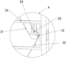
FIG. 5 is a schematic view of a portion of the structure of FIG. 2 at A;
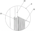
FIG. 6 is a schematic view of a portion of the structure of FIG. 3 at B;
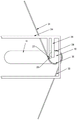
FIG. 7 is a schematic view of a portion of the structure of FIG. 3 at C;
FIG. 8 is a schematic view of a portion of the structure of FIG. 3 at D;
FIG. 9 is a schematic structural diagram of the power-off mechanism of the present invention;
FIG. 10 is a schematic structural diagram of a grounding mechanism according to the present invention;
FIG. 11 is a schematic view of a structure of a circular arc groove according to the present invention;
FIG. 12 is a schematic view of the locking mechanism of the present invention;
FIG. 13 is a schematic view of the initial state structure of the handle of the present invention;
FIG. 14 is a structural view of the handle in a first state according to the present invention;
fig. 15 is a structural diagram of the handle in the second state according to the present invention.
Detailed Description
In order to make the technical solutions better understood by those skilled in the art, the technical solutions in the embodiments of the present application will be clearly and completely described below with reference to the drawings in the embodiments of the present application, and it is obvious that the described embodiments are only partial embodiments of the present application, but not all embodiments. All other embodiments obtained by a person of ordinary skill in the art based on the embodiments in the present application without making any creative effort shall fall within the protection scope of the present application.
It should be noted that the terms "first," "second," and the like in the description and claims of this application and in the drawings described above are used for distinguishing between similar elements and not necessarily for describing a particular sequential or chronological order. It should be understood that the data so used may be interchanged under appropriate circumstances such that embodiments of the application described herein may be used. Moreover, the terms "comprises," "comprising," and "having," and any variations thereof, are intended to cover a non-exclusive inclusion, such that a process, method, system, article, or apparatus that comprises a list of steps or elements is not necessarily limited to those steps or elements expressly listed, but may include other steps or elements not expressly listed or inherent to such process, method, article, or apparatus.
In this application, the terms "upper", "lower", "left", "right", "front", "rear", "top", "bottom", "inner", "outer", "middle", "vertical", "horizontal", "lateral", "longitudinal", and the like indicate orientations or positional relationships based on the orientations or positional relationships shown in the drawings. These terms are used primarily to better describe the present application and its embodiments, and are not used to limit the indicated devices, elements or components to a particular orientation or to be constructed and operated in a particular orientation.
Moreover, some of the above terms may be used to indicate other meanings besides the orientation or positional relationship, for example, the term "on" may also be used to indicate some kind of attachment or connection relationship in some cases. The specific meaning of these terms in this application will be understood by those of ordinary skill in the art as appropriate.
Furthermore, the terms "mounted," "disposed," "provided," "connected," and "sleeved" are to be construed broadly. For example, it may be a fixed connection, a removable connection, or a unitary construction; can be a mechanical connection, or an electrical connection; may be directly connected, or indirectly connected through intervening media, or may be in internal communication between two devices, elements or components. The specific meaning of the above terms in the present application can be understood by those of ordinary skill in the art as the case may be.
As shown in fig. 1-10, the high-low voltage switch cabinet with safe operation comprises a cabinet body 1, wherein an electric leakage alarm is installed on the cabinet body 1, an alarm and a warning lamp are installed at the top of the cabinet body 1, and the alarm and the warning lamp are both coupled with the electric leakage alarm. In this embodiment, when the electric leakage alarm detects the internal electric leakage of cabinet 1, can take place the warning through alarm and warning light, remind operating personnel.
Specifically, please refer to fig. 1 and fig. 4, the cabinet body 1 has an opening in the front, a cabinet door is hinged at the opening position, a convex edge 2 is disposed on the inner side wall of the cabinet body 1 at the opening position of the cabinet body 1, the convex edge 2 is close to one side of the opening to form a cabinet door installation chamber 3, the cabinet door is hinged inside the cabinet door installation chamber 3, and when the cabinet door installation chamber 3 is closed, the inner side wall of the cabinet door is tightly attached to the convex edge 2. When the cabinet door is closed, the cabinet door is accommodated in the cabinet door mounting cavity 3, so that the cabinet body 1 is straight and attractive in front.
The high-low voltage switch cabinet safe in operation further comprises a power-off mechanism for powering off the inside of the cabinet body 1 and a grounding mechanism for grounding a circuit inside the cabinet body 1. The overall safety performance of the cabinet body 1 is improved.
Referring specifically to fig. 2, 3, 9 and 10, the cabinet door includes: the rotating shaft 4 is rotatably arranged on one side of the cabinet door installation cavity 3 along the height direction of the cabinet body 1, and two ends of the rotating shaft 4 penetrate through the upper side wall and the lower side wall of the cabinet body 1 and extend to the upper part and the lower part of the cabinet body 1 to form a power-off end 5 and a grounding end 6 respectively;
referring to fig. 2, 3 and 5, the outer door 7 is rotatably disposed on the rotating shaft 4; the outer door 7 can circumferentially rotate around the rotating shaft 4, the inner side face of the outer door 7 is provided with an embedding cavity 8, a visible inner door 9 is embedded inside the embedding cavity 8, one side of the visible inner door 9 is fixedly connected with the rotating shaft 4, the outer side wall of the outer door 7 is rotatably provided with an adjusting column 10, one end of the adjusting column 10 extends into the embedding cavity 8, and the other end of the adjusting column 10 is fixedly provided with a handle 11;
referring to fig. 2, 3 and 7, the separating mechanism includes a rotating rod 12 parallel to the rotating shaft 4 and rotatably disposed on one side of the embedding cavity 8 close to the rotating shaft 4, push rods 13 symmetrically fixed at two ends of the rotating rod 12, and a fixing strip 14 fixed on one side of the visible inner door 9 close to the outer door 7 corresponding to the push rods 13; the fixing strip 14 is longitudinally provided with a through groove 15 along the length direction, one side of the push rod 13, which is far away from the rotating rod 12, is longitudinally fixed with a fixing column 16, the fixing column 16 is clamped inside the through groove 15, the separating mechanism further comprises a first transmission assembly in transmission connection with the adjusting column 10, and the first transmission assembly is used for driving the rotating rod 12 to rotate forwards and reversely;
referring to fig. 2, 3, 6 and 11, the locking mechanism of the outer door 7 includes sliding bars 17 symmetrically and longitudinally slidably disposed at the upper and lower ends of the embedding cavity 8, inserting rods 18 longitudinally fixed at one side of the sliding bars 17 close to the rotating shaft 4, and return springs 19 disposed at the back sides of the two sliding bars 17; arc-shaped grooves 20 are formed in the upper inner side wall and the lower inner side wall of the cabinet door mounting cavity 3 on the outer side of the rotating shaft 4, sawteeth 21 are arranged at the bottoms of the arc-shaped grooves 20, one end, far away from the sliding strip 17, of the inserted rod 18 penetrates through the outer door 7 and extends to the inner part, corresponding to the arc-shaped grooves 20, the outer door 7 locking mechanism further comprises a second transmission assembly in transmission connection with the adjusting column 10, and the second transmission assembly is used for driving the sliding strip 17 to longitudinally slide.
Referring to fig. 2, 8, 13, 14 and 15, in detail, the first transmission assembly includes a gear roller 22 mounted in the middle of the rotating rod 12, a rack plate 23 sliding in the width direction of the cabinet door and engaged with the gear roller 22, and a U-shaped frame 24 fixedly connected with the rack plate 23 and capable of sliding in the width direction of the cabinet door; the edge position of one end of the adjusting column 10 far away from the handle 11 is vertically fixed with a pull column 25, the upper parts of the inner sides of the U-shaped frames 24 on the two sides of the pull column 25 are fixedly connected with a connecting rod 26, and the bottom of the connecting rod 26 is flush with the horizontal plane where the circle center of the adjusting column 10 is located.
Referring to fig. 2, 8, 13, 14 and 15, more specifically, the adjusting column 10 is provided with a base point 27, a first wire rope fixing point 28 and a second wire fixing point 30 at the circumference; the base point 27 is located on a plane passing through the pull column 25 and the axis of the adjusting column 10, the base point 27 is overlapped with the first steel wire rope fixing point 28 after rotating clockwise for 90 degrees by taking the axis of the adjusting column 10 as a rotating shaft, the base point 27 is overlapped with the second steel wire rope fixing point 30 after rotating anticlockwise for 90 degrees by taking the axis of the adjusting column 10 as a rotating shaft, the second transmission component comprises a first steel wire rope 32 and a second steel wire rope 31, one end of the first steel wire rope 32 is fixedly connected with the first steel wire rope fixing point 28, the other end of the first steel wire rope 28 is fixedly connected with the sliding strip 17 located at the lower part, one end of the second steel wire rope 31 is fixedly connected with the second steel wire rope fixing point 30, and the other end of the second steel wire rope 31 is fixedly connected with the sliding strip 17 located at the upper part.
Referring to fig. 13, 14 and 15, more particularly, the handle 11 and pull stud 25 lie in a plane passing through the axis of the adjustment stud 10.
Referring to fig. 9, in detail, the power cutoff mechanism includes a first protection shell 33, a first push switch 34 disposed on a side wall of the first protection shell 33, and a first trigger rod 35 fixed to the power cutoff end 5 of the rotating shaft 4; the first push switch 34 is coupled to the current input terminal and the output terminal, and when the inner sidewall of the visible inner door 9 is tightly attached to the flange 2, the first trigger rod 35 of the power-off terminal 5 abuts against the first push switch 34 to switch on the internal circuit of the cabinet 1.
Referring to fig. 10, in detail, the grounding mechanism includes a second protecting shell 36, a second push switch 37 disposed on a side wall of the second protecting shell 36, and a second trigger rod 38 fixed to the grounding end 6 of the rotating shaft 4; the second push switch 37 is coupled with the internal circuit of the cabinet 1 and the ground wire, and when the inner side wall of the visible inner door 9 is not attached to the convex edge 2, the second trigger rod 38 of the ground terminal 6 abuts against the second push switch 37 to connect the internal circuit of the cabinet 1 and the ground wire.
In this embodiment, when the electric leakage alarm detects electric leakage in the cabinet 1, the alarm and the warning light warn at this time, the maintenance person can rotate the handle 11 downward to drive the adjusting post 10 to rotate, and when the adjusting post 10 rotates, the first steel wire rope 32 and the second steel wire rope 31 of the second transmission assembly can be wound (as shown in fig. 13 → fig. 15), and then the sliding strip 17 at the lower part and the upper part is drawn by the first steel wire rope 32 and the second steel wire rope 31 to move relatively inside the embedding cavity 8, so as to drive the insertion rod 18 at one end of the sliding strip 17 to move out of the sawtooth 21 of the arc-shaped groove 20, at this time, the locking of the outer door 7 can be released, the maintenance person can open the cabinet door to perform maintenance on the internal components of the cabinet 1, and after the maintenance person loosens the handle 11, under the action of the return spring 19, the sliding strip 17 at the upper part and the lower part move back and forth inside the embedding cavity 8, so that the insertion rod 18 is reinserted into the sawtooth 21 of the arc-shaped groove 20, accomplish the locking to the cabinet door, make things convenient for operating personnel to overhaul cabinet body 1 inside, avoid when overhauing, the cabinet door removes the influence and overhauls.
In the above process, since the visible inner door 9 is embedded in the outer door 7 and fixed by the separating mechanism, when the outer door 7 is opened, the visible inner door 9 is synchronously driven to rotate, so that the rotating shaft 4 rotates, and when the rotating shaft 4 rotates, the first trigger rod 35 fixed at the power-off end 5 can release the pressing of the first press switch 34 (as shown in fig. 9), so as to disconnect the circuit inside the cabinet 1, and the second trigger rod 38 fixed at the grounding end 6 abuts against the second press switch 37 (as shown in fig. 10), so as to connect the circuit and the ground wire inside the cabinet 1, so that the power can be cut off inside the cabinet 1 while the cabinet door is opened, the power does not need to be cut off inside the cabinet 1 before maintenance, the maintenance speed inside the cabinet 1 is accelerated, the high-temperature fire caused by power leakage inside the cabinet 1 is avoided, so as to cause economic loss, and the grounding end 6 connects the circuit and the ground wire inside the cabinet 1, the damage of residual current in the circuit to the maintainers is avoided.
When the maintenance is completed, the maintenance personnel can rotate the handle 11 upwards to drive the adjusting column 10 to rotate reversely, and when the adjusting column 10 rotates reversely, the connecting rod 26 of the U-shaped frame 24 can be pushed by the pushing column, so that the U-shaped frame 24 is displaced and the rack plate 23 moves (as shown in fig. 13 → fig. 14), and the rack plate 23 moves to drive the gear roller 22 on the rotating rod 12 to rotate, so that the rotating rod 12 rotates, the pushing rods 13 at the two ends of the rotating rod 12 deflect when the rotating rod 12 rotates, the fixing strip 14 is pushed to separate the visible inner door 9 from the outer door 7, at this time, the visible inner door 9 enables the rotating shaft 4 to rotate reversely, when the visible inner door 9 is tightly attached to the convex edge 2 of the cabinet 1, the cabinet 1 can be sealed, the circuit inside the cabinet 1 can be connected through the first trigger rod 35 of the power-off end 5, and the second trigger rod 38 of the grounding end 6 can disconnect the circuit inside the cabinet 1 from the ground wire, at this moment, whether look over alarm and warning light and send the warning, when the warning, observe that the maintainer can observe that position emergence problem to the 1 internal circuit of the cabinet body through the visual window, carry out the maintenance once more, when not warning, rotate handle 11 and make visual interior door 9 reset, rotate handle 11 and close the cabinet door, at this in-process, the maintainer can close cabinet door switch-on circuit fast, and can inspect the maintenance condition fast, the maintenance circuit has been improved, maintenance personal's safety has been ensured simultaneously.
Referring to fig. 13, 14 and 15, it should be noted that when the handle 11 is rotated downward, the pushing rod of the adjusting rod 10 can be separated from the two connecting rods 26 and will not drive the U-shaped frame 24 to rotate, when the handle 11 is rotated upward, the adjusting rod 10 will unwind the first wire rope 32 and the second wire rope 31 and will not contact the locking of the outer door 7, and when the handle 11 is initially rotated horizontally, the locking of the cabinet door and the control of the visible inner door 9 are controlled by the difference of the rotation direction of the handle 11.
Referring to fig. 12, further, a groove 39 is formed in the middle of one side of the outer door 7 away from the rotating shaft 4, a locking mechanism is disposed on one side of the cabinet door installation cavity 3 away from the rotating shaft 4, the locking mechanism includes a locking groove 40, a sliding block 41 is slidably disposed inside the locking groove 40, a pressure spring 42 is disposed between the sliding block 41 and the locking groove 40, an inclined plane 43 is disposed on one side of the sliding block 41 away from the pressure spring 42 away from the convex edge 2, a through hole 44 is disposed on one side of the sliding block 41 close to the pressure spring 42, a spiral groove 45 is disposed on an inner side wall of the through hole 44, a rotating handle 46 is disposed at a position of the cabinet body 1 corresponding to the locking groove 40, a rotating rod 47 is fixedly connected to one side of the rotating handle 46, the rotating rod 47 penetrates through the cabinet body 1 and extends to a shift lever 48 fixedly connected to the inside of the through hole 44, and the shift lever 48 is inserted inside the spiral groove 45.
When the cabinet door needs to be opened, the handle 11 needs to be rotated downwards and the rotating handle 46 needs to be rotated simultaneously, the rotating handle 46 rotates to drive the rotating rod 47, when the rotating rod 47 rotates, the sliding block 41 can be driven to move towards the inside of the locking groove 40 through the arrangement of the spiral groove 45, the sliding block 41 is moved out of the groove 39 of the outer door 7, the first locking on the outer door 7 is completed, the handle 11 rotates downwards to remove the second locking on the outer door 7, the locking on the outer door 7 is completed, the situation that a single switch is arranged on the cabinet door is avoided, the non-working personnel are easy to open the cabinet door, the electric shock accident is caused to be generated, and the electric shock accident is avoided
Furthermore, the upper end and the lower end of the outer door 7 close to one side of the rotating shaft 4 are provided with lantern rings, the lantern rings are sleeved on the rotating shaft 4, and the outer door 7 is matched with the cabinet door mounting cavity 3. The stability of the rotation of the outer door 7 is improved.
The above description is only a preferred embodiment of the present invention and is not intended to limit the present invention, and various modifications and changes may be made by those skilled in the art. Any modification, equivalent replacement, or improvement made within the spirit and principle of the present invention should be included in the protection scope of the present invention.
Claims (8)
1. The utility model provides a high-low voltage switch cabinet of operation safety, includes the cabinet body, install electric leakage alarm on the cabinet body, alarm and warning light are installed at cabinet body top, alarm and warning light all are connected with electric leakage alarm coupling, the cabinet body openly has the opening open position department articulates there is cabinet door, its characterized in that: the cabinet body is characterized in that a convex edge is arranged on the inner side wall of the cabinet body at the position of the opening of the cabinet body, a cabinet door installation cavity is formed on one side, close to the opening, of the convex edge, the cabinet door is hinged to the interior of the cabinet door installation cavity, and when the cabinet door installation cavity is closed, the inner side wall of the cabinet door is tightly attached to the convex edge; the cabinet door comprises: the rotating shaft is rotatably arranged on one side of the cabinet door installation cavity along the height direction of the cabinet body, and two ends of the rotating shaft penetrate through the upper side wall and the lower side wall of the cabinet body and extend to the upper part and the lower part of the cabinet body to form a power-off end and a grounding end respectively; the outer door is rotatably arranged on the rotating shaft; the outer door can circumferentially rotate around the rotating shaft, an embedding cavity is formed in the inner side face of the outer door, a visible inner door is embedded in the embedding cavity, one side of the visible inner door is fixedly connected with the rotating shaft, an adjusting column is rotatably arranged on the outer side wall of the outer door, one end of the adjusting column extends into the embedding cavity, and a handle is fixed to the other end of the adjusting column; the separation mechanism comprises a rotating rod, push rods and fixing strips, wherein the rotating rod is parallel to the rotating shaft and is rotatably arranged on one side, close to the rotating shaft, of the embedded cavity, the push rods are symmetrically fixed at two ends of the rotating rod, and the fixing strips are fixed on one side, close to the outer door, of the visible inner door corresponding to the push rods; the separating mechanism comprises a rotating rod, a fixed rod, a separating mechanism and a separating mechanism, wherein the rotating rod is arranged on the rotating rod, the separating mechanism is arranged on the rotating rod, the rotating rod is arranged on the side, away from the rotating rod, of the fixed rod, the separating mechanism is arranged on the side, away from the rotating rod, of the fixed rod, the fixed rod is clamped inside the through groove, and the separating mechanism further comprises a first transmission assembly in transmission connection with the regulating rod; the first transmission assembly is used for driving the rotating rod to rotate forwards and reversely; the outer door locking mechanism comprises sliding strips which are symmetrically and longitudinally arranged at the upper end and the lower end of the embedding cavity in a sliding manner, an inserted rod which is longitudinally fixed at one side of the sliding strips, which is close to the rotating shaft, and return springs which are arranged at the back sides of the two sliding strips; arc-shaped grooves are formed in the upper inner side wall and the lower inner side wall of the cabinet door mounting cavity on the outer side of the rotating shaft, sawteeth are arranged at the bottoms of the arc-shaped grooves, one end, away from the sliding strip, of the inserted rod penetrates through the outer door and extends to the inner part corresponding to the arc-shaped grooves, the outer door locking mechanism further comprises a second transmission assembly in transmission connection with the adjusting column, and the second transmission assembly is used for driving the sliding strip to longitudinally slide; the high-low voltage switch cabinet safe in operation further comprises a power-off mechanism for powering off the internal part of the cabinet and a grounding mechanism for grounding a circuit in the internal part of the cabinet, when the rotating shaft rotates to close or close the cabinet door, the power-off end can break or break a circuit in the internal part of the cabinet, and the grounding end can break or break a circuit in the internal part of the cabinet and a ground wire.
2. High-low voltage switchgear cabinet according to claim 1, characterized in that: the power-off mechanism comprises a first protective shell, a first press switch arranged on the side wall of the first protective shell and a first trigger rod fixed at the power-off end of the rotating shaft; first press switch and current input end and output end coupling are connected when the inside wall of visual inner door hugs closely the chimb, the first trigger bar of outage end is contradicted in first press switch and is used for putting through cabinet body internal circuit.
3. High-low voltage switchgear safe in operation according to claim 1, characterized in that: the grounding mechanism comprises a second protective shell, a second press switch arranged on the side wall of the second protective shell and a second trigger rod fixed at the grounding end of the rotating shaft; the second press switch is coupled with the internal circuit of the cabinet and the ground wire, and when the inner side wall of the visual inner door is not attached with the convex edge, the second trigger rod of the ground end abuts against the second press switch to be used for connecting the internal circuit of the cabinet and the ground wire.
4. High-low voltage switchgear cabinet according to claim 1, characterized in that: the first transmission assembly comprises a gear roller assembled in the middle of the rotating rod, a rack plate sliding along the width direction of the cabinet door and meshed with the gear roller, and a U-shaped frame fixedly connected with the rack plate and capable of sliding along the width direction of the cabinet door; the adjusting column is vertically fixed at the edge position far away from one end of the handle, the upper parts of the inner sides of the U-shaped frames at the two sides of the adjusting column are fixedly connected with connecting rods, and the bottom of each connecting rod is flush with the horizontal plane where the circle center of the adjusting column is located.
5. High-low voltage switchgear cabinet according to claim 4, characterized in that: the circumference of the adjusting column is provided with a base point, a first steel wire rope fixing point and a second steel wire fixing point respectively; the basic point is located the plane that passes the post and adjust the post axis, the axis that the basic point used the regulation post is the rotation axis along clockwise rotation 90 degrees after with first wire rope fixed point coincidence, the basic point use the regulation post axis as the rotation axis anticlockwise rotation 90 degrees after with second wire rope fixed point coincidence, second transmission assembly includes first wire rope and second wire rope, first wire rope's one end and first wire rope fixed point fixed connection, first wire rope's the other end and the sliding strip fixed connection who is located the lower part, the one end of second wire rope and the fixed connection of the second wire rope fixed point of regulation post, the other end of second wire rope is located the sliding strip fixed connection on upper portion.
6. High-low voltage switchgear safe in operation according to claim 5, characterized in that: the handle and the pull column are positioned in a plane passing through the axis of the adjusting column.
7. High-low voltage switchgear cabinet according to claim 1, characterized in that: the middle part that rotation axis one side was kept away from to the outer door is seted up flutedly, the cabinet door installation cavity is kept away from rotation axis one side and is provided with locking mechanical system, locking mechanical system includes the locked groove, the inside slip of locked groove is provided with the slider, the slider with be provided with the pressure spring between the locked groove, one side that the chimb was kept away from to one side that the pressure spring was kept away from to the slider is provided with the inclined plane, one side that the slider is close to the pressure spring is provided with the through-hole, the inside wall of through-hole is provided with the helicla flute, the cabinet body corresponds the locked groove position department is provided with rotatory handle, one side fixedly connected with rotary rod of rotatory handle, the rotary rod runs through the cabinet body and extends to the inside fixedly connected with dead lever of through-hole, the dead lever is inserted and is established inside the helicla flute.
8. High-low voltage switchgear cabinet according to claim 1, characterized in that: the upper and lower end that outer door is close to rotation axis one side is provided with the lantern ring, the lantern ring cover is established on the rotation axis, outer door and cabinet door installation cavity looks adaptation.
Priority Applications (1)
| Application Number | Priority Date | Filing Date | Title |
|---|---|---|---|
| CN202210321326.9A CN114914801B (en) | 2022-03-30 | 2022-03-30 | High-low voltage switch cabinet safe to operate |
Applications Claiming Priority (1)
| Application Number | Priority Date | Filing Date | Title |
|---|---|---|---|
| CN202210321326.9A CN114914801B (en) | 2022-03-30 | 2022-03-30 | High-low voltage switch cabinet safe to operate |
Publications (2)
| Publication Number | Publication Date |
|---|---|
| CN114914801A true CN114914801A (en) | 2022-08-16 |
| CN114914801B CN114914801B (en) | 2024-03-19 |
Family
ID=82762926
Family Applications (1)
| Application Number | Title | Priority Date | Filing Date |
|---|---|---|---|
| CN202210321326.9A Active CN114914801B (en) | 2022-03-30 | 2022-03-30 | High-low voltage switch cabinet safe to operate |
Country Status (1)
| Country | Link |
|---|---|
| CN (1) | CN114914801B (en) |
Cited By (1)
| Publication number | Priority date | Publication date | Assignee | Title |
|---|---|---|---|---|
| CN116780368A (en) * | 2023-08-18 | 2023-09-19 | 新乡市景弘电气有限公司 | Adjustable distribution board |
Citations (3)
| Publication number | Priority date | Publication date | Assignee | Title |
|---|---|---|---|---|
| CN113471844A (en) * | 2021-08-06 | 2021-10-01 | 安徽东能电气有限公司 | Safe and reliable high-low voltage switch cabinet |
| CN113572053A (en) * | 2021-09-23 | 2021-10-29 | 徐州以勒电器科技有限公司 | Safe operation high-low voltage switch cabinet |
| DE202021105729U1 (en) * | 2021-09-08 | 2021-11-02 | Suzhou Youdan Internet Technology Co., Ltd. | Safe control cabinet based on the Internet of Things |
-
2022
- 2022-03-30 CN CN202210321326.9A patent/CN114914801B/en active Active
Patent Citations (3)
| Publication number | Priority date | Publication date | Assignee | Title |
|---|---|---|---|---|
| CN113471844A (en) * | 2021-08-06 | 2021-10-01 | 安徽东能电气有限公司 | Safe and reliable high-low voltage switch cabinet |
| DE202021105729U1 (en) * | 2021-09-08 | 2021-11-02 | Suzhou Youdan Internet Technology Co., Ltd. | Safe control cabinet based on the Internet of Things |
| CN113572053A (en) * | 2021-09-23 | 2021-10-29 | 徐州以勒电器科技有限公司 | Safe operation high-low voltage switch cabinet |
Non-Patent Citations (1)
| Title |
|---|
| 周兴;高明涛;李维奇;: "一种具有防窃电功能的电力计量柜", 农村电气化, no. 03, 31 March 2020 (2020-03-31), pages 68 - 69 * |
Cited By (2)
| Publication number | Priority date | Publication date | Assignee | Title |
|---|---|---|---|---|
| CN116780368A (en) * | 2023-08-18 | 2023-09-19 | 新乡市景弘电气有限公司 | Adjustable distribution board |
| CN116780368B (en) * | 2023-08-18 | 2023-11-24 | 新乡市景弘电气有限公司 | Adjustable distribution board |
Also Published As
| Publication number | Publication date |
|---|---|
| CN114914801B (en) | 2024-03-19 |
Similar Documents
| Publication | Publication Date | Title |
|---|---|---|
| CN114914801A (en) | High-low voltage switch cabinet safe in operation | |
| CN213400940U (en) | Safety switch for AC low-voltage distribution panel | |
| CN201868274U (en) | Interlocking mechanism of switch cabinet | |
| CN219067529U (en) | Electrical control switch convenient to maintain | |
| CN203179729U (en) | Interlocking mechanism of grounding switch and cable chamber door of switch cabinet | |
| CN109244868B (en) | Protection type block terminal | |
| CN210575708U (en) | Numerical control explosion-proof and intrinsically safe vacuum feed switch | |
| CN210297052U (en) | GIS switch cabinet | |
| CN203607266U (en) | Electric mechanism of locking device of disconnector for high voltage switch cabinet | |
| CN203300504U (en) | Mechanical locking device for high tension switch cabinet | |
| CN207124138U (en) | The built-in interlock of ring main unit | |
| CN109244848B (en) | Manual locking device of high-voltage switch | |
| CN106531532B (en) | Hand-operating device is isolated in two stations for gas-filling cabinet | |
| CN215417994U (en) | Indoor high-protection vacuum circuit breaker | |
| CN218867680U (en) | Be used for high-low voltage cabinet protection device | |
| CN109243881B (en) | Isolation type movement for mining flameproof feed switch | |
| CN214588568U (en) | Novel outdoor high-voltage isolating switch | |
| CN218676930U (en) | High-voltage vacuum circuit breaker driving device | |
| CN216529950U (en) | Emergency opening and closing device for middle door of high-voltage cabinet | |
| CN216289507U (en) | High-low voltage electrical equipment backstage monitoring device | |
| CN215732818U (en) | Low-voltage switchgear convenient to remove and maintain | |
| CN215527507U (en) | Mechanical interlocking structure of high-voltage vacuum circuit breaker switch | |
| CN115985711B (en) | High-voltage explosion-proof switch | |
| CN210273289U (en) | PT arrester handcart | |
| CN214012779U (en) | Interlocking device of high-performance switch cabinet |
Legal Events
| Date | Code | Title | Description |
|---|---|---|---|
| PB01 | Publication | ||
| PB01 | Publication | ||
| SE01 | Entry into force of request for substantive examination | ||
| SE01 | Entry into force of request for substantive examination | ||
| GR01 | Patent grant | ||
| GR01 | Patent grant |