CN114893262A - Thermoelectric decoupling method and device based on cogeneration unit - Google Patents
Thermoelectric decoupling method and device based on cogeneration unit Download PDFInfo
- Publication number
- CN114893262A CN114893262A CN202210573603.5A CN202210573603A CN114893262A CN 114893262 A CN114893262 A CN 114893262A CN 202210573603 A CN202210573603 A CN 202210573603A CN 114893262 A CN114893262 A CN 114893262A
- Authority
- CN
- China
- Prior art keywords
- heat
- energy
- power generation
- cogeneration
- power
- Prior art date
- Legal status (The legal status is an assumption and is not a legal conclusion. Google has not performed a legal analysis and makes no representation as to the accuracy of the status listed.)
- Pending
Links
Images


Classifications
-
- F—MECHANICAL ENGINEERING; LIGHTING; HEATING; WEAPONS; BLASTING
- F01—MACHINES OR ENGINES IN GENERAL; ENGINE PLANTS IN GENERAL; STEAM ENGINES
- F01K—STEAM ENGINE PLANTS; STEAM ACCUMULATORS; ENGINE PLANTS NOT OTHERWISE PROVIDED FOR; ENGINES USING SPECIAL WORKING FLUIDS OR CYCLES
- F01K13/00—General layout or general methods of operation of complete plants
- F01K13/02—Controlling, e.g. stopping or starting
-
- Y—GENERAL TAGGING OF NEW TECHNOLOGICAL DEVELOPMENTS; GENERAL TAGGING OF CROSS-SECTIONAL TECHNOLOGIES SPANNING OVER SEVERAL SECTIONS OF THE IPC; TECHNICAL SUBJECTS COVERED BY FORMER USPC CROSS-REFERENCE ART COLLECTIONS [XRACs] AND DIGESTS
- Y02—TECHNOLOGIES OR APPLICATIONS FOR MITIGATION OR ADAPTATION AGAINST CLIMATE CHANGE
- Y02P—CLIMATE CHANGE MITIGATION TECHNOLOGIES IN THE PRODUCTION OR PROCESSING OF GOODS
- Y02P80/00—Climate change mitigation technologies for sector-wide applications
- Y02P80/10—Efficient use of energy, e.g. using compressed air or pressurized fluid as energy carrier
- Y02P80/15—On-site combined power, heat or cool generation or distribution, e.g. combined heat and power [CHP] supply
Landscapes
- Engineering & Computer Science (AREA)
- Chemical & Material Sciences (AREA)
- Combustion & Propulsion (AREA)
- Mechanical Engineering (AREA)
- General Engineering & Computer Science (AREA)
- Control Of Eletrric Generators (AREA)
Abstract
The application provides a heat and power decoupling method and a heat and power decoupling device based on a cogeneration unit, wherein the method comprises the following steps: acquiring plant power consumption rate, power supply coal consumption, power generation efficiency, energy ratio and steam extraction efficiency corresponding to various operation processes corresponding to a target cogeneration unit; determining an energy efficiency evaluation result of a power generation process of a target cogeneration unit and energy efficiency evaluation results corresponding to various operation processes according to plant power consumption, power supply coal consumption, power generation efficiency and steam extraction efficiency; selecting at least one from various operation processes based on the energy efficiency evaluation result of the power generation process, the energy efficiency evaluation result and the energy ratio corresponding to each operation process, and forming a combined heat and power generation route with the highest energy efficiency evaluation result value with the power generation process as a combined heat and power decoupling route corresponding to a target combined heat and power generation unit; and executing a thermoelectric decoupling route to realize the thermoelectric decoupling of the target combined heat and power generation unit. The energy efficiency of the cogeneration unit can be improved on the basis of realizing thermoelectric decoupling.
Description
Technical Field
The application relates to the technical field of thermoelectric decoupling, in particular to a thermoelectric decoupling method and device based on a cogeneration unit.
Background
In some areas, the cogeneration units are widely used by fully utilizing the low-level part of the generated steam due to high energy efficiency; however, the power generation output and the heat supply output are highly coupled; only the low-medium level part is utilized in the heat supply process, the total amount of energy requirements of the low-medium level part in the market is large, in order to fully apply the energy of the low-medium level part, the high-level part in the front half part of the low-medium level part is bound to generate electricity, and although the efficiency is high, the electricity generation capacity exceeds the electricity generation capacity required by the society. In other words, the electricity generation output of the unit is determined not by the electricity demand but by the heat supply demand, i.e. in a "heat-to-power" manner. This approach is detrimental to the safety of the grid. In order to improve the peak regulation capacity of the heat supply unit, technical measures such as heat storage, an electric boiler (an electric heating hot water tank), bypass heat supply, low-pressure cylinder zero output, high back pressure heat supply and the like can be adopted, the heat supply capacity of the unit is increased, the 'hot-electricity' strong coupling relation of the unit is relieved or weakened, the power generation power is reduced to the maximum extent, and the power generation process and the heat supply process are two parallel processes which are not interfered with each other, namely thermoelectric decoupling.
Aiming at an electric boiler (namely an electric heating hot water tank), at present, in order to absorb redundant electric load produced by a cogeneration unit at night, a power plant heats water in the hot water tank by utilizing the redundant electric load, and supplies heat in the daytime; the mode is essentially a mode of firstly generating electricity and then heating electricity to supply heat, the energy efficiency level is low, and the economy is low.
Disclosure of Invention
The application provides a heat and power decoupling method and device based on a cogeneration unit, aiming at least one problem in the prior art, and the energy efficiency of the cogeneration unit can be improved on the basis of realizing heat and power decoupling.
In order to solve the technical problem, the present application provides the following technical solutions:
in a first aspect, the present application provides a method for decoupling heat and power based on a cogeneration unit, including:
acquiring plant power consumption rate, power supply coal consumption, power generation efficiency, energy ratio and steam extraction efficiency corresponding to various operation processes corresponding to a target cogeneration unit;
determining an energy efficiency evaluation result of the target cogeneration unit in the power generation process and energy efficiency evaluation results corresponding to various operation processes according to the plant power consumption rate, the power supply coal consumption, the power generation efficiency and the steam extraction efficiency;
selecting at least one from various operation processes based on the energy efficiency evaluation result of the power generation process, the energy efficiency evaluation results and the energy ratios corresponding to the various operation processes, and forming a cogeneration route with the highest energy efficiency evaluation result value with the power generation process as a cogeneration decoupling route corresponding to the target cogeneration unit;
and executing the heat and power decoupling route to realize the heat and power decoupling of the target combined heat and power generation unit.
Further, the operation process comprises the following steps: after power generation, the power generation device is used for an electric boiler heat supply process, a boiler direct heat supply process, a medium-pressure bypass steam heat supply process, a steam extraction process for a hot water boiler heat supply process, a low-pressure cylinder zero-output steam extraction heat supply process and an industrial steam extraction process.
Further, the acquiring of the plant power consumption rate, the power supply coal consumption, the power generation efficiency, the energy ratio and the steam extraction efficiency corresponding to the multiple operation processes corresponding to the target cogeneration unit includes:
acquiring plant power consumption rate, power supply coal consumption, power generation efficiency, steam extraction efficiency in various operation processes, direct boiler heat supply, high-pressure bypass heat supply energy, heat generated by medium-pressure bypass steam extraction, heat generated by steam extraction to heat a hot water tank, efficiency of the hot water tank to supply a heat network, heat generated by zero output of a low-pressure cylinder, heat generated by industrial steam extraction, total heat input to the cogeneration unit, electric energy consumed by an electric boiler and generated energy corresponding to a target cogeneration unit;
and determining respective energy ratios of various operation processes according to the energy of direct heat supply and high-pressure bypass heat supply of the boiler, the heat generated by steam extraction of the medium-pressure bypass, the heat generated by steam extraction, the heat of a hot water tank heated by steam extraction, the efficiency of the hot water tank for supplying heat to a heat supply network, the heat generated by zero output of a low-pressure cylinder, the heat generated by industrial steam extraction, the total heat input to the cogeneration unit, the electric energy consumed by the electric boiler and the generated energy.
Further, the selecting at least one of the various operation processes based on the energy efficiency evaluation result of the power generation process, the energy efficiency evaluation result and the energy ratio corresponding to each of the various operation processes, and forming a cogeneration route having a highest energy efficiency evaluation result value with the power generation process as the thermal decoupling route corresponding to the target cogeneration unit includes:
obtaining a plurality of cogeneration routes to be screened based on the power generation process and the various operation processes, wherein each cogeneration route to be screened comprises: a power generation process and at least one operation process; the operation processes corresponding to all the cogeneration routes to be screened are different;
carrying out weighted averaging processing according to the energy efficiency evaluation result of the power generation process, the energy efficiency evaluation result of each operation process in each cogeneration route to be screened and the energy ratio, and determining the energy efficiency evaluation result of the cogeneration route to be screened;
and determining the screened cogeneration route with the highest energy efficiency evaluation result value as a thermoelectric decoupling route corresponding to the target cogeneration unit.
In a second aspect, the present application provides a decoupling apparatus based on a cogeneration unit, including:
the system comprises an acquisition module, a control module and a control module, wherein the acquisition module is used for acquiring plant power consumption, power supply coal consumption, power generation efficiency, energy ratio and steam extraction efficiency corresponding to various operation processes corresponding to a target cogeneration unit;
the determining module is used for determining an energy efficiency evaluation result of the power generation process of the target cogeneration unit and energy efficiency evaluation results corresponding to various operation processes according to the plant power consumption rate, the power supply coal consumption, the power generation efficiency and the steam extraction efficiency;
the selection module is used for selecting at least one of various operation processes based on the energy efficiency evaluation result of the power generation process, the energy efficiency evaluation results and the energy ratios corresponding to the various operation processes, and forming a combined heat and power generation route with the power generation process, wherein the combined heat and power generation route has the highest energy efficiency evaluation result value and is used as a combined heat and power decoupling route corresponding to the target combined heat and power generation unit;
and the thermoelectric decoupling module is used for executing the thermoelectric decoupling route so as to realize the thermoelectric decoupling of the target cogeneration unit.
Further, the operation process comprises the following steps: after power generation, the power generation device is used for an electric boiler heat supply process, a boiler direct heat supply process, a medium-pressure bypass steam heat supply process, a steam extraction process for a hot water boiler heat supply process, a low-pressure cylinder zero-output steam extraction heat supply process and an industrial steam extraction process.
Further, the obtaining module includes:
the system comprises an acquisition unit, a control unit and a control unit, wherein the acquisition unit is used for acquiring the plant power consumption, the power supply coal consumption, the power generation efficiency, the steam extraction efficiency in various operation processes, the direct heat supply of a boiler, the energy of high-pressure bypass heat supply, the heat generated by medium-pressure bypass steam extraction, the heat generated by steam extraction and heating of a hot water tank, the efficiency of a hot water tank for supplying a heat network, the heat generated by zero output of a low-pressure cylinder, the heat generated by industrial steam extraction, the total heat input to the cogeneration unit, the electric energy consumed by an electric boiler and the generated energy corresponding to a target cogeneration unit;
and the determining unit is used for determining respective energy ratios of various working processes according to the energy of direct heat supply and high-pressure bypass heat supply of the boiler, the heat generated by steam extraction of the medium-pressure bypass, the heat generated by steam extraction to heat the hot water tank, the efficiency of the hot water tank for supplying the hot network, the heat generated by zero output of the low-pressure cylinder, the heat generated by industrial steam extraction, the total heat input to the cogeneration unit, the electric energy consumed by the electric boiler and the generated energy.
Further, the selecting module includes:
and the grouping unit is used for obtaining a plurality of cogeneration routes to be screened based on the power generation process and various operation processes, and each cogeneration route to be screened comprises: a power generation process and at least one operation process; the operation processes corresponding to all the cogeneration routes to be screened are different;
the evaluation unit is used for carrying out weighted averaging processing according to the energy efficiency evaluation result of the power generation process, the energy efficiency evaluation result of each operation process in each to-be-screened cogeneration route and the energy ratio, and determining the energy efficiency evaluation result of the to-be-screened cogeneration route;
and the selecting unit is used for determining the screened cogeneration route with the highest energy efficiency evaluation result value as the thermoelectric decoupling route corresponding to the target cogeneration unit.
In a third aspect, the present application provides an electronic device, including a memory, a processor, and a computer program stored on the memory and executable on the processor, where the processor executes the program to implement the method for decoupling heat and power based on a cogeneration unit.
In a fourth aspect, the present application provides a computer readable storage medium having stored thereon computer instructions that, when executed, implement the method for decoupling heat and power based on a cogeneration unit.
According to the technical scheme, the application provides a heat and power decoupling method and device based on a cogeneration unit. Wherein, the method comprises the following steps: acquiring plant power consumption rate, power supply coal consumption, power generation efficiency, energy ratio and steam extraction efficiency corresponding to various operation processes corresponding to a target cogeneration unit; determining an energy efficiency evaluation result of the target cogeneration unit in the power generation process and energy efficiency evaluation results corresponding to various operation processes according to the plant power consumption rate, the power supply coal consumption, the power generation efficiency and the steam extraction efficiency; selecting at least one from various operation processes based on the energy efficiency evaluation result of the power generation process, the energy efficiency evaluation results and the energy ratios corresponding to the various operation processes, and forming a cogeneration route with the highest energy efficiency evaluation result value with the power generation process as a cogeneration decoupling route corresponding to the target cogeneration unit; the heat and power decoupling route is executed to achieve heat and power decoupling of the target cogeneration unit, and the energy efficiency of the cogeneration unit can be improved on the basis of achieving heat and power decoupling.
Drawings
In order to more clearly illustrate the embodiments of the present application or the technical solutions in the prior art, the drawings used in the description of the embodiments or the prior art will be briefly described below, it is obvious that the drawings in the following description are only some embodiments of the present application, and for those skilled in the art, other drawings can be obtained according to the drawings without creative efforts.
FIG. 1 is a schematic logic diagram of a cogeneration unit of the prior art;
fig. 2 is a first flow diagram of a cogeneration unit-based thermoelectric decoupling method in an embodiment of the present application;
fig. 3 is a second flow chart of a cogeneration unit-based thermoelectric decoupling method in the embodiment of the present application;
FIG. 4 is a third flow chart of a heat and power decoupling method based on a cogeneration unit in the embodiment of the application;
FIG. 5 is a schematic structural diagram of a heat and power decoupling device based on a cogeneration unit in the embodiment of the present application;
fig. 6 is a schematic block diagram of a system configuration of an electronic device according to an embodiment of the present application.
Detailed Description
In order to make those skilled in the art better understand the technical solutions in the present specification, the technical solutions in the embodiments of the present application will be clearly and completely described below with reference to the drawings in the embodiments of the present application, and it is obvious that the described embodiments are only a part of the embodiments of the present application, and not all of the embodiments. All other embodiments, which can be derived by a person skilled in the art from the embodiments given herein without making any creative effort, shall fall within the protection scope of the present application.
In order to facilitate understanding of the present solution, technical contents related to the present solution are explained below.
The boiler directly supplies heat, namely main steam of the boiler directly supplies heat after temperature and pressure reduction, the capacity of thermoelectric decoupling is large, but the economy is low because the high-energy-level power generation part in the steam cannot be fully utilized.
Bypass heat supply, which is divided into high-pressure bypass heat supply and medium-pressure bypass heat supply; the high-pressure bypass heat supply is equal to direct heat supply of a boiler, and medium-pressure bypass heat supply steam is used for heating a net heater after the high-pressure cylinder does work.
The low-pressure cylinder has zero output and is divided into two forms of an optical axis/a cutting cylinder; the optical axis is that the blade in the low pressure cylinder is removed when supplying heat, and becomes a back pressure machine to supply heat. The cylinder cutting is to remove the blade in the low pressure cylinder, but only a small amount of steam is used for cooling the low pressure rotor during heat supply, and the rest large amount of steam is used for heat supply.
The hot water tank is used for storing a large amount of hot water, the power of the boiler is larger than the power required by power production by pumping hot water in the hot water tank and heating the hot water in the hot water tank at low electric load, the extra energy is stored, and the hot water is used for supplying heat at high electric load, so that the load of the boiler is kept relatively stable during the operation of the whole generator set. The electric boiler (electric heating hot water tank) has similar functions, except that the energy for heating the hot water tank is not steam extraction, but the electricity generated by the unit; the hot water tank is also a heat supply network heater which is connected with the heat supply network heater in parallel and runs intermittently, and only stores energy under low electric load and outputs heat to supply heat under high electric load.
The energy efficiency level from high to low is often:
1) low-pressure steam heat supply, such as an optical axis (the heat supply capacity of a backpressure machine is very high under the condition that the main steam pressure is very high essentially), zero output of a low-pressure cylinder (the heat supply capacity and the energy efficiency level of the backpressure machine with a small amount of cooling steam in the low-pressure cylinder are slightly lower than the optical axis essentially), low-pressure steam extraction heat supply, low-pressure bypass heat supply and the like.
2) The medium-pressure bypass heat supply energy efficiency level is middle, and the obtained energy recovery ratio is close to that of pure power generation due to the fact that the main steam pressure is high.
3) The high-pressure bypass heat supply is equal to the direct heat supply of main steam, the economical efficiency is lower, and the energy recovery ratio is about 2.4.
4) The electrical heating energy efficiency level is the lowest, more than 62% of energy is lost in the power generation process, and some energy is lost in the electrical heating process, and compared with the heat supply service, the energy recovery ratio is about 1, and the electrical heating is avoided as much as possible.
5) The industrial extraction steam is used as a heat source for supplying heat to the outside and also used for providing pressure, only a small direct-fired boiler can replace the industrial extraction steam, and the energy recovery ratio is defined as 3.44, which is the same as that of electricity production.
FIG. 1 is a logic diagram of a cogeneration unit in the prior art, in FIG. 1, main steam is directly discharged from a place I, and cold water is removed from a heating net heater after temperature and pressure are reduced; the industrial extraction steam is usually taken out from the vicinity of the pressure, and is determined according to the pressure requirement; most of the extraction steam is heated and discharged from the third place, and actually, 5 extraction and 6 extraction can meet the requirements; the low side pressure, the low cylinder pressure and zero output force are equivalent to the condition that the optical axis is connected from the fourth position, and the steam completes the work of the high pressure cylinder and the medium pressure cylinder; the middle part is connected out from the fifth part, and the steam finishes the work of the high-pressure cylinder; the hot water tank is essentially connected with the heat supply network heater in parallel, and the heat supply network heater which runs intermittently only stores energy under low electric load and outputs heat to supply heat under high electric load.
At present, coal-fired cogeneration unit mainly utilizes power supply coal consumption or the whole efficiency of unit to evaluate its efficiency, but at this in-process, directly regard the partial efficiency of heat that the heat supply was used as 100% and do not consider the difference problem of the partial energy level of heat supply, give people one kind as long as cogeneration just can promote the unit overall efficiency, and cogeneration heat supply part is the bigger, the higher illusion that cogeneration unit efficiency level is just higher. For example, under the theoretical system, the energy efficiency level of a small back pressure heating cogeneration unit with 5 kilo kilowatts can be far higher than that of a large ultra-supercritical unit with 100 kilo kilowatts, which is an absurd conclusion. In the prior art, the steam extraction and other processes do not start from the root, so the problem of inaccurate calculation of steam flow is solved.
Based on this, in order to improve the energy efficiency of the cogeneration unit on the basis of realizing the thermoelectric decoupling, an embodiment of the present application provides a thermoelectric decoupling device based on the cogeneration unit, where the device may be a server or a client device, and the client device may include a smart phone, a tablet electronic device, a network set-top box, a portable computer, a desktop computer, a Personal Digital Assistant (PDA), a vehicle-mounted device, an intelligent wearable device, and the like. Wherein, intelligence wearing equipment can include intelligent glasses, intelligent wrist-watch and intelligent bracelet etc..
In practical applications, the part of performing the cogeneration unit-based decoupling may be performed on the server side as described above, or all operations may be performed in the client device. The selection may be specifically performed according to the processing capability of the client device, the limitation of the user usage scenario, and the like. This is not a limitation of the present application. The client device may further include a processor if all operations are performed in the client device.
The client device may have a communication module (i.e., a communication unit), and may be communicatively connected to a remote server to implement data transmission with the server. The server may include a server on the task scheduling center side, and in other implementation scenarios, the server may also include a server on an intermediate platform, for example, a server on a third-party server platform that is communicatively linked to the task scheduling center server. The server may include a single computer device, or may include a server cluster formed by a plurality of servers, or a server structure of a distributed apparatus.
The server and the client device may communicate using any suitable network protocol, including network protocols not yet developed at the filing date of this application. The network protocol may include, for example, a TCP/IP protocol, a UDP/IP protocol, an HTTP protocol, an HTTPS protocol, or the like. Of course, the network Protocol may also include, for example, an RPC Protocol (Remote Procedure Call Protocol), a REST Protocol (Representational State Transfer Protocol), and the like used above the above Protocol.
The following examples are intended to illustrate the details.
In order to improve the energy efficiency of the cogeneration unit on the basis of realizing the heat and power decoupling, the embodiment provides a heat and power decoupling method in which an execution main body is a heat and power decoupling device based on the cogeneration unit, the heat and power decoupling device based on the cogeneration unit includes, but is not limited to, a server, and as shown in fig. 2, the method specifically includes the following contents:
step 201: and acquiring the plant power consumption, the power supply coal consumption, the power generation efficiency, the energy ratio corresponding to various operation processes and the steam extraction efficiency of the target cogeneration unit.
Specifically, the service power consumption rate includes: the power consumption rate of the branch plants used for the heat supply process and the power consumption rate of the branch plants used for the power generation process.
Step 202: and determining an energy efficiency evaluation result of the target cogeneration unit in the power generation process and energy efficiency evaluation results corresponding to various operation processes according to the plant power consumption rate, the power supply coal consumption, the power generation efficiency and the steam extraction efficiency.
Step 203: and selecting at least one from various operation processes based on the energy efficiency evaluation result of the power generation process, the energy efficiency evaluation results and the energy ratio corresponding to the various operation processes, and forming a cogeneration route with the highest energy efficiency evaluation result value with the power generation process as a cogeneration decoupling route corresponding to the target cogeneration unit.
Step 204: and executing the heat and power decoupling route to realize the heat and power decoupling of the target combined heat and power generation unit.
Wherein the operation process may include: after power generation, the power generation device is used for an electric boiler heat supply process, a boiler direct heat supply process, a medium-pressure bypass steam heat supply process, a steam extraction process for a hot water boiler heat supply process, a low-pressure cylinder zero-output steam extraction heat supply process and an industrial steam extraction process. The energy recovery ratio is an energy recovery ratio based on an electric energy level to measure the overall performance of the cogeneration unit, is essentially an energy efficiency ratio and can be defined as a ratio obtained by calculating the cogeneration recovery energy and the input heat of the cogeneration recovery energy after converting the cogeneration recovery energy into electric energy with the same steam parameters; the heat and power decoupling mode can improve the energy efficiency of the cogeneration unit.
Specifically, 1) for the heating process of the electric boiler after power generation, the energy recovery ratio COP thereof can be determined according to the following equation EH The energy recovery ratio may be equivalent to an energy efficiency evaluation result:
COP EH =η EB
wherein eta is EB Indicating the efficiency of the electrically heated water tank, and finally of the hot water tank, to the heat supply network, the fraction, e.g. eta, being calculated EB COP 98% EH 0.98. The same applies below.
2) For the direct boiler heating process, the energy recovery ratio COP can be determined according to the following formula DH :

W E =Q ar,net ×η B η P η T (1-L cyf )

Wherein Q is DP The external heat supply amount under the direct heat supply mode of the unit is represented; q ar,net Represents the lower calorific value of coal; eta B To boiler efficiency; eta P For pipeline efficiency, typically 99%; w E Represents the work of the low calorific value of the coal for generating electricity; eta T Represents the power generation efficiency; l is cyf Representing the power consumption rate of the branch plants for generating electricity; the heat supply after passing through the high-pressure bypass is equal to the direct heat supply of the boiler.
3) For a medium pressure by-pass steam heating process, the energy recovery ratio COP can be determined according to the following equation IBH :

Wherein, the external output heat Q of the medium-pressure bypass steam heating process IBP Heat contained by the medium-pressure bypass steam; w E1 The heat consumed in the steam extraction and heat supply process is used for the electric quantity which can be produced in the power generation process; eta IBP Representing the extraction efficiency for the medium pressure bypass steam; l is cyr Is shown forAnd the power consumption of the branch plants in the heat supply process.
4) For the steam extraction and heat supply process, the energy recovery ratio COP can be determined according to the following formula DRH :

Wherein, the heat quantity Q is output in the steam extraction and heat supply process DRH Heat contained in the extracted steam; eta DRH Representing the extraction efficiency of steam used for heating; l is cyr Indicating the branch power usage for the heating process.
5) For the steam extraction used in the heat supply process of a hot water boiler, the energy recovery ratio COP can be determined according to the following formula DRWB :

Wherein Q is DRWB The heat quantity of the process that the extracted steam is used for heating the hot water boiler is shown as the heat quantity contained in the extracted steam; eta DRWB Expressing the steam extraction efficiency of the steam heated by the hot water boiler; l is cyr Representing the power consumption rate of the branch plant for the heat supply process; eta WB Indicating the efficiency with which the hot water tank is eventually supplied to the heating network.
6) For the zero-output steam extraction and heat supply process of the low-pressure cylinder, the energy recovery ratio COP can be determined according to the following formula LP :

Wherein, the heat quantity Q is output in the steam extraction and heat supply process DRH Heat contained in the extracted steam; eta LP Indicating the extraction efficiency for low cylinder inlet steam; l is cyr Indicating the branch power usage for the heating process.
7) For an industrial extraction process, determining the energy recovery ratio COP DS 3.44 as well as power production.
Specifically, the power supply coal consumption during pure power generation is preset to be equal to the coal-fired unit energy consumption access value of 300 gce/kWh; the energy efficiency evaluation result of the industrial steam extraction process was determined to be 3.44 by substituting 300gce/kWh into the following equation:

8) for the power generation process, the energy recovery ratio COP thereof can be determined according to the following formula E :


Wherein, b represents the power supply coal consumption; if the power generation process is reversed, the originally produced electric energy is taken as input, and the originally used standard coal for input power generation is taken as output, namely the heat pump or air conditioner heating process widely applied at present. In other words, the flow of the heat pump or the air conditioner is completely opposite to the flow of the power generation, and only other working media are adopted instead of the water vapor. In order to be related to the power generation process, assuming that the reverse process of the power generation process is a heat pump system, the two are divided to obtain the COP (coefficient of performance) of the pure power generation process reverse cycle nE (ii) a The energy recovery ratio of the pure power generation process reverse cycle is 2.44 calculated by the standard of the coal-fired unit energy consumption value 300gce/kWh (efficiency is 41%) of the energy consumption limit of unit products of the conventional coal-fired power generation unit (GB21258-2017), and 123 represents the quantity of energy of 1kW electric energy expressed by the quality of standard coal.
To improve the accuracy of determining the energy ratio, referring to fig. 3, in one embodiment of the present application, step 201 comprises:
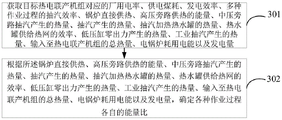
step 301: acquiring plant power consumption rate, power supply coal consumption, power generation efficiency, steam extraction efficiency in various operation processes, direct boiler heat supply, high-pressure bypass heat supply energy, heat generated by medium-pressure bypass steam extraction, heat generated by steam extraction to heat a hot water tank, efficiency of the hot water tank to supply a heat network, heat generated by zero output of a low-pressure cylinder, heat generated by industrial steam extraction, total heat input to the cogeneration unit, electric energy consumed by an electric boiler and generated energy corresponding to a target cogeneration unit;
step 302: and determining respective energy ratios of various operation processes according to the energy of direct heat supply and high-pressure bypass heat supply of the boiler, the heat generated by steam extraction of the medium-pressure bypass, the heat generated by steam extraction, the heat of a hot water tank heated by steam extraction, the efficiency of the hot water tank for supplying heat to a heat supply network, the heat generated by zero output of a low-pressure cylinder, the heat generated by industrial steam extraction, the total heat input to the cogeneration unit, the electric energy consumed by the electric boiler and the generated energy.
1) For the heating process of the electric boiler after power generation, the energy ratio alpha can be determined according to the following formula EH :

Wherein, W EB Representing the electric energy consumed by the electric boiler; w represents the generated energy of the cogeneration unit; order to L EB Representing the ratio of the electric energy consumption of the electric boiler to the total power generation; alpha is alpha E The ratio of the energy used for generating the electric energy by the unit to the total heat of the steam turbine is represented and calculated according to the energy ratio of other processes.
2) For a boiler direct heating process, the energy ratio α can be determined according to the following formula DH :

Wherein Q is T The total heat quantity of the main steam and the reheated steam input to the steam turbine is represented, namely the total heat quantity input to the cogeneration unit; q DH Represents the energy of direct heat supply of the boiler; q HBP Representing the energy of the high pressure bypass heating.
The total heat Q input to the turbine can be determined according to the following formula T :
Q T =H sm D sm +H rhh D rhc -H fw D sm -H rhc D rhc -∑H sw D sw
3) For a medium pressure by-pass steam heating process, the energy ratio α can be determined according to the following equation IBH :

Wherein Q is IBH Representing the heat supplied from the intermediate pressure bypass extraction, i.e., the heat generated by the intermediate pressure bypass extraction.
4) For the steam extraction and heat supply process, the energy ratio alpha can be determined according to the following formula DRH :

5) For the steam extraction used in the heating process of a hot water boiler, the energy ratio alpha can be determined according to the following formula DRWB :

Wherein Q is DRWB Represents the heat quantity of the hot water tank heated by the extraction steam, namely the heat quantity of the hot water tank heated by the extraction steam;
6) for the zero-output steam extraction and heat supply process of the low-pressure cylinder, the energy ratio alpha can be determined according to the following formula LP :

7) For an industrial extraction process, the energy ratio α can be determined according to the following formula DS :

8) The energy ratio alpha of the power generation process can be determined according to the following formula E :
α E =1-α DH -α DRH -α DRWB -α IBH -α LP -α DS
Since a part of the produced electricity is used in the electric boiler, the energy ratio of the electricity finally delivered to the power grid is less than alpha E Determining the energy ratio of the electricity finally delivered to the grid as
To further improve the energy efficiency of the decoupling of heat and power and improve the economy of operation of the cogeneration unit, referring to fig. 4, in one embodiment of the present application, step 203 comprises:
step 401: obtaining a plurality of cogeneration routes to be screened based on the power generation process and the various operation processes, wherein each cogeneration route to be screened comprises: a power generation process and at least one operation process; the operation processes corresponding to all the cogeneration routes to be screened are different.
Specifically, for each cogeneration line to be screened, the energy ratio α of the power generation process in the line to be screened is E Is (1-sum of energy ratios of other individual processes).
Step 402: and carrying out weighted averaging processing according to the energy efficiency evaluation result of the power generation process, the energy efficiency evaluation result of each operation process in each cogeneration route to be screened and the energy ratio, and determining the energy efficiency evaluation result of the cogeneration route to be screened.
Step 403: and determining the screened cogeneration route with the highest energy efficiency evaluation result value as a thermoelectric decoupling route corresponding to the target cogeneration unit.
For example, one cogeneration line includes: and in the power generation process, the direct heat supply, the steam extraction hot water tank, the electric boiler, the low-pressure cylinder zero-output heat supply process and the industrial steam extraction process, the energy recovery ratio corresponding to the cogeneration route is obtained by weighted average calculation of the recovery ratios of all the processes according to the energy ratio. Considering the process of reducing the power generation amount by the electric boiler, the overall energy recovery ratio is as follows:

according to the mode of plant power rate Substituting COP values of various cogeneration subprocesses into the formula and finishing to obtain:

wherein alpha is E Energy ratio, alpha, representing the power generation process EH Represents the energy ratio, alpha, for an electric boiler (electric heating hot water tank) after power generation DH Representing the direct energy ratio (including high side direct heat supply) of the boiler, alpha IBH Represents the medium pressure bypass steam energy ratio, alpha DRH Expressing the steam extraction energy ratio, alpha DRWB Represents the energy ratio of the steam extraction to the hot water boiler (i.e., the energy ratio of the steam extraction to the hot water tank), alpha LP Indicating the zero-output steam extraction energy ratio, alpha, of the low pressure cylinder DS Representing the industrial extraction energy ratio; b represents the power supply coal consumption; eta T Representing the generating efficiency of the cogeneration unit; eta IBH Expressing extraction efficiency, eta, of the medium pressure bypass steam DRH The steam extraction efficiency of the steam extraction heating steam is shown; eta DRWB Steam for indicating steam extraction and hot water supply boilerThe steam extraction efficiency of the steam extraction system; eta LP The steam extraction efficiency of the low pressure cylinder is shown when the low pressure cylinder has zero output; eta EB Representing the efficiency of the electric boiler to heat the water tank to the final supply heat to the heat supply network; l is EB The ratio of the electricity consumed by the electric boiler to the total power generation is expressed and can be called the power consumption rate of the electric boiler; l is cyr Representing the power consumption rate of the branch plant for the heat supply process; l is cyf Representing the power rate of the branch plant for the power generation process; l is cyr And L cyf The sum is the plant power rate.
To further explain the scheme, the application also provides an application example of the heat and power decoupling method based on the cogeneration unit, which is specifically described as follows:
1) boiler direct heat supply Q DH And high pressure bypass heating Q HBP The energy of the boiler is uniformly calculated according to the direct heat supply of the boiler;

wherein Q is T The main steam and the reheat steam are input into the total heat of the cogeneration unit; alpha is alpha DH The direct energy ratio of the boiler (including direct heat supply of high side) is realized.
Q T =H sm D sm +H rhh D rhc -H fw D sm -H rhc D rhc -∑H sw D sw
Or according to the input heat of the boiler, the fuel quantity of the boiler, the efficiency of a pipeline and the like
Q T =BQ net,ar η B η P
The two are equivalent, and the choice is convenient to use.
2) The medium-pressure bypass heat supply, the steam extraction heat hot water tank and the low-pressure cylinder zero-output are divided into optical axis/cylinder cutting unification according to the steam extraction heat supply consideration, and the hot water boiler considers the heat dissipation loss and respectively calculates; thus, the heat and energy ratios of each part are respectively as follows:
medium pressure bypass steam energy ratio: wherein Q is IBH Representing the heat supplied from the intermediate pressure bypass extraction.
Extraction energy ratio: wherein Q is DRH Representing the heat supplied from the extraction.
Energy ratio of the steam extraction heating hot water tank: wherein Q is DRWB Representing the heat of heating the water tank from the extraction steam, eta WB Efficiency of the final supply of the heating network to the hot water tank.
Low pressure cylinder zero output steam extraction energy ratio:
steam extraction efficiency eta of steam exhaust position of intermediate pressure cylinder IBH Steam extraction efficiency eta of steam extraction heating part DRH Steam extraction efficiency eta at the position of the steam extraction and heat removal water tank DRWB Steam extraction efficiency eta of steam exhaust position of intermediate pressure cylinder LP 。
3) For industrial extraction of steam, its heat content The final sum of the fractions is 1, i.e.:
1=α E +α DH +α DRH +α DS +α DRWB +α IBH +α LP
4) for an electric boiler (electrically heated water heating tank), the fraction α thereof EH As part of the power generation process, namely:

wherein, W EB The electric boiler consumes electric energy, and W is the power generation capacity of the cogeneration unit, L EB For electric boiler consumptionPlant power rate.
According to the characteristics, the combined heat and power generation unit with the heat and power decoupling function determines the energy recovery ratio of the target combined heat and power generation unit according to the plant power consumption rate, the power generation efficiency of the combined heat and power generation unit, the energy recovery ratio of the heat pump and each energy ratio, and the energy recovery ratio calculation formula including all the conditions is as follows:

wherein alpha is E Energy ratio, alpha, representing the power generation process DH Representing the direct energy ratio (including high side direct heat supply) of the boiler, alpha IBH Represents the medium pressure bypass steam energy ratio, alpha DRH Expressing the steam extraction energy ratio, alpha DRWB Represents the energy ratio of the steam extraction to the hot water boiler (i.e., the energy ratio of the steam extraction to the hot water tank), alpha LP Indicating the zero-output steam extraction energy ratio, alpha, of the low pressure cylinder DS Representing the industrial extraction energy ratio; b represents the power supply coal consumption; eta T Representing the generating efficiency of the cogeneration unit; eta IBH Expressing extraction efficiency, eta, of the medium pressure bypass steam DRH The steam extraction efficiency of the steam extraction heating steam is shown; eta DRWB The steam extraction efficiency of the steam for the steam extraction and hot water supply boiler is shown; eta LP The steam extraction efficiency of the steam at the inlet of the low-pressure cylinder is shown when the low-pressure cylinder has zero output; eta EB Represents the overall efficiency of the electric boiler from electric heating to heat supply; l is cyr Representing the power consumption rate of the branch plant for the heat supply process; l is cyf Representing the power rate of the branch plant for the power generation process; l is a radical of an alcohol cyr And L cyf The sum is the plant power rate.
The evaluation method comprises the following steps:
1) according to a thermoelectric decoupling method, several of direct boiler heat supply (including high bypass direct heat supply), medium-pressure bypass energy ratio, steam extraction energy ratio, ratio of steam extraction to hot water tank, electric heating hot water tank ratio, low-pressure cylinder zero-output steam extraction energy ratio and industrial steam extraction energy ratio are adopted for determining a certain thermoelectric cogeneration route.
2) Calculating the energy recovery ratio according to different working conditions;
3) evaluation was performed based on the energy recovery ratio, and a technique having a large energy recovery ratio prevails.
In one example, cogeneration line 1: the final cogeneration scheme is "power generation process + steam extraction heat supply + steam extraction heating hot water tank", then:

cogeneration route 2: the final cogeneration scheme is "power generation process + steam extraction and heat supply + electric boiler (electric heating hot water tank)", then:

cogeneration route 3: and finally, the cogeneration scheme is 'power generation process + zero output of low-pressure cylinder', and then:

in these 3 cogeneration routes, the energy ratio α LP The maximum can reach about 70%, the steam extraction efficiency is higher by about 35%, the coal consumption of power supply can be reduced to 160gce/kWh, and the power consumption of a heat supply plant is assumed to be 1% because the energy recovery ratio is about 3.69.
In the cogeneration route 1, because the low-pressure cylinder also has steam to do work, and therefore the same energy ratio is to be achieved, the pressure parameter of the steam extraction heat supply and the heat supply of the hot water boiler must be higher than the steam pressure parameter of the zero output parameter of the low-pressure cylinder (the flow is smaller than the zero output parameter of the low-pressure cylinder), the steam extraction efficiency is assumed to be 37%, meanwhile, because the condenser also has the condensation capacity, the power supply coal consumption is also higher than that of the cogeneration route 1, and the energy recovery ratio is calculated to be 3.43 assuming that the power supply coal consumption is 180gce/kWh, namely, the energy recovery ratio at the moment is not much different from the pure power generation, namely, the overall energy efficiency of the centralized heat supply and the heat supply of the household air conditioners is not much different from the overall energy efficiency of the household air conditioners.
Thermoelectric couplingIn the production line 2, because the low-pressure cylinder and the steam do work, and the same energy ratio is achieved, the pressure parameter of the steam extraction heat supply and the heat supply quantity of the electric boiler (electric heating hot water tank) is higher than the steam pressure parameter of the zero output parameter of the low-pressure cylinder (the flow is smaller than the zero output parameter of the low-pressure cylinder), but because a part of the electricity produced by the unit is also used for heating the hot water tank, the steam extraction flow is smaller than that of the cogeneration line 1, the steam extraction efficiency is assumed to be 36.5%, and 20% of the produced electricity is simultaneously used for producing alpha by the electric boiler (electric heating hot water tank) EH Referring to the cogeneration route 1, when the steam extraction energy ratio is 0.65 and the power generation ratio is 0.35 to obtain the coal consumption 225gce/kWh of power supply, the energy recovery ratio is calculated to be 3.10, namely the energy recovery ratio is lower than the pure power generation, and the centralized heating mode is far lower than the overall energy efficiency of the heating of the residential household air conditioners, because a large amount of heat power only contributes to the energy efficiency ratio of 0.08 and the overall energy efficiency is reduced; and finally, sequentially determining the energy efficiency evaluation results of the cogeneration route from high to low: cogeneration line 3>Cogeneration line 1>>The cogeneration route 2, the optimal decoupling route is the cogeneration route 3.
In terms of software, in order to improve the energy efficiency of the cogeneration unit based on the realization of the decoupling of heat and power, the present application provides an embodiment of the decoupling device based on the cogeneration unit for realizing all or part of the contents in the decoupling method based on the cogeneration unit, and referring to fig. 5, the decoupling route determining device based on the cogeneration unit specifically includes the following contents:
the acquiring module 51 is configured to acquire plant power consumption, power supply coal consumption, power generation efficiency, and energy ratios and steam extraction efficiency corresponding to multiple operation processes, which correspond to the target cogeneration unit;
the determining module 52 is configured to determine an energy efficiency evaluation result of the power generation process of the target cogeneration unit and energy efficiency evaluation results corresponding to various operation processes according to the plant power consumption rate, the power supply coal consumption, the power generation efficiency, and the steam extraction efficiency;
a selecting module 53, configured to select at least one of the various operation processes based on the energy efficiency evaluation result of the power generation process, the energy efficiency evaluation results and the energy ratios corresponding to the various operation processes, and form a cogeneration route with a highest energy efficiency evaluation result value with the power generation process, where the cogeneration route is used as a thermoelectric decoupling route corresponding to the target cogeneration unit;
a thermoelectric decoupling module 54, configured to execute the thermoelectric decoupling route to achieve thermoelectric decoupling of the target cogeneration unit.
Wherein the operation process may include: after power generation, the power generation device is used for an electric boiler heat supply process, a boiler direct heat supply process, a medium-pressure bypass steam heat supply process, a steam extraction process for a hot water boiler heat supply process, a low-pressure cylinder zero-output steam extraction heat supply process and an industrial steam extraction process.
In one embodiment of the present application, the obtaining module includes:
the system comprises an acquisition unit, a control unit and a control unit, wherein the acquisition unit is used for acquiring the plant power consumption, the power supply coal consumption, the power generation efficiency, the steam extraction efficiency in various operation processes, the direct heat supply of a boiler, the energy of high-pressure bypass heat supply, the heat generated by medium-pressure bypass steam extraction, the heat generated by steam extraction and heating of a hot water tank, the efficiency of a hot water tank for supplying a heat network, the heat generated by zero output of a low-pressure cylinder, the heat generated by industrial steam extraction, the total heat input to the cogeneration unit, the electric energy consumed by an electric boiler and the generated energy corresponding to a target cogeneration unit;
and the determining unit is used for determining respective energy ratios of various working processes according to the energy of direct heat supply and high-pressure bypass heat supply of the boiler, the heat generated by steam extraction of the medium-pressure bypass, the heat generated by steam extraction to heat the hot water tank, the efficiency of the hot water tank for supplying the hot network, the heat generated by zero output of the low-pressure cylinder, the heat generated by industrial steam extraction, the total heat input to the cogeneration unit, the electric energy consumed by the electric boiler and the generated energy.
In an embodiment of the present application, the selecting module includes:
and the grouping unit is used for obtaining a plurality of cogeneration routes to be screened based on the power generation process and various operation processes, and each cogeneration route to be screened comprises: a power generation process and at least one operation process; the operation processes corresponding to all the cogeneration routes to be screened are different;
the evaluation unit is used for carrying out weighted averaging processing according to the energy efficiency evaluation result of the power generation process, the energy efficiency evaluation result of each operation process in each to-be-screened cogeneration route and the energy ratio, and determining the energy efficiency evaluation result of the to-be-screened cogeneration route;
and the selecting unit is used for determining the screened cogeneration route with the highest energy efficiency evaluation result value as the thermoelectric decoupling route corresponding to the target cogeneration unit.
The embodiments of the decoupling device based on a cogeneration unit provided in this specification can be specifically used for executing the processing procedure of the embodiments of the decoupling method based on a cogeneration unit, and the functions of the embodiments are not described herein again, and reference may be made to the detailed description of the embodiments of the decoupling method based on a cogeneration unit.
In terms of hardware, in order to improve the energy efficiency of the cogeneration unit on the basis of implementing the decoupling of heat and power, the present application provides an embodiment of an electronic device for implementing all or part of the contents in the decoupling method of heat and power based on the cogeneration unit, where the electronic device specifically includes the following contents:
a processor (processor), a memory (memory), a communication Interface (Communications Interface), and a bus; the processor, the memory and the communication interface complete mutual communication through the bus; the communication interface is used for realizing information transmission between the thermoelectric decoupling device based on the cogeneration unit, the user terminal and other related equipment; the electronic device may be a desktop computer, a tablet computer, a mobile terminal, and the like, but the embodiment is not limited thereto. In this embodiment, the electronic device may be implemented with reference to the embodiment of the method for implementing the decoupling based on the cogeneration unit and the embodiment of the device for implementing the decoupling based on the cogeneration unit, which are incorporated herein, and repeated details are not repeated.
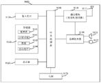
Fig. 6 is a schematic block diagram of a system configuration of an electronic device 9600 according to an embodiment of the present application. As shown in fig. 6, the electronic device 9600 can include a central processor 9100 and a memory 9140; the memory 9140 is coupled to the central processor 9100. Notably, this FIG. 6 is exemplary; other types of structures may also be used in addition to or in place of the structure to implement telecommunications or other functions.
In one or more embodiments of the present application, the decoupling functionality based on the cogeneration units may be integrated into the central processor 9100. The central processor 9100 may be configured to control as follows:
step 201: and acquiring plant power consumption, power supply coal consumption, power generation efficiency, energy ratio and steam extraction efficiency corresponding to various operation processes corresponding to the target cogeneration unit.
Step 202: and determining an energy efficiency evaluation result of the target cogeneration unit in the power generation process and energy efficiency evaluation results corresponding to various operation processes according to the plant power consumption rate, the power supply coal consumption, the power generation efficiency and the steam extraction efficiency.
Step 203: and selecting at least one from various operation processes based on the energy efficiency evaluation result of the power generation process, the energy efficiency evaluation results and the energy ratio corresponding to the various operation processes, and forming a cogeneration route with the highest energy efficiency evaluation result value with the power generation process as a cogeneration decoupling route corresponding to the target cogeneration unit.
Step 204: and executing the heat and power decoupling route to realize the heat and power decoupling of the target combined heat and power generation unit.
As can be seen from the above description, the electronic device provided in the embodiments of the present application can improve the energy efficiency of the cogeneration unit on the basis of implementing the decoupling of heat and power.
In another embodiment, the decoupling device based on the cogeneration unit can be configured separately from the central processor 9100, for example, the decoupling device based on the cogeneration unit can be configured as a chip connected to the central processor 9100, and the decoupling function based on the cogeneration unit can be realized by the control of the central processor.
As shown in fig. 6, the electronic device 9600 may further include: a communication module 9110, an input unit 9120, an audio processor 9130, a display 9160, and a power supply 9170. It is noted that the electronic device 9600 also does not necessarily include all of the components shown in fig. 6; further, the electronic device 9600 may further include components not shown in fig. 6, which may be referred to in the art.
As shown in fig. 6, a central processor 9100, sometimes referred to as a controller or operational control, can include a microprocessor or other processor device and/or logic device, which central processor 9100 receives input and controls the operation of the various components of the electronic device 9600.
The memory 9140 can be, for example, one or more of a buffer, a flash memory, a hard drive, a removable media, a volatile memory, a non-volatile memory, or other suitable device. The information relating to the failure may be stored, and a program for executing the information may be stored. And the central processing unit 9100 can execute the program stored in the memory 9140 to realize information storage or processing, or the like.
The input unit 9120 provides input to the central processor 9100. The input unit 9120 is, for example, a key or a touch input device. Power supply 9170 is used to provide power to electronic device 9600. The display 9160 is used for displaying display objects such as images and characters. The display may be, for example, an LCD display, but is not limited thereto.
The memory 9140 can be a solid state memory, e.g., Read Only Memory (ROM), Random Access Memory (RAM), a SIM card, or the like. There may also be a memory that holds information even when power is off, can be selectively erased, and is provided with more data, an example of which is sometimes called an EPROM or the like. The memory 9140 could also be some other type of device. Memory 9140 includes a buffer memory 9141 (sometimes referred to as a buffer). The memory 9140 may include an application/function storage portion 9142, the application/function storage portion 9142 being used for storing application programs and function programs or for executing a flow of operations of the electronic device 9600 by the central processor 9100.
The memory 9140 can also include a data store 9143, the data store 9143 being used to store data, such as contacts, digital data, pictures, sounds, and/or any other data used by an electronic device. The driver storage portion 9144 of the memory 9140 may include various drivers for the electronic device for communication functions and/or for performing other functions of the electronic device (e.g., messaging applications, contact book applications, etc.).
The communication module 9110 is a transmitter/receiver 9110 that transmits and receives signals via an antenna 9111. The communication module (transmitter/receiver) 9110 is coupled to the central processor 9100 to provide input signals and receive output signals, which may be the same as in the case of a conventional mobile communication terminal.
Based on different communication technologies, a plurality of communication modules 9110, such as a cellular network module, a bluetooth module, and/or a wireless local area network module, may be provided in the same electronic device. The communication module (transmitter/receiver) 9110 is also coupled to a speaker 9131 and a microphone 9132 via an audio processor 9130 to provide audio output via the speaker 9131 and receive audio input from the microphone 9132, thereby implementing ordinary telecommunications functions. The audio processor 9130 may include any suitable buffers, decoders, amplifiers and so forth. In addition, the audio processor 9130 is also coupled to the central processor 9100, thereby enabling recording locally through the microphone 9132 and enabling locally stored sounds to be played through the speaker 9131.
As can be seen from the above description, the electronic device provided in the embodiments of the present application can improve the energy efficiency of the cogeneration unit on the basis of implementing the decoupling of heat and power.
Embodiments of the present application further provide a computer-readable storage medium capable of implementing all the steps in the method for decoupling heat and power based on a cogeneration unit in the above embodiments, where the computer-readable storage medium stores thereon a computer program, and the computer program implements all the steps of the method for decoupling heat and power based on a cogeneration unit in the above embodiments when executed by a processor, for example, the processor implements the following steps when executing the computer program:
step 201: and acquiring plant power consumption, power supply coal consumption, power generation efficiency, energy ratio and steam extraction efficiency corresponding to various operation processes corresponding to the target cogeneration unit.
Step 202: and determining an energy efficiency evaluation result of the target cogeneration unit in the power generation process and energy efficiency evaluation results corresponding to various operation processes according to the plant power consumption rate, the power supply coal consumption, the power generation efficiency and the steam extraction efficiency.
Step 203: and selecting at least one from various operation processes based on the energy efficiency evaluation result of the power generation process, the energy efficiency evaluation results and the energy ratio corresponding to the various operation processes, and forming a cogeneration route with the highest energy efficiency evaluation result value with the power generation process as a cogeneration decoupling route corresponding to the target cogeneration unit.
Step 204: and executing the heat and power decoupling route to realize the heat and power decoupling of the target combined heat and power generation unit.
As can be seen from the above description, the computer-readable storage medium provided in the embodiments of the present application can improve the energy efficiency of the cogeneration unit on the basis of implementing the decoupling of heat and power.
In the present application, each embodiment of the method is described in a progressive manner, and the same and similar parts among the embodiments are referred to each other, and each embodiment focuses on the differences from the other embodiments. Reference is made to the description of the method embodiments.
As will be appreciated by one skilled in the art, embodiments of the present application may be provided as a method, system, or computer program product. Accordingly, the present application may take the form of an entirely hardware embodiment, an entirely software embodiment or an embodiment combining software and hardware aspects. Furthermore, the present application may take the form of a computer program product embodied on one or more computer-usable storage media (including, but not limited to, disk storage, CD-ROM, optical storage, and the like) having computer-usable program code embodied therein.
The present application is described with reference to flowchart illustrations and/or block diagrams of methods, apparatus (systems), and computer program products according to embodiments of the application. It will be understood that each flow and/or block of the flow diagrams and/or block diagrams, and combinations of flows and/or blocks in the flow diagrams and/or block diagrams, can be implemented by computer program instructions. These computer program instructions may be provided to a processor of a general purpose computer, special purpose computer, embedded processor, or other programmable data processing apparatus to produce a machine, such that the instructions, which execute via the processor of the computer or other programmable data processing apparatus, create means for implementing the functions specified in the flowchart flow or flows and/or block diagram block or blocks.
These computer program instructions may also be stored in a computer-readable memory that can direct a computer or other programmable data processing apparatus to function in a particular manner, such that the instructions stored in the computer-readable memory produce an article of manufacture including instruction means which implement the function specified in the flowchart flow or flows and/or block diagram block or blocks.
These computer program instructions may also be loaded onto a computer or other programmable data processing apparatus to cause a series of operational steps to be performed on the computer or other programmable apparatus to produce a computer implemented process such that the instructions which execute on the computer or other programmable apparatus provide steps for implementing the functions specified in the flowchart flow or flows and/or block diagram block or blocks.
The principle and the implementation mode of the present application are explained by applying specific embodiments in the present application, and the description of the above embodiments is only used to help understanding the method and the core idea of the present application; meanwhile, for a person skilled in the art, according to the idea of the present application, the specific implementation manner and the application scope may be changed, and in summary, the content of the present specification should not be construed as a limitation to the present application.
Claims (10)
1. A heat and power decoupling method based on a cogeneration unit is characterized by comprising the following steps:
acquiring plant power consumption rate, power supply coal consumption, power generation efficiency, energy ratio and steam extraction efficiency corresponding to various operation processes corresponding to a target cogeneration unit;
determining an energy efficiency evaluation result of the target cogeneration unit in the power generation process and energy efficiency evaluation results corresponding to various operation processes according to the plant power consumption rate, the power supply coal consumption, the power generation efficiency and the steam extraction efficiency;
selecting at least one from various operation processes based on the energy efficiency evaluation result of the power generation process, the energy efficiency evaluation results and the energy ratios corresponding to the various operation processes, and forming a cogeneration route with the highest energy efficiency evaluation result value with the power generation process as a cogeneration decoupling route corresponding to the target cogeneration unit;
and executing the heat and power decoupling route to realize the heat and power decoupling of the target combined heat and power generation unit.
2. Cogeneration unit based decoupling method of heat and power according to claim 1,
the operation process comprises the following steps: after power generation, the power generation device is used for an electric boiler heat supply process, a boiler direct heat supply process, a medium-pressure bypass steam heat supply process, a steam extraction process for a hot water boiler heat supply process, a low-pressure cylinder zero-output steam extraction heat supply process and an industrial steam extraction process.
3. The method for decoupling heat and power based on the cogeneration unit according to claim 1, wherein the obtaining of the plant power rate, the power supply coal consumption, the power generation efficiency, the energy ratio and the steam extraction efficiency corresponding to the multiple operation processes corresponding to the target cogeneration unit comprises:
acquiring plant power consumption rate, power supply coal consumption, power generation efficiency, steam extraction efficiency in various operation processes, direct boiler heat supply, high-pressure bypass heat supply energy, heat generated by medium-pressure bypass steam extraction, heat generated by steam extraction to heat a hot water tank, efficiency of the hot water tank to supply a heat network, heat generated by zero output of a low-pressure cylinder, heat generated by industrial steam extraction, total heat input to the cogeneration unit, electric energy consumed by an electric boiler and generated energy corresponding to a target cogeneration unit;
and determining respective energy ratios of various operation processes according to the energy of direct heat supply and high-pressure bypass heat supply of the boiler, the heat generated by steam extraction of the medium-pressure bypass, the heat generated by steam extraction, the heat of a hot water tank heated by steam extraction, the efficiency of the hot water tank for supplying heat to a heat supply network, the heat generated by zero output of a low-pressure cylinder, the heat generated by industrial steam extraction, the total heat input to the cogeneration unit, the electric energy consumed by the electric boiler and the generated energy.
4. The method for decoupling heat and power based on a cogeneration unit according to claim 1, wherein the selecting at least one of the various processes based on the energy efficiency evaluation result of the power generation process, the energy efficiency evaluation result and the energy ratio corresponding to each of the various processes, and forming a cogeneration route having the highest energy efficiency evaluation result value with the power generation process as the decoupling heat and power corresponding to the target cogeneration unit comprises:
obtaining a plurality of cogeneration routes to be screened based on the power generation process and the various operation processes, wherein each cogeneration route to be screened comprises: a power generation process and at least one operation process; the operation processes corresponding to all the cogeneration routes to be screened are different;
carrying out weighted averaging processing according to the energy efficiency evaluation result of the power generation process, the energy efficiency evaluation result of each operation process in each cogeneration route to be screened and the energy ratio, and determining the energy efficiency evaluation result of the cogeneration route to be screened;
and determining the screened cogeneration route with the highest energy efficiency evaluation result value as a thermoelectric decoupling route corresponding to the target cogeneration unit.
5. A kind of thermoelectricity decoupling zero device based on combined heat and power generating unit, characterized by that, comprising:
the system comprises an acquisition module, a control module and a control module, wherein the acquisition module is used for acquiring plant power consumption, power supply coal consumption, power generation efficiency, energy ratio and steam extraction efficiency corresponding to various operation processes corresponding to a target cogeneration unit;
the determining module is used for determining an energy efficiency evaluation result of the power generation process of the target cogeneration unit and energy efficiency evaluation results corresponding to various operation processes according to the plant power consumption rate, the power supply coal consumption, the power generation efficiency and the steam extraction efficiency;
the selection module is used for selecting at least one of various operation processes based on the energy efficiency evaluation result of the power generation process, the energy efficiency evaluation results and the energy ratios corresponding to the various operation processes, and forming a combined heat and power generation route with the power generation process, wherein the combined heat and power generation route has the highest energy efficiency evaluation result value and is used as a combined heat and power decoupling route corresponding to the target combined heat and power generation unit;
and the thermoelectric decoupling module is used for executing the thermoelectric decoupling route so as to realize the thermoelectric decoupling of the target cogeneration unit.
6. Cogeneration unit based heat and power decoupling device according to claim 5,
the operation process comprises the following steps: after power generation, the power generation device is used for an electric boiler heat supply process, a boiler direct heat supply process, a medium-pressure bypass steam heat supply process, a steam extraction process for a hot water boiler heat supply process, a low-pressure cylinder zero-output steam extraction heat supply process and an industrial steam extraction process.
7. The cogeneration unit based heat and power decoupling apparatus of claim 5, wherein said acquisition module comprises:
the system comprises an acquisition unit, a control unit and a control unit, wherein the acquisition unit is used for acquiring the plant power consumption, the power supply coal consumption, the power generation efficiency, the steam extraction efficiency in various operation processes, the direct heat supply of a boiler, the energy of high-pressure bypass heat supply, the heat generated by medium-pressure bypass steam extraction, the heat generated by steam extraction and heating of a hot water tank, the efficiency of a hot water tank for supplying a heat network, the heat generated by zero output of a low-pressure cylinder, the heat generated by industrial steam extraction, the total heat input to the cogeneration unit, the electric energy consumed by an electric boiler and the generated energy corresponding to a target cogeneration unit;
and the determining unit is used for determining respective energy ratios of various working processes according to the energy of direct heat supply and high-pressure bypass heat supply of the boiler, the heat generated by steam extraction of the medium-pressure bypass, the heat generated by steam extraction to heat the hot water tank, the efficiency of the hot water tank for supplying the hot network, the heat generated by zero output of the low-pressure cylinder, the heat generated by industrial steam extraction, the total heat input to the cogeneration unit, the electric energy consumed by the electric boiler and the generated energy.
8. The cogeneration unit-based heat and power decoupling device of claim 5, wherein said selection module comprises:
and the grouping unit is used for obtaining a plurality of cogeneration routes to be screened based on the power generation process and various operation processes, and each cogeneration route to be screened comprises: a power generation process and at least one operation process; the operation processes corresponding to all the cogeneration routes to be screened are different;
the evaluation unit is used for carrying out weighted averaging processing according to the energy efficiency evaluation result of the power generation process, the energy efficiency evaluation result of each operation process in each to-be-screened cogeneration route and the energy ratio, and determining the energy efficiency evaluation result of the to-be-screened cogeneration route;
and the selecting unit is used for determining the screened cogeneration route with the highest energy efficiency evaluation result value as the thermoelectric decoupling route corresponding to the target cogeneration unit.
9. An electronic device comprising a memory, a processor and a computer program stored on the memory and executable on the processor, wherein the processor implements the method for decoupling heat and power based on a cogeneration unit according to any one of claims 1 to 4 when executing the program.
10. A computer readable storage medium having stored thereon computer instructions, wherein the instructions when executed implement the method for decoupling heat and power based on a cogeneration unit of any one of claims 1 to 4.
Priority Applications (1)
| Application Number | Priority Date | Filing Date | Title |
|---|---|---|---|
| CN202210573603.5A CN114893262A (en) | 2022-05-25 | 2022-05-25 | Thermoelectric decoupling method and device based on cogeneration unit |
Applications Claiming Priority (1)
| Application Number | Priority Date | Filing Date | Title |
|---|---|---|---|
| CN202210573603.5A CN114893262A (en) | 2022-05-25 | 2022-05-25 | Thermoelectric decoupling method and device based on cogeneration unit |
Publications (1)
| Publication Number | Publication Date |
|---|---|
| CN114893262A true CN114893262A (en) | 2022-08-12 |
Family
ID=82726909
Family Applications (1)
| Application Number | Title | Priority Date | Filing Date |
|---|---|---|---|
| CN202210573603.5A Pending CN114893262A (en) | 2022-05-25 | 2022-05-25 | Thermoelectric decoupling method and device based on cogeneration unit |
Country Status (1)
| Country | Link |
|---|---|
| CN (1) | CN114893262A (en) |
Citations (7)
| Publication number | Priority date | Publication date | Assignee | Title |
|---|---|---|---|---|
| WO2017204758A1 (en) * | 2016-05-27 | 2017-11-30 | Polkar Orman Urunleri Ve Enerji A. S | Producing electrical energy using reversible cogeneration-w (chp-w) method instead of cogeneration (chp) |
| CN207813675U (en) * | 2017-11-30 | 2018-09-04 | 华电电力科学研究院 | A kind of co-generation unit for carrying on the back heat supply for solidifying pumping |
| CN209621420U (en) * | 2019-02-02 | 2019-11-12 | 华电电力科学研究院有限公司 | A kind of heat supply for Combined cycle gas-steam turbine unit and power peak regulation coupled system |
| CN113240280A (en) * | 2021-05-14 | 2021-08-10 | 华电电力科学研究院有限公司 | Heat economy evaluation method for cogeneration unit |
| CN113468732A (en) * | 2021-06-22 | 2021-10-01 | 西安热工研究院有限公司 | System and method for determining production cost for heat supply of steam extraction heat supply unit |
| CN113627033A (en) * | 2021-08-27 | 2021-11-09 | 西安热工研究院有限公司 | Heat preservation and power regulation capacity improvement method and system for heating cogeneration unit |
| CN113822496A (en) * | 2021-10-27 | 2021-12-21 | 杭州英集动力科技有限公司 | Multi-unit thermal power plant heat supply mode and parameter online optimization method |
-
2022
- 2022-05-25 CN CN202210573603.5A patent/CN114893262A/en active Pending
Patent Citations (7)
| Publication number | Priority date | Publication date | Assignee | Title |
|---|---|---|---|---|
| WO2017204758A1 (en) * | 2016-05-27 | 2017-11-30 | Polkar Orman Urunleri Ve Enerji A. S | Producing electrical energy using reversible cogeneration-w (chp-w) method instead of cogeneration (chp) |
| CN207813675U (en) * | 2017-11-30 | 2018-09-04 | 华电电力科学研究院 | A kind of co-generation unit for carrying on the back heat supply for solidifying pumping |
| CN209621420U (en) * | 2019-02-02 | 2019-11-12 | 华电电力科学研究院有限公司 | A kind of heat supply for Combined cycle gas-steam turbine unit and power peak regulation coupled system |
| CN113240280A (en) * | 2021-05-14 | 2021-08-10 | 华电电力科学研究院有限公司 | Heat economy evaluation method for cogeneration unit |
| CN113468732A (en) * | 2021-06-22 | 2021-10-01 | 西安热工研究院有限公司 | System and method for determining production cost for heat supply of steam extraction heat supply unit |
| CN113627033A (en) * | 2021-08-27 | 2021-11-09 | 西安热工研究院有限公司 | Heat preservation and power regulation capacity improvement method and system for heating cogeneration unit |
| CN113822496A (en) * | 2021-10-27 | 2021-12-21 | 杭州英集动力科技有限公司 | Multi-unit thermal power plant heat supply mode and parameter online optimization method |
Similar Documents
| Publication | Publication Date | Title |
|---|---|---|
| CN109472401B (en) | Method, device, equipment and storage medium for determining distributed energy supply operation strategy | |
| CN109741110B (en) | Opportunity constraint planning-based wind-hydrogen system joint optimization modeling method | |
| CN111159624B (en) | Method for calculating heat supply coal consumption rate of new steam and steam extraction combined heat supply unit | |
| Amiralipour et al. | Potential analysis and technical-economic optimization of conversion of steam power plant into combined water and power | |
| CN112070358A (en) | Method and system for determining electric load adjustment interval of low-vacuum heat supply unit | |
| Fernandez et al. | Transcritical carbon dioxide charge-discharge energy storage with integration of solar energy | |
| CN114862241A (en) | Energy efficiency evaluation method and device for extraction condensing type cogeneration unit | |
| CN113205208B (en) | An efficiency and energy efficiency evaluation method of a comprehensive energy system accounting for primary energy permeability, wherein the efficiency and energy efficiency evaluation method comprises 15794 | |
| CN114893262A (en) | Thermoelectric decoupling method and device based on cogeneration unit | |
| Ivanova et al. | Optimisation of combined cycle gas turbine power plant in intraday market: Riga CHP-2 example | |
| CN113435659A (en) | Scene analysis-based two-stage optimized operation method and system for comprehensive energy system | |
| CN111463773A (en) | Energy management optimization method and device for regional comprehensive energy system | |
| CN115222147A (en) | Method, system and equipment for optimizing production capacity of distributed energy equipment | |
| CN110827057A (en) | Thermoelectric heat return method and device for calculating heat price cost | |
| Siddiqui | Optimal control of distributed energy resources and demand response under uncertainty | |
| CN114997079A (en) | Method and device for determining steam pressure of back pressure steam turbine | |
| CN114862240A (en) | Energy efficiency evaluation method and device for cogeneration unit | |
| CN114626624A (en) | Comprehensive energy system electric-heat combined optimization scheduling method considering heat load conversion | |
| CN116412009A (en) | Thermal power unit depth peak shaving system, method and device | |
| CN114424128A (en) | Modeling method and device of nonlinear model and storage medium | |
| El-Khozondar et al. | Investigating the water consumption for electricity generation at Turkish power plants | |
| CN110796481A (en) | Thermoelectric power return method and device for calculating heat price cost | |
| CN110148064A (en) | Real-time new energy based on the response of stimulable type integration requirement assists consumption method | |
| CN117060492B (en) | Optimization method and equipment for gas-electricity coupling system considering air pressure fluctuation characteristic of pipeline | |
| CN109523167B (en) | Method for evaluating influence of turbine through-flow efficiency on unit output and terminal equipment |
Legal Events
| Date | Code | Title | Description |
|---|---|---|---|
| PB01 | Publication | ||
| PB01 | Publication | ||
| SE01 | Entry into force of request for substantive examination | ||
| SE01 | Entry into force of request for substantive examination |