CN114872280A - Precision injection mold capable of achieving rapid injection molding - Google Patents
Precision injection mold capable of achieving rapid injection molding Download PDFInfo
- Publication number
- CN114872280A CN114872280A CN202210594220.6A CN202210594220A CN114872280A CN 114872280 A CN114872280 A CN 114872280A CN 202210594220 A CN202210594220 A CN 202210594220A CN 114872280 A CN114872280 A CN 114872280A
- Authority
- CN
- China
- Prior art keywords
- mounting
- injection molding
- limiting
- plate
- injection mold
- Prior art date
- Legal status (The legal status is an assumption and is not a legal conclusion. Google has not performed a legal analysis and makes no representation as to the accuracy of the status listed.)
- Pending
Links
- 238000001746 injection moulding Methods 0.000 title claims abstract description 51
- 238000002347 injection Methods 0.000 title claims abstract description 46
- 239000007924 injection Substances 0.000 title claims abstract description 46
- 238000009434 installation Methods 0.000 claims abstract description 35
- 230000007246 mechanism Effects 0.000 claims abstract description 24
- 238000001816 cooling Methods 0.000 claims description 21
- XLYOFNOQVPJJNP-UHFFFAOYSA-N water Substances O XLYOFNOQVPJJNP-UHFFFAOYSA-N 0.000 claims description 13
- 239000007788 liquid Substances 0.000 claims description 12
- 239000004033 plastic Substances 0.000 claims description 4
- 229920003023 plastic Polymers 0.000 claims description 4
- 238000000034 method Methods 0.000 abstract description 18
- 230000008569 process Effects 0.000 abstract description 16
- 230000005540 biological transmission Effects 0.000 abstract description 14
- 230000000694 effects Effects 0.000 abstract description 8
- 239000003292 glue Substances 0.000 description 8
- 238000004519 manufacturing process Methods 0.000 description 4
- 238000000465 moulding Methods 0.000 description 3
- 238000007493 shaping process Methods 0.000 description 3
- 238000003860 storage Methods 0.000 description 3
- 239000002826 coolant Substances 0.000 description 2
- 238000003754 machining Methods 0.000 description 2
- 238000012986 modification Methods 0.000 description 2
- 230000004048 modification Effects 0.000 description 2
- 230000009471 action Effects 0.000 description 1
- 230000009286 beneficial effect Effects 0.000 description 1
- 230000002146 bilateral effect Effects 0.000 description 1
- 230000003139 buffering effect Effects 0.000 description 1
- 239000000110 cooling liquid Substances 0.000 description 1
- 230000007547 defect Effects 0.000 description 1
- 238000010586 diagram Methods 0.000 description 1
- 239000012530 fluid Substances 0.000 description 1
- 230000006872 improvement Effects 0.000 description 1
- 239000000203 mixture Substances 0.000 description 1
- 239000002991 molded plastic Substances 0.000 description 1
- 239000000243 solution Substances 0.000 description 1
Images


Classifications
-
- B—PERFORMING OPERATIONS; TRANSPORTING
- B29—WORKING OF PLASTICS; WORKING OF SUBSTANCES IN A PLASTIC STATE IN GENERAL
- B29C—SHAPING OR JOINING OF PLASTICS; SHAPING OF MATERIAL IN A PLASTIC STATE, NOT OTHERWISE PROVIDED FOR; AFTER-TREATMENT OF THE SHAPED PRODUCTS, e.g. REPAIRING
- B29C45/00—Injection moulding, i.e. forcing the required volume of moulding material through a nozzle into a closed mould; Apparatus therefor
- B29C45/17—Component parts, details or accessories; Auxiliary operations
- B29C45/26—Moulds
-
- B—PERFORMING OPERATIONS; TRANSPORTING
- B29—WORKING OF PLASTICS; WORKING OF SUBSTANCES IN A PLASTIC STATE IN GENERAL
- B29C—SHAPING OR JOINING OF PLASTICS; SHAPING OF MATERIAL IN A PLASTIC STATE, NOT OTHERWISE PROVIDED FOR; AFTER-TREATMENT OF THE SHAPED PRODUCTS, e.g. REPAIRING
- B29C45/00—Injection moulding, i.e. forcing the required volume of moulding material through a nozzle into a closed mould; Apparatus therefor
- B29C45/17—Component parts, details or accessories; Auxiliary operations
- B29C45/40—Removing or ejecting moulded articles
- B29C45/4005—Ejector constructions; Ejector operating mechanisms
-
- B—PERFORMING OPERATIONS; TRANSPORTING
- B29—WORKING OF PLASTICS; WORKING OF SUBSTANCES IN A PLASTIC STATE IN GENERAL
- B29C—SHAPING OR JOINING OF PLASTICS; SHAPING OF MATERIAL IN A PLASTIC STATE, NOT OTHERWISE PROVIDED FOR; AFTER-TREATMENT OF THE SHAPED PRODUCTS, e.g. REPAIRING
- B29C45/00—Injection moulding, i.e. forcing the required volume of moulding material through a nozzle into a closed mould; Apparatus therefor
- B29C45/17—Component parts, details or accessories; Auxiliary operations
- B29C45/64—Mould opening, closing or clamping devices
- B29C45/66—Mould opening, closing or clamping devices mechanical
-
- B—PERFORMING OPERATIONS; TRANSPORTING
- B29—WORKING OF PLASTICS; WORKING OF SUBSTANCES IN A PLASTIC STATE IN GENERAL
- B29C—SHAPING OR JOINING OF PLASTICS; SHAPING OF MATERIAL IN A PLASTIC STATE, NOT OTHERWISE PROVIDED FOR; AFTER-TREATMENT OF THE SHAPED PRODUCTS, e.g. REPAIRING
- B29C45/00—Injection moulding, i.e. forcing the required volume of moulding material through a nozzle into a closed mould; Apparatus therefor
- B29C45/17—Component parts, details or accessories; Auxiliary operations
- B29C45/72—Heating or cooling
- B29C45/73—Heating or cooling of the mould
- B29C45/7312—Construction of heating or cooling fluid flow channels
-
- F—MECHANICAL ENGINEERING; LIGHTING; HEATING; WEAPONS; BLASTING
- F16—ENGINEERING ELEMENTS AND UNITS; GENERAL MEASURES FOR PRODUCING AND MAINTAINING EFFECTIVE FUNCTIONING OF MACHINES OR INSTALLATIONS; THERMAL INSULATION IN GENERAL
- F16F—SPRINGS; SHOCK-ABSORBERS; MEANS FOR DAMPING VIBRATION
- F16F15/00—Suppression of vibrations in systems; Means or arrangements for avoiding or reducing out-of-balance forces, e.g. due to motion
- F16F15/02—Suppression of vibrations of non-rotating, e.g. reciprocating systems; Suppression of vibrations of rotating systems by use of members not moving with the rotating systems
- F16F15/04—Suppression of vibrations of non-rotating, e.g. reciprocating systems; Suppression of vibrations of rotating systems by use of members not moving with the rotating systems using elastic means
- F16F15/06—Suppression of vibrations of non-rotating, e.g. reciprocating systems; Suppression of vibrations of rotating systems by use of members not moving with the rotating systems using elastic means with metal springs
- F16F15/067—Suppression of vibrations of non-rotating, e.g. reciprocating systems; Suppression of vibrations of rotating systems by use of members not moving with the rotating systems using elastic means with metal springs using only wound springs
Abstract
The invention provides a precise injection mold for rapid injection molding, which relates to the technical field of injection molds and comprises an installation base, wherein four supporting rods are uniformly and fixedly arranged on one side of the upper surface of the installation base, a transverse plate is fixedly arranged at the top of each supporting rod, a lower mold is arranged on one side of the upper surface of the installation base, an upper mold is movably arranged below the transverse plate, and a driving mechanism for driving the upper mold to move is arranged on the upper surface of the transverse plate. According to the invention, through the meshing transmission between the worm wheel and the worm, the height adjustment of the whole upper die can be completed under the transmission of the transmission belt, the adjustment precision is higher, the position control of the upper die can be more accurate, and the upper die can play a limiting role in the moving process through the matching between the four support rods, the mounting block and the movable mounting sleeve, so that the upper die cannot generate position deviation in the moving process, the injection molding work is more convenient, and the injection molding effect is better.
Description
Technical Field
The invention relates to the technical field of injection molds, in particular to a precise injection mold for rapid injection molding.
Background
Most of plastic products are injection-molded by an injection mold in the production and processing process, and the injection-molded plastic products have the advantages of high production speed, high efficiency, automation realization of operation, accurate product size, easy replacement of products and capability of forming products with complex shapes, and the injection mold plays a crucial role in the injection-molding process, such as the injection mold for rapid injection molding provided by the patent with the application number of 202020077014.4. The mold comprises a mold base, an upper mold, a lower mold, an upper mold cavity, a lower mold cavity, a first glue injection pipeline and a second glue injection pipeline. The vertical first glue injection pipeline that is provided with on last mould, first glue injection pipeline are hopper-shaped structure, with last die cavity intercommunication, are provided with the reposition of redundant personnel pipeline in the bilateral symmetry of first glue injection pipeline, are provided with two second glue injection pipelines in the both sides of first glue injection pipeline, are provided with the drainage post in one side of second glue injection pipeline, are provided with the drainage pipeline in the drainage post. Above-mentioned technical scheme is through adopting first notes gluey pipeline, second notes gluey pipeline, reposition of redundant personnel pipeline, drainage post and drainage pipeline's setting, makes injection mold can possess the sprue gate of multilayer, guarantees the injection moulding fluid evenly distributed in the mould cavity, has improved forming die's surface quality. By adopting the arrangement of the cooling fan, the forming speed of the die is improved.
However, the technical scheme has the disadvantages that the cooling time of a finished product after injection molding is long, the production efficiency is low, in addition, position deviation is easy to occur in the matching process of the mold, and the injection molding effect is influenced, so that the improvement is made, and the precision injection mold for rapid injection molding is provided.
Disclosure of Invention
Aiming at the defects of the prior art, the invention provides a rapid injection molding precision injection mold, which solves the problems that the production efficiency is lower due to longer cooling time of a finished product after injection molding, and the injection molding effect is influenced by position deviation easily generated in the mold matching process.
In order to achieve the purpose, the invention adopts the technical scheme that:
a precise injection mold for rapid injection molding comprises an installation base, wherein four support rods are uniformly and fixedly arranged on one side of the upper surface of the installation base, a transverse plate is fixedly arranged at the top of each support rod, a lower mold is arranged on one side of the upper surface of the installation base, an installation block for limiting the lower mold is fixed on each bottom rod body of each support rod, an upper mold is movably arranged below the transverse plate, a movable installation sleeve for movably installing the upper mold is movably arranged on each upper rod body of each support rod, a driving mechanism for driving the upper mold to move is arranged on the upper surface of the transverse plate, a cooling mechanism for cooling a molded product is arranged on one side of the installation base, an ejection mechanism for ejecting the molded product is arranged on the lower surface of the installation base, an injection molding pipe orifice is arranged on one side of the lower mold, the lower surface of installation base is provided with the mounting bracket.
Preferably, the upper side rods of the two diagonally arranged support rods are provided with rotary screw rods, the movable mounting sleeves on the rotary screw rods are in threaded fit with the rotary screw rods, and the top of each rotary screw rod penetrates through the transverse plate.
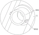
Preferably, the cooling mechanism comprises first mounting grooves, the first mounting grooves are formed in the outer sides of the lower die and the upper die respectively, a plurality of first conveying pipes are mounted inside each first mounting groove, second conveying pipes are arranged in the middle of the two sides of each first mounting groove, and each second conveying pipe is connected with the corresponding first conveying pipe.
As preferred, be located the bed die the T-shaped draw-in groove has all been seted up to the inner wall both sides of second conveyer pipe, be located every of last mould spacing sleeve pipe, every are all installed to the lower surface of second conveyer pipe T-shaped fixture block is all installed to spacing sheathed tube surface both sides, the upper surface one side fixed mounting of installation base has the water pump, the output setting of water pump is in the one side of lieing in the inside one of them second conveyer pipe of bed die, the input setting of water pump is in the inside of liquid reserve tank, liquid reserve tank fixed mounting is in upper surface one side of installation base.
Preferably, ejection mechanism is including the ejector pin, ejector pin evenly distributed alternates and sets up in the bottom of installation base, the bottom fixed mounting of ejector pin has spacing bottom plate, every supplementary kicking block is all installed at the top of ejector pin, every supplementary kicking block all sets up on the bottom inner wall of bed die, all install spacing spring between the upper surface of spacing bottom plate and the lower surface of installation base and on being located the shaft of every ejector pin.
Preferably, sliding plates are installed on two sides of the outer surface of the limiting bottom plate, two sides of each sliding plate are arranged inside the corresponding limiting plate in a sliding mode, each limiting plate is fixedly installed between the bottom of the mounting frame and the lower surface of the mounting base, a limiting sliding groove is formed in one side surface of each limiting plate, limiting sliding blocks are installed on two side surfaces of each sliding plate, and each limiting sliding block is arranged inside the corresponding limiting sliding groove in a sliding mode.
Preferably, an adjusting rack is arranged on one side surface of one of the sliding plates, a connecting plate is mounted on one side surface of each of the two limiting plates close to the adjusting rack, a second driving motor is fixedly mounted on one side surface of one of the connecting plates, an adjusting gear is arranged at an output end of the second driving motor, the other end of the adjusting gear is rotatably arranged on one side surface of the other connecting plate, and the adjusting gear and the adjusting rack are meshed with each other.
Preferably, the driving mechanism comprises an installation box, the installation box is fixedly installed on the upper surface of the transverse plate, a fixed frame is fixedly installed on one side of the upper surface of the installation box, and a fixed plate is installed on one side, close to the fixed frame, of the upper surface of the installation box.
Preferably, a first driving motor is installed on the surface of one side of the fixing plate, a worm is installed at the output end of the first driving motor, the other end of the worm is rotatably arranged on one side of the bottom of the fixing frame, a worm wheel is rotatably installed on one side inside the fixing frame, and the worm wheel are meshed with each other.
Preferably, the two sides in the mounting box are rotatably provided with driving wheels, the bottom of each worm wheel penetrates through the upper side of the mounting box, the end part of each worm wheel is fixedly arranged at the top of one of the driving wheels, a driving belt is arranged on the outer sides of the two driving wheels, and the bottom of each driving wheel is arranged at the end part of one end, located above the transverse plate, of the corresponding rotating screw rod.
Compared with the prior art, the invention has the following beneficial effects:
1. go up the mould and moving the in-process down, under spacing chucking effect between T shape fixture block and T shape draw-in groove, can be linked together the inside first conveyer pipe of mould and the inside first conveyer pipe of bed die, can be inside the coolant liquid in the liquid reserve tank passes through the second conveyer pipe and carries to the first conveyer pipe of different positions through the water pump, thereby can carry out cooling to the inner wall of bed die and last mould, can accomplish the quick cooling work to injection moulding back product through the first conveyer pipe of multiunit, the cooling time is shorter, can effectively improve machining efficiency.
2. Through the meshing transmission between the worm wheel and the worm, under the transmission of the transmission belt, two rotating screw rods can synchronously rotate, so that the height adjustment of the whole upper die is completed, the adjustment precision is higher, the position control of the upper die can be more accurate, the moving process is more stable, the upper die can play a limiting role in the moving process through the matching between the four support rods, the mounting block and the movable mounting sleeve, the upper die can not generate position deviation in the moving process, the injection molding work is more convenient, the injection molding effect is better, the adjusting gear is driven to rotate by the second driving motor, under the meshing transmission between the adjusting gear and the adjusting rack, the adjusting rack can drive the sliding plate on one side to move, so that the limiting bottom plate drives each ejector rod to move upwards, and the molded product can be ejected through the auxiliary ejector block arranged on the inner wall at the bottom of the lower die at the top of the ejector rod, can accomplish the quick drawing of patterns to the shaping back product, the simple operation can effectively improve the efficiency of moulding plastics, through setting up the spacing spring on ejector pin pole body, can remove the in-process at the ejector pin and play the cushioning effect, can make the removal of ejector pin more stable, more conveniently carries out the ejecting work of shaping back product.
Drawings
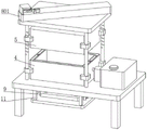
FIG. 1 is a schematic view of the overall structure of a precision injection mold for rapid injection molding according to the present invention;
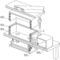
FIG. 2 is a schematic view of another angle of the precision injection mold for rapid injection molding according to the present invention;
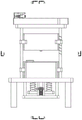
FIG. 3 is a side view of a precision injection mold for rapid injection molding according to the present invention;
FIG. 4 is a schematic cross-sectional view taken along line A-A of FIG. 2 of a precision injection mold for rapid injection molding according to the present invention;
FIG. 5 is a schematic cross-sectional view taken along line B-B of FIG. 2 of a precision injection mold for rapid injection molding according to the present invention;
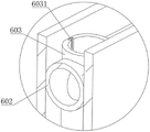
FIG. 6 is an enlarged view of E in FIG. 4 of a precision injection mold for rapid injection molding according to the present invention;
FIG. 7 is an enlarged view of the precision injection mold for rapid injection molding of the present invention at F in FIG. 5;
FIG. 8 is a schematic cross-sectional view taken along line C-C of FIG. 2 of a precision injection mold for rapid injection molding according to the present invention;
FIG. 9 is a schematic diagram of a detailed structure of an ejection mechanism of a precision injection mold for rapid injection molding according to the present invention;
FIG. 10 is an enlarged view of the precise injection mold for rapid injection molding of the present invention at G in FIG. 8;
FIG. 11 is an enlarged view of the precision injection mold for rapid injection molding of the present invention at D in FIG. 1;
FIG. 12 is a schematic view of the internal structure of the mounting case of the precision injection mold for rapid injection molding according to the present invention.
In the figure: 1. installing a base; 2. a support bar; 3. mounting blocks; 4. a lower die; 5. an upper die; 6. a cooling mechanism; 601. a first mounting groove; 602. a first delivery pipe; 603. a second delivery pipe; 6031. a T-shaped clamping groove; 604. a limiting sleeve; 6041. a T-shaped fixture block; 605. a water pump; 606. a liquid storage tank; 7. a transverse plate; 8. a drive mechanism; 801. installing a box; 802. a fixed mount; 803. a fixing plate; 804. a first drive motor; 805. a worm; 806. a worm gear; 807. a driving wheel; 808. a drive belt; 9. an ejection mechanism; 901. a top rod; 9011. an auxiliary top block; 902. a limiting bottom plate; 9021. a limiting spring; 903. a sliding plate; 9031. a limiting slide block; 9032. adjusting the rack; 904. a limiting plate; 9041. a limiting chute; 9042. a connecting plate; 9043. a second drive motor; 9044. an adjusting gear; 10. rotating the screw rod; 11. a mounting frame; 12. injecting a pipe orifice; 13. a movable mounting sleeve.
Detailed Description
The technical solutions in the embodiments of the present invention will be clearly and completely described below with reference to the embodiments of the present invention, and it is obvious that the described embodiments are only a part of the embodiments of the present invention, and not all of the embodiments. All other embodiments, which can be derived by a person skilled in the art from the embodiments given herein without making any creative effort, shall fall within the protection scope of the present invention.
Examples
As shown in fig. 1-12, a precision injection mold for rapid injection molding comprises a mounting base 1, four support rods 2 are uniformly and fixedly arranged on one side of the upper surface of the mounting base 1, a transverse plate 7 is fixedly arranged on the top of each support rod 2, a lower mold 4 is arranged on one side of the upper surface of the mounting base 1, a mounting block 3 for limiting the lower mold 4 is fixed on the bottom rod body of each support rod 2, an upper mold 5 is movably arranged below the transverse plate 7, a movable mounting sleeve 13 for movably mounting the upper mold 5 is movably arranged on the upper rod body of each support rod 2, a driving mechanism 8 for driving the upper mold 5 to move is arranged on the upper surface of the transverse plate 7, a cooling mechanism 6 for cooling a molded product is arranged on one side of the mounting base 1, an ejection mechanism 9 for ejecting the molded product is arranged on the lower surface of the mounting base 1, one side of the lower die 4 is provided with an injection molding pipe orifice 12, and the lower surface of the mounting base 1 is provided with a mounting frame 11.
In this embodiment, wherein the upper side pole body of two bracing pieces 2 that the diagonal set up installs rotation lead screw 10, be screw-thread fit between movable mounting cover 13 that is located on rotation lead screw 10 and the rotation lead screw 10, diaphragm 7 is all run through at the top of every rotation lead screw 10, through the screw-thread fit between rotation lead screw 10 and the corresponding position movable mounting cover 13, the rotation that makes rotation lead screw 10 can drive whole upper mold 5 and remove, thereby accomplish the cooperation between upper mold 5 and the lower mold 4, conveniently carry out the work of moulding plastics.
In this embodiment, the cooling mechanism 6 includes a first mounting groove 601, the first mounting groove 601 is respectively disposed at the outer sides of the lower mold 4 and the upper mold 5, each first mounting groove 601 is internally provided with a plurality of first delivery pipes 602, the middle portions of both sides of each first mounting groove 601 are provided with second delivery pipes 603, each second delivery pipe 603 is connected with the corresponding first delivery pipe 602, both sides of the inner wall of the second delivery pipe 603 in the lower mold 4 are provided with T-shaped clamping grooves 6031, the lower surface of each second delivery pipe 603 in the upper mold 5 is provided with a position-limiting sleeve 604, both sides of the outer surface of each position-limiting sleeve 604 are provided with T-shaped clamping blocks 6041, one side of the upper surface of the mounting base 1 is fixedly provided with a water pump 605, the output end of the water pump 605 is disposed at one side of one of the second delivery pipes 603 in the lower mold 4, the input end of the water pump 605 is disposed in the liquid storage tank 606, liquid reserve tank 606 fixed mounting can be carried the inside of the inside first conveyer pipe 602 of first mounting groove 601 in supreme mould 5 and the bed die 4 with the coolant liquid in the liquid reserve tank 606 in upper surface one side of installation base 1 through water pump 605 to can carry out quick cooling work to the product after the shaping in cope die 5 and the bed die 4, cooling time is shorter, can effectively improve machining efficiency.
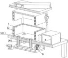
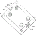
In this embodiment, the ejection mechanism 9 includes ejector rods 901, the ejector rods 901 are uniformly distributed and inserted in the bottom of the mounting base 1, a limiting bottom plate 902 is fixedly mounted at the bottom of the ejector rods 901, an auxiliary ejector block 9011 is mounted at the top of each ejector rod 901, each auxiliary ejector block 9011 is disposed on the inner wall of the bottom of the lower mold 4, a limiting spring 9021 is mounted between the upper surface of the limiting bottom plate 902 and the lower surface of the mounting base 1 and on the rod body of each ejector rod 901, sliding plates 903 are mounted on two sides of the outer surface of the limiting bottom plate 902, two sides of each sliding plate 903 are slidably disposed inside the limiting plate 904, each limiting plate 904 is fixedly mounted between the bottom of the mounting frame 11 and the lower surface of the mounting base 1, a limiting chute 9041 is disposed on one side surface of each limiting plate 904, a limiting slider 9031 is mounted on two side surfaces of each sliding plate 903, each limiting slider 9031 is slidably disposed inside the limiting chute 41 at a corresponding position, an adjusting rack 9032 is arranged on one side surface of one of the sliding plates 903, connecting plates 9042 are mounted on one side surfaces of two limiting plates 904 close to the adjusting rack 9032, a second driving motor 9043 is fixedly mounted on one side surface of one of the connecting plates 9042, an adjusting gear 9044 is arranged at an output end of the second driving motor 9043, the other end of the adjusting gear 9044 is rotatably arranged on one side surface of the other connecting plate 9042, the adjusting gear 9044 and the adjusting rack 9032 are mutually engaged, the moving process of the limiting bottom plate 902 can be more stable through sliding fit between limiting sliding blocks 9031 which are slidably arranged in the limiting sliding grooves 9041, ejection work of a product after ejection molding can be more conveniently performed by the ejector rods 901, and a buffer effect can be achieved in the moving process of the ejector rods 901 under the elastic action of limiting springs 9021 which are arranged between the limiting bottom plate 902 and the lower surface of the mounting base 1, the movement of the top auxiliary top block 9011 can be more stable.
In this embodiment, the driving mechanism 8 includes an installation box 801, the installation box 801 is fixedly installed on the upper surface of the horizontal plate 7, a fixing frame 802 is fixedly installed on one side of the upper surface of the installation box 801, a fixing plate 803 is installed on one side of the upper surface of the installation box 801 close to the fixing frame 802, a first driving motor 804 is installed on one side surface of the fixing plate 803, a worm 805 is installed at an output end of the first driving motor 804, the other end of the worm 805 is rotatably disposed on one side of the bottom of the fixing frame 802, a worm wheel 806 is rotatably installed on one side inside the fixing frame 802, the worm 805 and the worm wheel 806 are engaged with each other, driving wheels 807 are rotatably installed on both sides inside the installation box 801, the bottom of the worm wheel 806 penetrates through the upper side of the installation box 801, and the end portion of the worm wheel 807 is fixedly installed on the top portion of one of the driving wheels, a driving belt 808 is installed on the outer side of two driving wheels 807, the bottom portion of each driving wheel is installed on the end portion of the rotating screw 10 located above the horizontal plate 7, through the meshing transmission between worm wheel 806 and the worm 805, can make the rotation precision of rotating lead screw 10 higher, it is more accurate to its position control to the altitude mixture control that makes last mould 5 is more accurate, and the position cooperation is more accurate between messenger's last mould 5 and the bed die 4.
The working principle of the rapid injection molding precision injection mold is as follows:
when in use, the upper die 5 is driven to move downwards by the driving mechanism 8, so that the upper die 5 is matched with the lower die 4, in the driving process, the worm 805 is driven to rotate by the first driving motor 804, under the meshing transmission between the worm 805 and the worm wheel 806, the worm wheel 806 can drive one of the transmission wheels 807 in the installation box 801 to rotate, under the transmission of the transmission belt 808, the two rotating screw rods 10 can synchronously rotate, under the matching of the threads between the rotating screw rods 10 and the movable installation sleeves 13 on the rod bodies thereof, the movable installation sleeves 13 can drive the whole upper die 5 to move downwards, so that the upper die 5 is matched with the lower die 4, the injection molding work can be carried out on the interior of the die through the injection molding pipe orifice 12, the height adjustment of the whole upper die 5 can be completed through the meshing transmission between the worm wheel 806 and the worm wheel 805, the adjustment precision is higher, the position control of the upper die 5 can be more precise, the moving process is more stable, the upper die 5 can play a limiting role in the moving process through the matching between the four support rods 2, the mounting block 3 and the movable mounting sleeve 13, so that the upper die 5 cannot generate position deviation in the moving process, the injection molding work is more convenient, the injection molding effect is better, the upper die 5 can be clamped in a limiting way between the T-shaped clamping block 6041 and the T-shaped clamping groove 6031 in the moving process, the limiting sleeve 604 at the bottom of the second conveying pipe 603 in the upper die 5 can be matched with the second conveying pipe 603 in the lower die 4, so that the first conveying pipe 602 in the upper die 5 can be communicated with the first conveying pipe 602 in the lower die 4, after the injection molding is finished, the cooling liquid in the liquid storage tank 606 can be conveyed into the first conveying pipe 602 at different positions through the second conveying pipe 603 through the water pump 605, and the inner walls of the lower die 4 and the upper die 5 can be cooled, the fast cooling work of the injection molded product can be completed through a plurality of groups of first conveying pipes 602, the cooling time is shorter, the processing efficiency can be effectively improved, after the cooling is completed, the product can be ejected through the ejection mechanism 9, the adjusting gear 9044 is driven to rotate through the second driving motor 9043, the adjusting rack 9032 can drive the sliding plate 903 on one side to move under the meshing transmission between the adjusting gear 9044 and the adjusting rack 9032, so that the limiting bottom plate 902 drives each ejector rod 901 to move upwards, the molded product can be ejected through the auxiliary ejector block 9011 arranged on the inner wall of the bottom of the lower mold 4 at the top of the ejector rod 901, the fast demolding of the molded product can be completed, the operation is convenient and fast, the injection molding efficiency can be effectively improved, the limiting spring 9021 arranged on the body of the ejector rod 901 can play a role in buffering role in the moving process of the ejector rod 901, and the movement of the ejector rod 901 can be more stable, the ejection work of the formed product is more convenient.
It should be understood that the above-mentioned embodiments of the present invention are only examples for clearly illustrating the present invention, and are not intended to limit the embodiments of the present invention, and it will be obvious to those skilled in the art that other variations and modifications can be made on the basis of the above description, and all embodiments cannot be exhaustive, and obvious variations and modifications may be made within the scope of the present invention.
Claims (10)
1. The utility model provides a precision injection mold who moulds plastics fast, includes installation base (1), its characterized in that: four supporting rods (2) are uniformly and fixedly arranged on one side of the upper surface of the mounting base (1), a transverse plate (7) is fixedly arranged at the top of each supporting rod (2), a lower die (4) is arranged on one side of the upper surface of the mounting base (1), a mounting block (3) for limiting the lower die (4) is fixed on each bottom rod body of each supporting rod (2), an upper die (5) is movably arranged below the transverse plate (7), a movable mounting sleeve (13) for movably mounting the upper die (5) is movably mounted on each upper rod body of each supporting rod (2), a driving mechanism (8) for driving the upper die (5) to move is arranged on the upper surface of the transverse plate (7), a cooling mechanism (6) for cooling a formed product is arranged on one side of the mounting base (1), the lower surface of the installation base (1) is provided with an ejection mechanism (9) used for ejecting a formed product, one side of the lower die (4) is provided with an injection molding pipe orifice (12), and the lower surface of the installation base (1) is provided with an installation frame (11).
2. The precision injection mold for rapid injection molding according to claim 1, wherein: the upper side rods of the two support rods (2) which are arranged diagonally are provided with rotary screw rods (10), the movable mounting sleeves (13) which are positioned on the rotary screw rods (10) are in threaded fit with the rotary screw rods (10), and the top of each rotary screw rod (10) penetrates through the transverse plate (7).
3. The precision injection mold for rapid injection molding according to claim 1, wherein: cooling body (6) are including first mounting groove (601), the outside at bed die (4) and last mould (5) is seted up respectively in first mounting groove (601) every first conveyer pipe (602), every are all installed to first mounting groove (601) inside the both sides middle part of first mounting groove (601) all is provided with second conveyer pipe (603), every second conveyer pipe (603) all are connected with the first conveyer pipe (602) that correspond the position.
4. The precision injection mold for rapid injection molding according to claim 3, wherein: be located in bed die (4) T shape draw-in groove (6031) have all been seted up to the inner wall both sides of second conveyer pipe (603), are located every in last mould (5) spacing sleeve pipe (604) are all installed to the lower surface of second conveyer pipe (603), every T shape fixture block (6041) are all installed to the surface both sides of spacing sleeve pipe (604), upper surface one side fixed mounting of installation base (1) has water pump (605), the output setting of water pump (605) is in the one side of lieing in inside one of them second conveyer pipe (603) of bed die (4), the input setting of water pump (605) is in the inside of liquid reserve tank (606), liquid reserve tank (606) fixed mounting is in upper surface one side of installation base (1).
5. The precision injection mold for rapid injection molding according to claim 1, wherein: the ejection mechanism (9) comprises ejector rods (901), the ejector rods (901) are uniformly distributed and penetrate through the bottom of the mounting base (1), a limiting bottom plate (902) is fixedly mounted at the bottom of the ejector rods (901), an auxiliary ejector block (9011) is mounted at the top of each ejector rod (901), each auxiliary ejector block (9011) is arranged on the inner wall of the bottom of the lower die (4), and a limiting spring (9021) is mounted between the upper surface of the limiting bottom plate (902) and the lower surface of the mounting base (1) and located on the rod body of each ejector rod (901).
6. The precision injection mold for rapid injection molding according to claim 5, wherein: sliding plates (903) are installed on two sides of the outer surface of the limiting bottom plate (902), two sides of each sliding plate (903) are arranged inside the corresponding limiting plate (904) in a sliding mode, each limiting plate (904) is fixedly installed between the bottom of the mounting frame (11) and the lower surface of the mounting base (1), a limiting sliding groove (9041) is formed in one side surface of each limiting plate (904), a limiting sliding block (9031) is installed on the surfaces of two sides of each sliding plate (903), and each limiting sliding block (9031) is arranged inside the corresponding limiting sliding groove (9041) in a sliding mode.
7. The precision injection mold for rapid injection molding according to claim 6, wherein: an adjusting rack (9032) is arranged on one side surface of one of the sliding plates (903), connecting plates (9042) are mounted on one side surfaces of the two limiting plates (904) close to the adjusting rack (9032), a second driving motor (9043) is fixedly mounted on one side surface of one of the connecting plates (9042), an adjusting gear (9044) is arranged at the output end of the second driving motor (9043), the other end of the adjusting gear (9044) is rotatably arranged on one side surface of the other connecting plate (9042), and the adjusting gear (9044) and the adjusting rack (9032) are meshed with each other.
8. The precision injection mold for rapid injection molding according to claim 1, wherein: actuating mechanism (8) are including install bin (801), install bin (801) fixed mounting is at the upper surface of diaphragm (7), the upper surface one side fixed mounting of install bin (801) has mount (802), one side that install bin (801) upper surface is close to mount (802) installs fixed plate (803).
9. The precision injection mold for rapid injection molding according to claim 8, wherein: one side surface mounting of fixed plate (803) has first driving motor (804), worm (805) are installed to the output of first driving motor (804), the other end of worm (805) is rotated and is set up in bottom one side of mount (802), inside one side of mount (802) is rotated and is installed worm wheel (806), intermeshing between worm (805) and worm wheel (806).
10. The precision injection mold for rapid injection molding according to claim 9, wherein: all rotate the inside both sides of install bin (801) and install drive wheel (807), the upside and the tip fixed mounting that install bin (801) are run through to the bottom of worm wheel (806) are in one of them the top of drive wheel (807), two drive belt (808) are installed to the outside of drive wheel (807), every the bottom of drive wheel (807) all install the rotation lead screw (10) that corresponds the position and be located the one end tip of diaphragm (7) top.
Priority Applications (1)
| Application Number | Priority Date | Filing Date | Title |
|---|---|---|---|
| CN202210594220.6A CN114872280A (en) | 2022-05-27 | 2022-05-27 | Precision injection mold capable of achieving rapid injection molding |
Applications Claiming Priority (1)
| Application Number | Priority Date | Filing Date | Title |
|---|---|---|---|
| CN202210594220.6A CN114872280A (en) | 2022-05-27 | 2022-05-27 | Precision injection mold capable of achieving rapid injection molding |
Publications (1)
| Publication Number | Publication Date |
|---|---|
| CN114872280A true CN114872280A (en) | 2022-08-09 |
Family
ID=82679120
Family Applications (1)
| Application Number | Title | Priority Date | Filing Date |
|---|---|---|---|
| CN202210594220.6A Pending CN114872280A (en) | 2022-05-27 | 2022-05-27 | Precision injection mold capable of achieving rapid injection molding |
Country Status (1)
| Country | Link |
|---|---|
| CN (1) | CN114872280A (en) |
Cited By (3)
| Publication number | Priority date | Publication date | Assignee | Title |
|---|---|---|---|---|
| CN116001184A (en) * | 2022-12-12 | 2023-04-25 | 合肥大道模具有限责任公司 | Rotational molding equipment for machining POM hand mold |
| CN116922668A (en) * | 2023-09-19 | 2023-10-24 | 成都易联智通信息技术有限公司 | Injection mold for producing data acquisition device shell |
| CN117140862A (en) * | 2023-10-30 | 2023-12-01 | 安徽安大中鼎橡胶技术开发有限公司 | Mold for solving molding warpage of rubber/carbon nano tube composite material special-shaped piece |
Citations (8)
| Publication number | Priority date | Publication date | Assignee | Title |
|---|---|---|---|---|
| CN107471550A (en) * | 2017-10-11 | 2017-12-15 | 苏州乔布注塑工业有限公司 | A kind of plastic mould with cooling structure |
| CN107775911A (en) * | 2017-10-31 | 2018-03-09 | 瑞元(天津)电子有限公司 | A kind of Novel injection mold |
| CN108284566A (en) * | 2017-12-28 | 2018-07-17 | 太仓朗盛金属制品有限公司 | A kind of mold and its working method shortening working hour |
| CN210126258U (en) * | 2019-05-27 | 2020-03-06 | 曾秀琴 | Novel demoulding device for processing injection mould |
| CN210999776U (en) * | 2019-10-11 | 2020-07-14 | 上海卓祎模塑科技有限公司 | Injection mold with buffer function |
| CN211307268U (en) * | 2019-10-24 | 2020-08-21 | 广西贵港雅达科技有限公司 | Injection mold convenient to stable drawing of patterns |
| CN214188130U (en) * | 2021-01-14 | 2021-09-14 | 东莞市誉嘉塑料模具有限公司 | But fashioned cell-phone panel injection mold of highlight |
| CN113681781A (en) * | 2021-08-26 | 2021-11-23 | 泰州市政锋注塑有限公司 | Cooling unit for plastic support die |
-
2022
- 2022-05-27 CN CN202210594220.6A patent/CN114872280A/en active Pending
Patent Citations (8)
| Publication number | Priority date | Publication date | Assignee | Title |
|---|---|---|---|---|
| CN107471550A (en) * | 2017-10-11 | 2017-12-15 | 苏州乔布注塑工业有限公司 | A kind of plastic mould with cooling structure |
| CN107775911A (en) * | 2017-10-31 | 2018-03-09 | 瑞元(天津)电子有限公司 | A kind of Novel injection mold |
| CN108284566A (en) * | 2017-12-28 | 2018-07-17 | 太仓朗盛金属制品有限公司 | A kind of mold and its working method shortening working hour |
| CN210126258U (en) * | 2019-05-27 | 2020-03-06 | 曾秀琴 | Novel demoulding device for processing injection mould |
| CN210999776U (en) * | 2019-10-11 | 2020-07-14 | 上海卓祎模塑科技有限公司 | Injection mold with buffer function |
| CN211307268U (en) * | 2019-10-24 | 2020-08-21 | 广西贵港雅达科技有限公司 | Injection mold convenient to stable drawing of patterns |
| CN214188130U (en) * | 2021-01-14 | 2021-09-14 | 东莞市誉嘉塑料模具有限公司 | But fashioned cell-phone panel injection mold of highlight |
| CN113681781A (en) * | 2021-08-26 | 2021-11-23 | 泰州市政锋注塑有限公司 | Cooling unit for plastic support die |
Non-Patent Citations (1)
| Title |
|---|
| 陈万林: "《实用塑料注塑模设计与制造》", 机械工业出版社, pages: 120 - 121 * |
Cited By (4)
| Publication number | Priority date | Publication date | Assignee | Title |
|---|---|---|---|---|
| CN116001184A (en) * | 2022-12-12 | 2023-04-25 | 合肥大道模具有限责任公司 | Rotational molding equipment for machining POM hand mold |
| CN116001184B (en) * | 2022-12-12 | 2023-12-26 | 合肥大道模具有限责任公司 | Rotational molding equipment for machining POM hand mold |
| CN116922668A (en) * | 2023-09-19 | 2023-10-24 | 成都易联智通信息技术有限公司 | Injection mold for producing data acquisition device shell |
| CN117140862A (en) * | 2023-10-30 | 2023-12-01 | 安徽安大中鼎橡胶技术开发有限公司 | Mold for solving molding warpage of rubber/carbon nano tube composite material special-shaped piece |
Similar Documents
| Publication | Publication Date | Title |
|---|---|---|
| CN114872280A (en) | Precision injection mold capable of achieving rapid injection molding | |
| CN110962302B (en) | Injection molding equipment of PP plastic spring | |
| CN210390015U (en) | Mould tray with height adjusting function | |
| CN115056441A (en) | Injection molding equipment with from convertible demoulding mechanism | |
| CN111531794A (en) | Plastic tray machining and forming device and operation method thereof | |
| CN112757579A (en) | Injection mold is used in auto-parts production and processing | |
| CN113172826B (en) | Integrated injection mold | |
| CN208148388U (en) | A kind of internal screw thread rotation depanning mold | |
| CN213166606U (en) | Demoulding mechanism for plastic injection mould | |
| CN211054253U (en) | Multi-axis numerical control machining die | |
| CN205021935U (en) | Injection molding machine carousel formula locking mechanism | |
| CN208375900U (en) | A kind of breakage-proof stripper apparatus of plastic mould | |
| CN113071077A (en) | Round rack rail type I-shaped workpiece injection mold device | |
| CN210308728U (en) | Automatic feeding device of continuous die | |
| CN217021320U (en) | Ejection device for mold processing | |
| CN218139680U (en) | Injection molding machine is used in processing of accurate plastic part convenient to ejection of compact | |
| CN218256456U (en) | Pipe orifice clamping groove forming mechanism of plastic pipe mold | |
| CN219133149U (en) | High-precision plug-in injection mold | |
| CN213919177U (en) | Rapid prototyping's accurate plastic mould | |
| CN219968636U (en) | Insert row plastic housing device of moulding plastics | |
| CN215151326U (en) | Full-automatic demoulding precision plastic mould for motor worm | |
| CN220576469U (en) | Through-flow injection molding plastic part integrated forming equipment | |
| CN219522890U (en) | Injection mold for automobile front lampshade | |
| CN219095731U (en) | Plastic product rapid prototyping processing equipment convenient to clearance | |
| CN219564021U (en) | Injection mold of plastic part |
Legal Events
| Date | Code | Title | Description |
|---|---|---|---|
| PB01 | Publication | ||
| PB01 | Publication | ||
| SE01 | Entry into force of request for substantive examination | ||
| SE01 | Entry into force of request for substantive examination | ||
| RJ01 | Rejection of invention patent application after publication |
Application publication date: 20220809 |
|
| RJ01 | Rejection of invention patent application after publication |