Paper punching die
Technical Field
The invention relates to the technical field of paper punching dies, in particular to a paper punching die.
Background
The paper punching die is a paper product cold punching die for punching holes by utilizing modes of air pressure, electric, manual and the like. It is widely used for: the paper punching die can be used for punching paper made of materials such as computer printing paper, elevator paper, printing paper, white board paper, coated paper and offset paper.
The existing paper punching die is simple in structure and single in function, when paper is punched, the paper cannot be well fixed, when more paper is punched, because more paper is stacked together to have a certain thickness, when the paper is stressed unevenly, the paper is easy to shift, and further the punched hole position is inclined, so that the punching is unqualified, when a punching knife punches the paper, the part of the paper, which is contacted with the punching knife, is bound to be pressed and deformed, and the peripheral paper part of the punching knife can be tilted upwards, so that the quality of the hole formed on the paper is low, and the punching quality is influenced, in addition, when the paper is punched, if the surface of the paper is wrinkled, and the paper is not completely flattened, when the paper is punched, the punching precision of the punching die on the paper can be influenced, and small paper sheets punched after a plurality of punching times can block a punch head, inconvenient clearance still influences subsequent quality of punching.
Disclosure of Invention
Aiming at the problems in the prior art, the invention provides a paper punching die. The invention discloses a paper punching die, which aims to solve the problems that when a large number of papers are punched, the papers are easy to deviate so that the punched hole positions are inclined, folds are formed on the surfaces of the papers, the precision of punching on the papers is influenced due to the fact that the papers are not completely flattened, small paper sheets punched after punching for multiple times block a punch head, cleaning is inconvenient, the subsequent punching quality is influenced and the like.
The technical scheme adopted by the invention for solving the technical problems is as follows: a paper punching die comprises a lower die plate, an upper die plate and a top plate, wherein a workbench is fixedly arranged in the middle of the top end of the lower die plate, a through hole is formed in the middle of the top end of the workbench, guide posts are fixedly arranged on two sides of the top end of the lower die plate, the top end of each guide post is fixedly provided with the top plate, a cylinder is fixedly arranged in the middle of the top end of the top plate, a telescopic rod is slidably arranged at the bottom end of the cylinder, the outer sides of the two guide posts are fixedly sleeved with the same upper die plate, the middle of the top end of the upper die plate is fixedly connected with the bottom end of the telescopic rod, matching rods are fixedly arranged on two sides of the bottom of the upper die plate, mounting blocks are fixedly arranged on two sides of the bottom of the upper die plate, first rotating rods are rotatably arranged at the bottoms of the two mounting blocks, connecting rods are sleeved on the outer sides of the middle of the two first rotating rods, and return springs are sleeved on the outer sides of two ends of the two first rotating rods, just return spring's one end and first dwang fixed connection, return spring's the other end and connecting rod fixed connection, two it is equipped with same second dwang to rotate between the bottom of connecting rod, the outside cover of second dwang is equipped with the flattening roller.
Preferably, the opposite side at connecting rod openly top has seted up the spout, the inside slip of spout is equipped with the slider, the front of slider is rotated and is connected with the dead lever, the both sides on dead lever top are all fixed and are provided with first fixture block.
Preferably, a clamping groove is formed in one side of the bottom end of the upper template, a movable groove is formed in one side of the top end of the upper template, the movable groove is fixedly communicated with the clamping groove, a first movable rod is movably arranged in the movable groove, a second clamping block is fixedly arranged at the other end of the first movable rod, the second clamping block is matched with the first clamping block, and a second reset spring is fixedly arranged on one side of the bottom of the movable groove.
Preferably, the fixed mount that is provided with in top in activity groove, the middle activity on mount top is equipped with the second movable rod, the outside cover at second movable rod top is equipped with third reset spring, the bottom mounting of second movable rod is provided with the cooperation piece, just the one end phase-match of cooperation piece and first movable rod.
Preferably, the both sides of cope match-plate pattern bottom all are fixed and are provided with the fixed plate, two one side of fixed plate bottom all is fixed and is provided with first reset spring, just first reset spring's one end and connecting rod fixed connection.
Preferably, the both sides on lower bolster back top are all movable and are equipped with first piston rod, the outside cover of first piston rod is equipped with first spring, the bottom mounting of first piston rod is provided with first piston, first piston chamber has been seted up in the outside of first piston, second piston chamber has been seted up to positive one side of first piston chamber, just second piston chamber passes through the fixed intercommunication of breather pipe and first piston chamber, the inside slip of second piston chamber is equipped with the second piston, the fixed second piston rod that is provided with in the centre on second piston top, the outside cover of second piston rod bottom is equipped with the second spring.
Preferably, the mounting plates are fixedly arranged on two sides of the top end of the back of the lower template, the clamping blocks are rotatably arranged at the tops of the mounting plates, the third spring is fixedly arranged on the other side of the bottom of the mounting plate, and the top end of the third spring is fixedly connected with the bottom ends of the clamping blocks.
Preferably, the fixed mounting bracket that is provided with in centre of cope match-plate pattern bottom, the fixed installation sleeve that is provided with in centre of mounting bracket bottom, the fixed fixing bolt that is provided with in one side at installation sleeve top, the telescopic inside cover of installation is equipped with the sword of punching, the opening has been seted up in the centre on mounting bracket top, the inside cover of opening is equipped with the guide arm, the outside cover at guide arm top is equipped with the fourth spring, just the guide arm passes the inside of the sword of punching.
The invention has the beneficial effects that:
(1) the invention relates to a paper punching die, which adopts an installation block, a connecting rod, a return spring, a flattening roller, a first return spring, a fixed rod, a first clamping block, a second clamping block, a first movable rod and a second movable rod, wherein the first rotary rod is arranged at the bottom of the installation block in a rotating manner, so that the connecting rod can rotate around the first rotary rod, the same flattening roller is arranged at the bottom of the connecting rod in a rotating manner, the flattening roller can be driven to roll on a workbench through downward movement of an upper die plate, the paper on the workbench can be pressed tightly by the flattening roller through the return spring, so that the paper is flattened, the problem that the precision of punching is influenced by wrinkles on the surface of the paper is solved, and meanwhile, when the upper die plate continuously moves downward, the fixed rod can be driven to enter a clamping groove, so that the first clamping block is clamped with the second clamping block, so that the connecting rod can be fixed, avoid when the flattening roller return that rises at the cope match-plate pattern, it removes to drive the paper, thereby make the paper take place the displacement, influence the paper and punch, in addition, after the completion is punched to the paper, when the cope match-plate pattern rises to certain position, the second movable rod that the activity was equipped with in the middle of the mount contacts with the bottom of roof, thereby make the second movable rod remove downwards, and then promote first movable rod through the cooperation piece and remove to both sides, thereby make second fixture block and first fixture block separation, reset the flattening roller through fixed plate and first reset spring simultaneously.
(2) The invention relates to a paper punching die, which adopts a matching rod, a first piston rod, a second piston rod, a first piston chamber, a second piston chamber, a mounting plate and a clamping block, wherein the matching rod is fixedly arranged on two sides of the bottom of an upper template, when the upper template moves downwards, the matching rod is also driven to move, the first piston rod is further compressed through the matching rod, the first piston rod is further driven to compress air in the first piston chamber through the first piston, so that a second piston in the second piston chamber can be driven to move upwards, the second piston rod is driven to move through the second piston, in addition, the first piston rod and the second piston rod can be reset through the first spring and the second spring, the clamping block rotatably arranged on the top of the mounting plate is propped through the second piston rod, and paper can be clamped through the clamping block, the problem that when more paper is punched, the paper is easy to shift due to the fact that the paper is stacked together to have a certain thickness when the paper is stressed unevenly, and then the punched hole position is inclined, so that punching is unqualified is avoided.
(3) The paper punching die provided by the invention adopts the mounting frame, the mounting sleeve, the through hole, the guide rod, the fourth spring, the punching knife and the fixing bolt, the mounting frame is fixedly arranged in the middle of the bottom end of the upper die plate, the mounting sleeve and the fixing bolt are fixedly arranged in the middle of the bottom end of the mounting frame, the punching knife can be fixedly mounted, the through hole is formed in the middle of the top end of the mounting frame, the guide rod is sleeved in the through hole, the fourth spring is sleeved on the outer side of the top of the guide rod, the guide rod penetrates through the inside of the punching knife, when the punching knife punches paper, paper scraps in the punching knife can be cleaned through the guide rod, and the situation that the paper scraps in the punching knife are remained and the quality of subsequent punching is influenced is avoided.
Drawings
The invention is further illustrated with reference to the following figures and examples.
FIG. 1 is a schematic view of an overall structure of a paper punching mold according to the present invention;
FIG. 2 is a schematic view of an overall structure of a paper punching mold according to the present invention;
FIG. 3 is a schematic view of a first rotating rod of the paper punching mold according to the present invention;
FIG. 4 is a schematic diagram of a movable slot structure of a paper punching mold according to the present invention;
FIG. 5 is a schematic diagram of a first piston chamber of the paper punching mold according to the present invention;
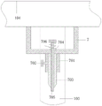
fig. 6 is a schematic structural view of an installation frame of the paper punching die provided by the invention.
In the figure: 1. a lower template; 101. a work table; 102. a through hole; 103. a guide post; 104. mounting a template; 105. a mating rod; 2. mounting blocks; 201. a first rotating lever; 202. a connecting rod; 203. a return spring; 204. a second rotating lever; 205. flattening rollers; 206. a chute; 207. a slider; 208. fixing the rod; 209. a first clamping block; 3. a fixing plate; 301. a first return spring; 4. a movable groove; 401. a clamping groove; 402. a first movable bar; 403. a second fixture block; 404. a second return spring; 405. a fixed mount; 406. a second movable bar; 407. a third return spring; 408. a matching block; 5. a first piston rod; 501. a first spring; 502. a first piston; 503. a first piston chamber; 504. a second piston chamber; 505. a second piston; 506. a second spring; 507. a second piston rod; 6. mounting a plate; 601. a clamping block; 602. a third spring; 7. a mounting frame; 701. installing a sleeve; 702. fixing the bolt; 703. a punching knife; 704. a port; 705. a guide bar; 706. a fourth spring; 8. a top plate; 801. a cylinder; 802. a telescopic rod.
Detailed Description
In order to make the technical means, the creation characteristics, the achievement purposes and the effects of the invention easy to understand, the invention is further described with the specific embodiments.
As shown in FIGS. 1-6, the paper punching die comprises a lower die plate 1, an upper die plate 104 and a top plate 8, wherein a worktable 101 is fixedly arranged in the middle of the top end of the lower die plate 1, a through hole 102 is formed in the middle of the top end of the worktable 101, guide pillars 103 are fixedly arranged on both sides of the top end of the lower die plate 1, the top end of each guide pillar 103 is fixedly provided with the top plate 8, an air cylinder 801 is fixedly arranged in the middle of the top end of the top plate 8, a telescopic rod 802 is slidably arranged at the bottom end of the air cylinder 801, the outer sides of the two guide pillars 103 are fixedly sleeved with the same upper die plate 104, the middle of the top end of the upper die plate 104 is fixedly connected with the bottom end of the telescopic rod 802, matching rods 105 are fixedly arranged on both sides of the bottom of the upper die plate 104, mounting blocks 2 are fixedly arranged on both sides of the bottom of the upper die plate 104, first rotating rods 201 are rotatably arranged at the bottoms of the two mounting blocks 2, and connecting rods 202 are sleeved on the outer sides of the middle of the two first rotating rods 201, the outside at two first dwang 201 both ends all overlaps and is equipped with back-force spring 203, and the one end and the first dwang 201 fixed connection of back-force spring 203, the other end and the connecting rod 202 fixed connection of back-force spring 203, it is equipped with same second dwang 204 to rotate between the bottom of two connecting rods 202, the outside cover of second dwang 204 is equipped with flattening roller 205, through starting cylinder 801, cylinder 801 drives telescopic link 802 and moves down, and then can drive cope match-plate pattern 104 and remove along guide pillar 103, through first dwang 201, can connecting rod 202 rotate around first dwang 201, and can make flattening roller 205 compress tightly the paper on the workstation 101 through back-force spring 203, thereby carry out the flattening to the paper.
Specifically, the sliding groove 206 has been seted up to the opposite side at connecting rod 202 positive top, and the inside slip of sliding groove 206 is equipped with slider 207, and slider 207's positive rotation is connected with dead lever 208, and the both sides on dead lever 208 top all are fixed and are provided with first fixture block 209, and slider 207 can take the sliding groove 206 to slide, and dead lever 208 can rotate on slider 207.
Specifically, a clamping groove 401 is formed in one side of the bottom end of the upper die plate 104, a movable groove 4 is formed in one side of the top end of the upper die plate 104, the movable groove 4 is fixedly communicated with the clamping groove 401, a first movable rod 402 is arranged in the movable groove 4, a second clamping block 403 is fixedly arranged at the other end of the first movable rod 402, the second clamping block 403 is matched with the first clamping block 209, a second reset spring 404 is fixedly arranged on one side of the bottom of the movable groove 4, and the first movable rod 402 can be reset through the second reset spring 404.
Specifically, the fixed mount 405 that is provided with in top of activity groove 4, the middle activity on mount 405 top is equipped with second movable rod 406, the outside cover at second movable rod 406 top is equipped with third reset spring 407, the bottom mounting of second movable rod 406 is provided with cooperation piece 408, and the one end phase-match of cooperation piece 408 and first movable rod 402, can reset second movable rod 406 through third reset spring 407, remove through second movable rod 406 simultaneously, and then can make first movable rod 402 remove.
Specifically, the fixing plates 3 are fixedly arranged on two sides of the bottom end of the upper die plate 104, the first return springs 301 are fixedly arranged on one sides of the bottoms of the two fixing plates 3, and one ends of the first return springs 301 are fixedly connected with the connecting rod 202.
Specifically, two sides of the top end of the back of the lower template 1 are movably provided with a first piston rod 5, the outer side of the first piston rod 5 is sleeved with a first spring 501, the bottom end of the first piston rod 5 is fixedly provided with a first piston 502, the outer side of the first piston 502 is provided with a first piston chamber 503, one side of the front of the first piston chamber 503 is provided with a second piston chamber 504, the second piston chamber 504 is fixedly communicated with the first piston chamber 503 through a vent pipe, the inside of the second piston chamber 504 is slidably provided with a second piston 505, the middle of the top end of the second piston 505 is fixedly provided with a second piston rod 507, the outer side of the bottom of the second piston rod 507 is sleeved with a second spring 506, the first piston rod 5 compresses air in the first piston chamber 503 through the first piston 502, and then drives the second piston 505 in the second piston chamber 504 to move, and then drives the second piston rod 507 to move upwards, and meanwhile, through the first spring 501 and the second spring 506, the first and second piston rods 5, 507 may be reset.
Specifically, both sides on the top of the back of the lower template 1 are fixedly provided with a mounting plate 6, the top of the mounting plate 6 is rotatably provided with a clamping block 601, the other side of the bottom of the mounting plate 6 is fixedly provided with a third spring 602, the top of the third spring 602 is fixedly connected with the bottom end of the clamping block 601, and the clamping block 601 can be reset through the third spring 602.
Specifically, the fixed mounting bracket 7 that is provided with in the middle of cope match-plate pattern 104 bottom, the fixed installation sleeve 701 that is provided with in the middle of mounting bracket 7 bottom, the fixed fixing bolt 702 that is provided with in one side at installation sleeve 701 top, can fix punching knife 703 through fixing bolt 702, the inside cover of installation sleeve 701 is equipped with punching knife 703, opening 704 has been seted up to the centre on mounting bracket 7 top, the inside cover of opening 704 is equipped with guide arm 705, the outside cover at guide arm 705 top is equipped with fourth spring 706, and guide arm 705 passes punching knife 703's inside, through guide arm 705, can clear up the wastepaper in punching knife 703.
The working principle is as follows: when paper needs to be punched, firstly, the paper is placed on a workbench 101 fixedly arranged at the top end of a lower template 1, the position of the paper needing to be punched is aligned with a through hole 102 formed at the top end of the workbench 101, a cylinder 801 fixedly arranged in the middle of the top end of a starting top plate 8 is arranged, the cylinder 801 drives a telescopic rod 802 arranged at the bottom end in a sliding manner to move downwards, the bottom end of the telescopic rod 802 is fixedly connected with the middle of the top end of an upper template 104 and further moves through the telescopic rod 802, so that the upper template 104 can be driven to move along a guide post 103, meanwhile, mounting blocks 2 are fixedly arranged at two sides of the bottom of the upper template 104, a first rotating rod 201 arranged at the bottom of each mounting block 2 in a rotating manner can rotate around the first rotating rod 201 by a connecting rod 202, a same second rotating rod 204 is rotatably arranged between the bottoms of the connecting rods 202, a flattening roller 205 is sleeved at the outer side of the second rotating rod 204, and the flattening roller 205 is in surface contact with the workbench 101, the upper template 104 moves downwards to drive the flattening roller 205 to roll on the workbench 101, return springs 203 are sleeved on the outer sides of two ends of the two first rotating rods 201, one end of each return spring 203 is fixedly connected with the first rotating rod 201, the other end of each return spring 203 is fixedly connected with the connecting rod 202, the flattening roller 205 can press paper on the workbench 101 through the return springs 203 to flatten the paper, so that the problem that when the paper is punched, wrinkles exist on the surface of the paper and the paper is not completely flattened is solved, the punching precision of a punching die on the paper is influenced when the paper is punched, meanwhile, when the upper template 104 continuously moves downwards, the sliding block 207 in the sliding groove 206 on the connecting rod 202 can be driven to move, so that the sliding block 207 drives the fixing rod 208 to enter the clamping groove 401, and therefore a first clamping block 209 fixedly arranged at the top end of the fixing rod 208 is clamped with a second clamping block 403, therefore, the connecting rod 202 can be fixed, so that the situation that when the upper die plate 104 is lifted and the flattening roller 205 is returned is avoided, paper is driven to move, so that the paper is displaced, and the paper punching is influenced, meanwhile, the matching rods 105 fixedly arranged on the two sides of the bottom of the upper die plate 104 drive the matching rods 105 to move when the upper die plate 104 moves downwards, so that the matching rods 105 compress the first piston rod 5, so that the first piston rod 5 is driven to compress air in the first piston chamber 503 through the first piston 502, so that the second piston 505 in the second piston chamber 504 can be driven to move upwards, so that the second piston 505 drives the second piston rod 507 to move, in addition, the first piston rod 5 and the second piston rod 507 can be reset through the first spring 501 and the second spring 506, so that the clamping block 601 rotatably arranged on the top of the mounting plate 6 is propped through the second piston rod 507, the paper can be clamped through the clamping block 601, the problem that when more paper is punched, the paper is easy to shift due to a certain thickness caused by more stacked paper when the paper is unevenly stressed, and the punched hole position is inclined, so that the punching is unqualified is avoided, and the problem that when the paper is flattened by the flattening roller 205, the paper is moved to cause the punching position error of the paper is also avoided, after the paper is punched, the cylinder 801 drives the telescopic rod 802 to move upwards to drive the upper template 104 to move upwards, when the paper is lifted to a certain position, the second movable rod 406 movably arranged in the middle of the fixed frame 405 fixedly arranged on one side of the top end of the upper template 104 is contacted with the bottom end of the top plate 8, so that the second movable rod 406 moves downwards, and the matching block 408 fixedly arranged at the bottom end of the second movable rod 406 pushes the first movable rod 402 to move towards two sides, thereby make the second fixture block 403 that first movable rod 402 other end was equipped with separate with first fixture block 209, fixed plate 3 and first reset spring 301 that are equipped with through cope match-plate pattern 104 bottom end fixation reset to flattening roller 205 simultaneously, the centre of cope match-plate pattern 104 bottom is fixed and is provided with mounting bracket 7, installation sleeve 701 and fixing bolt 702 through fixing being provided with in the middle of the mounting bracket 7 bottom, can carry out fixed mounting to perforating sword 703, opening 704 has been seted up to the centre on mounting bracket 7 top simultaneously, the inside cover of opening 704 is equipped with guide rod 705, the outside cover at guide rod 705 top is equipped with fourth spring 706, and guide rod 705 passes the inside of perforating sword 703, can punch the paper through guide rod 705 when perforating sword 703, avoid in the perforating sword 703 having the wastepaper to remain.
The foregoing illustrates and describes the principles, general features, and advantages of the present invention. It will be understood by those skilled in the art that the present invention is not limited to the embodiments described above, and the embodiments and descriptions given above are only illustrative of the principles of the present invention, and various changes and modifications may be made without departing from the spirit and scope of the invention, which fall within the scope of the claims. The scope of the invention is defined by the appended claims and equivalents thereof.