CN114870606A - Acid making tail gas purifying and whitening device - Google Patents
Acid making tail gas purifying and whitening device Download PDFInfo
- Publication number
- CN114870606A CN114870606A CN202210780633.3A CN202210780633A CN114870606A CN 114870606 A CN114870606 A CN 114870606A CN 202210780633 A CN202210780633 A CN 202210780633A CN 114870606 A CN114870606 A CN 114870606A
- Authority
- CN
- China
- Prior art keywords
- guide plate
- tail gas
- stirring
- cylinder
- acid making
- Prior art date
- Legal status (The legal status is an assumption and is not a legal conclusion. Google has not performed a legal analysis and makes no representation as to the accuracy of the status listed.)
- Granted
Links
Images


Classifications
-
- B—PERFORMING OPERATIONS; TRANSPORTING
- B01—PHYSICAL OR CHEMICAL PROCESSES OR APPARATUS IN GENERAL
- B01D—SEPARATION
- B01D53/00—Separation of gases or vapours; Recovering vapours of volatile solvents from gases; Chemical or biological purification of waste gases, e.g. engine exhaust gases, smoke, fumes, flue gases, aerosols
- B01D53/34—Chemical or biological purification of waste gases
- B01D53/74—General processes for purification of waste gases; Apparatus or devices specially adapted therefor
- B01D53/77—Liquid phase processes
- B01D53/78—Liquid phase processes with gas-liquid contact
-
- B—PERFORMING OPERATIONS; TRANSPORTING
- B01—PHYSICAL OR CHEMICAL PROCESSES OR APPARATUS IN GENERAL
- B01D—SEPARATION
- B01D21/00—Separation of suspended solid particles from liquids by sedimentation
- B01D21/02—Settling tanks with single outlets for the separated liquid
-
- B—PERFORMING OPERATIONS; TRANSPORTING
- B01—PHYSICAL OR CHEMICAL PROCESSES OR APPARATUS IN GENERAL
- B01D—SEPARATION
- B01D21/00—Separation of suspended solid particles from liquids by sedimentation
- B01D21/24—Feed or discharge mechanisms for settling tanks
- B01D21/245—Discharge mechanisms for the sediments
-
- B—PERFORMING OPERATIONS; TRANSPORTING
- B01—PHYSICAL OR CHEMICAL PROCESSES OR APPARATUS IN GENERAL
- B01D—SEPARATION
- B01D53/00—Separation of gases or vapours; Recovering vapours of volatile solvents from gases; Chemical or biological purification of waste gases, e.g. engine exhaust gases, smoke, fumes, flue gases, aerosols
- B01D53/26—Drying gases or vapours
-
- B—PERFORMING OPERATIONS; TRANSPORTING
- B01—PHYSICAL OR CHEMICAL PROCESSES OR APPARATUS IN GENERAL
- B01D—SEPARATION
- B01D53/00—Separation of gases or vapours; Recovering vapours of volatile solvents from gases; Chemical or biological purification of waste gases, e.g. engine exhaust gases, smoke, fumes, flue gases, aerosols
- B01D53/34—Chemical or biological purification of waste gases
- B01D53/46—Removing components of defined structure
- B01D53/48—Sulfur compounds
- B01D53/50—Sulfur oxides
- B01D53/501—Sulfur oxides by treating the gases with a solution or a suspension of an alkali or earth-alkali or ammonium compound
- B01D53/502—Sulfur oxides by treating the gases with a solution or a suspension of an alkali or earth-alkali or ammonium compound characterised by a specific solution or suspension
-
- B—PERFORMING OPERATIONS; TRANSPORTING
- B01—PHYSICAL OR CHEMICAL PROCESSES OR APPARATUS IN GENERAL
- B01D—SEPARATION
- B01D2251/00—Reactants
- B01D2251/40—Alkaline earth metal or magnesium compounds
- B01D2251/404—Alkaline earth metal or magnesium compounds of calcium
-
- B—PERFORMING OPERATIONS; TRANSPORTING
- B01—PHYSICAL OR CHEMICAL PROCESSES OR APPARATUS IN GENERAL
- B01D—SEPARATION
- B01D2257/00—Components to be removed
- B01D2257/30—Sulfur compounds
- B01D2257/302—Sulfur oxides
-
- Y—GENERAL TAGGING OF NEW TECHNOLOGICAL DEVELOPMENTS; GENERAL TAGGING OF CROSS-SECTIONAL TECHNOLOGIES SPANNING OVER SEVERAL SECTIONS OF THE IPC; TECHNICAL SUBJECTS COVERED BY FORMER USPC CROSS-REFERENCE ART COLLECTIONS [XRACs] AND DIGESTS
- Y02—TECHNOLOGIES OR APPLICATIONS FOR MITIGATION OR ADAPTATION AGAINST CLIMATE CHANGE
- Y02A—TECHNOLOGIES FOR ADAPTATION TO CLIMATE CHANGE
- Y02A50/00—TECHNOLOGIES FOR ADAPTATION TO CLIMATE CHANGE in human health protection, e.g. against extreme weather
- Y02A50/20—Air quality improvement or preservation, e.g. vehicle emission control or emission reduction by using catalytic converters
Abstract
The invention relates to the field of flue gas purification, in particular to a purification and whitening device for acid making tail gas. Including purifier, agitating unit and defroster, purifier includes purifying cylinder, the guide plate, spray the structure and deposit the structure, the guide plate is the transversal riser of personally submitting the vortex line, lime stone solution gets into the reaction chamber from the inlet of reaction chamber center department after agitating unit stirs, and flow along guide plate from interior to exterior is the vortex, tail gas gets into the reaction chamber from reaction chamber outside air inlet, it advances to be the vortex along the guide plate from exterior to interior, and purify the reaction with the lime stone solution that is sprayed and discharge from the gas outlet after reacting, the reaction chamber of vortex increases gas-liquid reaction's space and stroke under the condition of same line volume at the same equipment, the purification absorption of substances such as sulfur dioxide in the tail gas has been promoted. Meanwhile, the limestone solution after reaction flows back to the stirring device to be stirred again, so that the disturbance to the precipitate is avoided, and the generation of precipitate crystallization is facilitated.
Description
Technical Field
The invention relates to the field of flue gas purification, in particular to a purification and whitening device for tail gas generated in acid making.
Background
With the development of times, the harm of waste gas produced in industry or tail gas produced by automobiles and the like to the environment is more and more serious, and the emission of smoke or waste gas needs to be subjected to a series of operations such as whitening and purifying, so that the smoke or waste gas can be discharged into the air after meeting the emission standard. The purification and whitening of the flue gas are mainly used for removing and purifying harmful substances in the flue gas, such as nitrogen oxides, sulfides, various smoke particles, aerosol, ultrafine crystal salt particles and the like.
In the acid production industry, a certain amount of tail gas is often generated, the acid production tail gas generally contains harmful gases such as sulfur dioxide, wherein the sulfur dioxide is one of the main reasons for generating acid rain, and therefore, the sulfur dioxide in the acid production tail gas needs to be purified, whitened, removed, desulfurized and demisted. The purification and whitening device for the tail gas of the acid making is usually used for treating, desulfurizing and purifying sulfur dioxide in the tail gas of the acid making by slurry formed by mixing limestone with water. In the existing acid making tail gas purification, whitening, sulfur removal and demisting process, the acid gases such as sulfur dioxide in the acid making tail gas are absorbed by water in slurry mainly through spraying limestone solution, the acid gases and the alkaline solvent in the slurry are neutralized to generate hyposulfate radicals, then the slurry which falls back and gathers is fully stirred, the hyposulfate radicals and oxygen react to generate stable sulfate radicals, and meanwhile, in the purification and whitening, the recoverable byproducts such as gypsum and the like can be produced through crystallization and precipitation. The mixed effect of the tail gas of acid making and the slurry of the existing tail gas purifying and whitening device of acid making is poor, and the precipitate and the reaction solution are in a cavity, so that the generation of crystallization and precipitation can be influenced when the slurry is stirred.
Disclosure of Invention
The invention provides a purification and whitening device for tail gas generated in acid production, which aims to solve the problem of poor mixing effect of the tail gas generated in acid production and slurry.
The acid making tail gas purifying and whitening device adopts the following technical scheme: the utility model provides a tail gas purification and whitening device for making acid, includes purifier, agitating unit and defroster.
The purification device comprises a purification cylinder, a guide plate, a spraying structure and a precipitation structure. The purification cylinder is vertically arranged. The guide plate is vertically arranged and fixed on the inner peripheral wall of the purification cylinder. The cross section of the guide plate is in a vortex line shape. The upper end of the guide plate is provided with a top plate in a sealing way, and the lower end of the guide plate is provided with a bottom plate in a sealing way. The outer end of the guide plate is provided with an air inlet and an air outlet, and the inner end of the guide plate is provided with an air inlet and an air outlet. The guide plate, the top plate and the bottom plate enclose a vortex-shaped reaction cavity.
The spray structure comprises a first spray piece and a second spray piece. The first spraying piece comprises a first spray head. The first spray head is arranged at the inner end of the guide plate and is communicated with the liquid inlet. The second spraying pieces are arranged in a plurality of numbers and are distributed at intervals from inside to outside along the guide plate and comprise second spray heads. The second nozzle is arranged on the guide plate, and a water suction pump is arranged on the lower side of the second nozzle. The water outlet pipe of the water pump is communicated with the second spray head. A water pumping pipe is arranged below the water pumping pump. The water suction pipe is vertically arranged, the upper end of the water suction pipe is communicated with a water inlet pipe of the water suction pump, and the lower end of the water suction pipe is arranged at the bottom of the reaction cavity.
The settling structure includes a plurality of overflow cylinders. And the overflow cylinders are distributed at the bottom of the reaction cavity from inside to outside along the guide plate, and the upper end of the overflow cylinders is communicated with the reaction cavity and used for collecting by-products of precipitated crystals. The stirring device is arranged outside the purifying cylinder and is used for adding the limestone solution into the reaction cavity from the liquid inlet after fully stirring the limestone solution, and recovering and fully stirring the limestone solution flowing out of the liquid outlet. The demister is arranged above the air outlet and above the guide plate.
Furthermore, the height of the bottom of the reaction cavity is gradually reduced from inside to outside, so that the limestone solution enters the reaction cavity from the liquid inlet pipe and flows out from inside to outside along the guide plate.
Furthermore, the height of the top of the reaction cavity is gradually reduced from inside to outside, so that the areas of the vertical sections of the reaction cavity are the same, and a spiral lifting force is provided for the acid making tail gas.
Further, the demister includes a plurality of demister plates. The plurality of defogging plates are distributed at intervals, and the gap between every two adjacent defogging plates is in a folded line shape.
Further, a collecting box is arranged below the overflow cylinder. The collecting box is communicated with the overflow cylinder through a collecting pipe. The collecting pipe is provided with a valve.
Further, the stirring device comprises a stirring cylinder, a stirring shaft and stirring blades. The mixing drum is vertically arranged. The lower end of the mixing drum is provided with a discharge outlet. The discharge port is communicated with the liquid inlet through a hose. The upper end of the mixing drum is provided with a recovery port. The recycling port is communicated with the liquid outlet through a hose. The stirring shaft is rotatably arranged in the stirring cylinder. The stirring blade is fixed at the lower end of the stirring shaft.
Further, the bottom of the collecting box is provided with a discharging hole.
Further, a plurality of supporting legs are fixedly arranged at the bottom of the purifying cylinder.
Further, the air outlet is connected with a discharge pipe.
Furthermore, the liquid inlet is connected with a liquid inlet pipe.
The invention has the beneficial effects that: when the equipment purifies and treats the acid making tail gas, the limestone solution is stirred by the stirring device and then enters the reaction cavity from the liquid inlet at the center of the reaction cavity, flows in a vortex shape from inside to outside along the guide plate, and is recycled to the stirring device after advancing to the liquid outlet, so that the limestone solution forms a circulating flow, after the overflow cylinder is filled, the water suction pump is started to suck the slurry at the bottom of the reaction cavity to the second spray head for spraying, the tail gas enters the reaction cavity from the air inlet at the outer side of the reaction cavity, advances in a vortex shape from outside to inside along the guide plate, and performs gas-liquid contact reaction with the sprayed limestone solution to realize the tail gas purifying effect, and the tail gas is discharged from the air outlet after the limestone solution purification reaction. The vortex-shaped reaction cavity of the equipment increases the space and the stroke of gas-liquid reaction under the condition of the same equipment and the same line volume, and promotes the purification and absorption of substances such as sulfur dioxide in tail gas. Meanwhile, the limestone solution after reaction flows back to the stirring device to be stirred again, so that the disturbance to the precipitate is avoided, and the generation of precipitate crystallization is facilitated. On the premise of ensuring the reaction effect, the spiral vortex-shaped reaction cavity is arranged, limestone solution is sprayed from inside to outside and flows in a smaller reaction space, so that substances such as sulfur dioxide in tail gas and the limestone solution react more fully and quickly in the spiral vortex-shaped reaction cavity to achieve the same reaction effect, and the space volume of the equipment is reduced.
Furthermore, the height of the bottom of the reaction cavity is gradually reduced from inside to outside, so that the limestone solution enters the reaction cavity from the liquid inlet pipe and flows out from inside to outside along the guide plate. Simultaneously, the reaction chamber top height reduces from inside to outside gradually to make the area of reaction chamber vertical cross section the same, on the one hand for the last power of acid making tail gas provision a spiral, on the other hand the flow velocity of tail gas in the reaction chamber is even, can not appear suddenly fast suddenly slow condition, make desulfurization purification reaction effect better.
Drawings
In order to more clearly illustrate the embodiments of the present invention or the technical solutions in the prior art, the drawings used in the description of the embodiments or the prior art will be briefly described below, and it is obvious that the drawings in the following description are only some embodiments of the present invention, and for those skilled in the art, other drawings can be obtained according to these drawings without creative efforts.
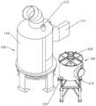
FIG. 1 is a schematic structural diagram of an embodiment of a purification and whitening device for acid production tail gas according to the present invention;
FIG. 2 is a schematic structural view of a purification apparatus according to an embodiment of the present invention;
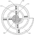
fig. 3 is a cross-sectional view of a baffle of an embodiment of the present invention;
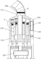
FIG. 4 is a cross-sectional view of a purification apparatus according to an embodiment of the present invention;
FIG. 5 is an enlarged view taken at A in FIG. 4;
FIG. 6 is an enlarged view at B in FIG. 4;
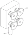
fig. 7 is a schematic structural diagram of a second showerhead according to an embodiment of the invention.
In the figure: 100. a purification device; 110. a purification cartridge; 120. a baffle; 130. a reaction chamber; 131. an air inlet; 132. a liquid outlet; 133. a liquid inlet; 134. an air outlet; 135. a liquid inlet pipe; 210. a first nozzle; 220. a second nozzle; 230. a water pump; 240. a water pumping pipe; 310. an overflow cylinder; 320. a collection box; 400. a stirring device; 410. a mixing drum; 420. a discharge outlet; 430. a recovery port; 500. a demister; 510. a defogging plate.
Detailed Description
The technical solutions in the embodiments of the present invention will be clearly and completely described below with reference to the drawings in the embodiments of the present invention, and it is obvious that the described embodiments are only a part of the embodiments of the present invention, and not all of the embodiments. All other embodiments, which can be derived by a person skilled in the art from the embodiments given herein without making any creative effort, shall fall within the protection scope of the present invention.
An embodiment of the acid production tail gas purification and whitening device of the invention is shown in fig. 1 to 7: a purification and whitening device for acid making tail gas comprises a purification device 100, a stirring device 400 and a demister 500.
The purification apparatus 100 includes a purification cartridge 110, a baffle 120, a spray structure, and a precipitation structure. The purification cartridge 110 is vertically disposed. The baffle 120 is vertically disposed and fixed on the inner circumferential wall of the purification cartridge 110. The cross section of the baffle 120 is a vortex line. The upper end of the guide plate 120 is hermetically provided with a top plate, and the lower end is hermetically provided with a bottom plate. The outer end of the baffle 120 is provided with an air inlet 131 and an air outlet 132, and the inner end is provided with an air inlet 133 and an air outlet 134. The baffle 120, the top plate and the bottom plate enclose a vortex-shaped reaction chamber 130.
The spray structure comprises a first spray piece and a second spray piece. The first spray member includes a first spray head 210. The first nozzle 210 is installed at the inner end of the baffle 120 and communicates with the liquid inlet 133. The second spray member is provided in plural, and is spaced from inside to outside along the guide plate 120, and includes a second spray head 220. The second spray head 220 is installed on the guide plate 120, and a suction pump 230 is provided at the lower side. The water outlet pipe of the water pump 230 is communicated with the second spray head 220. A suction pipe 240 is provided below the suction pump 230. The water pumping pipe 240 is vertically arranged, the upper end of the water pumping pipe is communicated with the water inlet pipe of the water pumping pump 230, and the lower end of the water pumping pipe is arranged at the bottom of the reaction chamber 130.
The settling structure includes a plurality of overflow cartridges 310. A plurality of overflow cylinders 310 are distributed along the guide plate 120 from the inside to the outside at the bottom of the reaction chamber 130, and the upper end is communicated with the reaction chamber 130 for collecting the by-products of the precipitated crystals. The stirring device 400 is disposed outside the purifying cylinder 110, and is used for adding the limestone solution into the reaction chamber 130 from the liquid inlet 133 after fully stirring the limestone solution, and recovering and fully stirring the limestone solution flowing out of the liquid outlet 132. The demister 500 is disposed above the air outlet 134 and above the baffle 120. After being stirred by the stirring device 400, the limestone solution enters the reaction chamber 130 from the liquid inlet 133 at the center of the reaction chamber 130, flows in a vortex shape from inside to outside along the guide plate 120, and moves forward to the liquid outlet 132 and then is recycled to the stirring device 400, so that the limestone solution forms a circulating flow, after the overflow cylinder 310 is filled, the water pump 230 is started to pump the slurry at the bottom of the reaction chamber 130 to the second nozzle 220 for spraying, the tail gas enters the reaction chamber 130 from the air inlet 131 at the outer side of the reaction chamber 130, moves forward in a vortex shape from outside to inside along the guide plate 120, and is discharged from the air outlet 134 after being subjected to a purification reaction with the sprayed limestone solution. The vortex-shaped reaction cavity 130 of the device increases the space and the stroke of gas-liquid reaction under the condition of the same device and the same line volume, and promotes the purification and absorption of substances such as sulfur dioxide in tail gas. Meanwhile, the limestone solution after reaction flows back to the stirring device 400 to be stirred again, so that the disturbance to the precipitate is avoided, and the generation of precipitate crystallization is facilitated.
In this embodiment, the height of the bottom of the reaction chamber 130 is gradually decreased from inside to outside to promote the flow of the limestone solution from inside to outside along the flow guide plate 120 after the limestone solution enters the reaction chamber 130 from the liquid inlet pipe 135.
In this embodiment, the height of the top of the reaction chamber 130 is gradually reduced from inside to outside, so that the area of the vertical cross section of the reaction chamber 130 is the same, and the lifting force of a spiral is provided for the acid making tail gas, and meanwhile, the area of the vertical cross section of the reaction chamber 130 is the same, so that the flow speed of the tail gas in the reaction chamber 130 is uniform, the slow condition cannot occur, and the desulfurization purification reaction effect is better.
In the present embodiment, the demister 500 includes a plurality of demister plates 510. A plurality of defogging boards 510 interval distribution, and the clearance is the broken line form between two adjacent defogging boards 510 for make the better condensation of vapor in the tail gas.
In this embodiment, a collection tank 320 is provided below the overflow cylinder 310. The collecting tank 320 is communicated with the overflow cylinder 310 through a collecting pipe. The collecting pipe is provided with a valve. The limestone solution after the reaction flows back to the stirring device 400 to be stirred again, so that the disturbance to the precipitate is avoided.
In the present embodiment, the stirring device 400 includes a stirring cylinder 410, a stirring shaft, and a stirring blade. The mixing drum 410 is vertically disposed. The lower end of the mixing drum 410 is provided with a discharge outlet 420. The discharge port 420 and the liquid inlet 133 are communicated by a hose. The upper end of the mixing drum 410 is provided with a recovery port 430. The recovery port 430 and the liquid outlet 132 are communicated by a hose. The stirring shaft is rotatably installed in the stirring cylinder 410. The stirring vane is fixed at the lower end of the stirring shaft and is used for fully stirring the limestone solution.
In this embodiment, the collection box 320 is provided with a drain at the bottom for recycling.
In this embodiment, a plurality of legs are fixedly installed at the bottom of the purification cartridge 110 to stabilize the apparatus.
In this embodiment, a discharge pipe is connected to the air outlet 134 for discharging the purified exhaust gas to a designated area.
In this embodiment, the liquid inlet 133 is connected to a liquid inlet pipe 135 for feeding the limestone solution in the mixing drum 410 into the reaction chamber 130.
With the above embodiments, the usage principle and the working process of the present invention are as follows: when the device is used, limestone solution enters the reaction cavity 130 from the liquid inlet 133 in the center of the reaction cavity 130 after being stirred by the stirring device 400, flows in a vortex shape from inside to outside along the guide plate 120, and is recycled to the stirring device 400 after advancing to the liquid outlet 132, so that the limestone solution forms a circulating flow, after the overflow cylinder 310 is filled, the water suction pump 230 is started to suck slurry at the bottom of the reaction cavity 130 to the second spray head 220 for spraying, then tail gas enters the reaction cavity 130 from the air inlet 131 outside the reaction cavity 130, advances in a vortex shape from outside to inside along the guide plate 120, is purified and reacted with the sprayed limestone solution, and is discharged from the air outlet 134, and precipitates generated after reaction are gradually deposited in the overflow cylinder 310. After a certain amount has been accumulated, the valve is opened to allow the sediment to enter the collection tank 320 for recovery.
The vortex-shaped reaction cavity 130 of the device increases the space and the stroke of gas-liquid reaction under the condition of the same device and the same line volume, and promotes the purification and absorption of substances such as sulfur dioxide in tail gas. Meanwhile, the limestone solution after reaction flows back to the stirring device 400 to be stirred again, so that the disturbance to the precipitate is avoided, and the generation of precipitate crystallization is facilitated.
Further, the height of the bottom of the reaction chamber 130 is gradually reduced from inside to outside, so that the limestone solution enters the reaction chamber 130 from the liquid inlet pipe 135 and then flows out from inside to outside along the flow guide plate 120. Simultaneously, the height of the top of the reaction cavity 130 is gradually reduced from inside to outside, so that the area of the vertical section of the reaction cavity 130 is the same, on one hand, a spiral lifting force is provided for the acid making tail gas, on the other hand, the flowing speed of the tail gas in the reaction cavity 130 is uniform, the condition of fast and slow operation can not occur, and the desulfurization purification reaction effect is better.
The above description is only for the purpose of illustrating the preferred embodiments of the present invention and is not to be construed as limiting the invention, and any modifications, equivalents, improvements and the like that fall within the spirit and principle of the present invention are intended to be included therein.
Claims (10)
1. The utility model provides a system acid tail gas purifies and takes off white device which characterized in that: comprises a purifying device, a stirring device and a demister;
the purification device comprises a purification cylinder, a guide plate, a spraying structure and a precipitation structure;
the purifying cylinder is vertically arranged;
the guide plate is vertically arranged and fixed on the inner peripheral wall of the purification cylinder; the cross section of the guide plate is a vortex line; the upper end of the guide plate is hermetically provided with a top plate, and the lower end of the guide plate is hermetically provided with a bottom plate; the outer end of the guide plate is provided with an air inlet and an liquid outlet, and the inner end of the guide plate is provided with a liquid inlet and an air outlet; the guide plate, the top plate and the bottom plate form a vortex-shaped reaction cavity;
the spraying structure comprises a first spraying piece and a second spraying piece;
the first spraying piece comprises a first spray head; the first spray head is arranged at the inner end of the guide plate and is communicated with the liquid inlet;
the second spraying parts are provided with a plurality of second spraying parts which are distributed at intervals from inside to outside along the guide plate and comprise second spray heads; the second spray nozzle is arranged on the guide plate, and a water suction pump is arranged at the lower side of the second spray nozzle; the water outlet pipe of the water pump is communicated with the second spray head; a water pumping pipe is arranged below the water pumping pump; the water pumping pipe is vertically arranged, the upper end of the water pumping pipe is communicated with a water inlet pipe of the water pumping pump, and the lower end of the water pumping pipe is arranged at the bottom of the reaction cavity;
the sedimentation structure comprises a plurality of overflow cylinders; the overflow cylinders are distributed at the bottom of the reaction cavity from inside to outside along the guide plate, and the upper ends of the overflow cylinders are communicated with the reaction cavity and used for collecting by-products of precipitated crystals;
the stirring device is arranged outside the purifying cylinder and is used for adding the limestone solution into the reaction cavity from the liquid inlet after fully stirring the limestone solution, and recovering and fully stirring the limestone solution flowing out of the liquid outlet;
the demister is arranged above the air outlet and above the guide plate.
2. The acid making tail gas purifying and whitening device according to claim 1, characterized in that: the height of the bottom of the reaction cavity is gradually reduced from inside to outside.
3. The acid making tail gas purifying and whitening device according to claim 2, characterized in that: the height of the top of the reaction cavity is gradually reduced from inside to outside so that the areas of the vertical sections of the reaction cavity are the same.
4. The acid making tail gas purifying and whitening device according to claim 3, characterized in that: the demister comprises a plurality of demister plates; the plurality of defogging plates are distributed at intervals, and the gap between every two adjacent defogging plates is in a folded line shape.
5. The acid making tail gas purifying and whitening device according to claim 1, characterized in that: a collecting box is arranged below the overflow cylinder; the collecting box is communicated with the overflow cylinder through a collecting pipe; the collecting pipe is provided with a valve.
6. The acid making tail gas purifying and whitening device according to claim 1, characterized in that: the stirring device comprises a stirring cylinder, a stirring shaft and stirring blades; the mixing drum is vertically arranged; a discharge port is arranged at the lower end of the stirring cylinder; the discharge port is communicated with the liquid inlet through a hose; a recovery port is arranged at the upper end of the mixing drum; the recycling port is communicated with the liquid outlet through a hose; the stirring shaft is rotatably arranged in the stirring cylinder; the stirring blade is fixed at the lower end of the stirring shaft.
7. The acid making tail gas purifying and whitening device according to claim 5, characterized in that: the bottom of the collecting box is provided with a discharge hole.
8. The acid making tail gas purifying and whitening device according to claim 1, characterized in that: a plurality of support legs are fixedly arranged at the bottom of the purifying cylinder.
9. The acid making tail gas purifying and whitening device according to claim 1, characterized in that: the air outlet is connected with a discharge pipe.
10. The acid making tail gas purifying and whitening device according to claim 1, characterized in that: the liquid inlet is connected with a liquid inlet pipe.
Priority Applications (1)
| Application Number | Priority Date | Filing Date | Title |
|---|---|---|---|
| CN202210780633.3A CN114870606B (en) | 2022-07-05 | 2022-07-05 | Acid making tail gas purifying and whitening device |
Applications Claiming Priority (1)
| Application Number | Priority Date | Filing Date | Title |
|---|---|---|---|
| CN202210780633.3A CN114870606B (en) | 2022-07-05 | 2022-07-05 | Acid making tail gas purifying and whitening device |
Publications (2)
| Publication Number | Publication Date |
|---|---|
| CN114870606A true CN114870606A (en) | 2022-08-09 |
| CN114870606B CN114870606B (en) | 2022-09-23 |
Family
ID=82683242
Family Applications (1)
| Application Number | Title | Priority Date | Filing Date |
|---|---|---|---|
| CN202210780633.3A Active CN114870606B (en) | 2022-07-05 | 2022-07-05 | Acid making tail gas purifying and whitening device |
Country Status (1)
| Country | Link |
|---|---|
| CN (1) | CN114870606B (en) |
Cited By (1)
| Publication number | Priority date | Publication date | Assignee | Title |
|---|---|---|---|---|
| CN117244487A (en) * | 2023-11-20 | 2023-12-19 | 苏州智程半导体科技股份有限公司 | Mixing arrangement of isopropyl alcohol and nitrogen gas |
Citations (10)
| Publication number | Priority date | Publication date | Assignee | Title |
|---|---|---|---|---|
| US5837213A (en) * | 1995-05-30 | 1998-11-17 | Chiyoda Corporation | Process for the desulfurization of sulfurous acid gas-containing waste gas |
| CN2326318Y (en) * | 1998-01-14 | 1999-06-30 | 陈火其 | Flue-gas desulfurizing and dust-removing apparatus |
| CN105327581A (en) * | 2015-10-31 | 2016-02-17 | 张继金 | Cyclone-water-curtain dust removing device suitable for recycling high-temperature tail gas with dust |
| CN206549374U (en) * | 2017-01-22 | 2017-10-13 | 河南心连心化肥有限公司 | A kind of labyrinth type cyclone dust catcher |
| CN110102079A (en) * | 2019-05-09 | 2019-08-09 | 山东明晟化工工程有限公司 | A kind of acidic crystallization device of system for desulfuration and denitration |
| CN209438345U (en) * | 2018-12-27 | 2019-09-27 | 朱敬 | The device of sulfur dioxide in a kind of efficient removal coal-fired flue-gas |
| CN110314522A (en) * | 2019-08-07 | 2019-10-11 | 苏州仕净环保科技股份有限公司 | A kind of offgas fractionation processing system |
| CN110711448A (en) * | 2019-11-27 | 2020-01-21 | 上海电力大学 | Spiral dust collector falls in slope |
| CN111773859A (en) * | 2020-07-15 | 2020-10-16 | 谢树彩 | Spiral air purification equipment |
| CN114191972A (en) * | 2021-11-09 | 2022-03-18 | 太仓市宇格明叶环保设备有限公司 | Fish scale-shaped stacked rain curtain type desulfurization spray tower and working method thereof |
-
2022
- 2022-07-05 CN CN202210780633.3A patent/CN114870606B/en active Active
Patent Citations (10)
| Publication number | Priority date | Publication date | Assignee | Title |
|---|---|---|---|---|
| US5837213A (en) * | 1995-05-30 | 1998-11-17 | Chiyoda Corporation | Process for the desulfurization of sulfurous acid gas-containing waste gas |
| CN2326318Y (en) * | 1998-01-14 | 1999-06-30 | 陈火其 | Flue-gas desulfurizing and dust-removing apparatus |
| CN105327581A (en) * | 2015-10-31 | 2016-02-17 | 张继金 | Cyclone-water-curtain dust removing device suitable for recycling high-temperature tail gas with dust |
| CN206549374U (en) * | 2017-01-22 | 2017-10-13 | 河南心连心化肥有限公司 | A kind of labyrinth type cyclone dust catcher |
| CN209438345U (en) * | 2018-12-27 | 2019-09-27 | 朱敬 | The device of sulfur dioxide in a kind of efficient removal coal-fired flue-gas |
| CN110102079A (en) * | 2019-05-09 | 2019-08-09 | 山东明晟化工工程有限公司 | A kind of acidic crystallization device of system for desulfuration and denitration |
| CN110314522A (en) * | 2019-08-07 | 2019-10-11 | 苏州仕净环保科技股份有限公司 | A kind of offgas fractionation processing system |
| CN110711448A (en) * | 2019-11-27 | 2020-01-21 | 上海电力大学 | Spiral dust collector falls in slope |
| CN111773859A (en) * | 2020-07-15 | 2020-10-16 | 谢树彩 | Spiral air purification equipment |
| CN114191972A (en) * | 2021-11-09 | 2022-03-18 | 太仓市宇格明叶环保设备有限公司 | Fish scale-shaped stacked rain curtain type desulfurization spray tower and working method thereof |
Cited By (2)
| Publication number | Priority date | Publication date | Assignee | Title |
|---|---|---|---|---|
| CN117244487A (en) * | 2023-11-20 | 2023-12-19 | 苏州智程半导体科技股份有限公司 | Mixing arrangement of isopropyl alcohol and nitrogen gas |
| CN117244487B (en) * | 2023-11-20 | 2024-02-09 | 苏州智程半导体科技股份有限公司 | Mixing arrangement of isopropyl alcohol and nitrogen gas |
Also Published As
| Publication number | Publication date |
|---|---|
| CN114870606B (en) | 2022-09-23 |
Similar Documents
| Publication | Publication Date | Title |
|---|---|---|
| CN101549235B (en) | Conjoined wet-type dust cleaning and desulfurizing device | |
| CN1712113A (en) | Smoke desulfidation from amino bialkali method | |
| CN102580486A (en) | Novel zinc oxide desulfurization method and device | |
| CN114870606B (en) | Acid making tail gas purifying and whitening device | |
| CN104226102B (en) | A kind of aluminium electrolytic flue horizontal spraying desulfurizer and method | |
| CN108854499A (en) | A kind of furfural dregs boiler smoke magnesia FGD purification device | |
| CN109364747A (en) | A kind of collecting smoke dust from coke oven desulphurization system and technique | |
| PL179681B1 (en) | Apparatus for wet desilphurisation of exhaust gas | |
| CN211358336U (en) | High-efficient deacidification smoke abatement device of industrial exhaust environmental protection | |
| CN102151480B (en) | Boiler flue gas desulfurization method and device | |
| CN111603903A (en) | Double-alkali desulphurization device | |
| CN216426942U (en) | Special desulfurization equipment of waste water treatment | |
| CN215233270U (en) | Semi-dry desulfurization device | |
| CN205868002U (en) | Flue gas desulfurization reaction tower | |
| CN211435701U (en) | Desulfurizing tower | |
| CN204107322U (en) | A kind of aluminium electrolytic flue horizontal spraying desulfurizer | |
| CN212236674U (en) | Boiler waste gas's processing apparatus | |
| CN103977697B (en) | A kind of box flue gas purification system | |
| RU2601332C2 (en) | Method of producing highly pure calcium chloride solution | |
| CN112569733A (en) | Sodium metabisulfite tail gas cleanup unit | |
| CN202315621U (en) | Flue gas purification tower of boiler | |
| CN219111287U (en) | Desulfurizing tower | |
| CN220257645U (en) | Desulfurization system for oil-based rock debris calcination treatment | |
| CN110141963A (en) | Flue gas desulfurization denitration dust-removing device | |
| CN2688366Y (en) | Flue desulfurizing resources apparatus |
Legal Events
| Date | Code | Title | Description |
|---|---|---|---|
| PB01 | Publication | ||
| PB01 | Publication | ||
| SE01 | Entry into force of request for substantive examination | ||
| SE01 | Entry into force of request for substantive examination | ||
| GR01 | Patent grant | ||
| GR01 | Patent grant |