CN114859524B - Ultra-short-focus optical system and projection equipment - Google Patents
Ultra-short-focus optical system and projection equipment Download PDFInfo
- Publication number
- CN114859524B CN114859524B CN202210791259.7A CN202210791259A CN114859524B CN 114859524 B CN114859524 B CN 114859524B CN 202210791259 A CN202210791259 A CN 202210791259A CN 114859524 B CN114859524 B CN 114859524B
- Authority
- CN
- China
- Prior art keywords
- lens
- rear lens
- mirror
- optical system
- optical axis
- Prior art date
- Legal status (The legal status is an assumption and is not a legal conclusion. Google has not performed a legal analysis and makes no representation as to the accuracy of the status listed.)
- Active
Links
Images


Classifications
-
- G—PHYSICS
- G02—OPTICS
- G02B—OPTICAL ELEMENTS, SYSTEMS OR APPARATUS
- G02B13/00—Optical objectives specially designed for the purposes specified below
- G02B13/001—Miniaturised objectives for electronic devices, e.g. portable telephones, webcams, PDAs, small digital cameras
- G02B13/0055—Miniaturised objectives for electronic devices, e.g. portable telephones, webcams, PDAs, small digital cameras employing a special optical element
- G02B13/006—Miniaturised objectives for electronic devices, e.g. portable telephones, webcams, PDAs, small digital cameras employing a special optical element at least one element being a compound optical element, e.g. cemented elements
-
- G—PHYSICS
- G02—OPTICS
- G02B—OPTICAL ELEMENTS, SYSTEMS OR APPARATUS
- G02B13/00—Optical objectives specially designed for the purposes specified below
- G02B13/001—Miniaturised objectives for electronic devices, e.g. portable telephones, webcams, PDAs, small digital cameras
- G02B13/0015—Miniaturised objectives for electronic devices, e.g. portable telephones, webcams, PDAs, small digital cameras characterised by the lens design
- G02B13/002—Miniaturised objectives for electronic devices, e.g. portable telephones, webcams, PDAs, small digital cameras characterised by the lens design having at least one aspherical surface
- G02B13/0035—Miniaturised objectives for electronic devices, e.g. portable telephones, webcams, PDAs, small digital cameras characterised by the lens design having at least one aspherical surface having three lenses
-
- G—PHYSICS
- G03—PHOTOGRAPHY; CINEMATOGRAPHY; ANALOGOUS TECHNIQUES USING WAVES OTHER THAN OPTICAL WAVES; ELECTROGRAPHY; HOLOGRAPHY
- G03B—APPARATUS OR ARRANGEMENTS FOR TAKING PHOTOGRAPHS OR FOR PROJECTING OR VIEWING THEM; APPARATUS OR ARRANGEMENTS EMPLOYING ANALOGOUS TECHNIQUES USING WAVES OTHER THAN OPTICAL WAVES; ACCESSORIES THEREFOR
- G03B21/00—Projectors or projection-type viewers; Accessories therefor
- G03B21/14—Details
- G03B21/142—Adjusting of projection optics
Abstract
The invention relates to the technical field of optical projection equipment, in particular to an ultra-short-focus optical system and projection equipment. The imaging optical axis direction imaging optical system comprises a front group lens, a middle group lens, a rear group lens and a reflector which are sequentially arranged at intervals; the direction of the imaging optical axis is from the first front lens to the reflector; the front lens group comprises: the first front lens, the second front double-cemented lens and the third front triple-cemented lens are sequentially arranged at intervals along the imaging optical axis direction; the middle group lens group comprises: the first middle lens and the second middle double-cemented lens are sequentially arranged at intervals along the direction of the imaging optical axis; the rear lens group includes: and the first rear lens, the second rear lens, the third rear lens and the fourth rear lens are sequentially arranged at intervals along the imaging optical axis direction. Therefore, the optical system in the invention has shorter length and smaller lens caliber, thereby realizing the effect of reducing volume and weight.
Description
Technical Field
The invention relates to the technical field of optical projection equipment, in particular to an ultra-short-focus optical system and projection equipment.
Background
With the continuous development of projection technology, projectors have been widely applied to the fields of household, education, office and the like, wherein, ultra-short focus projection can project large-size pictures under the condition of short-distance projection, and is popular with consumers. In the related art, under the requirements that the DMD is 0.37, the projection size is 80-120 inches, and the projection ratio is less than 0.2, the volume of the ultra-short-focus optical system is large, so that the miniaturization of the projection equipment is not facilitated, and the portability of the projection equipment is reduced.
Disclosure of Invention
Accordingly, the present invention is directed to an ultra-short focus optical system and a projection apparatus, which at least partially solve the problems of the prior art.
According to a first aspect of the present invention, there is provided an ultra-short focus optical system comprising:
the front group lens, the middle group lens, the rear group lens and the reflecting mirror are sequentially arranged at intervals along the direction of an imaging optical axis; the imaging optical axis direction is the direction from the first front lens to the reflector;
the front lens group comprises:
the first front lens, the second front double cemented lens and the third front triple cemented lens are sequentially arranged at intervals along the imaging optical axis direction;
the surface types corresponding to the first front lens, the second front double-cemented lens and the third front triple-cemented lens are all standard spherical surfaces;
the surface types of the first front lens, the second front double-cemented lens and the third front triple-cemented lens arranged along the imaging optical axis direction meet the following conditions:

wherein, R is the central curvature radius of the mirror surface corresponding to the standard spherical surface;
the third front third cemented lens is provided with a first sub-lens, a second sub-lens and a third sub-lens in sequence along the imaging optical axis direction, and the abbe numbers and refractive indexes corresponding to the first sub-lens, the second sub-lens and the third sub-lens are as follows:

the middle group lens group comprises:
the first middle lens and the second middle double-cemented lens are sequentially arranged at intervals along the direction of the imaging optical axis;
the rear lens group includes:
follow first rear lens, second rear lens, third rear lens and the fourth rear lens that imaging optical axis direction interval set gradually, first rear lens, second rear lens, third rear lens and fourth rear lens all can be followed and preset the route and removed, preset the route with imaging optical axis direction is parallel.
According to a second aspect of the present invention, there is provided a projection apparatus comprising:
an ultra-short-focus optical system as described above; and
the ultrashort-focus optical system is arranged in the shell.
The ultra-short-focus optical system is provided with a front group lens, a middle group lens, a rear group lens and a reflector which are sequentially arranged at intervals along the propagation direction of the imaging light. And a third cemented lens, namely a third front cemented lens, is arranged at the last of the front lens group, the third front cemented lens is formed by combining three sub-lenses with different refractive indexes and abbe numbers, and the cemented lens formed by the three sub-lenses defined in the invention has better light ray adjustment (deflection) capability and chromatic aberration correction capability compared with the optical system formed by the existing double cemented lens and/or single lens, so that the chromatic aberration of the whole optical system can be reduced by matching the cemented lens and the rest lenses in the invention, thereby improving the imaging quality of the whole optical system. Meanwhile, the tri-cemented lens has higher deflection and adjustment capability on the whole light, under the condition of not influencing the whole imaging quality, compared with the projection system on the same condition on the market at present, the whole system has fewer lenses, and the adjustment on the imaging light can be completely carried out within a shorter distance by matching with the adjustment on the other mirror surfaces, so that the total length of the optical system in the invention can be shortened, and the total length of the optical system in the invention can be controlled to be less than 180mm.
In addition, through other lenses in the preceding lens group of cooperating, can make the formation of image light gather together more, from this, the area that the formation of image light through the emergent of preceding lens group corresponds the cross-section that forms is littleer, and then can reduce the lens bore of follow-up lens, because, the bore size of first back lens and speculum can influence final casing equipment's size in actual installation, mainly for can influencing the biggest diameter size of casing equipment. Therefore, in the optical system of the present invention, since the imaging light is more gathered, the first rear lens and the reflector with smaller apertures may be used, specifically, the aperture of the first rear lens is 28mm, and the aperture of the reflector is 43mm.
Therefore, the optical system in the invention has shorter length, fewer lenses and smaller lens caliber, thereby realizing the effect of reducing volume and weight.
Drawings
In order to more clearly illustrate the technical solutions of the embodiments of the present invention, the drawings required to be used in the embodiments will be briefly described below, and it is obvious that the drawings in the following description are only some embodiments of the present invention, and it is obvious for those skilled in the art that other drawings can be obtained according to the drawings without creative efforts.
Fig. 1 is a schematic structural diagram of an ultra-short-focus optical system according to an embodiment of the present invention.
Fig. 2 is a schematic diagram of TV distortion of an ultra-short-focus optical system according to an embodiment of the present invention.
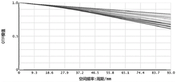
FIG. 3 is an MTF graph of an ultra-short-focus optical system with a projection dimension of 80 inches according to an embodiment of the present invention.
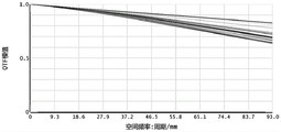
FIG. 4 is an MTF graph of an ultra-short-focus optical system with a projection size of 100 inches according to an embodiment of the present invention.
FIG. 5 is an MTF graph of an ultra-short-focus optical system with a projection size of 120 inches according to an embodiment of the present invention.
Fig. 6 is a schematic structural diagram (only a part of which is shown) of an ultra-short-focus optical system according to an embodiment of the present invention.
Reference numerals are as follows:
1. a DMD chip; 2. a first front lens; 3. a second front doublet lens; 4. a third front cemented lens; 5. a first middle lens; 6. a second middle doublet cemented lens; 7. a first rear lens; 8. a second rear lens; 9. a third rear lens; 10. a fourth rear lens; 11. a mirror; 12. an imaging optical axis.
Detailed Description
Embodiments of the present invention are described in detail below with reference to the accompanying drawings.
It should be noted that, in the case of no conflict, the features in the following embodiments and examples may be combined with each other; moreover, all other embodiments that can be derived by one of ordinary skill in the art from the embodiments disclosed herein without making any creative effort fall within the scope of the present disclosure.
It is noted that various aspects of the embodiments are described below within the scope of the appended claims. It should be apparent that the aspects described herein may be embodied in a wide variety of forms and that any specific structure and/or function described herein is merely illustrative. Based on the disclosure, one skilled in the art should appreciate that one aspect described herein may be implemented independently of any other aspects and that two or more of these aspects may be combined in various ways. For example, an apparatus may be implemented and/or a method practiced using any number of the aspects set forth herein. In addition, such an apparatus may be implemented and/or such a method may be practiced using other structure and/or functionality in addition to or other than one or more of the aspects set forth herein.
According to a first aspect of the present invention, as shown in fig. 1, there is provided an ultra-short focus optical system comprising:
a front group lens, a middle group lens, a rear group lens and a reflector 11 which are arranged at intervals in sequence along the direction of an imaging optical axis 12; the direction of the imaging optical axis 12 is the direction from the first front lens 2 to the reflecting mirror 11, the first mirror surface and the second mirror surface in the present invention are two outer surfaces corresponding to any one lens unit, and one lens unit can be a single lens or an integral of a cemented lens.
The front lens group comprises:
the first front lens 2, the second front double-cemented lens 3 and the third front triple-cemented lens 4 are sequentially arranged at intervals along the direction of an imaging optical axis 12;
the corresponding surface types of the first front lens 2, the second front double-cemented lens 3 and the third front triple-cemented lens 4 are standard spherical surfaces;
the surface shapes of the first front lens 2, the second front doublet 3 and the third front triplet 4 arranged along the imaging optical axis 12 meet the following conditions:

wherein, R is the central curvature radius of the mirror surface corresponding to the standard spherical surface;
the third front third cemented lens is provided with a first sub-lens, a second sub-lens and a third sub-lens in sequence along the imaging optical axis direction, and the abbe numbers and refractive indexes corresponding to the first sub-lens, the second sub-lens and the third sub-lens are as follows:

the middle group lens group comprises:
the first middle lens 5 and the second middle double-cemented lens 6 are sequentially arranged at intervals along the direction of an imaging optical axis 12;
the surface types of the first middle lens 5 and the second middle double cemented lens 6 are both standard spherical surfaces. The surface type parameters of the first middle lens 5 and the second middle double cemented lens 6 satisfy the following conditions:

the rear lens group includes:
the first rear lens 7, the second rear lens 8, the third rear lens 9 and the fourth rear lens 10 are sequentially arranged along the imaging optical axis 12 at intervals, the first rear lens 7, the second rear lens 8, the third rear lens 9 and the fourth rear lens 10 can move along a preset path, and the preset path is parallel to the imaging optical axis 12.
The first rear lens 7, the second rear lens 8, the third rear lens 9 and the fourth rear lens 10 respectively have a first mirror surface and a second mirror surface, and the surface shapes of the fourth rear lens 10, the second rear lens 8 and the third rear lens 9 satisfy the following conditions:

wherein Z is the mirror depth value, the unit is millimeter, namely the axial value which takes the intersection point of each aspheric surface and the optical axis as the starting point and is parallel to the optical axis direction; c =1/R, where R is the radius of curvature of the center of the mirror in millimeters and c is the curvature of the center of the mirror; r is the height of the center of the mirror surface and the unit is millimeter; when the K coefficient is less than-1, the surface-shaped curve of the lens is a hyperbolic curve, and when the K coefficient is equal to-1, the surface-shaped curve of the lens is a parabola; when the K coefficient is between-1 and 0, the surface-shaped curve of the lens is an ellipse, when the K coefficient is equal to 0, the surface-shaped curve of the lens is a circle, and when the K coefficient is more than 0, the surface-shaped curve of the lens is an oblate; a is a 1 To a 8 Respectively representing coefficients corresponding to the radial coordinates;

the first mirror surface and the second mirror surface of the first rear lens 7 are both standard spherical surfaces, and the surface type of the first rear lens 7 satisfies the following conditions:

the surface shape of the reflecting mirror 11 satisfies the following conditions:


wherein Z is the mirror depth value, the unit is millimeter, namely the axial value which takes the intersection point of each aspheric surface and the optical axis as the starting point and is parallel to the optical axis direction; c =1/R, where R is the radius of curvature of the mirror center in millimeters and c is the curvature of the mirror center; r is the height of the center of the mirror surface and the unit is millimeter; when the K coefficient is less than-1, the surface-shaped curve of the lens is a hyperbolic curve, and when the K coefficient is equal to-1, the surface-shaped curve of the lens is a parabola; when the K coefficient is between-1 and 0, the surface-shaped curve of the lens is an ellipse, when the K coefficient is equal to 0, the surface-shaped curve of the lens is a circle, and when the K coefficient is more than 0, the surface-shaped curve of the lens is an oblate; a is a 1 To a 12 Respectively representing coefficients corresponding to the radial coordinates; rho i =x i +y i And x and y represent the horizontal and vertical coordinate values corresponding to the continuous points taken on the coordinates, namely, the horizontal and vertical coordinate values corresponding to each Z.
The ultra-short-focus optical system is provided with a front group lens, a middle group lens, a rear group lens and a reflector 11 which are sequentially arranged at intervals along the propagation direction of the imaging light. After being generated by the DMD chip 1, the imaging light enters the optical system of this embodiment from the first mirror surface of the first front lens 2, then enters the middle lens group and the rear lens group in sequence after being deflected and corrected by the second front double cemented lens 3 and the third front triple cemented lens 4, and finally is projected to the screen or the image receiving side by the reflector 11.
The last of the front lens group is provided with a tri-cemented lens, namely a third front tri-cemented lens 4, which has higher deflection and adjustment capability to light rays, so that imaging light rays can be adjusted to a larger extent, and meanwhile, the deflection adjustment of the imaging light rays can be completely performed within a shorter distance by matching with the adjustment of the first front lens 2 and the second front bi-cemented lens 3 in the front lens group to the imaging light rays, thereby meeting the requirement of imaging. Therefore, the total length of the optical system in the invention can be shortened, and particularly the total length of the optical system in the invention can be controlled to be less than 180mm. In addition, as can be seen from fig. 2, the optical system in this embodiment can also ensure that the final imaged picture has smaller TV distortion (specifically less than 0.1%), thereby ensuring that the whole picture has higher reality and reducing the distortion degree.
In addition, the front group lens group can enable imaging light rays to be gathered more, so that the area of a cross section formed by the imaging light rays emitted by the front group lens group correspondingly is smaller, and the lens aperture of a subsequent lens can be reduced. Therefore, the optical system has shorter length and smaller lens caliber, thereby realizing the effects of reducing volume and weight. In addition, in the present embodiment, the third front third cemented lens 4 has higher deflection and adjustment capability for light, so that the total number of used lenses can be reduced. At least one lens can be reduced relative to existing optical systems, thereby further reducing the length and weight of the optical fiber system.
As another possible embodiment of the present application, the mirror spacing between the first rear lens 7, the second rear lens 8, the third rear lens 9, the fourth rear lens 10 and the mirror 11 satisfies the following condition:
L1=(1-K1)X1;L2=(1-K2)X2;L3=(1-K3)X3;L4=(1-K4)X4;
wherein, as shown in fig. 6, L4 is a distance between the fourth rear lens 10 and the reflecting mirror 11; l3 is the distance between the fourth rear lens 10 and the third rear lens 9; l2 is the distance between the third rear lens 9 and the second rear lens 8; l1 is the distance between the second rear lens 8 and the first rear lens 7; x1, X2, X3 and X4 are the values of L1, L2, L3 and L4 respectively when the projection size is 100 inches; k1, K2, K3 and K4 are all coefficient of variation, wherein K1E [ -0.01,0.009], K2E [ -0.03,0.045], K3E [ -0.0095,0.0087], K4E [ -0.032,0.04].
Preferably, L1=15.8mm, L2=14.3mm, L3=2.3mm, and L4=14mm. That is, when the projected size is 100 inches, L1= X1=15.8mm; l2= X2=14.3mm; l3= X3=2.3mm; l4= X4=14mm. As can be seen from fig. 4, the image can be ensured to have good clarity and reality in the state of the mirror pitch.
When the projection size is 80 inches, K1= -0.01, K2= -0.03, K3= -0.0095, and K4= -0.032.
When the projection size is 120 inches, K1=0.009, K2=0.045, K3=0.0087, and K4=0.04.
The existing optical system can generally ensure that an imaging picture has higher definition under the main projection size, namely has a larger OTF module value, but the definition can be reduced when the size of the projection picture is adjusted, thereby reducing the imaging quality of the picture. When the projection size of the optical system in this embodiment changes, the distance between the rear lens group and the reflecting mirror 11 can be adjusted according to the above manner, so that the imaging picture under different projection sizes can be controlled to have higher definition, the influence on the definition of the picture when the projection size changes can be further reduced, and the imaging quality is finally improved.
Meanwhile, as shown in fig. 3 to 5, generally, the definition of the image can be ensured when the OTF module value is greater than 0.5, and when the projection size of the optical system in this embodiment is 80 inches, 100 inches or 120 inches, the OTF module value can be ensured to be more than 0.60, so that it can be known that the image of the optical system in this embodiment has higher definition in different projection sizes, and the imaging quality is further improved. In addition, the adjustment mode can also ensure that the projection picture has smaller TV distortion in the change process of the projection size, thereby ensuring that the whole picture has higher authenticity and reducing the distortion degree.
According to a second aspect of the present invention, there is provided a projection apparatus comprising:
the ultra-short-focus optical system described above; and
the ultra-short-focus optical system is arranged in the shell.
The above description is only for the specific embodiments of the present invention, but the scope of the present invention is not limited thereto, and any changes or substitutions that can be easily conceived by those skilled in the art within the technical scope of the present invention are included in the scope of the present invention. Therefore, the protection scope of the present invention shall be subject to the protection scope of the claims.
Claims (10)
1. An ultra-short-focus optical system, comprising:
the front group lens, the middle group lens, the rear group lens and the reflecting mirror are sequentially arranged at intervals along the direction of an imaging optical axis; the direction of the imaging optical axis is from the first front lens to the reflector;
the front group lens group comprises:
the first front lens, the second front double-cemented lens and the third front triple-cemented lens are sequentially arranged at intervals along the imaging optical axis direction;
the surface types corresponding to the first front lens, the second front double-cemented lens and the third front triple-cemented lens are all standard spherical surfaces;
the surface types of the first front lens, the second front double-cemented lens and the third front triple-cemented lens arranged along the imaging optical axis direction meet the following conditions:

wherein, R is the central curvature radius of the mirror surface corresponding to the standard spherical surface;
the third front third cemented lens is sequentially provided with a first sub-lens, a second sub-lens and a third sub-lens along the imaging optical axis direction, and the abbe numbers and refractive indexes corresponding to the first sub-lens, the second sub-lens and the third sub-lens are as follows:

the middle group lens group comprises:
the first middle lens and the second middle double-cemented lens are sequentially arranged at intervals along the direction of the imaging optical axis;
the rear lens group includes:
follow first rear lens, second rear lens, third rear lens and the fourth rear lens that imaging optical axis direction interval set gradually set up, first rear lens, second rear lens, third rear lens and fourth rear lens all can follow and predetermine the route and remove, predetermine the route with imaging optical axis direction is parallel.
2. An ultra-short-focus optical system as claimed in claim 1, wherein the first rear lens, the second rear lens, the third rear lens and the fourth rear lens have a first mirror surface and a second mirror surface, respectively, and the surface shapes of the fourth rear lens, the second rear lens and the third rear lens satisfy the following condition:

wherein Z is the mirror depth value, the unit is millimeter, namely the axial value which takes the intersection point of each aspheric surface and the optical axis as the starting point and is parallel to the optical axis direction; c =1/R, where R is the radius of curvature of the center of the mirror in millimeters and c is the curvature of the center of the mirror; r is the height of the center of the mirror surface and the unit is millimeter; when the K coefficient is less than-1, the surface-shaped curve of the lens is a hyperbolic curve, and when the K coefficient is equal to-1, the surface-shaped curve of the lens is a parabola; when the K coefficient is between-1 and 0, the surface-shaped curve of the lens is an ellipse, when the K coefficient is equal to 0, the surface-shaped curve of the lens is a circle, and when the K coefficient is more than 0, the surface-shaped curve of the lens is an oblate; a is 1 To a 8 Respectively representing coefficients corresponding to the radial coordinates;

the first mirror surface and the second mirror surface of the first rear lens are both standard spherical surfaces, and the surface type of the first rear lens meets the following conditions:

3. an ultra-short-focus optical system as claimed in claim 2, wherein the mirror pitch between the first rear lens, the second rear lens, the third rear lens, the fourth rear lens and the reflector satisfies the following condition:
L1=(1-K1)X1;L2=(1-K2)X2;L3=(1-K3)X3;L4=(1-K4)X4;
wherein L4 is a distance between the fourth rear lens and the mirror; the L3 is the distance between the fourth rear lens and the third rear lens; the L2 is the distance between a third rear lens and the second rear lens; the L1 is the distance between the second rear lens and the first rear lens; x1, X2, X3 and X4 are the values of L1, L2, L3 and L4 respectively when the projection size is 100 inches; k1, K2, K3 and K4 are all coefficient of variation, wherein, K1E [ -0.01,0.009], K2E [ -0.03,0.045], K3E [ -0.0095,0.0087], K4E [ -0.032,0.04].
4. An ultra-short focus optical system as claimed in claim 3, wherein L1=15.8mm, L2=14.3mm, L3=2.3mm, L4=14mm.
5. An ultra-short-focus optical system as claimed in claim 3, wherein when the projection size is 80 inches, K1= -0.01, K2= -0.03, K3= -0.0095, and K4= -0.032.
6. An ultra-short focus optical system as claimed in claim 3, wherein when the projection size is 120 inches, K1=0.009, K2=0.045, K3=0.0087, and K4=0.04.
7. An ultra-short focus optical system as claimed in claim 1, wherein the mirror has a surface shape satisfying the following condition:

wherein Z is mirror depth value in millimeter, i.e. with each aspheric surface and optical axisThe intersection point is taken as a starting point and is parallel to the axial value of the optical axis direction; c =1/R, where R is the radius of curvature of the center of the mirror in millimeters and c is the curvature of the center of the mirror; r is the height of the center of the mirror surface and the unit is millimeter; when the K coefficient is less than-1, the surface-shaped curve of the lens is a hyperbolic curve, and when the K coefficient is equal to-1, the surface-shaped curve of the lens is a parabola; when the K coefficient is between-1 and 0, the surface-shaped curve of the lens is an ellipse, when the K coefficient is equal to 0, the surface-shaped curve of the lens is a circle, and when the K coefficient is more than 0, the surface-shaped curve of the lens is an oblate; a is 1 To a 12 Respectively representing coefficients corresponding to the radial coordinates; rho i =x i +y i X and y represent horizontal and vertical coordinate values corresponding to continuous points taken on the coordinates, namely, the horizontal and vertical coordinate values corresponding to each Z;

8. an ultra-short-focus optical system as claimed in claim 1, wherein the first middle lens and the second middle doublet are both standard spherical surfaces.
9. An ultra-short-focus optical system as claimed in claim 8, wherein the surface parameters of the first middle lens and the second middle double cemented lens satisfy the following condition:

10. a projection device, comprising:
an ultra-short-focus optical system as claimed in any one of claims 1 to 9; and
the ultrashort-focus optical system is arranged in the shell.
Priority Applications (2)
| Application Number | Priority Date | Filing Date | Title |
|---|---|---|---|
| CN202210791259.7A CN114859524B (en) | 2022-07-07 | 2022-07-07 | Ultra-short-focus optical system and projection equipment |
| PCT/CN2023/094098 WO2024007740A1 (en) | 2022-07-07 | 2023-05-15 | Ultra-short throw optical system and projection apparatus |
Applications Claiming Priority (1)
| Application Number | Priority Date | Filing Date | Title |
|---|---|---|---|
| CN202210791259.7A CN114859524B (en) | 2022-07-07 | 2022-07-07 | Ultra-short-focus optical system and projection equipment |
Publications (2)
| Publication Number | Publication Date |
|---|---|
| CN114859524A CN114859524A (en) | 2022-08-05 |
| CN114859524B true CN114859524B (en) | 2022-10-25 |
Family
ID=82625719
Family Applications (1)
| Application Number | Title | Priority Date | Filing Date |
|---|---|---|---|
| CN202210791259.7A Active CN114859524B (en) | 2022-07-07 | 2022-07-07 | Ultra-short-focus optical system and projection equipment |
Country Status (2)
| Country | Link |
|---|---|
| CN (1) | CN114859524B (en) |
| WO (1) | WO2024007740A1 (en) |
Families Citing this family (1)
| Publication number | Priority date | Publication date | Assignee | Title |
|---|---|---|---|---|
| CN114859524B (en) * | 2022-07-07 | 2022-10-25 | 沂普光电(天津)有限公司 | Ultra-short-focus optical system and projection equipment |
Citations (15)
| Publication number | Priority date | Publication date | Assignee | Title |
|---|---|---|---|---|
| CN1161461A (en) * | 1995-06-02 | 1997-10-08 | 德克萨斯仪器股份有限公司 | Offset zoom lens for reflective light modulators |
| CN2609005Y (en) * | 2003-04-10 | 2004-03-31 | 昂纳明达网络技术(深圳)有限公司 | Wide angle projection optical system possessing long back focal distance |
| CN1661417A (en) * | 2004-02-24 | 2005-08-31 | 三星电子株式会社 | Retrofocus type projection optical system |
| JP2006215476A (en) * | 2005-02-07 | 2006-08-17 | Nitto Kogaku Kk | Lens system for projection, and projector apparatus |
| CN101147091A (en) * | 2005-03-25 | 2008-03-19 | 3M创新有限公司 | Wide angle projection lens having three groups |
| CN202383350U (en) * | 2011-11-23 | 2012-08-15 | 星盛光电股份有限公司 | Six-chip type projection lens module |
| JP2015215399A (en) * | 2014-05-08 | 2015-12-03 | 富士フイルム株式会社 | Projection lens and projection display device |
| JP2016099439A (en) * | 2014-11-19 | 2016-05-30 | 株式会社リコー | Projection optical system and image display device |
| CN107422458A (en) * | 2017-09-08 | 2017-12-01 | 杭州有人光电技术有限公司 | A kind of full HD projection lens of L-type short focus of low F numbers |
| CN109001895A (en) * | 2018-09-21 | 2018-12-14 | 杭州有人光电技术有限公司 | A kind of small-sized high definition ultra-short focus projection lens |
| CN111290100A (en) * | 2018-12-10 | 2020-06-16 | 青岛海信激光显示股份有限公司 | Projection lens and projection imaging system |
| CN112444930A (en) * | 2019-09-04 | 2021-03-05 | 青岛海信激光显示股份有限公司 | Projection lens, focusing method and device of projection lens and projector |
| CN112462491A (en) * | 2019-09-06 | 2021-03-09 | 扬明光学股份有限公司 | Projection lens and projector |
| CN114296217A (en) * | 2021-12-29 | 2022-04-08 | 青岛海信激光显示股份有限公司 | Projection lens and projection system |
| CN114296218A (en) * | 2021-12-29 | 2022-04-08 | 青岛海信激光显示股份有限公司 | Projection lens and projection system |
Family Cites Families (8)
| Publication number | Priority date | Publication date | Assignee | Title |
|---|---|---|---|---|
| CN201725088U (en) * | 2010-07-02 | 2011-01-26 | 星盛光电股份有限公司 | Miniature projection lens module |
| CN107490844B (en) * | 2012-10-25 | 2020-05-19 | 扬明光学股份有限公司 | Wide-angle projection lens |
| JP7040171B2 (en) * | 2018-03-19 | 2022-03-23 | セイコーエプソン株式会社 | Projection optical system and projection type image display device |
| JP2019164184A (en) * | 2018-03-19 | 2019-09-26 | セイコーエプソン株式会社 | Projection optical system and projection type image display unit |
| CN112540442A (en) * | 2019-09-04 | 2021-03-23 | 青岛海信激光显示股份有限公司 | Projection lens, focusing method and device of projection lens and projector |
| CN112882203A (en) * | 2021-03-22 | 2021-06-01 | 沂普光电(天津)有限公司 | Short-focus lens and short-focus optical system |
| CN113504633B (en) * | 2021-06-29 | 2022-10-18 | 青岛海信激光显示股份有限公司 | Projection system |
| CN114859524B (en) * | 2022-07-07 | 2022-10-25 | 沂普光电(天津)有限公司 | Ultra-short-focus optical system and projection equipment |
-
2022
- 2022-07-07 CN CN202210791259.7A patent/CN114859524B/en active Active
-
2023
- 2023-05-15 WO PCT/CN2023/094098 patent/WO2024007740A1/en unknown
Patent Citations (15)
| Publication number | Priority date | Publication date | Assignee | Title |
|---|---|---|---|---|
| CN1161461A (en) * | 1995-06-02 | 1997-10-08 | 德克萨斯仪器股份有限公司 | Offset zoom lens for reflective light modulators |
| CN2609005Y (en) * | 2003-04-10 | 2004-03-31 | 昂纳明达网络技术(深圳)有限公司 | Wide angle projection optical system possessing long back focal distance |
| CN1661417A (en) * | 2004-02-24 | 2005-08-31 | 三星电子株式会社 | Retrofocus type projection optical system |
| JP2006215476A (en) * | 2005-02-07 | 2006-08-17 | Nitto Kogaku Kk | Lens system for projection, and projector apparatus |
| CN101147091A (en) * | 2005-03-25 | 2008-03-19 | 3M创新有限公司 | Wide angle projection lens having three groups |
| CN202383350U (en) * | 2011-11-23 | 2012-08-15 | 星盛光电股份有限公司 | Six-chip type projection lens module |
| JP2015215399A (en) * | 2014-05-08 | 2015-12-03 | 富士フイルム株式会社 | Projection lens and projection display device |
| JP2016099439A (en) * | 2014-11-19 | 2016-05-30 | 株式会社リコー | Projection optical system and image display device |
| CN107422458A (en) * | 2017-09-08 | 2017-12-01 | 杭州有人光电技术有限公司 | A kind of full HD projection lens of L-type short focus of low F numbers |
| CN109001895A (en) * | 2018-09-21 | 2018-12-14 | 杭州有人光电技术有限公司 | A kind of small-sized high definition ultra-short focus projection lens |
| CN111290100A (en) * | 2018-12-10 | 2020-06-16 | 青岛海信激光显示股份有限公司 | Projection lens and projection imaging system |
| CN112444930A (en) * | 2019-09-04 | 2021-03-05 | 青岛海信激光显示股份有限公司 | Projection lens, focusing method and device of projection lens and projector |
| CN112462491A (en) * | 2019-09-06 | 2021-03-09 | 扬明光学股份有限公司 | Projection lens and projector |
| CN114296217A (en) * | 2021-12-29 | 2022-04-08 | 青岛海信激光显示股份有限公司 | Projection lens and projection system |
| CN114296218A (en) * | 2021-12-29 | 2022-04-08 | 青岛海信激光显示股份有限公司 | Projection lens and projection system |
Also Published As
| Publication number | Publication date |
|---|---|
| CN114859524A (en) | 2022-08-05 |
| WO2024007740A1 (en) | 2024-01-11 |
Similar Documents
| Publication | Publication Date | Title |
|---|---|---|
| US8982473B2 (en) | Wide angle projection lens | |
| CN107422458B (en) | L-shaped short-focus full-high-definition projection lens with low F number | |
| US9784956B2 (en) | Wide-angle projection system | |
| CN114859524B (en) | Ultra-short-focus optical system and projection equipment | |
| CN110488396A (en) | It is a kind of for reducing the imaging method of parallel type bionic compound eyes off-axis aberration | |
| CN114924457B (en) | Ultra-short-focus optical system and projection equipment | |
| EP0193231A1 (en) | Projection-lens system | |
| CN112305718A (en) | Fixed focus lens | |
| CN115047591B (en) | Projection lens and projection device | |
| CN111880306B (en) | Design method of ultra-short-focus objective lens system for micro projection | |
| JPH06175019A (en) | Back-projecting type tv projecting lens system | |
| JPH0316002B2 (en) | ||
| CN214751069U (en) | Projection lens and projection equipment | |
| CN215340674U (en) | Ultra-short focus projection optical system | |
| US20190265471A1 (en) | Diffusers for head up displays | |
| CN112764208A (en) | Optical system and projection equipment | |
| CN113419329A (en) | Optical system and projection equipment | |
| CN113960870B (en) | Reflective ultrashort-focus optical module | |
| CN219609328U (en) | Wide-angle short-focus projection lens | |
| CN214201903U (en) | Optical system and projection equipment | |
| CN218848437U (en) | Fixed focus lens | |
| CN116990943B (en) | Optical lens | |
| CN215340509U (en) | Ultra-short-focus projection lens and ultra-short-focus projector | |
| CN114924381B (en) | Projection lens and electronic equipment | |
| CN114879348B (en) | Projection lens and electronic equipment |
Legal Events
| Date | Code | Title | Description |
|---|---|---|---|
| PB01 | Publication | ||
| PB01 | Publication | ||
| SE01 | Entry into force of request for substantive examination | ||
| SE01 | Entry into force of request for substantive examination | ||
| GR01 | Patent grant | ||
| GR01 | Patent grant |