CN114853198A - Air-flotation sewage treatment device based on ultramicro nano bubbles - Google Patents
Air-flotation sewage treatment device based on ultramicro nano bubbles Download PDFInfo
- Publication number
- CN114853198A CN114853198A CN202210607714.3A CN202210607714A CN114853198A CN 114853198 A CN114853198 A CN 114853198A CN 202210607714 A CN202210607714 A CN 202210607714A CN 114853198 A CN114853198 A CN 114853198A
- Authority
- CN
- China
- Prior art keywords
- air
- flotation
- sewage treatment
- treatment device
- device based
- Prior art date
- Legal status (The legal status is an assumption and is not a legal conclusion. Google has not performed a legal analysis and makes no representation as to the accuracy of the status listed.)
- Pending
Links
Images


Classifications
-
- C—CHEMISTRY; METALLURGY
- C02—TREATMENT OF WATER, WASTE WATER, SEWAGE, OR SLUDGE
- C02F—TREATMENT OF WATER, WASTE WATER, SEWAGE, OR SLUDGE
- C02F1/00—Treatment of water, waste water, or sewage
- C02F1/24—Treatment of water, waste water, or sewage by flotation
-
- C—CHEMISTRY; METALLURGY
- C02—TREATMENT OF WATER, WASTE WATER, SEWAGE, OR SLUDGE
- C02F—TREATMENT OF WATER, WASTE WATER, SEWAGE, OR SLUDGE
- C02F1/00—Treatment of water, waste water, or sewage
- C02F1/001—Processes for the treatment of water whereby the filtration technique is of importance
-
- C—CHEMISTRY; METALLURGY
- C02—TREATMENT OF WATER, WASTE WATER, SEWAGE, OR SLUDGE
- C02F—TREATMENT OF WATER, WASTE WATER, SEWAGE, OR SLUDGE
- C02F2201/00—Apparatus for treatment of water, waste water or sewage
- C02F2201/002—Construction details of the apparatus
-
- C—CHEMISTRY; METALLURGY
- C02—TREATMENT OF WATER, WASTE WATER, SEWAGE, OR SLUDGE
- C02F—TREATMENT OF WATER, WASTE WATER, SEWAGE, OR SLUDGE
- C02F2201/00—Apparatus for treatment of water, waste water or sewage
- C02F2201/002—Construction details of the apparatus
- C02F2201/004—Seals, connections
-
- C—CHEMISTRY; METALLURGY
- C02—TREATMENT OF WATER, WASTE WATER, SEWAGE, OR SLUDGE
- C02F—TREATMENT OF WATER, WASTE WATER, SEWAGE, OR SLUDGE
- C02F2301/00—General aspects of water treatment
- C02F2301/04—Flow arrangements
- C02F2301/046—Recirculation with an external loop
-
- C—CHEMISTRY; METALLURGY
- C02—TREATMENT OF WATER, WASTE WATER, SEWAGE, OR SLUDGE
- C02F—TREATMENT OF WATER, WASTE WATER, SEWAGE, OR SLUDGE
- C02F2303/00—Specific treatment goals
- C02F2303/14—Maintenance of water treatment installations
-
- C—CHEMISTRY; METALLURGY
- C02—TREATMENT OF WATER, WASTE WATER, SEWAGE, OR SLUDGE
- C02F—TREATMENT OF WATER, WASTE WATER, SEWAGE, OR SLUDGE
- C02F2303/00—Specific treatment goals
- C02F2303/16—Regeneration of sorbents, filters
-
- Y—GENERAL TAGGING OF NEW TECHNOLOGICAL DEVELOPMENTS; GENERAL TAGGING OF CROSS-SECTIONAL TECHNOLOGIES SPANNING OVER SEVERAL SECTIONS OF THE IPC; TECHNICAL SUBJECTS COVERED BY FORMER USPC CROSS-REFERENCE ART COLLECTIONS [XRACs] AND DIGESTS
- Y02—TECHNOLOGIES OR APPLICATIONS FOR MITIGATION OR ADAPTATION AGAINST CLIMATE CHANGE
- Y02W—CLIMATE CHANGE MITIGATION TECHNOLOGIES RELATED TO WASTEWATER TREATMENT OR WASTE MANAGEMENT
- Y02W10/00—Technologies for wastewater treatment
- Y02W10/10—Biological treatment of water, waste water, or sewage
Abstract
The invention provides an air floatation sewage treatment device based on ultramicro nanobubbles, which relates to the technical field of sewage treatment and comprises a cylindrical air floatation tank, wherein an air floatation machine is arranged inside the air floatation tank, a transverse plate is arranged right above the air floatation tank, one side of the transverse plate is provided with a driving mechanism for driving the air floatation tank to rotate in the circumferential direction, the bottom of the transverse plate is provided with a push plate positioned at the top of the air floatation tank, and the bottom of the push plate extends to the inside of the air floatation tank; continuously add sewage to the inside in air supporting pond to make sewage spill over gradually by the top in air supporting pond and get into the overflow chamber, then handle sewage through the air supporting machine, make the impurity in the sewage float to the liquid level top by sewage is inside, along with the inside in the sewage entering overflow chamber that spills over, and drive the diaphragm through actuating mechanism and rotate, make the push pedal follow and rotate the diaphragm and rotate at the air supporting pond top.
Description
Technical Field
The invention relates to the technical field of sewage treatment, in particular to an air floatation sewage treatment device based on ultramicro nano bubbles.
Background
The air floating machine is a water treatment equipment which can make air float on water surface by utilizing buoyancy principle and can implement solid-liquid separation, and is divided into super-effective shallow air floating machine, cavitation air floating machine and horizontal air floating machine, and can be used for water supply, industrial waste water and urban sewage treatment.
The air supporting machine that current sewage treatment used, most can't be better clears up floating impurity, needs artifical clearance usually, and not only intensity of labour is big, and cleaning efficiency is lower, and impurity can not be timely clear up and pile up in a large number easily at the surface of water, influences bottom sewage treatment's treatment effect.
Disclosure of Invention
The invention aims to provide an air floatation sewage treatment device based on ultramicro nano bubbles, and aims to solve the problem that floating impurities cannot be well cleaned in the prior art.
In order to achieve the purpose, the invention adopts the following technical scheme: the air supporting sewage treatment plant based on super little nanometer bubble includes: cylindric air supporting pond, the inside in air supporting pond is provided with the air supporting machine, be provided with the diaphragm directly over the air supporting pond, one side of diaphragm is provided with and is used for driving its air supporting pond circumferencial direction pivoted actuating mechanism, the bottom of diaphragm is provided with the push pedal that is located air supporting pond top, just the bottom of push pedal extends to the inside in air supporting pond, the outer wall fixed mounting in air supporting pond has the casing of changing the outfit, be provided with the overflow chamber between casing and the air supporting pond, the inside in overflow chamber is provided with and is used for the filterable filter plate of impurity, the both ends of diaphragm all are provided with the scraper blade that is located overflow intracavity portion, just the filter plate setting is hugged closely to the diapire of scraper blade, be provided with the conveyor means who is used for the sewage backward flow between casing and the air supporting pond.
In order to enable the invention to have a better effect of driving the transverse plate to rotate, the invention has the further technical scheme that the driving mechanism comprises a motor, the output end of the motor is fixedly connected with a connecting shaft, the bottom end of the connecting shaft is fixedly connected to the middle part of the transverse plate, the top of the shell is fixedly connected with a supporting frame, and the motor is fixedly arranged at the top of the supporting frame.
In order to make the invention have better effect of making sewage flow back to the air floatation tank, the invention has the further technical scheme that the conveying part comprises a circulating pump arranged on one side of the air floatation tank, and a circulating pipe inserted at the bottom of the shell is arranged on one side of the circulating pump.
In order to enable the height of the push plate to be well adjusted, the height adjusting device has the further technical scheme that the top of the push plate is fixedly connected with an installation plate, the top of the support plate is fixedly provided with a threaded cylinder, and the bottom of the transverse plate is fixedly connected with a threaded rod which is in threaded connection with the interior of the threaded cylinder.
In order to enable the invention to have better effect of sewage addition and discharge, the invention has the further technical scheme that a water inlet pipe and a water outlet pipe are respectively inserted into the side wall of the air floatation tank, and valves are arranged inside the water inlet pipe and the water outlet pipe.
In order to enable the trash remover to have a good effect of cleaning sundries, the trash remover comprises a shell, wherein an impurity removing pipe is arranged inside the shell and is positioned on one side of a filter plate, an impurity removing box is arranged at the bottom of the impurity removing pipe, a collecting box is connected inside the impurity removing box in a sliding mode, a sealing cover is arranged at the top end of the impurity removing pipe, and a handle is fixedly connected to the side wall of the collecting box.
In order to enable the filter plate to have a better supporting effect on the filter plate, the further technical scheme of the invention is that the inner wall of the shell is fixedly connected with a supporting plate positioned at the bottom of the filter plate.
In order to enable the scraper to have a good effect of detaching the scraper, the invention adopts the further technical scheme that the top of the scraper is fixedly connected with a support shaft, the top end of the support shaft is fixedly connected with a screw rod inserted in the transverse plate, and the external thread of the screw rod is connected with a fastening nut positioned at the top of the transverse plate.
The invention has the beneficial effects that:
1. when the invention is used, sewage is continuously added into the air flotation tank, the sewage gradually overflows from the top of the air flotation tank and enters the overflow cavity, then the sewage is treated by the air flotation machine, impurities in the sewage are floated out of the interior of the sewage to be above the liquid level, the overflowing sewage enters the interior of the overflow cavity, the transverse plate is driven to rotate by the driving mechanism, the push plate rotates along with the rotating transverse plate at the top of the air flotation tank to push the floated impurities to move, the impurities are accelerated to enter the interior of the overflow cavity along with the sewage, the impurities are filtered by the filter plate, the sewage flows back to enter the interior of the air flotation tank for repeated treatment through the conveying part, the impurities are remained in the interior of the overflow cavity, the scraper plate is driven to move in the interior of the overflow cavity by the rotating transverse plate to scrape the impurities at the top of the filter plate and push the impurities to move, the impurities are concentrated, and the filter plate is prevented from being blocked by the impurities, make sewage can be better lead to the filter backward flow and get into the air supporting pond, make equipment when better handling sewage, can be quick clear up the impurity that floats out, reduce staff's intensity of labour to can effectually avoid impurity to pile up in a large number in sewage liquid level top and influence the processing of bottom sewage, thereby better improve equipment is to the treatment effect of sewage, facilitates for the user.
2. When the device is used, the mounting plate, the threaded cylinder and the threaded rod are arranged, the threaded rod rotates in the threaded cylinder by rotating the mounting plate and goes up and down along the threaded cylinder, so that the height of the push plate can be well adjusted, the depth of the push plate entering the air floatation tank is changed, the floating impurities are better pushed to move, and the cleaning of the impurities is accelerated.
3. When the novel sewage treatment device is used, the impurity removing pipe, the impurity removing box, the collecting box and the sealing cover are arranged, the sealing cover is used for better sealing the impurity removing pipe during sewage treatment, so that sewage is prevented from entering the impurity removing pipe, when impurities in the overflow cavity are more, the sealing cover is opened to open the pipe opening of the impurity removing pipe, so that when the scraper pushes the impurities to move, the impurities can fall into the impurity removing box from the impurity removing pipe, the impurities are collected by the collecting box, the impurities in the overflow cavity can be better discharged and collected, the impurities are prevented from being accumulated in the overflow cavity in a large amount, and the impurities can be conveniently and periodically cleaned.
4. When the filter plate is used, the fastening nuts are rotationally removed through the arrangement of the support shaft, the screw rods and the fastening nuts, the screw rods at the top ends of the support shaft are drawn out from the inner part of the transverse plate, the scraper can be well disassembled, the scraper can be well cleaned or replaced, the filter plate can be well taken out from the inner part of the overflow cavity, and the filter plate can be replaced, so that the filter plate can keep a good filtering effect.
Drawings
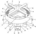
Fig. 1 is a schematic structural diagram of an embodiment of the present invention.
Fig. 2 is a front view of an embodiment of the present invention.
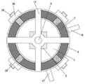
Fig. 3 is a top view of an embodiment of the present invention.
Fig. 4 is a cross-sectional view of an embodiment of the present invention.
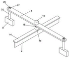
Fig. 5 is a schematic structural view of the cross plate according to the embodiment of the invention.
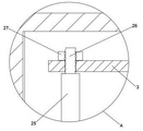
Fig. 6 is an enlarged schematic view of the invention at a in fig. 4.
Fig. 7 is an enlarged view of the structure of fig. 4 at B according to the present invention.
In the figure: 1. an air floatation tank; 2. an air flotation machine; 3. a transverse plate; 4. pushing the plate; 5. a housing; 6. an overflow cavity; 7. filtering the plate; 8. a squeegee; 9. a motor; 10. a connecting shaft; 11. a support frame; 12. a circulation pump; 13. a circulation pipe; 14. mounting a plate; 15. a threaded barrel; 16. a threaded rod; 17. a water inlet pipe; 18. a water outlet pipe; 19. an impurity removal pipe; 20. an impurity removal box; 21. a collection box; 22. a sealing cover; 23. a grip; 24. a support plate; 25. a support shaft; 26. a screw rod; 27. and (5) tightening the nut.
Detailed Description
The following further describes embodiments of the present invention with reference to the drawings.
As shown in fig. 1 to 7, an air-flotation sewage treatment device based on ultramicro nano bubbles comprises: cylindric air supporting pond 1, the inside in air supporting pond 1 is provided with air supporting machine 2, be provided with diaphragm 3 directly over air supporting pond 1, one side of diaphragm 3 is provided with and is used for driving its air supporting pond 1 circumferencial direction pivoted actuating mechanism, the bottom of diaphragm 3 is provided with the push pedal 4 that is located air supporting pond 1 top, and the bottom of push pedal 4 extends to the inside in air supporting pond 1, the outer wall fixed mounting in air supporting pond 1 has the casing 5 of reloading, be provided with overflow chamber 6 between casing 5 and the air supporting pond 1, the inside in overflow chamber 6 is provided with and is used for filterable filter plate 7 of impurity, the both ends of diaphragm 3 all are provided with the scraper blade 8 that is located overflow chamber 6 inside, and the diapire of scraper blade 8 hugs closely 7 and sets up the filter plate, be provided with the conveyor means who is used for the sewage backward flow between casing 5 and the air supporting pond 1.
In the embodiment, sewage is continuously added into the air flotation tank 1, the sewage gradually overflows from the top of the air flotation tank 1 and enters the overflow cavity 6, then the sewage is treated by the air flotation machine 2, impurities in the sewage are floated out of the inside of the sewage to a position above the liquid level, the overflowing sewage enters the inside of the overflow cavity 6, the transverse plate 3 is driven to rotate by the driving mechanism, the push plate 4 rotates at the top of the air flotation tank 1 along with the rotating transverse plate 3, the floated impurities are pushed to move, the impurities are accelerated to enter the inside of the overflow cavity 6 along with the sewage, the impurities are filtered by the filter plate 7, the sewage flows back into the inside of the air flotation tank 1 through the conveying part for repeated treatment, the impurities are left in the overflow cavity 6, the scraper 8 is driven to move in the overflow cavity 6 through the rotating transverse plate 3, the impurities at the top of the filter plate 7 are scraped, and the impurities are pushed to move, concentrate impurity, avoid impurity to block up filter plate 7, make that sewage can be better get into air supporting pond 1 through filter plate 7 backward flow, make equipment better when handling sewage, can be quick clear up the impurity that floats out, reduce staff's intensity of labour to can effectually avoid impurity to pile up the processing that influences bottom sewage in a large number in sewage liquid level top, thereby better improve equipment is to the treatment effect of sewage, facilitate for the user.
Specifically, actuating mechanism includes motor 9, and motor 9's output fixedly connected with connecting axle 10, and the bottom fixed connection of connecting axle 10 is at the middle part of diaphragm 3, drives connecting axle 10 through motor 9 and rotates, makes the better drive diaphragm 3 of connecting axle 10 rotate.
Further, the top fixedly connected with support frame 11 of casing 5, motor 9 fixed mounting are at support frame 11 top, through the setting of support frame 11, can be better support motor 9.
Specifically, the conveying part comprises a circulating pump 12 arranged on one side of the air floatation tank 1, a circulating pipe 13 inserted into the bottom of the shell 5 is arranged on one side of the circulating pump 12, and sewage entering the overflow cavity 6 is pumped out by the circulating pipe 13 through the circulating pump 12 and conveyed to the inside of the air floatation tank 1.
Preferably, the top fixedly connected with mounting panel 14 of push pedal 4, the top fixed mounting of backup pad 14 has a screw thread section of thick bamboo 15, the bottom fixedly connected with threaded connection of diaphragm 3 is at the inside threaded rod 16 of a screw thread section of thick bamboo 15, through mounting panel 14, the setting of a screw thread section of thick bamboo 15 and threaded rod 16, make threaded rod 16 rotate at a screw thread section of thick bamboo 15 inside through rotating mounting panel 14, and go up and down along a screw thread section of thick bamboo 15, can be better highly adjust push pedal 4, the change gets into the degree of depth in the air supporting pond 1 to push pedal 4, thereby the impurity that better promotion floated removes, accelerate the clearance of impurity.
Specifically, the lateral wall of air supporting pond 1 is pegged graft respectively and is had inlet tube 17 and outlet pipe 18, and inlet tube 17 and outlet pipe 18's inside all is provided with the valve, through the setting of inlet tube 17's outlet pipe 18, can be better carry out the injection of sewage and discharge to the inside of air supporting pond 1.
Preferably, the inside of casing 5 is provided with the edulcoration pipe 19 that is located filter plate 7 one side, the bottom of edulcoration pipe 19 is provided with edulcoration case 20, the inside sliding connection of edulcoration case 20 has collection box 21, through edulcoration pipe 19, edulcoration case 20, collect the setting of box 21 and sealed lid 22, by sealed lid 22 better when sewage treatment seal edulcoration pipe 19, avoid sewage to get into edulcoration pipe 19, and when overflow chamber 6 inside impurity is more, open sealed lid 22 and make the mouth of pipe of edulcoration pipe 19 open, make scraper blade 8 when promoting impurity removal, impurity can drop the inside that gets into edulcoration case 20 by edulcoration pipe 19, collect impurity by collecting box 21, can be better discharge and collect the inside impurity in overflow chamber 6, avoid impurity to pile up in a large amount in overflow chamber 6 inside, be convenient for the regular cleaning of impurity.
Further, the top of edulcoration pipe 19 is provided with sealed lid 22, collects the lateral wall fixedly connected with handle 23 of box 21, and through sealed lid 22, can be better seal edulcoration pipe 19, collect box 21 through the pulling that handle 23 can be better and take it out by edulcoration case 20 is inside.
Specifically, the inner wall of the housing 5 is fixedly connected with a support plate 24 positioned at the bottom of the filter plate 7, and the filter plate 7 is preferably supported in the middle of the overflow chamber 6 through the support plate 24, so that impurities are preferably filtered.
Preferably, the top fixedly connected with back shaft 25 of scraper blade 8, the top fixedly connected with of back shaft 25 pegs graft at the inside lead screw 26 of diaphragm 3, the outside threaded connection of lead screw 26 has the fastening nut 27 that is located the top of diaphragm 3, through the setting of back shaft 25, lead screw 26 and fastening nut 27, fastening nut 27 is taken off in the rotation, the lead screw 26 on back shaft 25 top is taken out by the inside of diaphragm 3, can be better dismantle scraper blade 8, can reach better washing or change scraper blade 8, also can be better take out filter plate 7 by the inside of overflow chamber 6, change filter plate 7, make it keep better filter effect.
In the description of the present invention, unless otherwise expressly specified or limited, the terms "mounted," "connected," and "connected" are to be construed broadly, e.g., as meaning a fixed connection, a removable connection, or an integral connection; can be mechanically or electrically connected; they may be connected directly or indirectly through intervening media, or they may be interconnected between two elements. The specific meanings of the above terms in the present invention can be understood in specific cases to those skilled in the art.
It will be evident to those skilled in the art that the invention is not limited to the details of the foregoing illustrative embodiments, and that the present invention may be embodied in other specific forms without departing from the spirit or essential attributes thereof. The present embodiments are therefore to be considered in all respects as illustrative and not restrictive, the scope of the invention being indicated by the appended claims rather than by the foregoing description, and all changes which come within the meaning and range of equivalency of the claims are therefore intended to be embraced therein. Any reference sign in a claim should not be construed as limiting the claim concerned.
Furthermore, it should be understood that although the present description refers to embodiments, not every embodiment may contain only a single embodiment, and such description is for clarity only, and those skilled in the art should integrate the description, and the embodiments may be combined as appropriate to form other embodiments understood by those skilled in the art.
Claims (10)
1. An air-flotation sewage treatment device based on ultramicro nano bubbles comprises: the air flotation device comprises a cylindrical air flotation tank (1), wherein an air flotation machine (2) is arranged inside the air flotation tank (1), and the air flotation device is characterized in that a transverse plate (3) is arranged right above the air flotation tank (1), a driving mechanism for driving the air flotation tank (1) to rotate in the circumferential direction is arranged on one side of the transverse plate (3), a push plate (4) positioned at the top of the air flotation tank (1) is arranged at the bottom of the transverse plate (3), the bottom of the push plate (4) extends into the air flotation tank (1), a replaceable shell (5) is fixedly arranged on the outer wall of the air flotation tank (1), an overflow cavity (6) is arranged between the shell (5) and the air flotation tank (1), a filter plate (7) for filtering impurities is arranged inside the overflow cavity (6), and scraping plates (8) positioned inside the overflow cavity (6) are arranged at two ends of the transverse plate (3), and the bottom wall of the scraper (8) is tightly attached to the filter plate (7), and a conveying part for sewage backflow is arranged between the shell (5) and the air floatation tank (1).
2. The air-flotation sewage treatment device based on ultramicro nanobubbles according to claim 1, wherein the driving mechanism comprises a motor (9), the output end of the motor (9) is fixedly connected with a connecting shaft (10), and the bottom end of the connecting shaft (10) is fixedly connected with the middle part of the transverse plate (3).
3. The air-flotation sewage treatment device based on the ultramicro-nanobubbles according to claim 2 is characterized in that a support frame (11) is fixedly connected to the top of the shell (5), and the motor (9) is fixedly installed on the top of the support frame (11).
4. The air-flotation sewage treatment device based on ultramicro nanobubbles according to claim 1, wherein the conveying means comprises a circulating pump (12) arranged at one side of the air-flotation tank (1), and a circulating pipe (13) inserted at the bottom of the housing (5) is arranged at one side of the circulating pump (12).
5. The air-flotation sewage treatment device based on ultramicro nanobubbles according to claim 1, wherein the top of the push plate (4) is fixedly connected with a mounting plate (14), the top of the support plate (14) is fixedly provided with a threaded cylinder (15), and the bottom of the transverse plate (3) is fixedly connected with a threaded rod (16) which is in threaded connection with the inside of the threaded cylinder (15).
6. The air-flotation sewage treatment device based on ultramicro nanobubbles according to claim 1, wherein the side wall of the air-flotation tank (1) is respectively inserted with a water inlet pipe (17) and a water outlet pipe (18), and valves are arranged inside the water inlet pipe (17) and the water outlet pipe (18).
7. The air-flotation sewage treatment device based on ultramicro nanobubbles according to claim 1, wherein the housing (5) is internally provided with an impurity removal pipe (19) at one side of the filter plate (7), the bottom of the impurity removal pipe (19) is provided with an impurity removal box (20), and the impurity removal box (20) is internally connected with a collection box (21) in a sliding manner.
8. The air-flotation sewage treatment device based on ultramicro nanobubbles according to claim 7 is characterized in that the top end of the impurity removal pipe (19) is provided with a sealing cover (22), and the side wall of the collection box (21) is fixedly connected with a handle (23).
9. The air-flotation sewage treatment device based on ultramicro nanobubbles according to claim 1 is characterized in that the inner wall of the shell (5) is fixedly connected with a support plate (24) positioned at the bottom of the filter plate (7).
10. The air-flotation sewage treatment device based on ultramicro nanobubbles according to claim 1, wherein the top of the scraping plate (8) is fixedly connected with a supporting shaft (25), the top end of the supporting shaft (25) is fixedly connected with a screw rod (26) inserted inside the transverse plate (3), and the external thread of the screw rod (26) is connected with a fastening nut (27) positioned at the top of the transverse plate (3).
Priority Applications (1)
| Application Number | Priority Date | Filing Date | Title |
|---|---|---|---|
| CN202210607714.3A CN114853198A (en) | 2022-05-31 | 2022-05-31 | Air-flotation sewage treatment device based on ultramicro nano bubbles |
Applications Claiming Priority (1)
| Application Number | Priority Date | Filing Date | Title |
|---|---|---|---|
| CN202210607714.3A CN114853198A (en) | 2022-05-31 | 2022-05-31 | Air-flotation sewage treatment device based on ultramicro nano bubbles |
Publications (1)
| Publication Number | Publication Date |
|---|---|
| CN114853198A true CN114853198A (en) | 2022-08-05 |
Family
ID=82640350
Family Applications (1)
| Application Number | Title | Priority Date | Filing Date |
|---|---|---|---|
| CN202210607714.3A Pending CN114853198A (en) | 2022-05-31 | 2022-05-31 | Air-flotation sewage treatment device based on ultramicro nano bubbles |
Country Status (1)
| Country | Link |
|---|---|
| CN (1) | CN114853198A (en) |
Citations (6)
| Publication number | Priority date | Publication date | Assignee | Title |
|---|---|---|---|---|
| WO2013156002A1 (en) * | 2012-04-19 | 2013-10-24 | 波鹰(厦门)科技有限公司 | Nano catalyst electrolysis flocculation air flotation device |
| CN209651932U (en) * | 2019-01-11 | 2019-11-19 | 周家永 | A kind of circulating water-saving air floatation machine |
| CN213171561U (en) * | 2020-08-28 | 2021-05-11 | 海口达清环保科技有限公司 | Small-size air supporting device |
| CN213707799U (en) * | 2020-10-30 | 2021-07-16 | 广东粤绿环境工程有限公司 | Scum treatment device of air floatation machine |
| CN113457244A (en) * | 2021-07-17 | 2021-10-01 | 庄碧青 | Sewage treatment device |
| CN214400128U (en) * | 2020-11-12 | 2021-10-15 | 江苏金信环境工程有限公司 | Sewage depths processing apparatus convenient to clearance filter screen |
-
2022
- 2022-05-31 CN CN202210607714.3A patent/CN114853198A/en active Pending
Patent Citations (6)
| Publication number | Priority date | Publication date | Assignee | Title |
|---|---|---|---|---|
| WO2013156002A1 (en) * | 2012-04-19 | 2013-10-24 | 波鹰(厦门)科技有限公司 | Nano catalyst electrolysis flocculation air flotation device |
| CN209651932U (en) * | 2019-01-11 | 2019-11-19 | 周家永 | A kind of circulating water-saving air floatation machine |
| CN213171561U (en) * | 2020-08-28 | 2021-05-11 | 海口达清环保科技有限公司 | Small-size air supporting device |
| CN213707799U (en) * | 2020-10-30 | 2021-07-16 | 广东粤绿环境工程有限公司 | Scum treatment device of air floatation machine |
| CN214400128U (en) * | 2020-11-12 | 2021-10-15 | 江苏金信环境工程有限公司 | Sewage depths processing apparatus convenient to clearance filter screen |
| CN113457244A (en) * | 2021-07-17 | 2021-10-01 | 庄碧青 | Sewage treatment device |
Similar Documents
| Publication | Publication Date | Title |
|---|---|---|
| CN201046362Y (en) | Full-automatic effluent purification machine | |
| CN212609954U (en) | Environment-friendly sewage treatment plant | |
| CN111039458B (en) | Ecological prosthetic devices in plateau lake fishery waters | |
| CN114853198A (en) | Air-flotation sewage treatment device based on ultramicro nano bubbles | |
| CN217677122U (en) | Auxiliary sludge discharge device for industrial wastewater secondary sedimentation tank | |
| CN116036670A (en) | Water treatment sedimentation tank | |
| CN215828566U (en) | Integrated sewage treatment device | |
| CN215480428U (en) | Sewage recovery plant heating mechanism | |
| CN114751543A (en) | Net zero-discharge recovery equipment for electroplating wastewater and recovery method thereof | |
| CN220328012U (en) | Sedimentation tank for sewage treatment | |
| CN220695935U (en) | Advection sedimentation tank of high-efficient row mud | |
| CN214653723U (en) | Waste water treatment device of slag treatment plant | |
| CN219539519U (en) | Inclined plate sedimentation tank for battery disassembly | |
| CN218539380U (en) | Novel electrochemistry integration sled dress equipment | |
| CN212998566U (en) | Sludge discharge device for sewage treatment | |
| CN218709352U (en) | Sediment machine device is scraped in air supporting | |
| CN219848541U (en) | Industrial wastewater regulating tank | |
| CN214004278U (en) | Flocculation filtration purification's integration printing sewage treatment plant | |
| CN219297246U (en) | Just, with battery of adding flocculating agent disassembles and uses sewage precipitation case | |
| CN216920640U (en) | Hydraulic engineering is with stifled cistern that prevents that has purification performance | |
| CN215627161U (en) | Power plant wastewater treatment device | |
| CN217025674U (en) | Continuous flow A/O waste water treatment equipment | |
| CN218900939U (en) | Wastewater air floatation precipitation integrated sedimentation tank | |
| CN218620366U (en) | Disinfection equipment capable of preventing sewage from flowing backwards | |
| CN219409512U (en) | Water circulating device for fishery cultivation |
Legal Events
| Date | Code | Title | Description |
|---|---|---|---|
| PB01 | Publication | ||
| PB01 | Publication | ||
| SE01 | Entry into force of request for substantive examination | ||
| SE01 | Entry into force of request for substantive examination |