CN114850083A - Pushing piece wiping mechanism and pushing piece device - Google Patents
Pushing piece wiping mechanism and pushing piece device Download PDFInfo
- Publication number
- CN114850083A CN114850083A CN202110162450.0A CN202110162450A CN114850083A CN 114850083 A CN114850083 A CN 114850083A CN 202110162450 A CN202110162450 A CN 202110162450A CN 114850083 A CN114850083 A CN 114850083A
- Authority
- CN
- China
- Prior art keywords
- wiping
- piece
- push
- blade
- plate
- Prior art date
- Legal status (The legal status is an assumption and is not a legal conclusion. Google has not performed a legal analysis and makes no representation as to the accuracy of the status listed.)
- Granted
Links
- 230000007246 mechanism Effects 0.000 title claims abstract description 139
- 238000004804 winding Methods 0.000 claims description 81
- 238000004140 cleaning Methods 0.000 claims description 22
- 239000007788 liquid Substances 0.000 claims description 12
- 238000002347 injection Methods 0.000 claims description 8
- 239000007924 injection Substances 0.000 claims description 8
- 230000005540 biological transmission Effects 0.000 claims description 3
- 230000033001 locomotion Effects 0.000 abstract description 7
- 238000004506 ultrasonic cleaning Methods 0.000 abstract description 5
- 239000008280 blood Substances 0.000 description 28
- 210000004369 blood Anatomy 0.000 description 28
- 239000011521 glass Substances 0.000 description 24
- 239000000758 substrate Substances 0.000 description 13
- 230000003993 interaction Effects 0.000 description 10
- 230000000694 effects Effects 0.000 description 9
- 230000009471 action Effects 0.000 description 8
- 230000001939 inductive effect Effects 0.000 description 7
- 230000008878 coupling Effects 0.000 description 6
- 238000010168 coupling process Methods 0.000 description 6
- 238000005859 coupling reaction Methods 0.000 description 6
- 238000009434 installation Methods 0.000 description 6
- 238000003825 pressing Methods 0.000 description 5
- 238000010586 diagram Methods 0.000 description 4
- 230000001965 increasing effect Effects 0.000 description 3
- 206010011409 Cross infection Diseases 0.000 description 2
- 206010029803 Nosocomial infection Diseases 0.000 description 2
- 238000002360 preparation method Methods 0.000 description 2
- 230000037452 priming Effects 0.000 description 2
- 230000004044 response Effects 0.000 description 2
- 230000004308 accommodation Effects 0.000 description 1
- 230000003044 adaptive effect Effects 0.000 description 1
- 230000008859 change Effects 0.000 description 1
- 238000011109 contamination Methods 0.000 description 1
- 239000012530 fluid Substances 0.000 description 1
- 230000005484 gravity Effects 0.000 description 1
- 239000000463 material Substances 0.000 description 1
- 230000013011 mating Effects 0.000 description 1
- 238000000034 method Methods 0.000 description 1
- 230000004048 modification Effects 0.000 description 1
- 238000012986 modification Methods 0.000 description 1
- 230000000149 penetrating effect Effects 0.000 description 1
- 230000000452 restraining effect Effects 0.000 description 1
- 238000000926 separation method Methods 0.000 description 1
- 230000008054 signal transmission Effects 0.000 description 1
- 239000000243 solution Substances 0.000 description 1
- 239000012780 transparent material Substances 0.000 description 1
- 238000011144 upstream manufacturing Methods 0.000 description 1
Images


Classifications
-
- B08B1/143—
-
- B08B1/30—
-
- G—PHYSICS
- G01—MEASURING; TESTING
- G01N—INVESTIGATING OR ANALYSING MATERIALS BY DETERMINING THEIR CHEMICAL OR PHYSICAL PROPERTIES
- G01N1/00—Sampling; Preparing specimens for investigation
- G01N1/28—Preparing specimens for investigation including physical details of (bio-)chemical methods covered elsewhere, e.g. G01N33/50, C12Q
- G01N1/2813—Producing thin layers of samples on a substrate, e.g. smearing, spinning-on
Abstract
The invention relates to a push sheet wiping mechanism and a push sheet device, wherein a fixed seat is arranged on the push sheet wiping mechanism; the wiping unit is slidably arranged on the fixed seat, and a wiping piece for wiping a push sheet of the push sheet mechanism is arranged on the wiping unit; the second driving part is installed on the fixed seat and is configured to drive the wiping unit to reciprocate relative to the fixed seat so that the wiping part wipes the push sheet of the push sheet mechanism. Above-mentioned push jack wiping mechanism and push jack device, the unit of wiping drives the wiper and wipes the push jack of push jack mechanism for fixing base reciprocating motion, and for the condition of ultrasonic cleaning push jack among the prior art, the time spent is shorter.
Description
Technical Field
The invention relates to the technical field of medical instruments, in particular to a push sheet wiping mechanism and a push sheet device.
Background
When observing a tiny object, the tiny object is often required to be made into a microscope slide specimen so as to be observed under a microscope. The microscopic slide specimen comprises a slice, a loading piece and a smear, wherein the smear is a specimen which is prepared by uniformly smearing a liquid specimen (such as blood, marrow fluid and the like) collected from an organism on a glass slide, and is widely applied to the medical field.
For example, when examining a patient, it is sometimes necessary to test the blood of the patient. In this case, blood should be uniformly smeared on a slide glass to prepare a blood smear, and the prepared blood smear should be observed under a microscope. In order to avoid contamination of the sample by manual operation, a slide pushing mechanism is often used to push the drop of blood flat and uniformly spread the blood on the slide.
In order to avoid cross infection, after the push piece mechanism pushes blood once, the push piece of the push piece mechanism needs to be cleaned, ultrasonic cleaning is generally adopted, and the problem of long cleaning time exists in the ultrasonic cleaning.
Disclosure of Invention
Accordingly, it is necessary to provide a pusher wiping mechanism and a pusher device that are short in time, in order to solve the problem that the length of time required for cleaning the pusher is long.
A pusher wiping mechanism comprising:
a fixed seat;
the wiping unit is slidably arranged on the fixed seat, and a wiping piece for wiping a push sheet of the push sheet mechanism is arranged on the wiping unit;
the second driving part is installed on the fixed seat and is configured to drive the wiping unit to reciprocate relative to the fixed seat so that the wiping part wipes the push sheet of the push sheet mechanism.
In one embodiment, the wiping unit is provided with a wiping position, the wiping piece comprises a wiping strip, a plurality of wiping parts are formed on the wiping strip, and the wiping strip can move relative to the wiping unit to enable the plurality of wiping parts to be alternatively arranged in the wiping position;
wherein a moving direction of the wiping belt is perpendicular to a moving direction of the wiping unit.
In one embodiment, the wiping member further includes a tape cassette provided on the wiping unit, the wiping tape is provided in the tape cassette, a first winding member and a second winding member are provided in the tape cassette, one end of the wiping tape is connected to the first winding member, the other end of the wiping tape is connected to the second winding member, and the wiping tape is moved relative to the tape cassette by the first winding member and the second winding member.
In one embodiment, the blade-pushing wiping mechanism further comprises a third driving member, the third driving member comprises a driving shaft and a driven shaft, one of the first winding member and the second winding member is connected with the driving shaft, and the other of the first winding member and the second winding member is connected with the driven shaft.
In one embodiment, the wiping unit comprises a first connecting plate and a second connecting plate, the first connecting plate is connected with the fixed seat in a sliding mode, the second connecting plate is movably connected with the first connecting plate, and the tape box is arranged on the second connecting plate;
the second connecting plate can be switched between a first position and a second position relative to the first connecting plate, the third driving piece limits the tape cassette to the second connecting plate in the first position, and the third driving piece allows the tape cassette to be separated from the second connecting plate in the second position.
In one embodiment, the wiping unit further comprises a mounting piece movably connected with one of the first connecting plate and the second connecting plate, and a fitting piece connected with the other of the first connecting plate and the second connecting plate;
the fitting piece is movably connected with the mounting piece so as to be capable of being switched between a third position and a fourth position relative to the mounting piece, when the third position is reached, the fitting piece is matched with the mounting piece to limit the second connecting plate to the first position, and when the fourth position is reached, the fitting piece is matched with the mounting piece to limit the second connecting plate to the second position.
In one embodiment, the push sheet wiping mechanism further comprises a third inductive switch, a counting disc and a counting wheel, wherein the counting wheel is abutted with the wiping belt and rotates under the friction force of the wiping belt, the counting disc is in transmission connection with the counting wheel, and the third inductive switch is configured to sense the rotation angle of the counting disc.
In one embodiment, the push sheet wiping mechanism further comprises a first connecting rod and a second connecting rod, one end of the first connecting rod is fixedly connected with the second driving piece, the other end of the first connecting rod is hinged with one end of the second connecting rod, and the other end of the second connecting rod is hinged with the wiping unit.
In one embodiment, the push-piece wiping mechanism further comprises an injection member configured to inject a cleaning medium onto the wiper member or the push-piece.
A blade pushing device comprises a blade pushing mechanism and a blade pushing wiping mechanism, wherein the blade pushing mechanism comprises a blade pushing piece, and the blade pushing piece can be switched between a blade pushing position and a cleaning position.
Above-mentioned push jack wiping mechanism and push jack device, the unit of wiping drives the wiper and wipes the push jack of push jack mechanism for fixing base reciprocating motion, and for the condition of ultrasonic cleaning push jack among the prior art, the time spent is shorter.
Drawings
FIG. 1 is an isometric view of a blade pushing device provided in accordance with an embodiment of the present invention;
FIG. 2 is an isometric view from a perspective of a slide mechanism of the slide pushing device shown in FIG. 1;
FIG. 3 is an isometric view of another perspective of the slide mechanism shown in FIG. 2;
FIG. 4 is an isometric view from a perspective of a blade pushing mechanism of the blade pushing device shown in FIG. 1;
FIG. 5 is an isometric view of the blade pushing mechanism shown in FIG. 4 from another perspective;
FIG. 6 is a plan view of the pusher member of the pusher assembly shown in FIG. 1 in a pusher position;
FIG. 7 is an isometric view of yet another perspective of the blade pushing mechanism shown in FIG. 4;
FIG. 8 is a partial cross-sectional view of the blade pushing mechanism shown in FIG. 4;
FIG. 9 is a partial block diagram of the blade pushing mechanism shown in FIG. 4;
FIG. 10 is a block diagram of a first body of a mounting block of the blade pushing mechanism shown in FIG. 4;
FIG. 11 is a plan view of the blade pushing device shown in FIG. 1 in a cleaning position;
FIG. 12 is a perspective view of a blade wiping mechanism of the blade pushing device shown in FIG. 1;
FIG. 13 is a block diagram of a wiper of the pusher wiper mechanism shown in FIG. 12;
FIG. 14 is an isometric view of another perspective of the blade wiping mechanism shown in FIG. 12;
FIG. 15 is a partial structural block diagram of the wipe shown in FIG. 13;
FIG. 16 is an isometric view of a partial structure of the wipe shown in FIG. 15;
FIG. 17 is an isometric view of yet another perspective of the push-tab wiping mechanism shown in FIG. 12;
FIG. 18 is an isometric view of yet another perspective of the blade wiping mechanism shown in FIG. 12;
FIG. 19 is an isometric view of the second web of the push-tab wiping mechanism shown in FIG. 12 in a first position;
FIG. 20 is an isometric view of the second web of the push-tab wiping mechanism shown in FIG. 12 in a second position;
FIG. 21 is a view showing the structure of the blade wiping mechanism shown in FIG. 1 when the wiping belt abuts against the blade;
FIG. 22 is an isometric view of the locating block and resilient member of the wiper member shown in FIG. 13;
fig. 23 is a structural view of a second housing half of the cartridge of the wiper shown in fig. 13.
100. A blade pushing device; 10. a blade-pushing wiping mechanism; 11. a fixed seat; 12. a wiping unit; 122. an accommodating chamber; 123. a first connecting plate; 124. a second connecting plate; 125. mounting a sheet; 1251. a limiting groove; 126. a mating member; 13. a wiper; 131. wiping the tape; 1311. a wiping section; 132. a tape cassette; 1321. a first opening; 1322. a second opening; 1323. an observation window; 1324. a first half shell; 1325. a second half shell; 133. positioning blocks; 1331. a right angle portion; 134. an elastic element; 1341. a first abutment plane; 1342. a second abutment plane; 135. a first winding member; 136. a second winding member; 137. tabletting; 1381. a first sub-limiting member; 1382. a second sub-limiting member; 1391. a first tape guide; 1392. a second tape guide; 1393. a third tape guide; 14. a second driving member; 141. a second drive motor; 15. a third slide rail; 16. a third slider; 17. a second inductive switch; 18. a second sensing piece; 191. a first link; 192. a second link; 110. injecting liquid; 120. a third driving member; 130. a third drive motor; 140. a driven shaft; 150. a drive shaft; 1120. a counting wheel; 1130. a counting disc; 1140. a third inductive switch; 20. a blade pushing mechanism; 21. a mounting base; 211. a first mounting plate; 212. a second mounting plate; 22. rotating the block; 23. a first driving member; 231. a first drive motor; 232. a coupling; 24. mounting blocks; 241. a first body; 2411. a first body; 2412. a second sub-body; 242. a clamping piece; 25. pushing the sheet; 26. a first elastic member; 261. a first sub-elastic member; 262. a second sub-elastic member; 27. a first rotating shaft; 28. a second rotating shaft; 29. a second elastic member; 210. a second slide rail; 220. a second slider; 230. a guide member; 240. a first connection portion; 250. a limiting part; 260. a first inductive switch; 270. a first sensing piece; 30. a slide mechanism; 31. a fixing plate; 32. a drive assembly; 321. a fourth drive motor; 322. a driving wheel; 323. a belt; 324. a driven wheel; 325. a screw rod; 33. a slide mount; 331. a base plate; 3311. taking the groove; 332. a first limit plate; 333. a second limiting plate; 34. a first slide rail; 35. a first slider; 40. a substrate; 41. a through hole; 200. a slide.
Detailed Description
In order to make the aforementioned objects, features and advantages of the present invention comprehensible, embodiments accompanied with figures are described in detail below. In the following description, numerous specific details are set forth in order to provide a thorough understanding of the present invention. This invention may, however, be embodied in many different forms and should not be construed as limited to the embodiments set forth herein.
In the description of the present invention, it is to be understood that the terms "central," "longitudinal," "lateral," "length," "width," "thickness," "upper," "lower," "front," "rear," "left," "right," "vertical," "horizontal," "top," "bottom," "inner," "outer," "clockwise," "counterclockwise," "axial," "radial," "circumferential," and the like are used in the orientations and positional relationships indicated in the drawings for convenience in describing the invention and to simplify the description, and are not intended to indicate or imply that the referenced device or element must have a particular orientation, be constructed and operated in a particular orientation, and are not to be considered limiting of the invention.
Furthermore, the terms "first", "second" and "first" are used for descriptive purposes only and are not to be construed as indicating or implying relative importance or implicitly indicating the number of technical features indicated. Thus, a feature defined as "first" or "second" may explicitly or implicitly include at least one such feature. In the description of the present invention, "a plurality" means at least two, e.g., two, three, etc., unless specifically limited otherwise.
In the present invention, unless otherwise expressly stated or limited, the terms "mounted," "connected," "secured," and the like are to be construed broadly and can, for example, be fixedly connected, detachably connected, or integrally formed; can be mechanically or electrically connected; they may be directly connected or indirectly connected through intervening media, or they may be connected internally or in any other suitable relationship, unless expressly stated otherwise. The specific meanings of the above terms in the present invention can be understood by those skilled in the art according to specific situations.
In the present invention, unless otherwise expressly stated or limited, the first feature "on" or "under" the second feature may be directly contacting the first and second features or indirectly contacting the first and second features through an intermediate. Also, a first feature "on," "over," and "above" a second feature may be directly or diagonally above the second feature, or may simply indicate that the first feature is at a higher level than the second feature. A first feature being "under," "below," and "beneath" a second feature may be directly under or obliquely under the first feature, or may simply mean that the first feature is at a lesser elevation than the second feature.
It will be understood that when an element is referred to as being "secured to" or "disposed on" another element, it can be directly on the other element or intervening elements may also be present. When an element is referred to as being "connected" to another element, it can be directly connected to the other element or intervening elements may also be present. The terms "vertical," "horizontal," "upper," "lower," "left," "right," and the like as used herein are for illustrative purposes only and do not denote a unique embodiment.
Referring to fig. 1, an embodiment of the present invention provides a slide pushing device 100 capable of pushing a droplet of liquid to be flat on a slide 200. Specifically, the push sheet device 100 is applied to a fully automatic blood push sheet preparation instrument, and can push and level drop-shaped blood to be sheet-shaped on a slide glass 200 to prepare a blood smear. It should be understood that, in other embodiments, the slide pushing device 100 may also be applied to other apparatuses for preparing other types of slide specimens, which is not limited herein.
The following describes the technical solution of the present application in detail, taking the application of the push sheet device 100 to a full-automatic blood push sheet preparation apparatus as an example. The present embodiment is only for exemplary purposes and does not limit the technical scope of the present application. In addition, the drawings in the embodiments omit unnecessary components to clearly show the technical features of the application.
The slide pushing device 100 comprises a slide pushing and wiping mechanism 10, a slide pushing mechanism 20 and a slide loading mechanism 30, wherein the slide loading mechanism 30 is used for bearing the slide 200, the slide pushing mechanism 20 is used for pushing flat the blood drop-shaped on the slide 200, and the slide pushing and wiping mechanism 10 is used for wiping the push piece 25 of the slide pushing mechanism 20 so as to clean the push piece 25. In other embodiments, the slide mechanism 30 may be omitted from the blade pushing device 100, and is not limited herein.
In one embodiment, the blade pushing device 100 further includes a base plate 40, and the blade pushing wiping mechanism 10, the blade pushing mechanism 20 and the blade carrying mechanism 30 are disposed on the base plate 40, and the base plate 40 is a base for mounting the blade pushing wiping mechanism 10, the blade pushing mechanism 20 and the blade carrying mechanism 30. Specifically, the slide mechanism 30 is disposed below the substrate 40, and the blade pushing mechanism 20 and the blade pushing wiping mechanism 10 are disposed above the substrate 40. Meanwhile, the base plate 40 is provided with a through hole 41 in a penetrating manner along the thickness direction, and the sheet pushing mechanism 20 is communicated with the slide mechanism 30 through the through hole 41, so that the sheet pushing mechanism 20 pushes the blood on the slide 200. More specifically, at least a portion of the slide mechanism 30 extends into the through hole 41 such that the upper surface of the slide 200 is flush with the upper surface of the base plate 40 when the slide 200 is placed on the slide mechanism 30. Of course, in other embodiments, the entire slide mechanism 30 and the slide 200 may not protrude from the lower surface of the base plate 40, and when the push mechanism 20 pushes the blood on the slide 200, the push piece 25 needs to extend into the through hole 41 to push the blood.
It is contemplated that in other embodiments, the base plate 40 may be omitted from the blade pushing device 100, and the blade pushing mechanism 20 and the blade wiping mechanism 10 may be directly connected to the slide mechanism 30.
In one embodiment, the pushing mechanism 20 is fixed relative to the base plate 40, and the slide mechanism 30 pushes the slide 200 to move relative to the base plate 40, at which time the slide 200 moves relative to the pushing mechanism 20, so as to achieve the effect of pushing blood flat. Of course, in other embodiments, slide 200 may be stationary and blade pushing mechanism 20 may be moved relative to base plate 40 to achieve the effect of flattening the blood.
Referring to fig. 2, the slide mechanism 30 includes a fixing plate 31, a driving assembly 32 and a slide holder 33, the fixing plate 31 is fixedly connected to the base plate 40, the slide holder 33 is slidably connected to the fixing plate 31, and the driving assembly 32 is connected to the base plate 40 and/or the fixing plate 31 for driving the slide holder 33 to reciprocate in a third direction relative to the fixing plate 31. When the driving assembly 32 drives the slide holder 33 to move forward in the third direction relative to the fixing plate 31, the push piece 25 of the push piece mechanism 20 can push the blood on the slide 200 placed on the slide holder 33 to be flat, and when the driving assembly drives the slide holder 33 to move backward in the third direction, the slide holder 33 can return to the initial position, so that the next blood smear can be made.
Referring to fig. 3, the driving assembly 32 includes a fourth driving motor 321, a driving wheel 322, a belt 323, a driven wheel 324 and a screw rod 325, the fourth driving motor 321 is connected to the fixing plate 31, the driving wheel 322 is connected to a driving end of the fourth driving motor 321, the screw rod 325 is connected to the fixing plate 31, the driven wheel 324 is connected to an extending end of the screw rod 325 extending out of the fixing plate 31, and the belt 323 is sleeved outside the driving wheel 322 and the driven wheel 324. The slide holder 33 is screwed to the screw rod 325 and is slidably engaged with the fixing plate 31. Thus, when the fourth driving motor 321 rotates forward, the driving wheel 322 is driven to rotate, the belt 323 drives the driven wheel 324 to rotate, the screw rod 325 rotates forward, the slide holder 33 drives the slide 200 to move forward in the third direction, and the push piece 25 of the push piece mechanism 20 pushes the blood on the slide 200 flat. When the fourth driving motor 321 rotates reversely, the driving wheel 322 is driven to rotate, the belt 323 drives the driven wheel 324 to rotate, the screw rod 325 rotates reversely, and the slide holder 33 moves reversely in the third direction to return to the initial position, so that the next blood smear can be produced.
It is contemplated that in other embodiments, the drive assembly 32 can be arranged to drive the slide mount 33 in a reciprocating motion relative to the stationary plate 31.
The slide mechanism 30 further includes a first slide rail 34 and a first slide block 35, one of the first slide rail 34 and the first slide block 35 is fixedly connected to the fixing plate 31, the other is fixedly connected to the slide holder 33, and the slide holder 33 is slidably fitted to the fixing plate 31 through the first slide block 35 and the first slide rail 34. In this embodiment, the first slide rail 34 is connected to the fixing plate 31, the first slide block 35 is connected to the slide holder 33, and the slide holder 33 is connected to the screw 325 by the first slide block 35.
The slide holder 33 includes a bottom plate 331, a first stopper plate 332, and a second stopper plate 333, the bottom plate 331 is screwed to the screw rod 325, and the slide 200 is disposed on the bottom plate 331. The first limiting plate 332 and the second limiting plate 333 are connected to the upper surface of the bottom plate 331 and extend towards a direction away from the bottom plate 331, and in a third direction, the first limiting plate 332 and the second limiting plate 333 are located at two ends of the bottom plate 331 respectively, and two ends of the slide 200 are abutted to the first limiting plate 332 and the second limiting plate 333 respectively. The distance between the first and second stopper plates 332, 333 determines the length of the slide 200, i.e., the second and second stopper plates 333, 333 are positioned to limit the length of the slide 200.
In a second direction perpendicular to the third direction, i.e., perpendicular to the connecting line of the first and second limiting plates 332, 333, the two sides of the bottom plate 331 are recessed with a taking groove 3311, so that when a slide 200 is placed on the slide holder 33, a human hand can extend into the taking groove 3311, thereby facilitating the placement of the slide 200 on the slide holder 33, and when the slide 200 on the slide holder 33 needs to be taken down, the human hand can also extend into the taking groove 3311, thereby facilitating the removal of the slide 200 placed on the slide holder 33. Thus, by providing the taking grooves 3311, it is possible to facilitate taking and placing the slide glass 200 in the width direction of the slide glass 200.
Referring to fig. 4, in an embodiment, the blade pushing mechanism 20 includes a mounting base 21, a rotating block 22 and a first driving member 23, the mounting base 21 is mounted on the substrate 40, the rotating block 22 and the first driving member 23 are both mounted on the mounting base 21, the rotating block 22 is pivotally connected to the mounting base 21, and the first driving member 23 is configured to drive the rotating block 22 to rotate around a first axis relative to the mounting base 21.
Referring to fig. 5, the pushing piece mechanism 20 further includes a mounting block 24 for mounting the pushing piece 25, when the first driving member 23 drives the rotating block 22 to rotate around the first axis relative to the mounting base 21, the rotating block 22 drives the mounting block 24 to rotate, so that the pushing piece 25 mounted on the mounting block 24 can be in the pushing piece position (see fig. 6), i.e., the inclination angle between the pushing piece 25 and the slide glass 200 can be in the range of 0 ° to 90 °. In the slide-pushing position, the slide-pushing piece 200 can contact with the slide, and when the slide-pushing piece 200 and the slide are relatively moved, the slide-pushing piece 200 can push the liquid (such as blood) in a drop shape to be flat so as to make a slide specimen.
Specifically, the mounting block 24 is movably connected to the rotating block 22, referring to fig. 7, the blade pushing mechanism 20 further includes a first elastic member 26, the first elastic member 26 is abutted between the rotating block 22 and the mounting block 24, and the mounting block 24 can swing relative to the rotating block 22. Through the arrangement, when the push piece 25 is in contact with the slide glass 200, an interaction force is generated between the slide glass 200 and the push piece 25, the push piece 25 transmits the interaction force to the mounting block 24, the mounting block 24 compresses the first elastic piece 26, and the mounting block 24 and the push piece 25 are under the action of the elastic restoring force of the first elastic piece 26, so that the push piece 25 is tightly attached to each part of the slide glass 200. Namely, by arranging the first elastic member 26 and movably connecting the mounting block 24 with the rotating block 22, when the mounting position of the push piece 25 is not accurate or the slide glass 200 is not placed normally, the push piece mechanism 20 can be adjusted adaptively according to the change of the working condition to ensure that the push piece 25 is tightly attached to each part of the slide glass 200, so that blood is pushed flat, and the adaptive effect of the push piece mechanism 20 is good.
Specifically, the first elastic element 26 abuts between the mounting block 24 and the rotating block 22 in a first direction, and the first direction intersects with the extending direction of the first axis. It should be noted that the first direction intersecting the extending direction of the first axis means: the first direction and the extension direction of the first axis lie in the same plane in which the first direction and the extension direction of the first axis intersect, or the first direction and the extension direction of the first axis can intersect in a three-dimensional space.
It should be noted that the above-mentioned pushing piece position is not the only fixed position, and can be selected according to the requirement as long as the inclined angle between the pushing piece 25 and the slide glass 200 is ensured to be in the range of 0-90 °.
According to the reference standard of fig. 1, the first direction is a vertical direction, the second direction is a connecting line direction between a lower left corner and an upper right corner, the third direction is a connecting line direction between an upper left corner and a lower right corner, the first direction, the second direction and the third direction are perpendicular to each other in pairs, that is, the first direction is a Z direction in fig. 1, the second direction is a Y direction in fig. 1, and the third direction is an X direction in fig. 1.
With reference to fig. 4, the first driving member 23 includes a first driving motor 231 and a coupling 232, and the first driving motor 231 is fixedly connected to the rotating block 22 through the coupling 232. The blade pushing mechanism 20 further includes two first rotating shafts 27 (see fig. 7), the two first rotating shafts 27 are respectively fixedly connected to two ends of the rotating block 22, one of the first rotating shafts 27 is disposed in the mounting base 21 and fixedly connected to the first driving motor 231 through the coupling 232, and the other first rotating shaft 27 is disposed in the fixing base 11 and rotatably connected thereto. First driving motor 231 drives first pivot 27 through shaft coupling 232 and rotates, and first pivot 27 drives turning block 22 and rotates for mount pad 21, and first axis is the axis of first pivot 27.
Further, the mounting block 24 is configured to be rotatable relative to the rotating block 22 about a second axis whose extending direction intersects with the extending direction of the first axis in the same plane or in a three-dimensional space.
With reference to fig. 7 and 8, the first elastic element 26 includes a first sub-elastic element 261 and a second sub-elastic element 262, and the first sub-elastic element 261 and the second sub-elastic element 262 are distributed on two sides of the second axis in the extending direction of the first axis. Thus, when the push piece 25 contacts with the slide glass 200, an interaction force is generated between the slide glass 200 and the push piece 25, the push piece 25 transmits the action force to the mounting block 24, the mounting block 24 transmits the action force to the first sub-elastic member 261 and/or the second sub-elastic member 262, and the first sub-elastic member 261 and/or the second sub-elastic member 262 elastically deforms under the force of the force, so as to further ensure the close fit between the push piece 25 and the slide glass 200, thereby ensuring the flattening effect of blood.
Specifically, the first sub elastic member 261 and the second sub elastic member 262 are both springs, at least one of the mounting block 24 and the rotating block 22 is provided with a mounting hole, and portions of the first sub elastic member 261 and the second sub elastic member 262 are disposed in the mounting hole. More specifically, the mounting block 24 and the rotating block 22 are both provided with mounting holes, and both ends of the first sub elastic member 261 and the second sub elastic member 262 are respectively provided in the corresponding mounting holes. Of course, in other embodiments, the first sub-elastic member 261 and the second sub-elastic member 262 may be made of rubber, and are not limited herein.
Referring to fig. 4 and 9, the blade pushing mechanism 20 includes a second rotating shaft 28, the rotating block 22 is L-shaped, one end of the mounting block 24 is disposed at the right-angled groove of the L-shape, the first elastic element 26 is disposed between one end of the L-shape and the mounting block 24, and the second rotating shaft 28 is connected to the other end of the L-shape. One end of the L-shaped structure is provided with a rotating shaft hole, the second rotating shaft 28 penetrates through the rotating shaft hole to realize the rotating connection of the mounting block 24 and the rotating block 22, and the second axis is the central axis of the second rotating shaft 28.
In one embodiment, the blade pushing mechanism 20 further comprises a blade 25, and the blade 25 is mounted on the mounting block 24. Specifically, the push plate 25 is detachably connected to the mounting block 24 to facilitate replacement of the push plate 25. It is contemplated that in other embodiments, the push plate 25 may be integrally formed with the mounting block 24, and is not limited thereto.
Referring to fig. 9, the mounting block 24 includes a first body 241 and a clamping piece 242, the first body 241 is rotatably connected to the rotating block 22, the first elastic element 26 is abutted between the first body 241 and the rotating block 22 in the first direction, and the clamping piece 242 is mounted on the first body 241. A clamping opening is formed between the clamping piece 242 and the first body 241, the pushing piece 25 is pressed between the clamping piece 242 and the first body 241 from the clamping opening, and the clamping piece 242 has elasticity. Since the clamping piece 242 has elasticity, when the push piece 25 is mounted on the mounting block 24, the clamping piece 242 is broken to be elastically deformed so as to mount the push piece 25 on the mounting block 24; when the push piece 25 is mounted on the mounting block 24, the push piece 25 is firmly fixed on the mounting block 24 by the elastic force of the clamping piece 242. In other embodiments, the push plate 25 can be mounted on the mounting block 24 by other methods, for example, a pressing block is additionally provided, and a screw is inserted through the pressing block and the first body 241 to press the push plate 25 on the first body 241.
Referring to fig. 10, the first body 241 includes a first sub-body 2411 and a second sub-body 2412 connected to each other, the first elastic member 26 abuts between the first sub-body 2411 and the rotating block 22, the second sub-body 2412 is connected to the first sub-body 2411, an obtuse angle is formed between the first sub-body 2411 and the second sub-body 2412, the holding piece 242 is disposed on the second sub-body 2412, the pushing piece 25 is disposed between the second sub-body 2412 and the holding piece 242, and a plane where the pushing piece 25 is located is parallel to a plane where the second sub-body 2412 is located. Because the first sub-body 2411 and the second sub-body 2412 form an obtuse angle, when the first sub-body 2411 is vertically arranged, the plane where the second sub-body 2412 is located, that is, the included angle between the plane where the push sheet 25 is located and the plane where the slide glass 200 is located, can be ensured to be within the range of 0-90 degrees, so as to conveniently push and level the blood on the slide glass 200.
With continued reference to fig. 5, the mounting base 21 includes a first mounting plate 211 and a second mounting plate 212, the first mounting plate 211 is fixedly connected to the substrate 40, but the first mounting plate 211 may be slidably connected to the substrate 40 in other embodiments. The second mounting plate 212 is slidably connected to the first mounting plate 211, and the rotating block 22 and the first driving member 23 are mounted on the second mounting plate 212. The blade pushing mechanism 20 further includes a second elastic member 29 (see fig. 7), and the second elastic member 29 is disposed between the first mounting plate 211 and the second mounting plate 212. Specifically, the second mounting plate 212 is slidably connected to the first mounting plate 211 in the first direction, and the second elastic member 29 abuts between the first mounting plate 211 and the second mounting plate 212 in the first direction.
Through the arrangement, when the push piece 25 is in contact with the slide glass 200, the interaction force generated between the push piece 25 and the slide glass 200 is sequentially transmitted to the second mounting plate 212 through the push piece 25, the mounting block 24 and the rotating block 22, the second mounting plate 212 transmits the interaction force to the second elastic part 29, the second mounting plate 212 slides relative to the first mounting plate 211, the second elastic part 29 elastically deforms, the reverse interaction force is transmitted to the second mounting plate 212, and under the action of the reverse interaction force, the push piece 25 is enabled to be attached to the slide glass 200 more tightly.
With reference to fig. 5, the blade pushing mechanism 20 includes a second slide rail 210 and a second slide block 220, one of the second slide rail 210 and the second slide block 220 is disposed on the first mounting plate 211, and the other is disposed on the second mounting plate 212, and the second slide block 220 and the second slide rail 210 cooperate to realize the sliding connection between the second mounting plate 212 and the first mounting plate 211.
The blade pushing mechanism 20 further includes a guiding member 230, one end of the guiding member 230 is fixedly connected to the second mounting plate 212, the other end of the guiding member 230 is in guiding fit with the first mounting plate 211 in the first direction, and the guiding member 230 plays a role in guiding the second mounting plate 212.
With continued reference to fig. 4, the guiding element 230 includes a first connecting portion 240 and a limiting portion 250, one end of the first connecting portion 240 is fixedly connected to the second mounting plate 212, the other end of the limiting portion 250 is fixedly connected to the first connecting portion 240, and the limiting portion 250 is configured to limit the second mounting plate 212 from moving to a predetermined position relative to the first mounting plate 211, so as to prevent the second mounting plate 212 from being separated from the first mounting plate 211 under the action of gravity or other forces.
Further, the second elastic member 29 is a spring, the first connecting portion 240 is a guiding column, and the second elastic member 29 is sleeved outside the guiding column, so that the guiding member 230 not only plays a guiding role, but also plays a role in limiting the second elastic member 29. It should be understood that in other embodiments, the second elastic member 29 may be disposed at other positions, and the second elastic member 29 may be made of rubber.
With continued reference to fig. 7, in one embodiment, the blade pushing mechanism 20 further includes a first sensing switch 260 and a first sensing blade 270, the first sensing switch 260 is installed on the installation base 21, the first sensing blade 270 is installed on the driving end or the rotation block 22 of the first driving member 23 and can rotate along with the driving end or the rotation block 22 relative to the installation base 21, and the first sensing switch 260 is configured to sense a rotation angle of the first sensing blade 270. Through setting up first inductive switch 260 and first response piece 270, first inductive switch 260 can respond to first response piece 270 pivoted angle to with signal transmission in the controller, the turned angle of first driving motor 231 is controlled to the controller, thereby the turned angle of control push jack 25, in order to ensure that push jack 25 is located the push jack position.
Referring to fig. 11, in an embodiment, the first driving member 23 can drive the rotating block 22 to rotate relative to the second mounting plate 212, so as to drive the mounting block 24 and the pushing plate 25 to rotate relative to the second mounting plate 212, so that the pushing plate 25 is located at a cleaning position, in which the pushing plate wiping mechanism 10 can wipe the pushing plate 25 of the pushing plate mechanism 20.
Further, relative movement can be generated between the blade pushing and wiping mechanisms 10 and 20 to achieve the effect of the blade pushing and wiping mechanism 10 wiping the blade 25. In one embodiment, the blade pushing mechanism 20 is fixed to the substrate 40, and the blade wiping mechanism 10 moves the wiping blade 25 relative to the substrate 40. Of course, in other embodiments, the blade-pushing wiping mechanism 10 may be fixed to the substrate 40, and the blade-pushing mechanism 20 may move the wiping blade 25 relative to the substrate 40, which is not limited herein.
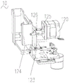
Referring to fig. 12 and 13, the blade-pushing wiping mechanism 10 includes a fixing base 11 and a wiping unit 12, the fixing base 11 is fixedly connected to the substrate 40, the wiping unit 12 is slidably connected to the fixing base 11, and the wiping unit 12 is provided with a wiping member 13 for wiping the blade 25 of the blade-pushing mechanism 20. The blade-pushing wiping mechanism 10 further includes a second driving member 14 (see fig. 14), the second driving member 14 is mounted on the fixed seat 11 and configured to drive the wiping unit 12 to reciprocate relative to the fixed seat 11 to wipe the blade 25 of the blade-pushing mechanism 20.
In the present embodiment, the wiping unit 12 drives the wiper 13 to reciprocate relative to the fixed seat 11 to wipe the blade 25 of the blade pushing mechanism 20, which is shorter than the prior art in which the blade is cleaned by ultrasonic waves.
Further, the wiping unit 12 is provided with a wiping position, the wiper 13 includes a wiping tape 131, a plurality of wiping portions 1311 are formed on the wiping tape 131, and the wiping tape 131 is movable relative to the wiping unit 12 so that the plurality of wiping portions 1311 are alternatively provided at the wiping position. Wherein the moving direction of the wiping belt 131 is perpendicular to the moving direction (second direction) of the wiping unit 12. That is, in the present embodiment, the blade pushing mechanism 20 is fixed relative to the substrate 40, the wiping unit 12 of the blade pushing and wiping mechanism 10 moves relative to the substrate 40 to drive the wiping portion 1311 to reciprocate in the second direction to wipe the blade 25, and the different wiping portions 1311 are used to wipe the blade 25 once, so as to avoid cross infection.
Further, the wiping part 1311 can carry a cleaning medium, the cleaning medium is injected onto the wiping part 1311, and the cleaning medium dissolves the liquid adhered to the push piece 25, so as to further improve the cleaning effect on the push piece 25 of the push piece mechanism 20, and compared with the prior art in which an ultrasonic cleaning mode is adopted, the use amount of the cleaning medium is small. Of course, in other embodiments, the cleaning medium may be directly injected onto the push-piece 25, the cleaning medium dissolves the liquid adhered to the push-piece 25, and the wiping portion 1311 only has a wiping effect.
With continued reference to FIG. 14, the push-piece wiping mechanism 10 also includes a priming member 110, the priming member 110 being configured to inject cleaning media onto the wiper 13 or the push-piece 25. Specifically, the liquid injection member 110 is disposed on the fixing base 11 or the wiping unit 12, and is a liquid injection pipe. When the cleaning medium needs to be sprayed to the wiping part 1311, the liquid injection pipe is communicated with an external pump body, the cleaning medium is pumped into the liquid injection pipe by the external pump body, and the cleaning medium is sprayed to the wiping part 1311 by the liquid injection pipe.
In one embodiment, the second direction is perpendicular to the third direction, i.e., the first direction is perpendicular to the length direction of the slide 200 and parallel to both the width direction of the slide 200 and the width direction of the push-piece 25, so that the push-piece wiping mechanism 10 can wipe the push-piece 25 in the width direction.
With reference to fig. 12, the blade-pushing wiping mechanism 10 further includes a third slide rail 15 and a third slider 16, one of the third slide rail 15 and the third slider 16 is disposed on the fixing base 11, the other one is disposed on the wiping unit 12, and the third slide rail 15 and the third slider 16 are slidably engaged to realize the sliding connection between the wiping unit 12 and the fixing base 11. The second driving member 14 includes a second driving motor 141, the blade-pushing wiping mechanism 10 further includes a first connecting rod 191 and a second connecting rod 192, one end of the first connecting rod 191 is fixedly connected with the driving shaft of the second driving member 14, the other end of the first connecting rod 191 is hinged with one end of the second connecting rod 192, and the other end of the second connecting rod 192 is hinged with the wiping unit 12. Thus, when the second driving member 14 is operated, the first connecting rod 191 is engaged with the second connecting rod 192, and the third sliding rail 15 is guided by the third sliding block 16 to cooperate with the wiping unit 12 to reciprocate in the second direction, so as to achieve the effect of wiping the pushing sheet 25.
The blade pushing and wiping mechanism 10 further includes a second sensing switch 17 and a second sensing blade 18, specifically, the second sensing blade 18 is disposed at the driving end of the second driving member 14 or on the first connecting rod 191, the second sensing switch 17 is disposed on the fixing base 11, and the second sensing switch 17 can sense the rotation angle of the second sensing blade 18, so as to control the rotation angle of the second driving motor 141, and control the number of times of the reciprocating motion of the wiping unit 12 in the second direction.
With continued reference to fig. 1, 12-13, and 15-16, in one embodiment, the wiper 13 further includes a cartridge 132, the wiping unit 12 is provided with a receiving cavity 122 therein, and the cartridge 132 is received in the receiving cavity 122. The tape cassette 132 is provided with a housing chamber, the wiper 13 further includes a first winding member 135 and a second winding member 136, at least a portion of the first winding member 135 and the second winding member 136 is provided with the housing chamber, one end of the wiping tape 131 is connected to the first winding member 135, the other end of the wiping tape 131 is connected to the second winding member 136, and the wiping tape 131 can move relative to the tape cassette 132 by means of the first winding member 135 and the second winding member 136.
The wiper 13 further includes a positioning block 133, the positioning block 133 is provided on the tape cassette 132, the tape cassette 132 is further provided with a first opening 1321 communicating with the housing chamber, and the wiping tape 131 passes through the first opening 1321 and abuts on the positioning block 133 when being wound around 135 from the first winding member on the second winding member 136.
When the push piece 25 of the push piece mechanism 20 needs to be cleaned, the push piece 25 is in contact with the wiping belt 131, and the wiping belt 131 is clamped and positioned between the positioning block 50 and the push piece 25 under the action force applied to the wiping belt 131 by the push piece 25, so that the friction force between the push piece 25 and the wiping belt 131 is increased, and the cleaning effect on the push piece 25 of the push piece mechanism 20 is improved under the condition that the friction force between the push piece 25 and the wiping belt 131 is increased.
Here, the wiping tape 131 passes through the first opening 1321 and abuts against the positioning block 133 when being wound around the second winding member 136 from the first winding member 135, and includes the following cases:
in one embodiment, the wiping strip 131 is wound from the first winding member 135 onto the second winding member 136, passes out of the receiving cavity through the first opening 1321 to abut against the positioning block 133, and re-passes into the receiving cavity from the first opening 1321. In another embodiment, the wiping band 131 is wound around the second winding member 136 from the first winding member 135, passes through the first opening 1321, out of the accommodating cavity to abut against the positioning block 133, and re-passes through the other opening into the accommodating cavity. In yet another embodiment, the wiping strip 131 is wound from the first winding member 135 onto the second winding member 136 through the other opening out of the receiving cavity to abut against the positioning block 133, and is re-inserted into the receiving cavity from the first opening 1321.
Here, the fact that the wiping tape 131 is wound around the second winding element 136 from the first winding element 135 and is passed out of the accommodation cavity through the first opening 1321 to abut against the positioning block 133 means that: the wiping belt 131 abuts against a portion of the positioning block 133 so that the wiping belt 131 is sandwiched and positioned between the positioning block 133 and the push piece 25 when the push piece 25 is cleaned.
In one embodiment, the tape cassette 132 has a hollow rectangular parallelepiped structure, that is, the cross-sectional shape of the tape cassette 132 is rectangular, the first winding member 135 and the second winding member 136 are both flat and disc-shaped, the axial directions of the first winding member 135 and the second winding member 136 are parallel to the thickness direction of the tape cassette 132, and the first winding member 135 and the second winding member 136 are arranged in the tape cassette 132 side by side.
Here, since the wiping tape 131 is wound around the outer peripheries of the first winding member 135 and the second winding member 136, the second direction is the thickness direction of the tape cassette 132 or the axial direction of the first winding member 135 and the second winding member 136 since the second direction is the width direction of the wiping tape 131.
Specifically, the tape cassette 132 includes a first half 1324 and a second half 1325 that are separately disposed, and the first half 1324 and the second half 1325 are spliced to form the tape cassette 132. So configured, assembly of the first winding member 135, the second winding member 136 and the wiping tape 131 is facilitated.
In an embodiment, all of the first winding element 135 and the second winding element 136 are disposed in the accommodating cavity, the first winding element 135 is provided with a first mounting hole, the second winding element 136 is provided with a second mounting hole, the tape cassette 132 is provided with a first through hole at a position corresponding to the first mounting hole, and a second through hole at a position corresponding to the second mounting hole. So set up, be convenient for outside actuating mechanism locate in the first mounting hole from first through-hole, locate in the second mounting hole from the second through-hole to the drive is wiped and is taken 131 and rotate for tape cartridge 132. It should be understood that, in other embodiments, portions of the first winding element 135 and the second winding element 136 may be disposed in the accommodating cavity, a remaining portion of the first winding element 135 extends out of the first through hole, and a remaining portion of the second winding element 136 extends out of the second through hole and is connected to an external driving mechanism, so as to drive the wiping tape 131 to rotate relative to the tape cassette 132.
Further, during the movement of the wiping tape 131 relative to the tape cassette 132, one of the first winding member 135 and the second winding member 136 for winding up the wiping tape 131 serves as a driving member, and the other serves as a driven member by the pulling action of the wiping tape 131.
Referring to fig. 17, the blade-pushing wiping mechanism 10 further includes a third driving member 120, the third driving member 120 includes a third driving motor 130 and a driven shaft 140, the third driving motor 130 has a driving shaft 150, the first winding member 135 is connected to the driving shaft 150, and the second winding member 136 is connected to the driven shaft 140. The third driving motor 130 drives the first winding member 135 to wind the wiping tape 131, and the second winding member 136 releases the wiping tape 131 by pulling the wiping tape 131, so that the plurality of wiping parts 1311 are alternatively disposed at the wiping position. It should be understood that in other embodiments, the second winding element 136 may be connected to the driving shaft 150, and the second winding element 136 may be connected to the driven shaft 140, which is not limited herein.
With continued reference to fig. 18 and 19, the wiping unit 12 includes a first connecting plate 123 and a second connecting plate 124, the first connecting plate 123 is slidably connected to the fixing base 11, the second connecting plate 124 is movably connected to the first connecting plate 123, the third driving member 120 is disposed on the first connecting plate 123, and the receiving cavity 122 is disposed on the second connecting plate 124. The second connecting plate 124 is switchable between a first position and a second position relative to the first connecting plate 123, in the first position, the third driving member 120 limits the tape cassette 132 to the second connecting plate 124 (see fig. 18), and in the second position, the third driving member 120 allows the tape cassette 132 to be separated from the second connecting plate 124 (see fig. 19).
In the first position, the third driving member 120 limits the separation of the tape cassette 132 from the second connecting plate 124, so as to ensure that the tape cassette 132 is firmly connected with the second connecting plate 124 in the normal working state; in the second position, the third drive member 120 allows the cartridge 132 to be separated from the second coupling plate 124, facilitating replacement of the cartridge 132.
When the second connecting plate 124 is at the first position, the driving shaft 150 passes through the first through hole and is disposed in the first mounting hole, and the driven shaft 140 passes through the second through hole and is disposed in the second mounting hole. In this embodiment, just as when the second connecting plate 124 is at the first position, the driving shaft 150 is inserted into the first mounting hole, and the driven shaft 140 is inserted into the second mounting hole, at this time, the driving shaft 150 and the driven shaft 140 separate the restraining belt box assembly from the second connecting plate 124; when the second connecting plate 124 is at the second position, the driving shaft 150 is separated from the first winding element 135, and the driven shaft 140 is separated from the second winding element 136, so that the third driving element 120 will not restrict the tape cartridge assembly from being separated from the second connecting plate 124.
With continued reference to fig. 15 and 16, in one embodiment, the wiper 13 further includes a resilient tab 137, the tab 137 is pressed against the follower to prevent the follower from rotating, which causes the wiper strip 131 to automatically release from the follower. Specifically, the tape cassette 132 is provided with a pressing port communicating with the accommodating chamber, and the pressing piece 137 is pressed and held on the driven member through the pressing port.
It should be understood that in other embodiments, the connection manner of the first winding member 135 and the second winding member 136 with the third driving member 120 is not limited thereto, and the first winding member 135 and the second winding member 136 may also be disposed to extend from the tape cassette 132 to connect with the third driving member 120.
With continued reference to fig. 18 and 19, the sliding plate 122 further includes a mounting piece 125 and a fitting piece 126, the mounting piece 125 is movably connected to one of the first connecting plate 123 and the second connecting plate 124, and the fitting piece 126 is connected to the other of the first connecting plate 123 and the second connecting plate 124. Wherein, fitting piece 126 and installation piece 125 swing joint can switch between third position and fourth position for installation piece 125 with regard to, and when the third position, fitting piece 126 and installation piece 125 cooperation are spacing second connecting plate 124 to the first position, and when the fourth position, fitting piece 126 and installation piece 125 cooperation are spacing second connecting plate 124 to the second position. With the above arrangement, it can be ensured that the second connecting plate 124 is stably located at the first position and the second position.
Specifically, one end of the mounting piece 125 is hinged to the second connecting plate 124, the other end of the mounting piece is provided with an L-shaped limiting groove 1251 (see fig. 20), the fitting piece 126 is a clamping column connected to the first connecting plate 123, the clamping column extends into the limiting groove 1251, and the clamping column can move in the limiting groove 1251. When the latch moves to the limit position (third position) of one end thereof in the limiting groove 1251, the latch limits the second connecting plate 124 to the first position, and when the latch moves to the limit position (fourth position) of the other end thereof in the limiting groove 1251, the latch limits the second connecting plate 124 to the second position.
In an embodiment, the first opening 1321 is opened at a right-angled vertex of the tape cassette 132, the positioning block 133 is disposed at the same right-angled vertex of the tape cassette 132, a right-angled portion 1331 (see fig. 21 and 22) is formed on the positioning block 133, and the wiping portion 1311 can be bent under the action of the push piece 25 and abut against the right-angled portion 1331, so as to position the wiping portion 1311 and the push piece 25, thereby facilitating the wiping of the push piece 25.
With continuing reference to fig. 13 and with further reference to fig. 23, in an embodiment, the positioning block 133 is pivotally connected to the tape cartridge 132, and the positioning block 133 can swing with respect to the tape cartridge 132. Specifically, the positioning block 133 is pivotally connected to the cartridge 132 by a first shaft, and a rotation axis of the positioning block 133 with respect to the cartridge 132 is parallel to rotation axes of the first winding member 135 and the second winding member 136. With reference to fig. 13, the wiper 13 further includes a limiting member (not shown) for limiting the swing position of the positioning block 133 relative to the tape cassette 132, the limiting member includes a first sub-limiting member 1381 and a second sub-limiting member 1382, and the first sub-limiting member 1381 and the second sub-limiting member 1382 are respectively disposed at two sides of the positioning block 133 in the swing direction of the positioning block 133 relative to the tape cassette 132. With this arrangement, when the push piece 25 applies a force to the wiping portion 1311, since the positioning block 133 can rotate relative to the tape cassette 132, the push piece 25 can push the wiping portion 1311 to abut against the right-angled portion 1331, positioning of the wiping portion 1311 can be facilitated, and the adaptability of the positioning block 133 can be improved.
The first sub-limiting member 1381 and/or the second sub-limiting member 1382 have elasticity. When the first sub-limiting member 1381 and/or the second sub-limiting member 1382 have elasticity, the positioning block 133 can be automatically reset under the elastic restoring force when the pushing piece 25 releases the positioning block 133.
The first sub-limiting member 1381 has elasticity, and specifically, the first sub-limiting member 1381 is a torsion spring, the torsion spring includes a second body and a first end and a second end respectively connected to the second body, and the second body is connected to the tape cassette 132. More specifically, the second body is sleeved on a second shaft protruding from the tape cassette 132, and has a first end abutting against the tape cassette 132 and a second end abutting against the positioning block 133. Thus, when the pushing piece 25 applies an acting force to the wiping tape 131, the positioning block 133 swings relative to the tape cartridge 132 under the driving of the wiping tape 131, and the positioning block 133 causes the torsion spring to elastically deform, so that the position of the positioning block 133 relative to the tape cartridge 132 is finely adjusted, the pushing piece 25 abuts against the wiping portion 1311 and the right-angled portion 1331, the wiping portion 1311 is conveniently positioned, and the self-adaptability of the positioning block 133 is improved.
The second sub-limiting member 1382 is a protrusion protruding from the tape cassette 132 to cooperate with the first sub-limiting member 1381 to limit the position of the positioning block 133 relative to the tape cassette 132. Specifically, the second sub-limiting member 1382 is disposed on the second half-shell 16 in a protruding manner.
With reference to fig. 22, in an embodiment, the positioning block 133 is provided with an elastic element 134, and the elastic element 134 is used for abutting against the wiping strip 131. Further, the elastic member 134 has a first abutting plane 1341 and a second abutting plane 1342 located on both sides of the right-angled portion 1331, and the wiping tape 131 abuts both the first abutting plane 1341 and the second abutting plane 1342. With such an arrangement, when the push plate 200 needs to be cleaned, the elastic element 134 is elastically deformed to apply an elastic restoring force to the push plate 25, so that the wiping belt 131 is more tightly clamped between the positioning block 133 and the push plate 25, thereby increasing the friction force between the push plate 25 and the wiping portion 1311 and improving the wiping effect.
Specifically, the elastic member 134 is made of a rubber material, and the elastic member 134 is integrally molded with the positioning block 133. It should be understood that in other embodiments, the elastic element 134 is not limited to be made of rubber, and the elastic element 134 may be provided separately from the positioning block 133.
Referring to fig. 13, 16 and 23, in an embodiment, the wiper 13 further includes a first belt guiding member 1391 and a second belt guiding member 1392, and the first belt guiding member 1391 and the second belt guiding member 1392 are respectively located upstream and downstream of the positioning block 133 in the moving direction of the wiper 131 relative to the tape cassette 132. So configured, the first and second belt guides 1391 and 1392 can limit the angle of the wiping belt 131 and facilitate tensioning of the wiping belt 131 when the wiping belt 131 enters and exits the first opening 1321. Specifically, the first and second belt guides 1391, 1392 are each disposed adjacent to the first opening 1321.
In one embodiment, the tape cassette 132 further has a second opening 1322 communicating with the receiving cavity, and the wiper 13 further includes a third tape guide 1393, the third tape guide 1393 is disposed on the tape cassette 132, and the wiper 131 passes through the second opening 1322 from the first winding member 135 to abut against the third tape guide 1393 when the wiper 131 is wound on the second winding member 136. In this way, the third belt guide 1393 can function to support the wiping belt 131 in cooperation with the first and second belt guides 1391 and 1392. The blade wiping mechanism 10 further includes a counter wheel 1120 (see fig. 14) provided on the first connecting plate 123, and the wiping belt 131 is held between the third belt guiding member 1393 and the counter wheel 1120. When the wiping tape 131 rotates with respect to the tape cassette 132, the counting wheel 1120 rotates by a frictional force applied thereto by the wiping tape 131, depending on the number of rotations thereof or the length of movement of the wiping tape 131.
With reference to fig. 14, the blade-pushing wiping mechanism 10 further includes a counting plate 1130 and a third sensing switch 1140, the third sensing switch 1140 is disposed on the first connecting plate 123, the counting plate 1130 is in transmission connection with the counting wheel 1120, the third sensing switch 1140 can sense the number of turns of the counting plate 1130 to transmit a signal to the controller, and the controller controls the rotation angle of the third driving member 120 to control the moving length of the wiping belt 131.
With continued reference to fig. 13, in one embodiment, the third belt guiding element 1393 and the positioning block 133 are disposed at two right-angled vertices of the tape cartridge 132, respectively, along the length of the tape cartridge 132. Of course, in other embodiments, the arrangement positions of the counting tape guide 80 and the positioning block 133 are not limited.
Specifically, the tape cassette 132 is provided with an observation window 1323, and the amount of the wiping tape 131 wound around the first winding member 135 and the second winding member 136 can be observed through the observation window 1323. It should be appreciated that in other embodiments, the entire tape cassette 132 may be made of a transparent material to facilitate viewing the amount of the wiping tape 131 wound around the first winding member 135 and the second winding member 136.
The working principle of the blade pushing device 100 provided by the embodiment of the invention is as follows:
when it is desired to flatten the blood on the slide 200:
the push piece 25 of the push piece mechanism 20 rotates to a push piece position relative to the mounting seat 21, and the inclination angle between the push piece 25 and the slide glass 200 is in the range of 0-90 degrees. When the push piece 25 contacts with the slide glass 200, an interaction force is generated between the slide glass 200 and the push piece 25, the push piece 25 transmits the interaction force to the mounting block 24, the mounting block 24 compresses the first elastic member 26, the second mounting plate 212 transmits the interaction force to the second elastic member 29, the second mounting plate 212 slides relative to the first mounting plate 211, and the first elastic member 26 and the second elastic member 29 elastically deform to ensure that the push piece 25 is tightly attached to the slide glass 200.
When the fourth driving motor 321 of the slide mechanism 30 rotates forward, the driving wheel 322 is driven to rotate, the belt 323 drives the driven wheel 324 to rotate, the screw rod 325 rotates forward, the slide holder 33 drives the slide 200 to move forward in the third direction, and the push piece 25 of the push piece mechanism 20 pushes the blood on the slide 200 flat. The slide mechanism 30 then returns to the origin.
When the push piece 25 needs to be wiped:
the injection member 110 injects the cleaning medium onto the wiping part 1311, and the third driving motor 130 rotates to bring the wet wiping part 1311 to the wiping position. The pushing piece 25 of the pushing piece mechanism 20 rotates to the cleaning position relative to the mounting seat 21, the second driving element 14 drives the wiping unit 12 to reciprocate in the second direction, and the positioning block 133 presses the wiping part 1311 against the pushing piece 25, so as to wipe the pushing piece 25.
Another embodiment of the present invention further provides a blade wiping mechanism 10 included in the blade pushing device 100.
The technical features of the embodiments described above may be arbitrarily combined, and for the sake of brevity, all possible combinations of the technical features in the embodiments described above are not described, but should be considered as being within the scope of the present specification as long as there is no contradiction between the combinations of the technical features.
The above-mentioned embodiments only express several embodiments of the present invention, and the description thereof is specific and detailed, but not to be understood as limiting the scope of the invention. It should be noted that, for a person skilled in the art, several variations and modifications can be made without departing from the inventive concept, which falls within the scope of the present invention. Therefore, the protection scope of the present patent shall be subject to the appended claims.
Claims (10)
1. A push-piece wiping mechanism, characterized in that it comprises:
a fixed seat;
the wiping unit is slidably arranged on the fixed seat, and a wiping piece for wiping a push sheet of the push sheet mechanism is arranged on the wiping unit;
the second driving part is installed on the fixed seat and is configured to drive the wiping unit to reciprocate relative to the fixed seat so that the wiping part wipes the push sheet of the push sheet mechanism.
2. The pusher wiping mechanism according to claim 1, wherein a wiping position is provided on the wiping unit, and the wiper member includes a wiping belt on which a plurality of wiping portions are formed, the wiping belt being movable relative to the wiping unit to alternatively place the plurality of wiping portions in the wiping position;
wherein a moving direction of the wiping belt is perpendicular to a moving direction of the wiping unit.
3. The blade pushing and wiping mechanism according to claim 2, wherein said wiping member further comprises a tape cassette provided on said wiping unit, said wiping tape being provided in said tape cassette, a first winding member and a second winding member being provided in said tape cassette, one end of said wiping tape being connected to said first winding member, the other end of said wiping tape being connected to said second winding member, said wiping tape being moved relative to said tape cassette by means of said first winding member and said second winding member.
4. The blade wiping mechanism of claim 3 further comprising a third drive member including a drive shaft and a driven shaft, one of the first and second winders being connected to the drive shaft and the other of the first and second winders being connected to the driven shaft.
5. The mechanism of claim 4, wherein the wiper unit includes a first link plate slidably connected to the holder and a second link plate movably connected to the first link plate, the cartridge being mounted on the second link plate;
the second connecting plate can be switched between a first position and a second position relative to the first connecting plate, the third driving piece limits the tape cassette to the second connecting plate in the first position, and the third driving piece allows the tape cassette to be separated from the second connecting plate in the second position.
6. The blade wiping mechanism according to claim 5, wherein the wiping unit further comprises a mounting blade movably connected to one of the first connecting plate and the second connecting plate, and a fitting member connected to the other of the first connecting plate and the second connecting plate;
the fitting piece is movably connected with the mounting piece so as to be capable of being switched between a third position and a fourth position relative to the mounting piece, when the third position is reached, the fitting piece is matched with the mounting piece to limit the second connecting plate to the first position, and when the fourth position is reached, the fitting piece is matched with the mounting piece to limit the second connecting plate to the second position.
7. The mechanism of claim 2, further comprising a third sensor switch, a counting plate and a counting wheel, wherein the counting wheel abuts against the wiping belt and rotates under the friction force of the wiping belt, the counting plate is in transmission connection with the counting wheel, and the third sensor switch is configured to sense the rotation angle of the counting plate.
8. The blade pushing and wiping mechanism of claim 1 further comprising a first link and a second link, wherein one end of the first link is fixedly connected to the second driving member, the other end of the first link is hinged to one end of the second link, and the other end of the second link is hinged to the wiping unit.
9. The push-piece wiping mechanism according to claim 1, further comprising a liquid injection member configured to be able to inject a cleaning medium onto the wiper member or the push-piece.
10. A blade pushing device comprising a blade pushing mechanism and a blade pushing and wiping mechanism as claimed in any one of claims 1 to 9, wherein the blade pushing mechanism comprises a blade which can be switched between a blade pushing position and a cleaning position.
Priority Applications (1)
| Application Number | Priority Date | Filing Date | Title |
|---|---|---|---|
| CN202110162450.0A CN114850083B (en) | 2021-02-05 | 2021-02-05 | Push-piece wiping mechanism and push-piece device |
Applications Claiming Priority (1)
| Application Number | Priority Date | Filing Date | Title |
|---|---|---|---|
| CN202110162450.0A CN114850083B (en) | 2021-02-05 | 2021-02-05 | Push-piece wiping mechanism and push-piece device |
Publications (2)
| Publication Number | Publication Date |
|---|---|
| CN114850083A true CN114850083A (en) | 2022-08-05 |
| CN114850083B CN114850083B (en) | 2024-03-12 |
Family
ID=82628373
Family Applications (1)
| Application Number | Title | Priority Date | Filing Date |
|---|---|---|---|
| CN202110162450.0A Active CN114850083B (en) | 2021-02-05 | 2021-02-05 | Push-piece wiping mechanism and push-piece device |
Country Status (1)
| Country | Link |
|---|---|
| CN (1) | CN114850083B (en) |
Citations (5)
| Publication number | Priority date | Publication date | Assignee | Title |
|---|---|---|---|---|
| CN202845356U (en) * | 2012-10-26 | 2013-04-03 | 世成电子(深圳)有限公司 | Clean machine |
| WO2013152697A1 (en) * | 2012-04-10 | 2013-10-17 | 深圳迈瑞生物医疗电子股份有限公司 | Method and device for cleaning applicator paddle of paddle dyeing machine |
| CN105598047A (en) * | 2015-12-20 | 2016-05-25 | 重庆路格科技有限公司 | Cleaning device for navigator |
| CN110369349A (en) * | 2019-07-25 | 2019-10-25 | 苏州凌云视界智能设备有限责任公司 | Liquid crystal display wiping arrangement |
| CN110508584A (en) * | 2019-08-16 | 2019-11-29 | 昆山维信诺科技有限公司 | A kind of cleaning device |
-
2021
- 2021-02-05 CN CN202110162450.0A patent/CN114850083B/en active Active
Patent Citations (6)
| Publication number | Priority date | Publication date | Assignee | Title |
|---|---|---|---|---|
| WO2013152697A1 (en) * | 2012-04-10 | 2013-10-17 | 深圳迈瑞生物医疗电子股份有限公司 | Method and device for cleaning applicator paddle of paddle dyeing machine |
| CN103364252A (en) * | 2012-04-10 | 2013-10-23 | 深圳迈瑞生物医疗电子股份有限公司 | Smear cleaning method and device of smear dyeing machine |
| CN202845356U (en) * | 2012-10-26 | 2013-04-03 | 世成电子(深圳)有限公司 | Clean machine |
| CN105598047A (en) * | 2015-12-20 | 2016-05-25 | 重庆路格科技有限公司 | Cleaning device for navigator |
| CN110369349A (en) * | 2019-07-25 | 2019-10-25 | 苏州凌云视界智能设备有限责任公司 | Liquid crystal display wiping arrangement |
| CN110508584A (en) * | 2019-08-16 | 2019-11-29 | 昆山维信诺科技有限公司 | A kind of cleaning device |
Also Published As
| Publication number | Publication date |
|---|---|
| CN114850083B (en) | 2024-03-12 |
Similar Documents
| Publication | Publication Date | Title |
|---|---|---|
| CA2524812C (en) | Analysis system for analysis of a liquid sample on an analytical test element | |
| US6827899B2 (en) | Test device | |
| JP5579968B2 (en) | Specimen dispenser | |
| US7758808B2 (en) | Manual device for examining a body fluid | |
| US9671387B2 (en) | Test system | |
| KR20130095781A (en) | Test element ejection mechanism for a meter | |
| WO2003042691A1 (en) | Sensor dispensing device | |
| JP2009042227A (en) | Forwarding device of testing element | |
| AU2005215484A1 (en) | Strip ejection system | |
| TW201337264A (en) | Hand-held test meter with analytical test strip ejection mechanism | |
| CN214638402U (en) | Tape box | |
| CN114850083A (en) | Pushing piece wiping mechanism and pushing piece device | |
| CN114878262A (en) | Blade pushing mechanism and blade pushing device | |
| JP3977439B2 (en) | Device for enclosing histological and biological samples | |
| CN114871160A (en) | Tape box | |
| US9289170B2 (en) | Apparatus for eliciting a blood sample | |
| CN111521837B (en) | Detection device | |
| CN219397569U (en) | Limiting structure for needle insertion of puncture needle and puncture needle clamping device | |
| CN106885718B (en) | Disposable doctor blade system and automatic blood smear making instrument | |
| CN220552811U (en) | Sample analysis device and blood gas analysis device | |
| CN216160291U (en) | Compact indentation appearance | |
| WO2022011848A1 (en) | Optical fiber cleaving device | |
| CN215115172U (en) | Regulator testing device | |
| CN212658855U (en) | Optical fiber cutting device | |
| CN112254825A (en) | Box type infrared temperature measuring device |
Legal Events
| Date | Code | Title | Description |
|---|---|---|---|
| PB01 | Publication | ||
| PB01 | Publication | ||
| SE01 | Entry into force of request for substantive examination | ||
| SE01 | Entry into force of request for substantive examination | ||
| GR01 | Patent grant | ||
| GR01 | Patent grant |