CN114837482A - In-situ precipitation slag pit and installation method thereof - Google Patents
In-situ precipitation slag pit and installation method thereof Download PDFInfo
- Publication number
- CN114837482A CN114837482A CN202210638157.1A CN202210638157A CN114837482A CN 114837482 A CN114837482 A CN 114837482A CN 202210638157 A CN202210638157 A CN 202210638157A CN 114837482 A CN114837482 A CN 114837482A
- Authority
- CN
- China
- Prior art keywords
- base
- situ precipitation
- slag pit
- filter wall
- precipitation slag
- Prior art date
- Legal status (The legal status is an assumption and is not a legal conclusion. Google has not performed a legal analysis and makes no representation as to the accuracy of the status listed.)
- Pending
Links
- 238000000034 method Methods 0.000 title claims abstract description 27
- 238000011065 in-situ storage Methods 0.000 title claims abstract description 26
- 239000002893 slag Substances 0.000 title claims abstract description 25
- 238000001556 precipitation Methods 0.000 title claims abstract description 24
- 238000009434 installation Methods 0.000 title abstract description 19
- XLYOFNOQVPJJNP-UHFFFAOYSA-N water Substances O XLYOFNOQVPJJNP-UHFFFAOYSA-N 0.000 claims abstract description 60
- 238000001914 filtration Methods 0.000 claims abstract description 46
- 239000004575 stone Substances 0.000 claims abstract description 42
- 229910000831 Steel Inorganic materials 0.000 claims abstract description 40
- 239000010959 steel Substances 0.000 claims abstract description 40
- 230000003014 reinforcing effect Effects 0.000 claims abstract description 12
- 239000000463 material Substances 0.000 claims description 9
- 230000002787 reinforcement Effects 0.000 claims description 9
- 238000004064 recycling Methods 0.000 claims 1
- 238000010276 construction Methods 0.000 abstract description 12
- 230000008569 process Effects 0.000 abstract description 8
- 239000002245 particle Substances 0.000 description 30
- 239000002689 soil Substances 0.000 description 17
- 208000005156 Dehydration Diseases 0.000 description 7
- 230000018044 dehydration Effects 0.000 description 7
- 238000006297 dehydration reaction Methods 0.000 description 7
- 239000007788 liquid Substances 0.000 description 7
- 238000007599 discharging Methods 0.000 description 4
- 230000000694 effects Effects 0.000 description 4
- 238000005406 washing Methods 0.000 description 4
- 238000013461 design Methods 0.000 description 3
- 239000002002 slurry Substances 0.000 description 3
- 230000009286 beneficial effect Effects 0.000 description 2
- 230000007613 environmental effect Effects 0.000 description 2
- 230000008595 infiltration Effects 0.000 description 2
- 238000001764 infiltration Methods 0.000 description 2
- 230000004048 modification Effects 0.000 description 2
- 238000012986 modification Methods 0.000 description 2
- 238000005086 pumping Methods 0.000 description 2
- 230000005641 tunneling Effects 0.000 description 2
- 230000009471 action Effects 0.000 description 1
- 238000011161 development Methods 0.000 description 1
- 238000003912 environmental pollution Methods 0.000 description 1
- 238000011010 flushing procedure Methods 0.000 description 1
- 230000006872 improvement Effects 0.000 description 1
- 239000002184 metal Substances 0.000 description 1
- 230000000149 penetrating effect Effects 0.000 description 1
- 238000012545 processing Methods 0.000 description 1
- 238000003466 welding Methods 0.000 description 1
Images


Classifications
-
- E—FIXED CONSTRUCTIONS
- E04—BUILDING
- E04H—BUILDINGS OR LIKE STRUCTURES FOR PARTICULAR PURPOSES; SWIMMING OR SPLASH BATHS OR POOLS; MASTS; FENCING; TENTS OR CANOPIES, IN GENERAL
- E04H7/00—Construction or assembling of bulk storage containers employing civil engineering techniques in situ or off the site
- E04H7/02—Containers for fluids or gases; Supports therefor
-
- B—PERFORMING OPERATIONS; TRANSPORTING
- B01—PHYSICAL OR CHEMICAL PROCESSES OR APPARATUS IN GENERAL
- B01D—SEPARATION
- B01D29/00—Filters with filtering elements stationary during filtration, e.g. pressure or suction filters, not covered by groups B01D24/00 - B01D27/00; Filtering elements therefor
- B01D29/01—Filters with filtering elements stationary during filtration, e.g. pressure or suction filters, not covered by groups B01D24/00 - B01D27/00; Filtering elements therefor with flat filtering elements
- B01D29/03—Filters with filtering elements stationary during filtration, e.g. pressure or suction filters, not covered by groups B01D24/00 - B01D27/00; Filtering elements therefor with flat filtering elements self-supporting
-
- B—PERFORMING OPERATIONS; TRANSPORTING
- B01—PHYSICAL OR CHEMICAL PROCESSES OR APPARATUS IN GENERAL
- B01D—SEPARATION
- B01D29/00—Filters with filtering elements stationary during filtration, e.g. pressure or suction filters, not covered by groups B01D24/00 - B01D27/00; Filtering elements therefor
- B01D29/11—Filters with filtering elements stationary during filtration, e.g. pressure or suction filters, not covered by groups B01D24/00 - B01D27/00; Filtering elements therefor with bag, cage, hose, tube, sleeve or like filtering elements
- B01D29/13—Supported filter elements
- B01D29/23—Supported filter elements arranged for outward flow filtration
- B01D29/27—Filter bags
-
- B—PERFORMING OPERATIONS; TRANSPORTING
- B01—PHYSICAL OR CHEMICAL PROCESSES OR APPARATUS IN GENERAL
- B01D—SEPARATION
- B01D29/00—Filters with filtering elements stationary during filtration, e.g. pressure or suction filters, not covered by groups B01D24/00 - B01D27/00; Filtering elements therefor
- B01D29/50—Filters with filtering elements stationary during filtration, e.g. pressure or suction filters, not covered by groups B01D24/00 - B01D27/00; Filtering elements therefor with multiple filtering elements, characterised by their mutual disposition
-
- Y—GENERAL TAGGING OF NEW TECHNOLOGICAL DEVELOPMENTS; GENERAL TAGGING OF CROSS-SECTIONAL TECHNOLOGIES SPANNING OVER SEVERAL SECTIONS OF THE IPC; TECHNICAL SUBJECTS COVERED BY FORMER USPC CROSS-REFERENCE ART COLLECTIONS [XRACs] AND DIGESTS
- Y02—TECHNOLOGIES OR APPLICATIONS FOR MITIGATION OR ADAPTATION AGAINST CLIMATE CHANGE
- Y02W—CLIMATE CHANGE MITIGATION TECHNOLOGIES RELATED TO WASTEWATER TREATMENT OR WASTE MANAGEMENT
- Y02W30/00—Technologies for solid waste management
- Y02W30/50—Reuse, recycling or recovery technologies
Abstract
The invention relates to the technical field of mud dewatering, in particular to an in-situ dewatering slag pit and an installation method thereof. The in-situ precipitation slag pit comprises a base and a filter wall; the filter wall is arranged at the edge of the upper side of the base in a surrounding manner, and the filter wall and the base form a muck stacking space together; the base is provided with a first filtering device, the base is provided with a water collecting tank, and water obtained after the dregs in the dregs stacking space are filtered by the first filtering device is discharged out of the base through the water collecting tank. The installation method of the in-situ precipitation slag pit comprises the following steps: s1: pouring a bearing base; s2: pouring the upright columns and the corner columns on the base; s3: mounting the prefabricated reinforcing mesh on a base, and paving graded broken stones; s4: hoisting the prefabricated steel cage; s5: installing a feeding plate; s6: and putting graded broken stones into the prefabricated steel cage. The whole process of the invention is simple, does not need devices such as a centrifugal pump, a vacuum pump, a pressure pump and the like, has low cost and quick installation, and is convenient to construct and use in a shield construction site.
Description
Technical Field
The invention relates to the technical field of mud dewatering, in particular to an in-situ dewatering slag pit and an installation method thereof.
Background
In recent years, along with the development of underground space resources, many cities in China have developed a large amount of subway construction, and during urban subway tunnel construction, a shield method is high in mechanization degree and construction efficiency, and can reduce the influence on surrounding constructions, so that the method is widely applied. However, in the tunneling process of the shield tunneling machine, the generated shield muck particles are fine and have the characteristics of high water content, mud content and the like, mud leakage cannot be avoided in the outward transportation process, urban road pollution is caused, city appearance and city appearance are influenced, and when the water content of the muck is too high, the muck cannot be timely transported outward and even construction progress can be influenced. At present, the requirement on environmental protection in urban construction is higher and higher, and the problem that the shield muck is thrown and leaked when being transported outside to cause environmental pollution needs to be solved urgently.
In the prior art, to solve the problem, some methods perform slurry dehydration by a centrifugal method, some methods perform slurry dehydration by a vacuum pumping method, and some methods perform slurry dehydration by a pressurizing method. When the methods are used, the cost is high, the structure is complex, the space of a shield construction site is limited, the site construction is difficult, and the use is inconvenient.
Disclosure of Invention
The invention aims to provide an in-situ precipitation slag pit which is low in cost and convenient to build and use.
The embodiment of the invention is realized by the following steps:
in a first aspect, the invention provides an in-situ precipitation slag pit, which comprises a base and a filter wall;
the filter wall is arranged at the edge of the upper side of the base in a surrounding manner, and the filter wall and the base form a muck stacking space together;
the base is provided with a first filtering device, the base is provided with a water collecting tank, and water filtered by the first filtering device and discharged from the water collecting tank in the muck stacking space passes through the water collecting tank.
In an alternative embodiment, the first filter device comprises a mesh reinforcement, and graded crushed stone is laid on the upper surface of the mesh reinforcement.
In an alternative embodiment, the filter wall comprises a column, a corner post and a second filter device;
the upright posts and the corner posts are arranged on the base, and the second filtering devices are arranged between the adjacent upright posts or between the adjacent upright posts and the adjacent corner posts.
In an alternative embodiment, the upright and corner posts are cast on the base.
In an optional embodiment, the upright is H-shaped steel, and the corner post is angle steel.
In an alternative embodiment, the second filter device comprises a prefabricated steel cage filled with graded crushed stone.
In an alternative embodiment, the upper end of the prefabricated steel cage is provided with a feeding port.
In an alternative embodiment, two opposite sides of the feeding port are provided with feeding plates, and the feeding plates on the two opposite sides form a V shape.
In a second aspect, the present invention provides a method for installing an in-situ precipitation slag pit according to any one of the preceding embodiments, comprising the following steps:
s1: pouring a bearing base;
s2: pouring upright columns and corner columns on the base;
s3: mounting a prefabricated reinforcing mesh on the base, and paving graded broken stones;
s4: hoisting the prefabricated steel cage;
s5: installing a feeding plate;
s6: and throwing graded broken stones into the prefabricated steel cage.
In an alternative embodiment, the graded crushed stone is repeatedly used by flushing with high pressure water.
The embodiment of the invention has the beneficial effects that:
carry out the dead weight infiltration through filter wall and first filter equipment to the dregs bag in the dregs stacking space, the water in the dregs bag oozes from the dregs bag under the effect of dead weight and filters through first filter equipment or filter wall again after, collects the filtration liquid through the water catch bowl and discharges after can realizing the dehydration to the dregs.
The whole process of the invention is simple, does not need devices such as a centrifugal pump, a vacuum pump, a pressure pump and the like, has low cost and quick installation, and is convenient to construct and use in a shield construction site.
Drawings
In order to more clearly illustrate the technical solutions of the embodiments of the present invention, the drawings needed to be used in the embodiments will be briefly described below, it should be understood that the following drawings only illustrate some embodiments of the present invention and therefore should not be considered as limiting the scope, and for those skilled in the art, other related drawings can be obtained according to the drawings without inventive efforts.
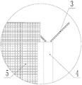
FIG. 1 is a front view of an in-situ precipitation slag pit provided by an embodiment of the invention;
FIG. 2 is an enlarged view of a portion of FIG. 1 at A;
FIG. 3 is a top view of an in-situ precipitation slag pit provided by embodiments of the present invention;
FIG. 4 is a partial enlarged view of FIG. 3 at B;
FIG. 5 is a schematic perspective view of an in-situ precipitation slag pit according to an embodiment of the present invention;
FIG. 6 is an exploded view of a portion of the three-dimensional structure of an in-situ precipitation pit according to an embodiment of the present invention;
fig. 7 is a perspective view of a base of an in-situ precipitation slag pit according to an embodiment of the invention.
Icon:
1: a base; 2: filtering walls; 3: feeding plates; 4: corner posts; 5: a second filtering device; 6: a first filtering device; 7: filling the space; 8: a column; 9: a base; 10: a first mounting groove; 11: a second mounting groove; 12: an internal sump; 13: a vertical water collecting hole; 14: a horizontal water collection hole; 15: an external sump; 16: and (4) draining the water.
Detailed Description
In order to make the objects, technical solutions and advantages of the embodiments of the present invention clearer, the technical solutions in the embodiments of the present invention will be clearly and completely described below with reference to the drawings in the embodiments of the present invention, and it is obvious that the described embodiments are some, but not all, embodiments of the present invention. The components of embodiments of the present invention generally described and illustrated in the figures herein may be arranged and designed in a wide variety of different configurations.
Thus, the following detailed description of the embodiments of the present invention, presented in the figures, is not intended to limit the scope of the invention, as claimed, but is merely representative of selected embodiments of the invention. All other embodiments, which can be derived by a person skilled in the art from the embodiments given herein without making any creative effort, shall fall within the protection scope of the present invention.
It should be noted that: like reference numbers and letters refer to like items in the following figures, and thus, once an item is defined in one figure, it need not be further defined and explained in subsequent figures.
In the description of the present invention, it should be noted that the terms "center", "upper", "lower", "left", "right", "vertical", "horizontal", "inner", "outer", etc. indicate orientations or positional relationships based on the orientations or positional relationships shown in the drawings or the orientations or positional relationships that the products of the present invention are conventionally placed in use, and are only used for convenience in describing the present invention and simplifying the description, but do not indicate or imply that the devices or elements referred to must have a specific orientation, be constructed and operated in a specific orientation, and thus, should not be construed as limiting the present invention. Furthermore, the terms "first," "second," "third," and the like are used solely to distinguish one from another and are not to be construed as indicating or implying relative importance.
Furthermore, the terms "horizontal", "vertical", "overhang" and the like do not imply that the components are required to be absolutely horizontal or overhang, but may be slightly inclined. For example, "horizontal" merely means that the orientation is more horizontal than "vertical" and does not mean that the pit must be perfectly horizontal, but may be slightly inclined.
In the description of the present invention, it should also be noted that, unless otherwise explicitly specified or limited, the terms "disposed," "mounted," "connected," and "connected" are to be construed broadly and may, for example, be fixedly connected, detachably connected, or integrally connected; can be mechanically or electrically connected; they may be connected directly or indirectly through intervening media, or they may be interconnected between two elements. The specific meanings of the above terms in the present invention can be understood in specific cases to those skilled in the art.
Some embodiments of the invention are described in detail below with reference to the accompanying drawings. The embodiments described below and the features of the embodiments can be combined with each other without conflict.
In a first aspect, the invention provides an in-situ precipitation slag pit, which comprises a base 1 and a filter wall 2; the filter wall 2 is arranged at the edge of the upper side of the base 1 in a surrounding manner, and the filter wall 2 and the base 1 jointly form a muck stacking space; the base 1 is provided with a first filtering device 6, the base 1 is provided with a water collecting tank, and water filtered by the first filtering device 6 in the residue soil stacking space is discharged out of the base 1 through the water collecting tank.
In this embodiment, base 1 sets up in the below, and filter wall 2 sets up immediately in base 1's top, and encloses and establish into a dregs stacking space, can be with piling up in dregs stacking space in unison through dregs, make dregs can utilize the dead weight to dewater, after the dregs dehydration, filtration liquid enters into the water catch bowl on base 1 through first filter equipment 6 or filter wall 2, and the water catch bowl assembles the back with filtration liquid after will filtering, outwards discharges again, carries out unified processing.
Specifically, in this embodiment, the base 1 includes a base 9 and an installation step, the installation step is used for installing the upright post 8, the corner post 4 and the filter wall 2, a first installation groove 10 and a second installation groove 11 are arranged on the installation step, the first installation groove 10 is used for installing the first filter device 6, and the second installation groove 11 is used for installing the filter wall 2.
More specifically, in the present embodiment, the water collecting tank includes an inner water collecting tank 12 and an outer water collecting tank 15, wherein the inner water collecting tank 12 is vertically and horizontally disposed at the bottom of the first mounting groove 10, and a part of the water collecting tank is communicated with a horizontal water collecting hole 14 penetrating the mounting step, the other end of the horizontal water collecting hole 14 is communicated with the outer water collecting tank 15 outside the mounting stand, the outer water collecting tank 15 is annularly disposed around the edge of the upper surface of the base 9, and a drain hole 16 is disposed at the corner for discharging water in the outer water collecting tank 15.
After the dregs are dehydrated by self weight, the percolate is discharged in two paths, the first path of percolate enters the inner water collecting tank 12 through the first filtering device 6, enters the outer water collecting tank 15 through the horizontal water collecting hole 14 and then is discharged out of the base 1 through the water discharging hole 16; the second path of percolate enters the second mounting groove 11 through the filter wall 2, the second mounting groove 11 is communicated with the vertical water collecting hole 13, enters the external water collecting tank 15 through the vertical water collecting hole 13 and then is discharged out of the base 1 through the water discharging hole 16.
In an alternative embodiment, the first filtering means 6 comprises a mesh reinforcement, the upper surface of which is laid graded crushed stone.
In this embodiment, the first filtering device 6 is a mesh of reinforcing bars, that is, the reinforcing bars arranged vertically and horizontally are fixedly connected to form a net structure for supporting the graded broken stones, so as to achieve the filtering effect under the action of the graded broken stones.
It should be noted that, in the present embodiment, the first filtering device 6 is a combination of a mesh reinforcement and graded crushed stones, but it is not limited to such a structure, and it may also be other structures, such as a mesh reinforcement arranged in multiple layers, that is, it only needs to support the muck bag and can achieve the effect of filtering the percolate.
In an alternative embodiment, the filtering wall 2 comprises uprights 8, corner posts 4 and second filtering means 5; the upright columns 8 and the corner columns 4 are both arranged on the base 1, and second filtering devices 5 are arranged between the adjacent upright columns 8 or between the upright columns 8 and the adjacent corner columns 4.
In this embodiment, the two sides of the upright post 8 are both provided with connecting grooves for connecting with the second filtering device 5, and the second filtering device 5 is inserted into the connecting grooves for fixing to form a whole.
Specifically, in the present embodiment, the pillar 8 is configured as an H-shaped steel, and the corner post 4 is configured as an angle steel.
Such setting can enough guarantee the intensity of stand 8 and corner post 4, can be convenient for again stand 8, corner post 4 and second filter equipment 5 be connected.
In this embodiment, the base 1 is rectangular or square in plan view, the corner posts 4 are disposed at four corners of the base 1, at least one upright post 8 is disposed between two adjacent corner posts 4, and the two adjacent upright posts 8 and the corner posts 4 and the adjacent upright posts 8 are connected by the second filtering device 5, so as to form an integral wall structure with filtering function.
In an alternative embodiment, the uprights 8 and corner posts 4 are cast on the foundation 1.
In this embodiment, base 1 forms for concrete placement, and in order to make things convenient for the installation of stand 8 and corner post 4, at the in-process of pouring base 1, can pour stand 8 and corner post 4 simultaneously on base 1 for stand 8 and corner post 4 are direct integrative with base 1 shape, have both guaranteed joint strength and the connection stability of corner post 4, stand 8 on base 1, make the installation become comparatively simple and convenient again.
It should be noted that, in this embodiment, the arrangement mode of the upright column 8 and the corner post 4 on the base 1 may be the arrangement mode by pouring, or may be other arrangement modes, for example, when the base 1 is made of metal, the upright column 8 and the base 1 may be connected by welding, riveting, or the like, or when the base 1 is made of concrete, the upright column 8 and the corner post 4 may be fixedly connected by embedded bolts, that is, as long as the upright column 8 and the corner post 4 can be fixedly arranged on the base 1.
In an alternative embodiment, the second filtering means 5 comprise a prefabricated steel cage filled with graded crushed stones.
Specifically, in this embodiment, second filter equipment 5 is prefabricated steel cage structure, makes the cage form through the reinforcing bar promptly, has filling space 7 in its inside, can fill the graded rubble in filling space 7, as filtering the inner core, realizes the filtration to the dregs for only filtration liquid passes through second filter equipment 5, and the dregs can not pass through from second filter equipment 5.
In this embodiment, the steel cage structure of filter wall 2 realizes the modularization setting through prefabricating, and convenient hoist and mount has simplified the installation.
It should be noted that, in the present embodiment, the second filtering device 5 may be a prefabricated steel cage, but it is not limited to such an arrangement as long as it can filter the dregs.
In this embodiment, graded crushed stones are selected as follows:
firstly, grading design of 2-grade crushed stones of a filter wall:
in the dehydration treatment process of shield structure dregs, on the one hand will prevent that water-containing shield constructs dregs and runs off from 2 the rubble filter walls of graduation, on the other hand will guarantee that water in the dregs is discharged from filter wall 2 mesopores, this is similar with the process of earth and rockfill dam anti-filter material "filtration soil drainage", consequently need to design filter wall 2 graduation rubble particle size, and specific process is as follows:
1. calculating the characteristic particle size of 2-grade crushed stone of the filter wall:
1.1 characteristic particle diameter D 15max 、D 15min The design of (3).
Determining allowable grade D of 2-graded broken stones of filter wall according to requirements of filter soil 15max Value, characteristic particle diameter D of 2-grade broken stone of filter wall when meeting the requirement of filtering soil 15max It should be determined as follows:
1.1.1 for shield muck with a particle content of less than 0.075mm greater than 85%, D15 can be determined according to equation (1) when 9D 85 <0.2mm, 0.2 mm.
D 15 ≤9d 85 (1)
In the formula D 15 The characteristic particle size of 2-grade crushed stone of the filter wall, the weight of soil less than the characteristic particle size accounts for 15 percent of the total soil weight, and the following D n The crushed stones are the characteristic particle sizes of the 2-grade crushed stones of the filter wall, and the soil with the particle size smaller than the characteristic particle size accounts for n percent of the total soil weight, so the details are not repeated.
d 85 The characteristic particle size of the shield muck is that the weight of soil smaller than the characteristic particle size accounts for 85 percent of the total weight of the soil, and d is as follows n The soil with the particle size smaller than the characteristic particle size of the shield muck accounts for n% of the total soil weight, and the description is omitted.
1.1.2. For shield muck with the particle content of less than 0.075mm between 40 and 85 percent, D 15 Can be determined according to equation (2).
D 15 ≤0.7mm (2)
1.1.3. For shield muck with particle content less than 0.075mm and 15-39%, D 15 Can be determined according to the formula (3) when 4d 85 <0.7mm, 0.7 mm.
D 15 ≤0.7mm+(40-A)(4d 85 -0.7mm)/25 (3)
In the formula, the content of particles in the A-shield muck is less than 0.075 mm.
1.1.4. For shield muck with less than 15% of particles less than 0.075mm, D 15 Can be determined according to equation (4).
D 15 ≤4d 85 (4)
When the shield muck is dispersive soil, the requirement is metCharacteristic particle size D of 2-grade broken stone of filter wall when required for filtering soil 15max It should be determined as follows:
1.1.5. for shield muck with less than 0.075mm and more than 85% particle content, D 15 Can be determined according to the formula (5) when the current time is 6.5d 85 Less than or equal to 0.2mm, and 0.2mm is taken.
D 15 ≤6.5d 85 (5)
1.1.6. For the shield muck with the particle content of less than 0.075mm ranging from 40% to 85%, D 15 Can be determined according to equation (6).
D 15 ≤0.5mm (6)
1.1.7. For shield muck with a particle content of less than 0.075mm between 15% and 39%, D 15 Can be determined according to equation (7) when 4d 85 <0.5mm, 0.5 mm.
D 15 ≤0.5mm+(40-A)(4d 85 -0.5)/25 (7)
Determining the allowance D of 2-grade crushed stones of the filter wall according to the drainage requirement 15min Value, characteristic particle diameter D of 2-grade crushed stone of filter wall when meeting drainage requirement 15min It should be determined as follows:
1.1.8. characteristic particle diameter D when satisfying drainage requirements 15 Should be determined according to equation (8) when 5D 15Q <0, lmm, take D 15 ≥0.1mm。
D 15 ≥5d 15Q (8)
In the formula d 15Q And the particle size of the shield muck determined by the whole material, wherein the weight of the soil smaller than the particle size accounts for 15 percent of the total weight of the soil.
1.2 Filter wall 2 grading crushed stone characteristic particle diameter D 90max And D 10min The particle size relationship (D) is preferably as defined in Table 1.
TABLE 1

1.3 Filter wall 2 grading crushed stone characteristic particle diameter D 5min And D 100max For all kinds of soil D 5min Is 0.075mm, D 100max Is 50 mm.
2. According to the features in 1Particle diameter D max And D min Drawing a grading upper and lower envelope.
3. And determining the gradation according to the gradation envelope line of the 2-gradation crushed stones of the filter wall.
According to the above-mentioned alternative, the grading of the graded crushed stones in the first filtering device 6 and the filter wall 2 is determined.
In an alternative embodiment, the upper end of the prefabricated steel cage is provided with a feeding port.
In this embodiment, the dog-house setting is in the upper end of prefabricated steel cage, even if be convenient for throw in the gradation rubble in to prefabricated steel cage, can increase the capacity of the gradation rubble in the prefabricated steel cage again.
In an alternative embodiment, the material feeding plates 3 are arranged on two opposite sides of the material feeding port, and the material feeding plates 3 on two opposite sides form a V shape.
Specifically, in this embodiment, throw material board 3's one end and prefabricated steel cage fixed connection, the other end is to keeping away from prefabricated steel cage and keeping away from the direction extension of another relative flitch 3 that throws of setting for two relative flitchs 3 that throw that set up form not actual crossing V type, open mouth type promptly, are convenient for receive the graded rubble, collect the received graded rubble in the prefabricated steel cage.
In this embodiment, throw the connected mode between flitch 3 and the prefabricated steel cage for can dismantling the connection, after having installed the prefabricated steel cage, throw flitch 3 on the installation, to the filling graded rubble of prefabricated steel cage, after the graded rubble is filled finishes, tear out throwing flitch 3 to convenient transport dregs to the dregs piling zone.
In this embodiment, throw the connected mode between flitch 3 and the prefabricated steel cage and can dismantle the connection through the joint, also can dismantle the connection through modes such as bolted connection, that is to say, as long as throw between flitch 3 and the prefabricated steel cage for can dismantle the connection, can accomplish the back of filling to the graded broken stone, will throw flitch 3 and dismantle and get off can.
In a second aspect, the present invention provides a method of installing an in-situ precipitation slag pit according to any one of the preceding embodiments, comprising the steps of:
s1: pouring the bearing base 1;
s2: pouring the upright post 8 and the corner post 4 on the base 1;
s3: mounting the prefabricated reinforcing mesh on the base 1, and paving graded broken stones;
s4: hoisting the prefabricated steel cage;
s5: installing a feeding plate 3;
s6: and putting graded broken stones into the prefabricated steel cage.
Specifically, when the concrete bearing base 1 is constructed, structures such as a first mounting groove 10, a second mounting groove 11, an internal water collecting tank 12, a horizontal water collecting hole 14, a vertical water collecting hole 13, an external water collecting tank 15, a water discharging hole 16 and the like are reserved on the base 1; when the bearing base 1 is poured, the H-shaped steel column and the angle steel column are poured together to form a framework; prefabricating a bottom reinforcing mesh, and paving graded broken stones above the reinforcing mesh; the prefabricated filter wall 2 is welded into a whole by a reinforcement cage and is hoisted, and then a detachable feeding plate 3 is installed; graded broken stones are thrown into the throwing plate 3 through an excavator and slide into the steel reinforcement cage of the filter wall 2.
During operation, shield constructs the dregs through conveyer belt or portal crane and is thrown inside the slag pit by the machine, and water in the dregs oozes simultaneously from straining wall 2 and slag pit bottom, gets into in first mounting groove 10 and the second mounting groove 11, and the outside water catch bowl 15 is got into through horizontal water gathering hole 14 or vertical water gathering hole 13, according to environmental condition and construction conditions, selects to use wash port 16 freely to flow out filtration liquid or uses pumping device to take out filtration liquid.
In an alternative embodiment, the graded crushed stone is flushed with high pressure water for reuse.
When the graded broken stones on the prefabricated reinforcing mesh are subjected to high-pressure water washing, the graded broken stones can be taken out of the prefabricated reinforcing mesh for washing, or can be directly washed on the reinforcing mesh; when the graded broken stones in the prefabricated steel cage are subjected to high-pressure water washing, the graded broken stones can be taken out of the prefabricated steel cage for washing, and the prefabricated steel cage can also be directly washed.
The embodiment of the invention has the beneficial effects that:
carry out the dead weight infiltration through filtering wall 2 and first filter equipment 6 to the dregs bag in the dregs stacking space, the water in the dregs bag oozes from the dregs bag under the effect of dead weight and filters the back through first filter equipment 6 or filtering wall 2 again, collects the back with filtration liquid through the water catch bowl and discharges and can realize the dehydration to the dregs.
The whole process of the invention is simple, does not need devices such as a centrifugal pump, a vacuum pump, a pressure pump and the like, has low cost and quick installation, and is convenient to construct and use in a shield construction site.
The above is only a preferred embodiment of the present invention, and is not intended to limit the present invention, and various modifications and changes will occur to those skilled in the art. Any modification, equivalent replacement, or improvement made within the spirit and principle of the present invention should be included in the protection scope of the present invention.
Claims (10)
1. An in-situ precipitation slag pit is characterized by comprising a base and a filter wall;
the filter wall is arranged at the edge of the upper side of the base in a surrounding manner, and the filter wall and the base form a muck stacking space together;
the base is provided with a first filtering device, the base is provided with a water collecting tank, and water filtered by the first filtering device and discharged from the water collecting tank in the muck stacking space passes through the water collecting tank.
2. The in-situ precipitation pit according to claim 1, wherein the first filtering device comprises a mesh reinforcement, and graded crushed stone is laid on the upper surface of the mesh reinforcement.
3. The in-situ precipitation pit of claim 1, wherein the filter wall comprises a vertical column, a corner column and a second filter device;
the upright posts and the corner posts are arranged on the base, and the second filtering devices are arranged between the adjacent upright posts or between the adjacent upright posts and the adjacent corner posts.
4. The in-situ precipitation slag pit of claim 3, wherein the uprights and corner posts are cast on the base.
5. The in-situ precipitation slag pit according to claim 3, wherein the upright is H-shaped steel and the corner post is angle steel.
6. The in-situ precipitation slag pit of claim 3, wherein the second filtering device comprises a prefabricated steel cage filled with graded crushed stone.
7. The in-situ precipitation slag pit as claimed in claim 6, wherein a feeding port is arranged at the upper end of the prefabricated steel cage.
8. The in-situ precipitation slag pit as claimed in claim 7, wherein the material feeding plates are arranged on two opposite sides of the material feeding port, and the material feeding plates on the two opposite sides form a V shape.
9. The method for installing the in-situ precipitation slag pit as claimed in any one of claims 1 to 8, characterized by comprising the following steps:
s1: pouring a bearing base;
s2: pouring upright columns and corner columns on the base;
s3: mounting a prefabricated reinforcing mesh on the base, and paving graded broken stones;
s4: hoisting the prefabricated steel cage;
s5: installing a feeding plate;
s6: and throwing graded broken stones into the prefabricated steel cage.
10. The method for installing an in-situ precipitation slag pit according to claim 9, wherein the graded crushed stone is washed by high-pressure water for recycling.
Priority Applications (1)
| Application Number | Priority Date | Filing Date | Title |
|---|---|---|---|
| CN202210638157.1A CN114837482A (en) | 2022-06-07 | 2022-06-07 | In-situ precipitation slag pit and installation method thereof |
Applications Claiming Priority (1)
| Application Number | Priority Date | Filing Date | Title |
|---|---|---|---|
| CN202210638157.1A CN114837482A (en) | 2022-06-07 | 2022-06-07 | In-situ precipitation slag pit and installation method thereof |
Publications (1)
| Publication Number | Publication Date |
|---|---|
| CN114837482A true CN114837482A (en) | 2022-08-02 |
Family
ID=82574076
Family Applications (1)
| Application Number | Title | Priority Date | Filing Date |
|---|---|---|---|
| CN202210638157.1A Pending CN114837482A (en) | 2022-06-07 | 2022-06-07 | In-situ precipitation slag pit and installation method thereof |
Country Status (1)
| Country | Link |
|---|---|
| CN (1) | CN114837482A (en) |
Citations (6)
| Publication number | Priority date | Publication date | Assignee | Title |
|---|---|---|---|---|
| US5098565A (en) * | 1987-02-03 | 1992-03-24 | Mordeki Drori | Filter apparatus |
| CN211395743U (en) * | 2019-11-26 | 2020-09-01 | 四川鸥鹏建筑工程公司 | Water accumulation preventing and draining structure of retaining wall of mountain road |
| CN212427469U (en) * | 2020-07-27 | 2021-01-29 | 湖南科技学院 | Dregs drainage pond structure |
| CN213772779U (en) * | 2020-11-16 | 2021-07-23 | 广州市市政集团设计院有限公司 | Concrete road surface structure permeates water |
| CN214885968U (en) * | 2021-07-19 | 2021-11-26 | 中建铁路投资建设集团有限公司 | Automatic water filtering shield muck pool |
| CN114458332A (en) * | 2022-02-08 | 2022-05-10 | 西南交通大学 | Vibrating precipitation slag pit |
-
2022
- 2022-06-07 CN CN202210638157.1A patent/CN114837482A/en active Pending
Patent Citations (6)
| Publication number | Priority date | Publication date | Assignee | Title |
|---|---|---|---|---|
| US5098565A (en) * | 1987-02-03 | 1992-03-24 | Mordeki Drori | Filter apparatus |
| CN211395743U (en) * | 2019-11-26 | 2020-09-01 | 四川鸥鹏建筑工程公司 | Water accumulation preventing and draining structure of retaining wall of mountain road |
| CN212427469U (en) * | 2020-07-27 | 2021-01-29 | 湖南科技学院 | Dregs drainage pond structure |
| CN213772779U (en) * | 2020-11-16 | 2021-07-23 | 广州市市政集团设计院有限公司 | Concrete road surface structure permeates water |
| CN214885968U (en) * | 2021-07-19 | 2021-11-26 | 中建铁路投资建设集团有限公司 | Automatic water filtering shield muck pool |
| CN114458332A (en) * | 2022-02-08 | 2022-05-10 | 西南交通大学 | Vibrating precipitation slag pit |
Non-Patent Citations (1)
| Title |
|---|
| 郭卫社等: "盾构渣土无害化处理、资源化利用现状与展望", 《隧道建设(中英文)》 * |
Similar Documents
| Publication | Publication Date | Title |
|---|---|---|
| CN109680677A (en) | A kind of construction of diaphragm wall technique | |
| CN109680676A (en) | A kind of ventilating shaft building enclosure and its construction method | |
| CN107905118A (en) | Large bridge pile base construction method | |
| CN110984142A (en) | Waste slurry recycling and circulating system for rotary spraying pile or stirring spraying pile | |
| CN208685703U (en) | A kind of prefabricated armored concrete water intaking header structure | |
| CN111456056A (en) | Construction method of dewatering well in deep foundation pit | |
| CN110965473B (en) | Construction method of bridge bearing platform | |
| CN215053140U (en) | Steel reinforcement cage precipitation well | |
| CN216194901U (en) | Unloading plate type retaining wall structure for large-span underground garage | |
| CN113373963A (en) | Drainage structure for water collection pit and elevator foundation pit and construction method | |
| CN114837482A (en) | In-situ precipitation slag pit and installation method thereof | |
| CN209891187U (en) | I-shaped steel joint sand bag device for adjacent groove sections of cast-in-place diaphragm wall | |
| CN209482370U (en) | A kind of leakage preventing structure for hazardous waste disposal engineering | |
| CN206616562U (en) | A kind of hydrous fluids silt geotechnical boring stake assembling type steel structure mud pit | |
| CN214328954U (en) | Cylindrical support node | |
| CN109469093A (en) | A kind of construction method on engineering truck cleaning equipment in-site installation basis | |
| CN107661647A (en) | A kind of dehydration filter-pressing device for sludge separation of solid and liquid | |
| CN210439151U (en) | Steel box girder supporting system and bridge | |
| CN218877183U (en) | Can have enough to meet need and use car washer | |
| CN212641492U (en) | Foundation pit cement separating box | |
| CN219012545U (en) | Be suitable for highway bridge drilling bored concrete pile construction with mud cyclic utilization device | |
| CN111560943B (en) | Shallow layer soft soil foundation solidification structure | |
| CN213508481U (en) | Side slope water drainage system for foundation pit construction | |
| CN215211060U (en) | Side slope foundation pit supporting structure | |
| CN208167821U (en) | One kind is catchmented pit shaft |
Legal Events
| Date | Code | Title | Description |
|---|---|---|---|
| PB01 | Publication | ||
| PB01 | Publication | ||
| SE01 | Entry into force of request for substantive examination | ||
| SE01 | Entry into force of request for substantive examination | ||
| RJ01 | Rejection of invention patent application after publication |
Application publication date: 20220802 |
|
| RJ01 | Rejection of invention patent application after publication |