CN114837365A - Rock plate dry-hanging construction decoration system - Google Patents
Rock plate dry-hanging construction decoration system Download PDFInfo
- Publication number
- CN114837365A CN114837365A CN202210514702.6A CN202210514702A CN114837365A CN 114837365 A CN114837365 A CN 114837365A CN 202210514702 A CN202210514702 A CN 202210514702A CN 114837365 A CN114837365 A CN 114837365A
- Authority
- CN
- China
- Prior art keywords
- plate
- shaped
- metal
- fixed
- rock
- Prior art date
- Legal status (The legal status is an assumption and is not a legal conclusion. Google has not performed a legal analysis and makes no representation as to the accuracy of the status listed.)
- Granted
Links
Images


Classifications
-
- E—FIXED CONSTRUCTIONS
- E04—BUILDING
- E04F—FINISHING WORK ON BUILDINGS, e.g. STAIRS, FLOORS
- E04F13/00—Coverings or linings, e.g. for walls or ceilings
- E04F13/07—Coverings or linings, e.g. for walls or ceilings composed of covering or lining elements; Sub-structures therefor; Fastening means therefor
- E04F13/08—Coverings or linings, e.g. for walls or ceilings composed of covering or lining elements; Sub-structures therefor; Fastening means therefor composed of a plurality of similar covering or lining elements
- E04F13/0801—Separate fastening elements
- E04F13/0803—Separate fastening elements with load-supporting elongated furring elements between wall and covering elements
- E04F13/081—Separate fastening elements with load-supporting elongated furring elements between wall and covering elements with additional fastening elements between furring elements and covering elements
-
- E—FIXED CONSTRUCTIONS
- E04—BUILDING
- E04F—FINISHING WORK ON BUILDINGS, e.g. STAIRS, FLOORS
- E04F13/00—Coverings or linings, e.g. for walls or ceilings
- E04F13/07—Coverings or linings, e.g. for walls or ceilings composed of covering or lining elements; Sub-structures therefor; Fastening means therefor
- E04F13/08—Coverings or linings, e.g. for walls or ceilings composed of covering or lining elements; Sub-structures therefor; Fastening means therefor composed of a plurality of similar covering or lining elements
- E04F13/0875—Coverings or linings, e.g. for walls or ceilings composed of covering or lining elements; Sub-structures therefor; Fastening means therefor composed of a plurality of similar covering or lining elements having a basic insulating layer and at least one covering layer
-
- E—FIXED CONSTRUCTIONS
- E04—BUILDING
- E04F—FINISHING WORK ON BUILDINGS, e.g. STAIRS, FLOORS
- E04F19/00—Other details of constructional parts for finishing work on buildings
- E04F19/02—Borders; Finishing strips, e.g. beadings; Light coves
- E04F19/04—Borders; Finishing strips, e.g. beadings; Light coves for use between floor or ceiling and wall, e.g. skirtings
-
- E—FIXED CONSTRUCTIONS
- E04—BUILDING
- E04F—FINISHING WORK ON BUILDINGS, e.g. STAIRS, FLOORS
- E04F2290/00—Specially adapted covering, lining or flooring elements not otherwise provided for
- E04F2290/02—Specially adapted covering, lining or flooring elements not otherwise provided for for accommodating service installations or utility lines, e.g. heating conduits, electrical lines, lighting devices or service outlets
- E04F2290/026—Specially adapted covering, lining or flooring elements not otherwise provided for for accommodating service installations or utility lines, e.g. heating conduits, electrical lines, lighting devices or service outlets for lighting
-
- E—FIXED CONSTRUCTIONS
- E04—BUILDING
- E04F—FINISHING WORK ON BUILDINGS, e.g. STAIRS, FLOORS
- E04F2290/00—Specially adapted covering, lining or flooring elements not otherwise provided for
- E04F2290/04—Specially adapted covering, lining or flooring elements not otherwise provided for for insulation or surface protection, e.g. against noise, impact or fire
- E04F2290/045—Specially adapted covering, lining or flooring elements not otherwise provided for for insulation or surface protection, e.g. against noise, impact or fire against fire
-
- Y—GENERAL TAGGING OF NEW TECHNOLOGICAL DEVELOPMENTS; GENERAL TAGGING OF CROSS-SECTIONAL TECHNOLOGIES SPANNING OVER SEVERAL SECTIONS OF THE IPC; TECHNICAL SUBJECTS COVERED BY FORMER USPC CROSS-REFERENCE ART COLLECTIONS [XRACs] AND DIGESTS
- Y02—TECHNOLOGIES OR APPLICATIONS FOR MITIGATION OR ADAPTATION AGAINST CLIMATE CHANGE
- Y02A—TECHNOLOGIES FOR ADAPTATION TO CLIMATE CHANGE
- Y02A30/00—Adapting or protecting infrastructure or their operation
- Y02A30/24—Structural elements or technologies for improving thermal insulation
- Y02A30/244—Structural elements or technologies for improving thermal insulation using natural or recycled building materials, e.g. straw, wool, clay or used tires
Landscapes
- Engineering & Computer Science (AREA)
- Architecture (AREA)
- Civil Engineering (AREA)
- Structural Engineering (AREA)
- Finishing Walls (AREA)
Abstract
A rock plate dry-hanging construction decoration system comprises a metal composite wall surface and a rock plate wall surface, wherein the metal composite wall surface comprises a metal composite plate, the outer side surface of the metal composite plate is provided with a grid structure, the metal composite plate comprises stainless steel metal panels at two sides and a middle flame-retardant plate, and the metal composite plate is fixed with a structural wall body through angle steel and square steel; the rock plate wall surface comprises a rock plate which is fixed with the structural wall body through a transverse and longitudinal keel system and a special dry hanging piece; the specially-made dry hanging piece comprises a lower corner connector hanging piece, an h-shaped upper hanging piece and a bolt type clamping piece fixed on the rock plate. This application adopts dual fixed mode, has improved the stability of installation back rock plate, and then increase of service life, is convenient for adjust the whole straightness and the levelness of hanging futilely of rock plate equally, still does benefit to the installation, and stability is high, and the mode that articulates does benefit to the dismouting to do benefit to the maintenance and maintenance.
Description
Technical Field
The invention relates to the field of building construction, and particularly belongs to a rock plate dry hanging construction decoration system.
Background
The curtain wall is an outer wall enclosure of a building, does not bear load, is hung like a curtain, is also called a hanging wall, and is a light wall with decoration effect commonly used by modern large-scale and high-rise buildings. Dry hanging (English name: dry-hang) refers to a short name of a hanging construction method for firmly hanging a decorative material on a structural body by using a metal hanger to form a decorative surface. At present, in the decoration of industrial and civil building engineering, the dry hanging mode is more and more common, the installation process of the dry hanging veneer can also be matched with the installation process of a glass curtain wall or a large glass window, a metal veneer and the like for application, and the installation process of the stone inner and outer veneers of domestic large public buildings also adopts the dry hanging mode.
Disclosure of Invention
The invention aims to provide a rock plate dry hanging construction decoration system.
In order to achieve the purpose, the invention adopts the following technical scheme:
the utility model provides a rock plate is hung construction futilely and is decorated system, includes metal composite wall and rock plate wall, its characterized in that: the metal composite wall comprises a metal composite plate, a grid structure is arranged on the outer side surface of the metal composite plate, the metal composite plate comprises stainless steel metal panels on two sides and a middle flame-retardant plate, and the metal composite plate is fixed with the structural wall through angle steel and square steel or fixed with the structural wall through a transverse and longitudinal keel system and a dry hanging piece; the angle steel is fixed with a structural wall body at transverse intervals through expansion bolts, square steel is attached to the surface of a side plate of each angle steel, which is perpendicular to the wall surface, the stainless steel metal panel is fixed on the square steel, the grid structure comprises a special metal clamping piece fixed with a metal composite plate through screws and a metal hanging rod clamped on the special metal clamping piece, the special metal clamping piece is of a convex structure, the metal hanging rod is of a rectangular hollow rod-shaped structure with a strip-shaped opening on one side plate surface, the strip-shaped opening is a hanging port, and the surface on two sides of the hanging port is clamped on two sides of a protruding part of the convex structure and in a space between the stainless steel metal panel and the convex structure; the rock plate wall surface comprises a rock plate which is fixed with a structural wall body through a transverse and longitudinal keel system and a special dry hanging piece; the transverse and longitudinal keel system comprises galvanized buried plates, channel steel main keels vertically fixed on upper and lower adjacent galvanized buried plates and angle steel secondary keels transversely fixed on left and right adjacent channel steel main keels, and the angle steel secondary keels and the channel steel main keels are welded back or broken; galvanized angle steel is fixed on the galvanized buried plate and on two sides of the channel steel main keel through expansion bolts or opposite-penetrating screws, notches of the two galvanized angle steel are arranged in a reverse mode, and wing plates on two sides of the channel steel main keel are attached to side plates of the galvanized angle steel on two sides and fixed; the specially-made dry hanging piece comprises an angle code lower hanging piece, an h-shaped upper hanging piece and a bolt type clamping piece fixed on a rock plate, wherein the bolt type clamping piece is of an integrally-formed structure with a rectangular outer outline of a vertical cross section and comprises an upper clamping groove, a lower hollow pressing plate and a pressing bridge for pressing and fixing the lower hollow pressing plate on the rock plate, the angle code lower hanging piece is bolted with the angle steel secondary keel, a bolt hole on the angle code lower hanging piece is a horizontal strip-shaped bolt hole, a cross-shaped adjusting screw is arranged at the transverse part of the h-shaped upper hanging piece, the thread of the cross-shaped adjusting screw penetrates through the transverse part, the end part of the cross-shaped adjusting screw is butted on the top surface of a side plate of the angle code lower hanging piece, a left side vertical plate of the h-shaped upper hanging piece is tightly attached to the bolt type clamping piece, the upper part of the left side vertical plate is fixed with the upper clamping groove through a specially-made bolt head, a middle cis-connecting part and a screw rod are arranged in sequence, the bolt head is clamped in the upper clamping groove, the middle cis-connecting part is positioned in a clamping groove outlet, the screw rod passes left side riser upper portion is fixed through the nut, press the bridge to include the middle part connecting plate and locate middle part connecting plate both sides, notch towards the domes of rock slab, the middle part connecting plate is located lower part cavity clamp plate, both sides the domes pass lower part cavity clamp plate and pass through the bolt and press admittedly on the rock slab.
Preferably, the dry hanging piece comprises an ear hanging piece and an anchor bolt sleeve, wherein the anchor bolt sleeve extends out of a stainless steel metal panel on one side and abuts against a middle flame-retardant plate and a stainless steel metal panel on the other side, the upper portion of the ear hanging piece is fixedly connected to a side plate, which is vertically arranged, of the lower corner brace, the side wall of the ear hanging piece is in threaded connection with the anchor bolt sleeve through a bolt and a gasket, the anchor bolt sleeve comprises an internal thread cylinder and a disc fixed on the stainless steel metal panel, and barbs embedded into the middle flame-retardant plate are arranged around the disc at intervals.
Furthermore, the rock plate wall surfaces at the internal corner and the external corner are all closed through a flame-retardant plate with the thickness of 18mm and a metal facing, wherein the internal corner closing-up component comprises a pad tube, a lining fixed on the pad tube and a metal facing fixed on the outer side of the lining, the lining is a rectangular notch formed by splicing the flame-retardant plates and comprises a first connecting part, a second connecting part, a third connecting part and a fourth connecting part which are sequentially connected, the first connecting part and the third connecting part are arranged in parallel and are connected with the second connecting part to form a right angle, the end part of the third connecting part far away from the second connecting part is arranged perpendicular to the surface of the fourth connecting part, the metal facing is attached to the inner wall of the rectangular notch, and the pad tube is made of a galvanized square tube so that the lining and the structural wall are arranged at intervals; the external corner closing-in structure comprises a T-shaped flame-retardant plate lining and an L-shaped metal veneer paved on the internal corner outside the T-shaped flame-retardant plate lining, wherein the T-shaped flame-retardant plate lining is fixed with angle steel secondary keels which are arranged on two sides of an external corner in a mutually perpendicular mode.
Further, still be equipped with interior concave type skirting line between slabstone wall and the floor, interior concave type skirting line is including fixing square tube inside lining frame, T type flame retardant board inside lining board and the L type metal exterior finish on the structure wall body, the horizontal both ends of T type flame retardant board inside lining board are fixed with slabstone and square tube inside lining frame butt respectively, and along the butt under top surface and the channel-section steel main joist, the T type of T type flame retardant board inside lining board erects on the floor, the horizontal portion of L type metal exterior finish is laid and is pasted at T type flame retardant board inside lining board horizontal portion and slabstone bottom surface, and the vertical portion of L type metal exterior finish is laid and is pasted at T type flame retardant board inside lining board T type vertical portion lateral surface.
Further, flame retardant plate buffer structures are horizontally arranged on the rock plate wall surface at intervals;
the whole flame-retardant plate buffer structure is U-shaped and comprises short angle steel fixed on the wall side of an angle steel secondary keel, a bottom flame-retardant plate layer fixed on the short angle steel and lateral flame-retardant plate layers positioned on the two sides of the side surface of the structural wall body, wherein the lateral flame-retardant plate layers on the two sides and the bottom flame-retardant plate layer form a U-shaped groove body;
or the whole flame retardant plate buffer structure is H-shaped, an H-shaped flame retardant plate lining is used, U-shaped metal is used as an outer decorative surface, and anti-deformation square steel is further fixed in a U-shaped space between the H-shaped flame retardant plate lining and the structural wall and on the structural wall.
Further, still be equipped with the LED lamp on the rock-plate wall and decorate the wall, the zinc-plated angle steel replacement on the LED lamp decoration wall buries the extension channel-section steel that the board set up for perpendicular zinc-plating, and the extension channel-section steel makes this rock-plate and the outstanding T type protruding portion that forms of horizontal fossil fragments system, the T type of T type protruding portion erects a both sides and is equipped with LED lamp strip, and LED lamp strip includes U type lamp lid and the strip cell body that is used for accepting the lamp strip, and U type lamp lid both sides wall lock is on the strip cell body, be equipped with the strip screw spacing groove that the length of following strip cell body leads to the setting on the bottom plate of strip cell body, extension channel-section steel length 500~800mm, channel-section steel main joist are fixed between the tip flange board that the structure wall body was kept away from in both sides extension.
Further, be equipped with the wall lamp of arriving at the station between metal composite wall face and the slate wall face, between the adjacent metal composite wall face, between the adjacent slate wall face, the wall lamp of arriving at the station includes the U type base face of compriseing fire-retardant board, U type base face bottom surface and structural wall body are fixed, and the both sides laminating is equipped with the square steel pipe of perpendicular wall, and square steel pipe laminating U type base face both sides set up, and it is fixed with both sides violently indulge the fossil fragments system, and the lamp of arriving at the station is fixed in U type base face bottom surface, and U type base face exit is sealed through the ya keli board, the side that the ya keli board deviates from structural wall body is equal with metal peg outside, with be equipped with the rectangle opening on both sides or the unilateral metal composite wall face, is equipped with opalescent yakeli piece on the side that the yakeli board is close to structural wall body.
More preferably, the grid structure surface is equal to the adjacent side rock plate surface, and still is equipped with the metal strip of paper used for sealing between adjacent metal peg and the rock plate, the metal strip of paper used for sealing is the U shaped steel component of notch orientation structure wall body, and thickness is 5mm, and length is 18 mm.
Compared with the prior art, the invention has the following characteristics and beneficial effects:
the upper part of the bolt type clamping piece is bolted with the h-shaped upper hanging piece through the bolt type clamping piece, the h-shaped upper hanging piece is bolted and hung on the angle code lower hanging piece, the angle code lower hanging piece is bolted and connected with the angle steel secondary keel, the bolt type clamping piece and the rock plate are bonded through glue and are fixed on the rock plate through the compression bridge in a pressing and fixing mode, the stability of the rock plate after installation is improved, the service life is prolonged, the whole verticality and levelness of the rock plate after dry hanging are convenient to adjust, the installation is facilitated, the stability is high, and the hanging mode is favorable for disassembly and assembly, so that the maintenance is facilitated.
Drawings
FIG. 1 is a pictorial illustration of a metal composite wall and a rock panel wall splice;
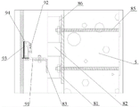
FIG. 2 is an enlarged view of a portion of FIG. 1A;
FIG. 3 is a schematic view of the connection between the specially-made dry hanging pieces and the horizontal and vertical keel system;
FIG. 4 is a schematic structural view of a specially-made dry hanging part;
FIG. 5 is a schematic view of a dry-hang element;
FIG. 6 is a schematic view of the connection of the metal composite wall surface with angle steel and square steel;
FIG. 7 is a schematic view of a female-corner closing-in member;
FIG. 8 is a schematic view of an external corner closing-in configuration;
FIG. 9 is a schematic view of a concave skirting line structure;
FIG. 10 is a first schematic view of a buffering structure of the flame retardant sheet;
FIG. 11 is a second schematic view of a buffering structure of the flame retardant sheet;
FIG. 12 is a schematic structural view of a wall surface decorated with LED lamps;
FIG. 13 is a schematic view of an LED light bar structure;
fig. 14 is a schematic view of a wall surface arrival lamp structure.
Reference numerals: 1-a metal composite plate; 2-a grid construction; 3-angle steel; 4-square steel; 5-structural wall body; 6-special metal fastener; 7-a metal hanging rod; 8-horizontal and vertical keel system; 81-galvanized buried plate; 82-channel steel main keel; 83-angle steel secondary keel; 84-expansion bolts; 85-opposite-penetrating screw; 86-galvanized angle steel; 9-specially-made dry hanging parts; 91-corner brace lower hanging piece; a 92-h-shaped upper hanger; 93-bolt type fastener; 931-upper clamping groove; 932-lower hollow platen; 933-press bridge; 934-Cross adjustment screw; 94-specially manufacturing bolt heads; 941-bolt head; 942-middle cis; 943-screw rod; 10-a rock plate; 11-ear pendant; 12-anchor bolt sleeve; 13-a disc; 14-a cushion tube; 15-lining; 151-first connection; 152-a second connection portion; 153-third connecting portion; 154-fourth connecting portion; 16-metal facing; 17-T type flame retardant plate lining; an 18-L-shaped metal facing; 19-square tube lining frame; a 20-T type flame retardant plate lining plate; 21-L type metal outer facing; 22-flame retardant board cushioning structure; 221-short angle steel; 222-a bottom flame retardant ply layer; 223-lateral flame retardant plate layer; 224-card board; 225-U-shaped metal sealing plates; 23-deformation resistant square steel; 24-lengthening channel steel; a 25-T shaped projection; 26-a LED light bar; 261-U type lamp cover; 262-strip trough body; 263-strip screw limit groove; 28-U-shaped base surface; 29-square steel tube; 30-acrylic sheet; 31-milk white yakeli tablet; 32-rectangular opening; 33-metal seal.
Detailed Description
In order to make the technical means, innovative features, objectives and functions realized by the present invention easy to understand, the present invention is further described below.
The examples described herein are specific embodiments of the present invention, are intended to be illustrative and exemplary in nature, and are not to be construed as limiting the scope of the invention. In addition to the embodiments described herein, those skilled in the art will be able to employ other technical solutions which are obvious based on the disclosure of the claims and the specification of the present application, and these technical solutions include technical solutions which make any obvious replacement or modification for the embodiments described herein.
A rock plate dry-hanging construction decoration system comprises a metal composite wall surface and a rock plate wall surface, wherein the metal composite wall surface comprises a metal composite plate 1, the outer side surface of the metal composite plate 1 is provided with a grid structure 2, the metal composite plate 1 comprises stainless steel metal panels at two sides and a middle flame-retardant plate, as shown in figure 6, the metal composite plate 1 is fixed with a structural wall body 5 through angle steel 3 and square steel 4, or is fixed with the structural wall body 5 through a transverse and longitudinal keel system 8 and a dry-hanging piece; the angle steel 3 is fixed with a structural wall 5 through expansion bolts at transverse intervals, the side plate surfaces of each angle steel 3 perpendicular to the wall surface are respectively provided with square steel 4 in a laminating manner, a stainless steel metal panel is fixed on the square steel 4, the grid structure 2 comprises a special metal clamping piece 6 fixed with the metal composite plate 1 through screws and a metal hanging rod 7 clamped and fixed on the special metal clamping piece 6, the special metal clamping piece 6 is of a convex structure, the metal hanging rod 7 is of a rectangular hollow rod-shaped structure with a strip-shaped opening on one side plate surface, the strip-shaped opening is a hanging port, and the plate surfaces on two sides of the hanging port are clamped and fixed on two sides of a protruding part of the convex structure and in a space between the stainless steel metal panel and the convex structure; as shown in fig. 5, the dry-hang element includes an ear-hang element 11 and an anchor bolt sleeve 12 extending from one side of the stainless steel metal panel and the middle flame-retardant plate and abutting against the other side of the stainless steel metal panel, the upper part of the ear-hang element 11 is hung and fixed on a side plate of the corner-code lower-hanging element 91 which is vertically arranged, the side wall is in threaded connection with the anchor bolt sleeve 12 through a bolt and a gasket, the anchor bolt sleeve 12 includes an internal thread cylinder and a disc 13 fixed on the stainless steel metal panel, barbs embedded into the middle flame-retardant plate are arranged around the disc 13 at intervals, and the dry-hang element and the special dry-hang element related to the application preferably adopt the stainless steel dry-hang element.
As shown in fig. 1, the rock plate wall surface comprises a rock plate 10 fixed with a structural wall body 5 through a transverse and longitudinal keel system 8 and a special dry hanging piece 9; the transverse and longitudinal keel system 8 comprises galvanized buried plates 81, channel steel main keels 82 vertically fixed on the upper and lower adjacent galvanized buried plates 81 and angle steel secondary keels 83 transversely fixed on the left and right adjacent channel steel main keels 82, the angle steel secondary keels 83 are back-welded or broken-welded and fixed with the channel steel main keels 82, the back-welding is that the angle steel secondary keels 83 are welded on the bottom surfaces of webs of the channel steel main keels 82, and the broken-welding is that the angle steel secondary keels 83 are welded on flange plates on two sides of the channel steel main keels 82 after being broken; galvanized angle steel 86 is fixed on the galvanized buried plate 81 and on two sides of the channel steel main keel 82 through expansion bolts 84 or opposite penetrating screws 85, notches of the two galvanized angle steel 86 are arranged in a reverse mode, and wing plates on two sides of the channel steel main keel 82 are attached to side plates of the galvanized angle steel 86 on two sides for fixing; as shown in fig. 3 and 4, the specially-made dry hanging piece 9 comprises a lower corner brace 91, an h-shaped upper brace 92 and a bolt type fastener 93 fixed on the rock plate 10, the bolt type fastener 93 is an integrally-formed structure with a rectangular outer outline of a vertical cross section and comprises an upper clamping groove 931, a lower hollow pressing plate 932 and a pressing bridge 933 for pressing and fixing the lower hollow pressing plate 932 on the rock plate 10, the lower corner brace 91 is bolted with an angle steel secondary keel 83, a bolt hole on the lower corner brace 91 is a horizontal strip bolt hole, a cross adjusting screw 934 is arranged at the transverse part of the upper h-shaped brace 92, a thread of the cross adjusting screw 934 passes through the transverse part, the end part is abutted against the top surface of a side plate of the lower corner brace 91, a left vertical plate of the upper h-shaped brace 92 is tightly attached to the bolt type fastener 93, the upper part of the left vertical plate is fixed with the upper clamping groove 931 through a specially-made bolt 94, the specially-made bolt 94 comprises a bolt head 941, a middle sequential smooth-insertion part 942 and a screw 943, the head 941 card of tying is fixed in upper portion draw-in groove 931, the head 941 cross-section of tying is isosceles trapezoid structure, the middle part is in the same direction as connecing portion 942 and is located the draw-in groove outlet, screw 943 passes left side riser upper portion and fixed through the nut, press bridge 933 includes the middle part connecting plate and locates middle part connecting plate both sides, the notch is towards the domes of slabstone 10, the middle part connecting plate is located lower part cavity clamp plate 932, both sides domes pass lower part cavity clamp plate 932 and pass through the bolt pressure solid on slabstone 10, bolt part inserts in the slabstone 10, bond through the colloid between bolt fastener 93 and the slabstone 10, it is fixed with slabstone 10 through dual fixed mode in other words to tie bolt fastener 93.
The rock plate wall surfaces at the internal corner and the external corner are all closed by a flame-retardant plate with the thickness of 18mm and a metal facing, as shown in fig. 7, wherein the internal corner closing-up member comprises a cushion tube 14, a lining 15 fixed on the cushion tube 14 and a metal facing 16 fixed on the outer side of the lining 15, the lining 15 is a rectangular notch formed by splicing the flame-retardant plates and comprises a first connecting part 151, a second connecting part 152, a third connecting part 153 and a fourth connecting part 154 which are sequentially connected, the first connecting part 151 and the third connecting part 153 are arranged in parallel and are connected with the second connecting part 152 to form a right angle, the third connecting part 153 is arranged perpendicular to the surface of the fourth connecting part 154, the metal facing 16 is attached to the inner wall of the rectangular notch, the cushion tube 14 is made of a galvanized square tube, and the lining 15 and the structural wall 5 are arranged at intervals; as shown in fig. 8, the external corner closing-in structure includes a T-shaped flame-retardant board lining 17 and an L-shaped metal facing 18 laid on the internal corner outside the T-shaped flame-retardant board lining 17, the T-shaped flame-retardant board lining 17 is fixed to an angle steel secondary keel 83 vertically arranged on both sides of the external corner, the horizontal cross section of the T-shaped flame-retardant board lining 17 is T-shaped, and metal panels such as the metal facing and the metal sealing plate of the present application all adopt stainless steel titanium plates.
As shown in fig. 9, an inward concave skirting line is further arranged between the wall surface of the rock slab and the floor, the inward concave skirting line comprises a square pipe lining frame 19 fixed on the structural wall 5, a T-shaped flame-retardant board lining board 20 and an L-shaped metal outer facing 21, two ends of a transverse portion of the T-shaped flame-retardant board lining board 20 are respectively abutted and fixed with the rock slab 10 and the square pipe lining frame 19, a top surface is abutted against a lower edge of a channel steel main keel 82, a vertical portion of the T-shaped flame-retardant board lining board 20 is erected on the floor, a transverse portion of the L-shaped metal outer facing 21 is laid on a transverse portion of the T-shaped flame-retardant board lining board 20 and a bottom surface of the rock slab 10, a vertical portion of the L-shaped metal outer facing 21 is laid on an outer side surface of a vertical portion of the T-shaped flame-retardant board lining board 20, and a vertical cross section of the T-shaped flame-retardant board lining board 20 is T-shaped.
As shown in fig. 10 and 11, the rock plate wall surface is further provided with flame retardant plate buffer structures 22 at intervals in the horizontal direction;
the whole flame retardant plate buffer structure 22 is U-shaped, and comprises short angle steel 221 fixed on the wall side of the angle steel secondary keel 83, a bottom flame retardant plate layer 222 fixed on the short angle steel 221 and lateral flame retardant plate layers 223 positioned on the two sides of the side face of the structural wall 5 far away from the bottom flame retardant plate layer 222, the lateral flame retardant plate layers 223 on the two sides and the bottom flame retardant plate layer 222 form a U-shaped groove body, two opposite side faces in the U-shaped groove body are respectively provided with a clamping plate 224, the clamping plate 224 is adhered to the lateral flame retardant plate layers 223 on the two sides through structural adhesive, a U-shaped metal sealing plate 225 is laid in the U-shaped groove body, the end parts of two vertical parts of the U-shaped metal sealing plate 225 are folded to form a clamping groove clamped on the upper edge of the clamping plate 224, and the end surfaces of the vertical parts on the two sides of the U-shaped metal sealing plate 225 are flush with the outer rock plates 10;
or the whole flame retardant plate buffer structure 22 is in an H shape, an H-shaped flame retardant plate lining and a U-shaped metal are used as an outer decorative surface, and anti-deformation square steel 23 is further fixed in a U-shaped space between the H-shaped flame retardant plate lining and the structural wall 5 and on the structural wall 5.
As shown in fig. 12, the wall surface is further provided with an LED lamp decorative wall surface, the galvanized angle steel 86 of the LED lamp decorative wall surface transverse longitudinal keel system 8 is replaced by a lengthened channel steel 24 which is vertically galvanized and embedded with a plate 81, the lengthened channel steel 24 makes the rock plate 10 and the transverse longitudinal keel system 8 protrude out of the rock plate at other positions, a T-shaped protrusion 25 is formed, two sides of the T-shaped vertical part of the T-shaped protrusion 25 are provided with LED light bars 26, as shown in fig. 13, each LED light bar 26 comprises a U-shaped light cover 261 and a strip groove 262 for receiving the light bars, two side walls of the U-shaped light cover 261 are buckled on the strip groove 262, a strip screw limiting groove 263 which is arranged along the strip groove 262 is arranged on the bottom plate of the strip groove 262, the length of the lengthened channel steel 24 is 500-800 mm, and the channel steel main keel 82 is fixed between the end flange plates of the two sides of the lengthened channel steel 24 far away from the structural wall 5.
As shown in fig. 14, a wall arrival lamp is arranged between the metal composite wall surface and the rock plate wall surface, between the adjacent metal composite wall surfaces, and between the adjacent rock plate wall surfaces, and the wall arrival lamp includes a U-shaped base surface 28 composed of flame retardant plates, the bottom surface of the U-shaped base surface 28 is fixed with the structural wall body 5, two sides of the U-shaped base surface are attached with square steel tubes 29 perpendicular to the wall surface, the square steel tubes 29 are attached to two sides of the U-shaped base surface 28 and fixed with two side transverse and longitudinal keel systems, the arrival lamp is fixed on the bottom surface of the U-shaped base surface 28, an outlet of the U-shaped base surface 28 is sealed by an acrylic plate 30, the acrylic plate 30 deviates from the side surface of the structural wall body 5, namely, the outer side surface is level with the outer surface of the metal hanging rod 7, and rectangular notches 32 are arranged on the two side or single side metal composite wall surfaces, and a milky acrylic sheet 31 is arranged on the side surface of the acrylic plate 30 close to the structural wall body 5.
As shown in fig. 1 and 2, the outer surface of the grid structure 2 is flush with the outer surface of the adjacent side rock plate 10, and a metal seal 33 is further arranged between the adjacent metal hanging rod 7 and the rock plate 10, wherein the metal seal 33 is a U-shaped steel member with a notch facing the structural wall 5, the thickness of the U-shaped steel member is 5mm, and the length of the U-shaped steel member is 18 mm.
The above description is only for the purpose of illustrating the preferred embodiments of the present invention and is not to be construed as limiting the invention, and any modifications, equivalents, improvements and the like that fall within the spirit and principle of the present invention are intended to be included therein.
Claims (8)
1. The utility model provides a rock plate is hung construction futilely and is decorated system, includes metal composite wall and rock plate wall, its characterized in that: the metal composite wall comprises a metal composite plate (1), a grid structure (2) is arranged on the outer side surface of the metal composite plate (1), the metal composite plate (1) comprises stainless steel metal panels on two sides and a middle flame-retardant plate, the metal composite plate (1) is fixed with a structural wall body (5) through angle steel (3) and square steel (4), or is fixed with the structural wall body (5) through a transverse and longitudinal keel system (8) and a dry hanging piece; the angle steel (3) is fixed with a structural wall body (5) through expansion bolts at transverse intervals, square steel (4) is attached to the surface of a side plate, perpendicular to the wall surface, of each angle steel (3), a stainless steel metal panel is fixed on each square steel (4), a grid structure (2) comprises a special metal clamping piece (6) fixed with a metal composite plate (1) through screws and a metal hanging rod (7) clamped on the special metal clamping piece (6), the special metal clamping piece (6) is of a convex structure, the metal hanging rod (7) is of a rectangular hollow rod-shaped structure with a strip-shaped opening on one side plate surface, the strip-shaped opening is a hanging port, and the plate surfaces on the two sides of the protruding portion of the convex structure and in the space between the stainless steel metal panel and the convex structure are clamped; the rock plate wall surface comprises a rock plate (10) which is fixed with a structural wall body (5) through a transverse and longitudinal keel system (8) and a special dry hanging piece (9); the transverse and longitudinal keel system (8) comprises galvanized buried plates (81), channel steel main keels (82) vertically fixed on the upper and lower adjacent galvanized buried plates (81) and angle steel secondary keels (83) transversely fixed on the left and right adjacent channel steel main keels (82), and the angle steel secondary keels (83) are welded with the channel steel main keels (82) in a back welding or broken welding mode; galvanized angle steel (86) is fixed on the galvanized buried plate (81) and on two sides of the channel steel main keel (82) through expansion bolts (84) or opposite-penetrating screws (85), notches of the two galvanized angle steel (86) are arranged oppositely, and wing plates on two sides of the channel steel main keel (82) are attached to side plates of the galvanized angle steel (86) on two sides for fixation; the specially-made dry hanging piece (9) comprises a corner code lower hanging piece (91), an h-shaped upper hanging piece (92) and a bolt type clamping piece (93) fixed on a rock plate (10), wherein the bolt type clamping piece (93) is an integrally-formed structure with a rectangular outer outline of a vertical cross section and comprises an upper clamping groove (931), a lower hollow pressing plate (932) and a pressing bridge (933) for pressing and fixing the lower hollow pressing plate (932) on the rock plate (10), the corner code lower hanging piece (91) is bolted with an angle steel secondary keel (83), an upper bolt hole of the corner code lower hanging piece (91) is a horizontal strip bolt hole, a cross adjusting screw (934) is arranged at the transverse part of the h-shaped upper hanging piece (92), the cross adjusting screw (934) penetrates through the transverse part in a threaded manner, the end of the cross adjusting screw abuts against the top surface of a side plate of the corner code lower hanging piece (91), a left side vertical plate of the h-shaped upper hanging piece (92) is tightly attached to the bolt type clamping piece (93), and the upper part of the left side plate is fixed with the upper clamping groove (931) through the specially-made bolt head (94), purpose-built bolt head (94) are in the same direction as connecing portion (942) and screw rod (943) including bolt head (941), the middle part that sets up in order, bolt head (941) card is fixed in upper portion draw-in groove (931), and the middle part is in the same direction as connecing portion (942) and is located the draw-in groove export, and screw rod (943) pass left side riser upper portion is fixed through the nut, press bridge (933) to include the middle part connecting plate and locate middle part connecting plate both sides, notch towards the domes of rock plate (10), the middle part connecting plate is located lower part cavity clamp plate (932), both sides arch passes lower part cavity clamp plate (932) and fixes in rock plate (10) through the bolt pressure.
2. The rock plate dry-hanging construction decoration system of claim 1, wherein: the dry hanging piece comprises an ear hanging piece (11) and an anchor bolt sleeve (12) which extends out of a stainless steel metal panel on one side and a middle flame-retardant plate and is abutted to the stainless steel metal panel on the other side, the upper portion of the ear hanging piece (11) is hung and fixed on a side plate which is vertically arranged on the lower corner brace hanging piece (91), the side wall is in threaded connection with the anchor bolt sleeve (12) through a bolt and a gasket, the anchor bolt sleeve (12) comprises an internal thread cylinder and a disc (13) fixed on the stainless steel metal panel, and barbs embedded into the middle flame-retardant plate are arranged around the disc (13) at intervals.
3. The rock plate dry-hanging construction decoration system of claim 1, wherein: the wall surfaces of the rock plates at the internal corner and the external corner are closed by a flame-retardant plate with the thickness of 18mm and a metal facing, wherein the internal corner closing-in component comprises a cushion tube (14), an inner lining (15) fixed on the cushion tube (14) and a metal facing (16) fixed on the outer side of the inner lining (15), the lining (15) is a rectangular gap formed by splicing flame-retardant plates and comprises a first connecting part (151), a second connecting part (152), a third connecting part (153) and a fourth connecting part (154) which are connected in sequence, the first connecting part (151) and the third connecting part (153) are arranged in parallel and are connected with the second connecting part (152) to form a right angle, the third connecting part (153) is perpendicular to the fourth connecting part (154), the metal veneer (16) is attached to the inner wall of the rectangular notch, and the cushion pipe (14) is made of a galvanized square pipe, so that the lining (15) and the structural wall (5) are arranged at intervals; the external corner closing-in structure comprises a T-shaped flame-retardant plate lining (17) and an L-shaped metal facing (18) paved on the internal corner of the outer side of the T-shaped flame-retardant plate lining (17), wherein the T-shaped flame-retardant plate lining (17) is fixed with angle steel secondary keels (83) which are arranged on two sides of an external corner in a mutually perpendicular mode.
4. The rock plate dry-hanging construction decoration system of claim 1, wherein: still be equipped with interior concave type skirting line between rock plate wall and the floor, interior concave type skirting line is including fixing square tube inside lining frame (19), the fire-retardant inboard welt of T type (20) and L type metal exterior finish (21) on structure wall body (5), the horizontal portion both ends of the fire-retardant inboard welt of T type (20) are fixed with rock plate (10) and square tube inside lining frame (19) butt respectively, and the butt is followed down along butt under top surface and channel-section steel main joist (82), and the perpendicular portion of the fire-retardant inboard welt of T type (20) stands on the floor, L type metal exterior finish (21) horizontal portion is spread and is pasted at the fire-retardant inboard welt of T type (20) horizontal portion and rock plate (10) bottom surface, and L type metal exterior finish (21) are erected the portion and are spread and paste at the fire-retardant inboard welt of T type (20) outside surface of vertical portion.
5. The rock plate dry-hanging construction decoration system of claim 1, wherein: flame retardant plate buffer structures (22) are horizontally arranged on the rock plate wall surface at intervals;
the flame retardant plate buffer structure (22) is integrally U-shaped and comprises short angle steel (221) fixed on the wall side of an angle steel secondary keel (83), a bottom flame retardant plate layer (222) fixed on the short angle steel (221) and lateral flame retardant plate layers (223) located on the bottom flame retardant plate layer (222) and far away from the two sides of the side face of the structure wall body (5), the lateral flame retardant plate layers (223) on the two sides and the bottom flame retardant plate layer (222) form a U-shaped groove body, two opposite side faces in the U-shaped groove body are respectively provided with a clamping plate (224), the clamping plates (224) are fixedly adhered to the lateral flame retardant plate layers (223) on the two sides through structural adhesive, a U-shaped metal sealing plate (225) is laid in the U-shaped groove body, the end parts of two vertical parts of the U-shaped metal sealing plate (225) are folded to form a clamping groove clamped on the upper edge of the clamping plates (224), and the end surfaces of the vertical parts on the two sides of the U-shaped metal sealing plate (225) are flush with the outer rock plate (10);
or the whole flame retardant plate buffer structure (22) is H-shaped, an H-shaped flame retardant plate lining is used, U-shaped metal is used as an outer facing, and anti-deformation square steel (23) is further fixed in a U-shaped space between the H-shaped flame retardant plate lining and the structural wall body (5) and on the structural wall body (5).
6. The rock plate dry-hanging construction decoration system of claim 1, wherein: the LED lamp decorative wall surface is further arranged on the rock plate wall surface, galvanized angle steel (86) on the LED lamp decorative wall surface is replaced by lengthened channel steel (24) arranged on the vertical galvanized buried plate (81), the rock plate (10) and the transverse and longitudinal keel system protrude to form a T-shaped protruding part (25) through the lengthened channel steel (24), two sides of the T-shaped vertical part of the T-shaped protruding part (25) are provided with LED lamp strips (26), each LED lamp strip (26) comprises a U-shaped lamp cover (261) and a strip-shaped groove body (262) used for bearing the lamp strip, two side walls of the U-shaped lamp cover (261) are buckled on the strip-shaped groove bodies (262), a strip screw limiting groove (263) which is arranged along the whole length of the strip groove body (262) is arranged on the bottom plate of the strip groove body (262), the length of the lengthened channel steel (24) ranges from 500 mm to 800mm, and the channel steel main keels (82) are fixed between end flange plates of the lengthened channel steel (24) on the two sides, far away from the structural wall (5).
7. The rock plate dry-hanging construction decoration system of claim 1, wherein: wall surface arrival lamps are arranged between the metal composite wall surfaces and the rock plate wall surfaces, between the adjacent metal composite wall surfaces and between the adjacent rock plate wall surfaces, each wall surface arrival lamp comprises a U-shaped base surface (28) consisting of flame retardant plates, the bottom surface of the U-shaped base surface (28) is fixed with the structural wall body (5), square steel pipes (29) vertical to the wall surface are attached to the two sides of the U-shaped base surface (28), the square steel pipes (29) are attached to the two sides of the U-shaped base surface (28), and is fixed with the transverse and longitudinal keel systems at two sides, the arrival lamp is fixed on the bottom surface of the U-shaped base surface (28), the outlet of the U-shaped base surface (28) is sealed by an acrylic plate (30), the side surface of the acrylic plate (30) departing from the structural wall body (5) is level with the outer surface of the metal hanging rod (7), rectangular openings (32) are arranged on the metal composite wall surfaces on two sides or one side, and milky acrylic sheets (31) are arranged on the side surfaces of the acrylic plates (30) close to the structural wall body (5).
8. The rock plate dry-hanging construction decoration system of claim 1, wherein: the utility model discloses a grid structure, including grid structure (2), adjacent side rock plate (10), metal seal strip (33) are U shaped steel component, and thickness is 5mm, and length is 18mm that the surface of grid structure (2) is equal with adjacent side rock plate (10) surface, and still is equipped with between adjacent metal peg (7) and rock plate (10), metal seal strip (33) are the notch towards structure wall body (5).
Priority Applications (1)
| Application Number | Priority Date | Filing Date | Title |
|---|---|---|---|
| CN202210514702.6A CN114837365B (en) | 2022-05-12 | 2022-05-12 | Rock plate dry-hanging construction decoration system |
Applications Claiming Priority (1)
| Application Number | Priority Date | Filing Date | Title |
|---|---|---|---|
| CN202210514702.6A CN114837365B (en) | 2022-05-12 | 2022-05-12 | Rock plate dry-hanging construction decoration system |
Publications (2)
| Publication Number | Publication Date |
|---|---|
| CN114837365A true CN114837365A (en) | 2022-08-02 |
| CN114837365B CN114837365B (en) | 2023-10-03 |
Family
ID=82570505
Family Applications (1)
| Application Number | Title | Priority Date | Filing Date |
|---|---|---|---|
| CN202210514702.6A Active CN114837365B (en) | 2022-05-12 | 2022-05-12 | Rock plate dry-hanging construction decoration system |
Country Status (1)
| Country | Link |
|---|---|
| CN (1) | CN114837365B (en) |
Citations (19)
| Publication number | Priority date | Publication date | Assignee | Title |
|---|---|---|---|---|
| JPH08144467A (en) * | 1994-11-17 | 1996-06-04 | Showa Denko Kenzai Kk | Fitting method of stony plate |
| JP2000220236A (en) * | 1999-01-29 | 2000-08-08 | Takiron Co Ltd | Wall surface protecting structure |
| RU2010114729A (en) * | 2010-04-14 | 2011-10-20 | Общество с ограниченной ответственностью "ОЛМА" (RU) | CLAMMER FOR FIXING FACING BOARDS |
| CN102383508A (en) * | 2011-09-20 | 2012-03-21 | 沈阳远大铝业工程有限公司 | Split clamping and fixing type ceramic tile curtain wall |
| CN102828601A (en) * | 2012-09-18 | 2012-12-19 | 苏州苏明装饰有限公司 | Wood veneer hanging and mounting system |
| CN103306389A (en) * | 2013-07-04 | 2013-09-18 | 许浒 | Dry-hang external wall insulation board and novel application thereof as dismounting-free building template |
| KR20140137273A (en) * | 2013-05-22 | 2014-12-02 | 주종복 | Combination Structure of Panel for External of Building and Method for Constructing thereof |
| CN206769146U (en) * | 2017-05-20 | 2017-12-19 | 江苏建设控股集团有限公司 | A kind of back-bolt type stone curtain wall |
| CN110259021A (en) * | 2019-06-14 | 2019-09-20 | 苏州金螳螂建筑装饰股份有限公司 | A kind of rock beam hanger structure |
| CN111287355A (en) * | 2020-02-17 | 2020-06-16 | 温州锐翔装饰工程有限公司 | Glass curtain wall protrusion stand system of decorating |
| CN211058218U (en) * | 2019-10-29 | 2020-07-21 | 丁善雪 | Aluminum profile mounting keel frame for laying wall porcelain plate |
| CN212836384U (en) * | 2020-07-08 | 2021-03-30 | 中建二局装饰工程有限公司 | Mounting structure of porcelain aluminum plate |
| CN113006353A (en) * | 2021-02-21 | 2021-06-22 | 浙江建设职业技术学院 | Construction method of prefabricated hanging plate curtain wall |
| CN214090744U (en) * | 2020-12-01 | 2021-08-31 | 佛山仙璧建筑材料有限公司 | Hanging device for improving rock plate connecting structure |
| EP3892792A1 (en) * | 2018-12-07 | 2021-10-13 | Zhong, Bing | Artificial cement-based ultra-high-performance stone slab |
| CN215631256U (en) * | 2021-06-21 | 2022-01-25 | 佛山市石力派建筑工程有限公司 | Novel dry-hanging assembly for rock plate |
| CN114197781A (en) * | 2021-12-10 | 2022-03-18 | 浙江亚厦装饰股份有限公司 | Mounting structure of assembled tectorial membrane wallboard |
| CN216195389U (en) * | 2021-10-26 | 2022-04-05 | 中建二局装饰工程有限公司 | Aluminum plate decorative structure of view ring corridor |
| CN217400166U (en) * | 2022-05-12 | 2022-09-09 | 中建二局装饰工程有限公司 | Outer wall decoration system |
-
2022
- 2022-05-12 CN CN202210514702.6A patent/CN114837365B/en active Active
Patent Citations (19)
| Publication number | Priority date | Publication date | Assignee | Title |
|---|---|---|---|---|
| JPH08144467A (en) * | 1994-11-17 | 1996-06-04 | Showa Denko Kenzai Kk | Fitting method of stony plate |
| JP2000220236A (en) * | 1999-01-29 | 2000-08-08 | Takiron Co Ltd | Wall surface protecting structure |
| RU2010114729A (en) * | 2010-04-14 | 2011-10-20 | Общество с ограниченной ответственностью "ОЛМА" (RU) | CLAMMER FOR FIXING FACING BOARDS |
| CN102383508A (en) * | 2011-09-20 | 2012-03-21 | 沈阳远大铝业工程有限公司 | Split clamping and fixing type ceramic tile curtain wall |
| CN102828601A (en) * | 2012-09-18 | 2012-12-19 | 苏州苏明装饰有限公司 | Wood veneer hanging and mounting system |
| KR20140137273A (en) * | 2013-05-22 | 2014-12-02 | 주종복 | Combination Structure of Panel for External of Building and Method for Constructing thereof |
| CN103306389A (en) * | 2013-07-04 | 2013-09-18 | 许浒 | Dry-hang external wall insulation board and novel application thereof as dismounting-free building template |
| CN206769146U (en) * | 2017-05-20 | 2017-12-19 | 江苏建设控股集团有限公司 | A kind of back-bolt type stone curtain wall |
| EP3892792A1 (en) * | 2018-12-07 | 2021-10-13 | Zhong, Bing | Artificial cement-based ultra-high-performance stone slab |
| CN110259021A (en) * | 2019-06-14 | 2019-09-20 | 苏州金螳螂建筑装饰股份有限公司 | A kind of rock beam hanger structure |
| CN211058218U (en) * | 2019-10-29 | 2020-07-21 | 丁善雪 | Aluminum profile mounting keel frame for laying wall porcelain plate |
| CN111287355A (en) * | 2020-02-17 | 2020-06-16 | 温州锐翔装饰工程有限公司 | Glass curtain wall protrusion stand system of decorating |
| CN212836384U (en) * | 2020-07-08 | 2021-03-30 | 中建二局装饰工程有限公司 | Mounting structure of porcelain aluminum plate |
| CN214090744U (en) * | 2020-12-01 | 2021-08-31 | 佛山仙璧建筑材料有限公司 | Hanging device for improving rock plate connecting structure |
| CN113006353A (en) * | 2021-02-21 | 2021-06-22 | 浙江建设职业技术学院 | Construction method of prefabricated hanging plate curtain wall |
| CN215631256U (en) * | 2021-06-21 | 2022-01-25 | 佛山市石力派建筑工程有限公司 | Novel dry-hanging assembly for rock plate |
| CN216195389U (en) * | 2021-10-26 | 2022-04-05 | 中建二局装饰工程有限公司 | Aluminum plate decorative structure of view ring corridor |
| CN114197781A (en) * | 2021-12-10 | 2022-03-18 | 浙江亚厦装饰股份有限公司 | Mounting structure of assembled tectorial membrane wallboard |
| CN217400166U (en) * | 2022-05-12 | 2022-09-09 | 中建二局装饰工程有限公司 | Outer wall decoration system |
Non-Patent Citations (4)
| Title |
|---|
| FEIYANG WANG: "《A mesostructure-informed cohesion-based numerical method for fracture behavior of slate with foliation structure》", 《INTERNATIONAL JOURNAL OF ROCK MECHANICS AND MINING SCIENCES》 * |
| 佟克龙;侯磊;: "组焊箱型钢柱玻璃幕墙设计施工技术及其应用", 山西建筑, no. 05 * |
| 陈民,杜志豪: "支架片接式石材幕墙设计方法和施工", 石材, no. 02 * |
| 龚昌基: "玻璃幕墙结构设计若干问题的探讨", 建筑结构, no. 02 * |
Also Published As
| Publication number | Publication date |
|---|---|
| CN114837365B (en) | 2023-10-03 |
Similar Documents
| Publication | Publication Date | Title |
|---|---|---|
| CN201901997U (en) | Fastening component, curtain wall system, hollow glass unit and glass assembling component | |
| CN107044179B (en) | Decorative panel and template integrated heat-preservation decorative composite wall and construction method thereof | |
| WO2017173656A1 (en) | Assembled building structure | |
| CN217400166U (en) | Outer wall decoration system | |
| CN108894456B (en) | Prefabricated foaming ceramic frame exterior wall cladding and manufacturing method thereof | |
| CN110469075B (en) | Wall ceramic aluminum core absorbing soundboard system and construction method thereof | |
| CN115977258A (en) | ALC wallboard and girder steel and concrete floor joint construction | |
| CN110130546A (en) | A kind of assembled anti-knock internal partition wall and its installation method | |
| CN214833751U (en) | Double-layer composite inner wallboard and inner wall enclosure system | |
| CN212957024U (en) | Prefabricated steel structure integrated assembly type green building component | |
| CN114837365A (en) | Rock plate dry-hanging construction decoration system | |
| CN217461256U (en) | Outer facing construction node of rock plate and metal composite board handing-over department wall body | |
| CN217461033U (en) | Composite wall panel mounting structure for modular substation | |
| CN217400168U (en) | Use molding wall of rock plate as decoration material | |
| CN217461258U (en) | Wall exterior finish | |
| CN214461591U (en) | Assembled peripheral wall panel of steel structural framework | |
| CN116025073A (en) | Waterproof device for building separation structure seam of high-speed rail station building bridge and construction method | |
| CN217461257U (en) | External decorative surface of metal composite board | |
| CN217400206U (en) | Dry pendant of rock plate | |
| CN217400205U (en) | Indoor decoration structure with flame-retardant plate as closing material | |
| CN217400167U (en) | Wall lamp construction structures that arrives at a station | |
| CN110453823B (en) | Light steel keel partition wall free of auxiliary keel and mounting method thereof | |
| CN111809779B (en) | Stably-installed building curtain wall structure | |
| CN208594653U (en) | A kind of assembled anti-knock internal partition wall | |
| CN109138242B (en) | Fireproof curtain wall |
Legal Events
| Date | Code | Title | Description |
|---|---|---|---|
| PB01 | Publication | ||
| PB01 | Publication | ||
| SE01 | Entry into force of request for substantive examination | ||
| SE01 | Entry into force of request for substantive examination | ||
| GR01 | Patent grant | ||
| GR01 | Patent grant |