CN114829812A - Connection structure for connecting conduction port and pipe end, opening/closing valve device, and method for removing seal member - Google Patents
Connection structure for connecting conduction port and pipe end, opening/closing valve device, and method for removing seal member Download PDFInfo
- Publication number
- CN114829812A CN114829812A CN202080087975.6A CN202080087975A CN114829812A CN 114829812 A CN114829812 A CN 114829812A CN 202080087975 A CN202080087975 A CN 202080087975A CN 114829812 A CN114829812 A CN 114829812A
- Authority
- CN
- China
- Prior art keywords
- opening
- flow path
- seal member
- pipe
- valve device
- Prior art date
- Legal status (The legal status is an assumption and is not a legal conclusion. Google has not performed a legal analysis and makes no representation as to the accuracy of the status listed.)
- Pending
Links
Images


Classifications
-
- B—PERFORMING OPERATIONS; TRANSPORTING
- B25—HAND TOOLS; PORTABLE POWER-DRIVEN TOOLS; MANIPULATORS
- B25B—TOOLS OR BENCH DEVICES NOT OTHERWISE PROVIDED FOR, FOR FASTENING, CONNECTING, DISENGAGING OR HOLDING
- B25B27/00—Hand tools, specially adapted for fitting together or separating parts or objects whether or not involving some deformation, not otherwise provided for
- B25B27/14—Hand tools, specially adapted for fitting together or separating parts or objects whether or not involving some deformation, not otherwise provided for for assembling objects other than by press fit or detaching same
-
- F—MECHANICAL ENGINEERING; LIGHTING; HEATING; WEAPONS; BLASTING
- F16—ENGINEERING ELEMENTS AND UNITS; GENERAL MEASURES FOR PRODUCING AND MAINTAINING EFFECTIVE FUNCTIONING OF MACHINES OR INSTALLATIONS; THERMAL INSULATION IN GENERAL
- F16J—PISTONS; CYLINDERS; SEALINGS
- F16J15/00—Sealings
-
- F—MECHANICAL ENGINEERING; LIGHTING; HEATING; WEAPONS; BLASTING
- F16—ENGINEERING ELEMENTS AND UNITS; GENERAL MEASURES FOR PRODUCING AND MAINTAINING EFFECTIVE FUNCTIONING OF MACHINES OR INSTALLATIONS; THERMAL INSULATION IN GENERAL
- F16J—PISTONS; CYLINDERS; SEALINGS
- F16J15/00—Sealings
- F16J15/02—Sealings between relatively-stationary surfaces
- F16J15/06—Sealings between relatively-stationary surfaces with solid packing compressed between sealing surfaces
- F16J15/10—Sealings between relatively-stationary surfaces with solid packing compressed between sealing surfaces with non-metallic packing
-
- F—MECHANICAL ENGINEERING; LIGHTING; HEATING; WEAPONS; BLASTING
- F16—ENGINEERING ELEMENTS AND UNITS; GENERAL MEASURES FOR PRODUCING AND MAINTAINING EFFECTIVE FUNCTIONING OF MACHINES OR INSTALLATIONS; THERMAL INSULATION IN GENERAL
- F16L—PIPES; JOINTS OR FITTINGS FOR PIPES; SUPPORTS FOR PIPES, CABLES OR PROTECTIVE TUBING; MEANS FOR THERMAL INSULATION IN GENERAL
- F16L19/00—Joints in which sealing surfaces are pressed together by means of a member, e.g. a swivel nut, screwed on or into one of the joint parts
- F16L19/02—Pipe ends provided with collars or flanges, integral with the pipe or not, pressed together by a screwed member
- F16L19/0212—Pipe ends provided with collars or flanges, integral with the pipe or not, pressed together by a screwed member using specially adapted sealing means
Abstract
An object of the present invention is to provide a connection structure, an opening/closing valve device, and a method of removing a seal member, which can easily replace a seal member that can be disposed at an appropriate position in a connected state between a conduction port and a pipe end portion and which connects the conduction port and the pipe end portion. In a connection structure (X) between a conduction port (12) of a container valve device (1) and a pipe end (102) of a flow path pipe (100), the conduction port and the pipe end are arranged in a butt joint manner, and an annular gasket (20) is arranged between the conduction port and the pipe end, the gasket is provided with an opening (21) through which a roughly columnar insertion front end (203) of a dismounting jig (200) can be inserted, an installation groove (122) for installing the gasket is formed in the conduction port, and a taper space (123) is arranged on a main body side (B) in an installation state of installing the gasket in the installation groove, and the taper space prevents the insertion front end from interfering when the dismounting jig with the insertion front end is inclined when the dismounting jig with the insertion front end inserted into the opening for dismounting the gasket.
Description
Technical Field
The present invention relates to a connection structure for connecting a conduction port, which is one end of a flow path, to a pipe end of a flow path pipe for conducting a fluid, in an opening/closing valve device having an opening/closing valve for switching opening/closing at an intermediate portion of the flow path for conducting the gas, for example, and relates to the opening/closing valve device, and a method for detaching a seal member attached to the opening/closing valve device.
Background
In general, an opening/closing valve device having an opening/closing valve that switches between an open state and a sealed state connects a conduit, which is one end of a flow path, to a pipe end of a flow path pipe to allow fluid such as gas to flow therethrough. At this time, as shown in patent document 1, an annular seal member (gasket) is disposed between the introduction port and the pipe end portion to prevent gas from leaking from a joint portion between the introduction port and the pipe end portion.
Such a sealing member is mounted in a pressurized state in order to obtain high sealing performance, and therefore, it may deteriorate due to use, and the sealing performance may be lowered. In this way, the sealing member having lowered sealing performance loosens the connection between the conduction port and the pipe end and needs to be replaced. In particular, when a gas having a high risk of leakage, such as a highly corrosive gas, is conducted, the gas to be conducted may be replaced with a sealing member every time the gas is used.
However, as shown in patent document 1, in the case where the seal member is attached to the attachment groove (step portion), the seal member can be disposed at an appropriate position as compared with the case where only the seal member is disposed at the joint portion.
Documents of the prior art
Patent literature
Patent document 1: japanese patent laid-open publication No. 2003-74798
Disclosure of Invention
Problems to be solved by the invention
Therefore, an object of the present invention is to provide a connection structure, an opening/closing valve device, and a method of removing a seal member, which can easily replace a seal member that can be disposed at an appropriate position in a connected state between a conduction port and a pipe end portion and connect the conduction port and the pipe end portion.
Means for solving the problems
The present invention is a connection structure for connecting a conduit, which is one end of a flow path pipe for conducting a fluid, to a pipe end of the flow path pipe, the conduit being provided with an opening/closing valve for switching between open and closed states at a middle portion of the flow path for conducting the fluid, wherein the conduit is disposed in abutment with the pipe end, and an annular seal member having an opening through which a substantially columnar insertion tip portion of a removable jig can be inserted is disposed between the conduit and the pipe end, an attachment groove for attaching the seal member is formed in at least one of the conduit and the pipe end, and an interference prevention space is provided on a back surface side opposite to a side opposite to the other of the conduit and the pipe end in an attached state in which the seal member is attached to the attachment groove, the interference prevention space prevents interference with the insertion tip portion when the removal jig, which inserts the insertion tip portion into the opening, is tilted in order to remove the seal member.
The opening/closing valve device of the present invention is characterized in that the opening/closing valve device has an opening/closing valve for switching opening/closing in an intermediate portion of a flow path through which fluid is conducted, one end of the flow path is used as a conduction port which is connected with the end part of the flow path pipe for conducting the fluid in a butt joint way, an installation groove is arranged on the conduction port, the mounting groove is provided with an annular sealing component which is provided with an opening for the approximately columnar insertion front end part of the disassembling jig to penetrate and insert, an interference prevention space is provided on a back surface side opposite to a side opposite to the pipe end in an attached state in which the seal member is attached to the attachment groove, the interference prevention space prevents interference with the insertion tip portion when the removal jig, which inserts the insertion tip portion into the opening, is tilted in order to remove the seal member.
The fluid may be a gas, a liquid, or a gel, or may be a fluid having a high risk due to leakage, such as a corrosive gas having high corrosiveness.
The sealing member is a member having sealing properties and elasticity, such as an O-ring, a rubber packing, or a metal packing, and is also called a gasket.
The opening/closing valve device may be a container valve device that is attached to a container such as a gas cylinder to restrict the entry and exit of fluid, or a piping valve device that is attached between flow piping to restrict the conduction of fluid flowing through the flow piping.
The direction of conduction of the fluid to be conducted may be one direction from one of the flow path in the valve device having the conduction port at one end and the flow path pipe having the pipe end portion to the other, or may be two directions in which the direction of conduction is changed depending on the purpose of conduction, such as filling and discharging.
The mounting groove formed in at least one of the passage opening and the pipe end portion may be a mounting groove formed in the passage opening, a mounting groove formed in the pipe end portion, or a mounting groove formed in both the passage opening and the pipe end portion.
In addition, the mounting groove formed in both the conduction port and the pipe end portion may be a groove in which the sealing member is mounted to one of mounting grooves formed in the same shape and the sealing member is fitted to the other mounting groove in a connected state, or a groove in which the sealing member is fitted to the other sub-mounting groove in a connected state with the one mounting groove as a main mounting groove.
In the mounting state in which the seal member is mounted in the mounting groove, an interference prevention space for preventing interference with the insertion tip portion that is inserted through the opening and moved to remove the seal member may be formed on a back surface side opposite to a side opposite to the other of the conduction port and the pipe end portion, in a circumferential direction, or may be formed in a part of the circumferential direction, or may be formed in a plurality of portions. Further, the space may be formed on the back side of the opening formed with a small diameter with respect to the flow path with a large diameter.
According to the present invention, the sealing member which can be disposed at an appropriate position in a connected state between the conduction port and the pipe end can be easily removed and replaced.
In detail, in a connection structure in which a conduction port, which is one end of a flow path in a valve opening and closing device having a valve for switching opening and closing in an intermediate portion of the flow path through which a fluid is conducted, is butted against a pipe end portion of a flow path pipe through which the fluid is conducted, a seal member disposed between the conduction port and the pipe end portion is attached to an attachment groove formed in at least one of the conduction port and the pipe end portion, whereby the seal member can be reliably disposed at an appropriate position.
Further, by providing the interference prevention space on the back surface side opposite to the other of the conduction port and the pipe fitting end portion in the attached state in which the sealing member is attached to the attachment groove, and tilting the removal jig with the insertion tip portion inserted into the opening to remove the sealing member attached to the attachment groove, and applying a force to the sealing member toward the side opposite to the back surface side, the sealing member attached to the attachment groove can be easily removed and replaced without interference of the substantially columnar insertion tip portion of the removal jig.
Therefore, even when corrosive gas or the like is conducted such that the sealing member is replaced every time the sealing member is used, the sealing member can be replaced easily and efficiently, and the sealing member can be used safely.
Further, since the insertion tip portion is inserted into the opening portion, the detached seal member is fitted to the insertion tip portion, and the seal member can be prevented from being scattered and lost, for example.
In an aspect of the present invention, the mounting groove and the interference preventing space may be formed in the conduction port.
According to the present invention, the replaceability of the seal member can be improved.
In detail, compared with the case where the mounting groove and the interference prevention space are provided at the pipe end of the fixed flow path pipe, the mounting groove and the interference prevention space are provided at the conduction port of the opening/closing valve device which is easily detached or moved, so that the seal member attached to the mounting groove can be easily detached, and the replaceability of the seal member can be improved.
In the aspect of the present invention, the mounting groove may have a contact surface that contacts the seal member with a predetermined pressure receiving area, and the interference preventing space may be provided on the back surface side and on a radial inner side of the mounting groove to which the seal member is mounted.
According to the present invention, in the state where the conduction port and the pipe end are connected, the sealing member attached to the attachment groove can be reliably sealed, and the sealing member attached to the attachment groove can be removed by the removal jig.
Specifically, since the mounting groove has a contact surface that contacts the seal member with a predetermined pressure receiving area, the seal member can be pressurized and reliably sealed without being unexpectedly deformed in the connected state.
Further, since the interference preventing space is provided on the back surface side and on the radial inner side of the mounting groove to which the seal member is mounted, the interference preventing space having a small influence on the flow of the fluid to be conducted can be configured with a simple structure.
Further, the present invention is a method of removing a seal member, in a connection structure in which a conduit, which is one end of a fluid passage, in an opening and closing valve device having an opening and closing valve for switching opening and closing in an intermediate portion of the fluid passage to be communicated with a fluid passage, and a pipe end portion of a fluid passage pipe to be communicated with the fluid are connected, the method comprising removing the seal member mounted in a mounting groove formed in at least one of the conduit and the pipe end portion, wherein an interference prevention space is provided on a back surface side opposite to a side opposite to the other of the conduit and the pipe end portion in a mounted state in which the seal member is mounted in the mounting groove, the interference prevention space preventing the insertion tip portion from interfering with an insertion tip portion when a removal jig, which is inserted into an opening in order to remove the seal member, is tilted, and inserting the insertion tip portion into the opening of the seal member mounted in the mounting groove The removal jig in (1) is inclined with respect to the insertion direction to remove the sealing member from the mounting groove.
According to the present invention, the sealing member is attached to the attachment groove formed in at least one of the introduction port and the pipe end portion, whereby the sealing member can be disposed at an appropriate position in a state where the introduction port and the pipe end portion are connected to each other.
Further, by providing the interference preventing space on the back surface side which is the opposite side to the other of the conduction port and the pipe fitting end portion in the attached state in which the sealing member is attached to the attachment groove, and tilting the detachment jig with the insertion tip portion inserted into the opening in order to detach the sealing member attached to the attachment groove, and applying a force to the sealing member toward the side opposite to the back surface side, the sealing member attached to the attachment groove can be easily detached and replaced without interference of the substantially columnar insertion tip portion of the detachment jig. Therefore, even when corrosive gas or the like is conducted such that the sealing member is replaced every time the sealing member is used, the sealing member can be replaced easily and efficiently, and the sealing member can be used safely.
In an aspect of the present invention, the removal jig may be inclined after the insertion tip portion is inserted into the opening until an excessive insertion prevention unit that prevents the insertion tip portion from being excessively inserted into the opening functions.
According to the present invention, it is possible to prevent the occurrence of a problem that the insertion tip portion is excessively inserted, for example, the insertion tip portion is inserted into the flow path and cannot be inclined for detaching the sealing member attached to the attachment groove, and the sealing member cannot be detached, or a problem that the insertion amount of the insertion tip portion into the opening is excessively small (hereinafter, referred to as excessively small insertion), and the insertion tip portion cannot be separated from the opening and cannot be detached for detaching the sealing member even if the insertion tip portion is inclined for detaching the sealing member attached to the attachment groove.
In the above-described aspect of the present invention, the excessive insertion preventing means may be an indicating means that is provided at a proximal end portion of the insertion distal end portion of the removal jig and indicates an excessive insertion position, and the indicating means may be inserted until the position is located at an edge portion of the opening.
According to the present invention, it is possible to prevent the over-insertion or the under-insertion of the insertion tip portion by visual observation, and to reliably remove the seal member.
In the above-described aspect of the present invention, the excessive insertion prevention means may be an abutment restriction portion that is provided at a proximal end portion of the insertion distal end portion of the removal jig and that, when inserted to an excessive insertion position, abuts against an edge portion of the opening to restrict the excessive insertion, and the abutment restriction portion may be inserted until the excessive insertion is abutted against the edge portion of the opening.
According to the present invention, the insertion position can be restricted by the abutment restricting portion, so that the seal member can be reliably removed by preventing the insertion tip portion from being excessively inserted or excessively inserted.
In an aspect of the present invention, the insertion tip portion that can be inserted into the opening may be formed in a non-insertion shape that cannot be inserted into one end of the flow path, and the insertion tip portion formed in the non-insertion shape may function as the over-insertion preventing means.
According to the present invention, the insertion position can be restricted by the flow path, and the seal member can be reliably removed by preventing the insertion tip portion from being excessively inserted or excessively inserted.
The non-insertion shape may be a cross-sectional circle having a large diameter with respect to a flow path having a circular cross-section, a cross-sectional ellipse having a long diameter, a cross-sectional shape in which at least a part of the circumferential direction in the end face of the insertion tip portion protrudes in the radial direction, or the like.
Effects of the invention
According to the present invention, it is possible to provide a connection structure, an opening/closing valve device, and a method of removing a seal member, which can easily replace a seal member that can be arranged at an appropriate position in a state where an introduction port and a pipe end are connected, and which can connect the introduction port and the pipe end.
Drawings
Fig. 1 is a partially sectional schematic front view of a connection structure between a container valve device and a flow path pipe.
Fig. 2 is a partially sectional schematic explanatory view of a connection structure between the container valve device and the flow path pipe.
Fig. 3 is a partially sectional schematic front view of a connection structure between the container valve device and the flow path pipe.
Fig. 4 is a partially sectional schematic front view of a connection structure between the container valve device and the flow path pipe.
Fig. 5 is a partially sectional schematic perspective view of a connection structure between the container valve device and the flow path pipe.
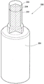
Fig. 6 is a perspective view of the removal jig.
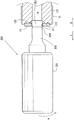
Fig. 7 is a partially sectional schematic front view showing a state where the removal jig is inserted into a gasket attached to a conduction port of the container valve device.
Fig. 8 is an explanatory diagram of a state in which the removal jig is removed by the gasket attached to the conduction port of the container valve device.
Fig. 9 is a partially sectional schematic front view of a connection structure between a piping valve device and a flow path piping.
Fig. 10 is a partially sectional schematic explanatory view of a connection structure between the piping valve device and the flow path piping.
Fig. 11 is a partially sectional schematic front view of a connection structure between a piping valve device and a flow path piping.
Fig. 12 is a partially sectional schematic front view of a connection structure between a piping valve device and a flow path piping.
Fig. 13 is a perspective view of a detachment jig according to another embodiment.
Fig. 14 is an explanatory diagram of a state in which the removal jig is removed based on the gasket attached to the conduction port of the piping valve device.
Fig. 15 is an explanatory diagram of a state in which the removal jig is removed based on the gasket attached to the conduction port of the piping valve device.
Fig. 16 is a partially cross-sectional explanatory view of a connection structure between a conduction port and a flow path pipe according to another embodiment.
Detailed Description
A connection structure X between the container valve device 1 and the flow path pipe 100 and removal of the gasket 20 attached to the attachment groove 122 according to one embodiment of the present invention will be described with reference to fig. 1 to 8.
Fig. 1, 3, and 4 show a partially sectional schematic front view of a connection structure X of the container valve device 1 and the flow path pipe 100, fig. 2 shows a partially sectional schematic explanatory view of a connection structure X of the conduction port 12 of the container valve device 1 and the flow path pipe 100, fig. 5 shows a partially sectional schematic perspective view of a connection structure X of the conduction port 12 of the container valve device 1 and the flow path pipe 100, fig. 6 shows a perspective view of the removal jig 200, fig. 7 shows a partially sectional schematic front view of a state in which the support column portion 202 of the removal jig 200 is inserted into the gasket 20 attached to the conduction port 12 of the container valve device 1, and fig. 8 shows an explanatory view of a state in which the removal jig 200 is detached based on the gasket 20 attached to the conduction port 12 of the container valve device 1.
In detail, fig. 1 shows a partially sectional schematic front view of the connection structure X in an exploded state, fig. 2 shows a partially sectional schematic front view of the connection structure X in a state where the gasket 20 is attached to the conduction port 12 of the container valve device 1, and fig. 4 shows a partially sectional schematic front view of the connection structure X in a connected state. Fig. 1, 2, and 4 are vertical sectional views showing a portion of the conduction port 12 of the container valve device 1, the gasket 20, and the flow path pipe 100.
Fig. 2 (a) is a partially sectional schematic perspective view showing a state before the gasket 20 is attached to the conduction port 12 of the tank valve device 1, fig. 2 (b) is a partially sectional schematic perspective view showing the connection structure X after the gasket 20 is attached to the conduction port 12 of the tank valve device 1, and fig. 5 is a partially sectional schematic perspective view showing the connection structure X in the connected state.
In fig. 2 and 5, the communication port 12, the gasket 20, and the flow path pipe 100 are shown in a perspective view as viewed from the front, the left side, and the plane, but the communication port 12, the gasket 20, and the flow path pipe 100, which are annular in the left side view, are shown with a part of the front side thereof cut away. In fig. 6, a portion of the detachment jig 200 on the front side of the column portion 202 is cut away.
In fig. 7, which is a partially sectional schematic front view showing a state where the column portion 202 of the removal jig 200 is inserted into the gasket 20 attached to the conduction port 12 of the vessel valve device 1, and fig. 8, which is an explanatory view showing a removed state of the removal jig 200 based on the gasket 20 attached to the conduction port 12 of the vessel valve device 1, the conduction port 12 and the gasket 20 of the vessel valve device 1 are illustrated as a vertical sectional view.
Fig. 8 (a) is a partially sectional schematic front view showing a state where the removal jig 200 is tilted to remove the washer 20, and fig. 8 (b) is a partially sectional schematic front view showing a state where the removal jig 200 is further tilted to remove the washer 20.
The vessel valve device 1 is an on-off valve device that is attached to an upper portion of a gas cylinder vessel, not shown, and is connected to a flow path pipe 100 for supplying and filling gas, and restricts the gas flow.
The container valve device 1 includes a rotary handle 11 and a vertically long substantially cylindrical body 10, and the rotary handle 11 is provided at an upper portion of the body 10 and rotates an opening/closing valve (not shown) provided inside the body 10.
Specifically, the elongated substantially cylindrical body 10 has a laterally protruding conduction port 12 near the middle section, and a cylinder attachment portion 13 at the lower portion, which is screwed to an attachment portion (not shown) at the upper portion of the cylinder container.
Further, a flow passage 14 that leads to the distal end of the introduction port 12 and the lower end of the cylinder attachment portion 13 is provided inside the main body 10. Although not shown, a valve chamber for accommodating a shut valve that is opened and closed by a rotational operation of the rotary handle 11 is provided in an intermediate portion of the flow path 14 inside the main body 10.
The conduction port 12 protruding laterally near the middle of the body 10 is substantially cylindrical having a horizontal flow path 14 in the center of the left side view, and has a screw portion 121 to which a cap nut 103 attached to the flow path pipe 100 is screwed.
Further, a mounting groove 122 having a circular concave shape in a left side view is provided on the left side surface of the substantially cylindrical conduction port 12, and a tapered space 123 having a tapered conical shape toward the main body 10 (hereinafter referred to as main body side B) from a radially inner position spaced from the outer peripheral edge of the mounting groove 122 by a predetermined interval to the end of the flow path 14 is provided.
A seal groove 125 having a triangular cross section is provided on the outer diameter side of the tapered space 123 on the groove bottom surface 124, which is a predetermined distance from the outer edge of the mounting groove 122 to the tapered space 123.
The mounting groove 122 configured as described above is formed to have an outer diameter substantially equal to the outer diameter of the washer 20 and a depth of about half the thickness of the washer 20, and an inner circumferential protrusion 126 (see an enlarged view of a portion a in fig. 1) is provided on an inner surface of the conduction port 12 forming the mounting groove 122 so as to be in close contact with the outer circumferential surface of the washer 20 mounted in the mounting groove 122.
In the container valve device 1 configured as described above, a residual pressure holding mechanism, a backflow prevention mechanism, a pressure reducing mechanism, a pressure gauge, a safety valve, and the like may be provided as appropriate according to the specifications.
In the connection structure X, the gasket 20 disposed between the pipe end 102 of the flow path pipe 100 and the introduction port 12 is in a side view ring shape having an outer diameter one turn smaller than the outer diameter of the introduction port 12 and an opening 21 at the side view center and attached to the attachment groove 122, and is made of an appropriate material such as a rubber packing or a metal packing that can exhibit sealing properties and elasticity in the connection structure X in which the introduction port 12 and the flow path pipe 100 are joined.
The opening 21 is formed to have a diameter equal to or larger than the diameter of the flow path 14 and smaller than the diameter of the distal end side F (the opposite side to the main body side B) of the tapered space 123.
The flow path pipe 100 connected to the introduction port 12 via the gasket 20 to form the connection structure X is a pipe having a passage space 101 therein, and although not shown, is arranged in an appropriate path, with one end thereof being a pipe end 102 connected to the introduction port 12 of the container valve device 1. The end of the flow path pipe 100 opposite to the pipe end 102 is connected to a suitable device, tank, or the like.
A pipe end 102 constituting one end of the flow path pipe 100 is formed in a flange shape by expanding the diameter to substantially the same diameter as the conduction port 12, and although not shown, a seal groove having a triangular cross section is provided on a side surface 102a of the pipe end 102 on the side of the vessel valve device 1.
Further, a cap nut 103 is attached to the flow passage pipe 100 so as to be movable in the longitudinal direction. The cap nut 103 attached to the flow path pipe 100 so as to be movable in the longitudinal direction is restricted in movement toward the container valve device 1 by the pipe end 102. A screw portion 104 that is screwed with the screw portion 121 of the conduction port 12 is formed on the inner surface of the cap nut 103.
Next, a method of forming the connection structure X by connecting the introduction port 12 of the container valve device 1 and the pipe end 102 of the flow path pipe 100 via the gasket 20 will be described.
First, as shown in fig. 2 and 3, the gasket 20 is mounted in the mounting groove 122 of the conduction hole 12. At this time, the gasket 20 press-fitted and attached to the attachment groove 122 having a depth smaller than the thickness of the gasket 20 is attached so as to protrude toward the distal end side F of the conduction port 12 (the side of the flow passage pipe 100 opposite to the main body side B).
At this time, as shown in the enlarged view of the portion a in fig. 3, the inner circumferential convex portion 126 provided on the inner surface of the conduction port 12 forming the mounting groove 122 is in close contact with the outer circumferential surface of the washer 20 mounted in the mounting groove 122 so as to be pressed radially inward, and therefore the washer 20 is prevented from being accidentally detached from the mounting groove 122.
In this way, the vessel valve device 1 and the flow path pipe 100 are arranged such that the introduction port 12 to which the gasket 20 is attached faces the pipe end 102 in the attachment groove 122 (see fig. 2 (b) and 3), and the screw portion 104 of the cap nut 103 is screwed into the screw portion 121 of the introduction port 12, thereby coupling the introduction port 12 and the flow path pipe 100.
Further, the cap nut 103 and the introduction port 12 are screwed, the gasket 20 is sandwiched between the groove bottom surface 124 of the introduction port 12 and the side surface 102a of the pipe end 102, and the gasket 20 is fastened to the extent of being recessed in the seal groove 125 provided in the groove bottom surface 124 and the seal groove provided in the side surface 102a, whereby the introduction port 12 and the flow path pipe 100, which are disposed in abutment with each other via the gasket 20, are connected to each other, thereby forming the connection structure X.
The connection structure X of the conduction port 12 and the flow path pipe 100 connected in this manner can dispose the gasket 20 attached to the attachment groove 122 at an appropriate position between the conduction port 12 and the flow path pipe 100. As shown in the enlarged view of the portion a in fig. 3, the inner circumferential convex portion 126 provided on the inner surface of the conduction port 12 forming the mounting groove 122 is in close contact with the outer circumferential surface of the grommet 20 attached to the mounting groove 122 so as to be pressed radially inward, so that the grommet 20 does not come off from the mounting groove 122 accidentally, and the grommet 20 can be more reliably disposed at an appropriate position in the connection structure X.
Further, the gasket 20 attached so as to protrude toward the distal end side from the conduction port 12 is sandwiched between the groove bottom surface 124 and the side surface 102a, and the gasket 20 is fastened until it is recessed into each seal groove, so that the connection structure X having high sealing performance can be configured. Therefore, even if a highly corrosive gas or the like is conducted, the gas does not leak out, and can be safely used.
In this way, although the connection structure X achieves high sealability, as described above, the gasket 20 is sandwiched by the groove bottom surface 124 and the side surface 102a and is fastened to sink into each seal groove, and when it deteriorates due to use, it needs to be replaced. Next, a removal jig 200 for removing the washer 20 attached to the attachment groove 122 in the connection structure X and a method for removing the washer 20 using the removal jig 200 will be described.
As shown in fig. 6, the removal jig 200 is composed of a cylindrical grip portion 201 gripped by a replacement person, and a columnar stay portion 202 projecting upward from the grip portion 201.
The pillar portion 202 is substantially cylindrical with an upper portion thereof reduced in diameter from a root portion thereof, and is provided with clear grooves 204 extending in the circumferential direction from the distal end surface to the proximal end side at predetermined intervals. The insertion tip portion 203 is defined as a portion on the tip side of the explicit groove 204. The diameter of the reduced diameter portion of the substantially cylindrical pillar portion 202, which is reduced in diameter upward from the root portion, is formed smaller than the diameter of the opening 21 of the gasket 20.
When the removal jig 200 configured as described above is used to remove the gasket 20 attached to the attachment groove 122, the removal jig 200 is disposed in the conduction port 12 so as to extend along the extending direction of the flow path 14, that is, in the direction perpendicular to the gasket 20 in the vertical cross section. Then, the insertion tip portion 203 is inserted into the body side B with respect to the opening 21 of the gasket 20. At this time, the clear groove 204 is inserted into the opening 21 of the gasket 20 at a position along the edge of the distal end side F.
In this state, as shown in fig. 8 (a), the removal jig 200 is tilted. Specifically, the distal end side F of the removal jig 200, which is arranged along the extending direction of the flow path 14 and inserted into the main body side B, is moved downward as indicated by an arrow m, for example, to incline the removal jig 200. Thus, the removal jig 200 is inclined so as to abut against the edge of the body side B of the opening 21 of the washer 20 in a state where the insertion tip portion 203 penetrates the opening 21 of the washer 20 toward the body side B. At this time, as shown in fig. 8 (a), the tip of the insertion tip 203 is inserted into the tapered space 123, and the tip of the insertion tip 203 can be prevented from interfering with the inner surface of the flow channel 14 as the removal jig 200 is tilted.
In this state, by further moving the grip 201 in the direction of arrow m (see fig. 8), the force input from the grip 201 acts on the insertion tip portion 203 toward the tip side F by the principle of leverage with the pillar portion 202 abutting on the corner portion of the opening edge of the opening 21 as a fulcrum.
Therefore, the insertion tip portion 203 inserted into the tapered space 123 applies a force toward the tip side F to the gasket 20 positioned on the tip side F of the insertion tip portion 203, and the gasket 20 applied with the force toward the tip side F is pushed out by the insertion tip portion 203, whereby the gasket 20 can be detached from the mounting groove 122.
As described above, in the connection structure X of the introduction port 12 as one end of the flow path 14 and the pipe end 102 of the flow path pipe 100 for gas conduction in the container valve device 1 having the on-off valve for switching opening and closing at the middle portion of the flow path 14 for gas conduction, the introduction port 12 and the pipe end 102 are arranged in abutment, and the annular gasket 20 having the opening 21 through which the substantially columnar insertion tip 203 of the removal jig 200 can be inserted is arranged between the introduction port 12 and the pipe end 102, the mounting groove 122 for mounting the gasket 20 is formed in the introduction port 12, the main body side B opposite to the side opposite to the pipe end 102 in the mounted state in which the gasket 20 is mounted in the mounting groove 122 is provided with the tapered space 123 for preventing interference with the insertion tip 203 when the removal jig 200 having the insertion tip 203 inserted in the opening 21 is tilted in order to remove the gasket 20, therefore, the gasket 20, which can be placed at an appropriate position in the state where the conduction port 12 and the pipe end 102 are connected, can be easily removed and replaced.
Specifically, in the connection structure X in which the introduction port 12 as one end of the flow path 14 and the pipe end 102 of the flow path pipe 100 through which the gas is introduced are butted against each other in the container valve device 1 having the opening and closing valve for switching the opening and closing at the middle portion of the flow path 14 through which the gas is introduced, the gasket 20 disposed between the introduction port 12 and the pipe end 102 is attached to the attachment groove 122 formed in the introduction port 12, whereby the gasket 20 can be reliably disposed at an appropriate position.
Further, by providing the tapered space 123 on the body side B, which is the side opposite to the pipe end 102 in the attached state in which the gasket 20 is attached to the attachment groove 122, and tilting the removal jig 200, in which the insertion tip portion 203 is inserted into the opening 21, in the direction of the arrow m in order to remove the gasket 20 attached to the attachment groove 122, and applying a force to the gasket 20 from the body side B toward the tip side F, the gasket 20 attached to the attachment groove 122 can be easily removed and replaced without interference of the substantially columnar insertion tip portion 203 of the removal jig 200.
Therefore, even when corrosive gas or the like is conducted such that the gasket 20 is replaced every time it is used, the gasket 20 can be replaced easily and efficiently, and it can be used safely.
Further, since the insertion distal end portion 203 is inserted into the opening 21, the removed washer 20 is fitted to the insertion distal end portion 203, and the washer 20 can be prevented from being scattered and lost, for example.
In addition, since the mounting groove 122 and the tapered space 123 are formed in the conduction port 12, the replaceability of the gasket 20 can be improved.
Specifically, compared to the case where the mounting groove 122 and the tapered space 123 are provided at the pipe end 102 of the fixed flow path pipe 100, the mounting groove 122 and the tapered space 123 are provided in the introduction port 12 of the container valve device 1, which is easy to detach or move, and the gasket 20 mounted in the mounting groove 122 can be easily detached, so that the replaceability of the gasket 20 can be improved.
Further, since the mounting groove 122 has the groove bottom surface 124 which contacts the gasket 20 with a predetermined pressure receiving area, and the tapered space 123 is provided radially inside and on the main body side B of the mounting groove 122 to which the gasket 20 is mounted, in the connected state of the conduction port 12 and the pipe end portion 102, the gasket 20 mounted in the mounting groove 122 can be reliably sealed, and the gasket 20 mounted in the mounting groove 122 can be removed by a removal jig.
Specifically, by providing the groove bottom surface 124 in the mounting groove 122, which contacts the gasket 20 with a predetermined pressure receiving area, the gasket 20 can be reliably sealed by pressurizing without causing unexpected deformation in the connected state.
Further, since the tapered space 123 is provided on the radially inner side and the main body side B of the mounting groove 122 to which the gasket 20 is mounted, the tapered space 123 having little influence on the flow of the conducted gas can be configured with a simple structure.
Further, since the removal jig 200 is inclined after the insertion tip portion 203 is inserted into the opening 21 until the explicit groove 204 for preventing the insertion tip portion 203 from being excessively inserted into the opening 21 functions, it is possible to prevent the insertion tip portion 203 from being excessively inserted, for example, it is possible to prevent the insertion tip portion 203 from being inserted into the flow path 14 and being unable to be inclined for removing the gasket 20 attached to the attachment groove 122, and thus being unable to remove the gasket 20, or it is possible to prevent the insertion tip portion 203 from being disengaged from the opening 21 and being unable to remove the gasket 20 even if the insertion tip portion 203 is inclined for removing the gasket 20 attached to the attachment groove 122 due to an excessively small insertion amount of the insertion tip portion 203 into the opening 21.
Further, since the clear indication groove 204 is provided at the base end portion of the insertion tip portion 203 of the removal jig 200 and indicates the position of the excessive insertion, when the insertion is performed until the clear indication groove 204 is located at the edge portion of the opening 21, the excessive insertion or the insufficient insertion of the insertion tip portion 203 can be visually prevented, and the washer 20 can be reliably removed.
In the above description, the connection structure X between the tank valve device 1 and the flow path pipe 100, which is attached to the upper part of the gas cylinder container, connected to the flow path pipe 100 for supplying and filling the gas, and regulates the gas flow, has been described, but the connection structure Xa between the pipe valve device 1a disposed between the flow path pipes 100 and the flow path pipe 100 may be employed.
Next, a connection structure Xa for connecting the pipe valve device 1a and the flow passage pipe 100 will be described with reference to fig. 9 to 15.
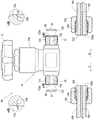
Fig. 9, 11, and 12 are schematic front views in partial cross-section of a connection structure Xa between the piping valve device 1a and the flow path piping 100, fig. 10 is a schematic explanatory view in partial cross-section of the connection structure Xa between the piping valve device 1a and the flow path piping 100, fig. 13 is a perspective view of the removal jig 200a, and fig. 14 and 15 are explanatory views of a state in which the removal jig 200a is removed by the gasket 20 attached to the conduction port 12a of the piping valve device 1 a.
Fig. 9 is a partially sectional schematic front view showing an exploded state of the connection structure Xa, fig. 11 is a partially sectional schematic front view showing the connection structure Xa in a state where the gasket 20 is attached to the conduction port 12a of the pipe valve device 1a, and fig. 12 is a partially sectional schematic front view showing the connection structure Xa in a connected state. Fig. 9, 11, and 12 show a part of the conduction port 12a of the pipe valve device 1a, the gasket 20, and the flow path pipe 100 as vertical sectional views.
Fig. 10 (a) is a partially sectional schematic perspective view showing a state before the gasket 20 is attached to the conduction port 12a of the piping valve device 1a, and fig. 10 (b) is a partially sectional schematic perspective view showing the connection structure Xa in a state where the gasket 20 is attached to the conduction port 12a of the piping valve device 1 a.
Fig. 10 is a perspective view of the introduction port 12a, the gasket 20, and the flow path pipe 100 viewed from the front, the left side, and the plane, but the introduction port 12a, the gasket 20, and the flow path pipe 100, which are annular in shape when viewed from the left side, are partially cut away and shown.
In fig. 13, a portion of the detachment jig 200a on the front side of the column portion 202a is cut away.
Fig. 14 (a) is a partially sectional schematic perspective view showing a state in which the removal jig 200a is disposed in one of the two conduction ports 12a to which the gaskets 20 are attached in the piping valve device 1a, and fig. 14 (b) is a partially sectional schematic perspective view showing a state in which the insertion tip portion 203a of the removal jig 200a is inserted into the opening 21 of the gasket 20 attached to the conduction port 12 a.
Fig. 14 (c) is a partially sectional schematic perspective view showing a state in which the removal jig 200a having the insertion distal end portion 203a inserted into the opening 21 of the washer 20 is tilted, and fig. 14(d) is a partially sectional schematic perspective view showing a state in which the removal jig 200a is further tilted and the washer 20 is removed.
The piping valve device 1a is an on-off valve device that is disposed between the flow path pipes 100 and restricts the conduction of the gas flowing through the conduction space 101 of the flow path pipe 100, unlike the container valve device 1 described above that restricts the conduction of the gas, and is attached to the upper portion of the gas cylinder container.
In the following description, the same reference numerals are used for the same components as those in the connection structure X connecting the container valve device 1 and the flow path pipe 100, and detailed description thereof will be omitted.
Unlike the tank valve device 1 including the main body 10 having the cylinder attachment portion 13 attached to the cylinder tank at the lower portion thereof and the introduction port 12 protruding laterally from the vicinity of the middle portion thereof, the piping valve device 1a is configured to protrude laterally with 2 introduction ports 12a interposed therebetween so as to be positioned on a straight line in a plan view, thereby forming the main body 10a having an inverted T shape in a front view.
A flow path 14 connecting the ends of the two conduction ports 12a is formed inside the body 10a configured as described above. The other structures are the same as those of the container valve device 1, and therefore, detailed description thereof is omitted.
Instead of the tapered space 123 having a truncated conical shape tapering toward the main body side B in the introduction opening 12, the introduction opening 12a of the main body 10a configured as described above is provided with an annular space 123a constituting an annular space one turn smaller than the attachment groove 122. The other structures in the conduction port 12a are the same as those in the conduction port 12, and therefore, the description thereof is omitted.
In the connection structure Xa configured by connecting the pipe valve device 1a configured as described above to the flow path pipe 100, first, the gasket 20 is attached to the attachment groove 122 of the conduction port 12a (see fig. 9 to 11).
In a state where the pipe end 102 is exposed by displacing the nut cap 103, the pipe valve device 1a is disposed between the pipe ends 102 of the flow path pipes 100 disposed at a predetermined interval.
The introduction ports 12a of the pipe valve device 1a disposed between the pipe ends 102 of the flow path pipes 100 disposed at a predetermined interval face the pipe ends 102, respectively, and are in a state of abutting against each other via the gasket 20, and in this state, the cap nuts 103 of the flow path pipes 100 are screwed into the screw portions 121 of the introduction ports 12a, whereby the introduction ports 12a and the flow path pipes 100 can be connected to each other, and the connection structure Xa is configured.
Next, a removal jig 200a for removing the washer 20 attached to the attachment groove 122 in the connection structure Xa configured as described above and a method for removing the washer 20 using the removal jig 200a will be described.
As shown in fig. 13, the removal jig 200a is composed of a cylindrical grip portion 201a gripped by a replacement person and a columnar stay portion 202a projecting upward from the grip portion 201 a.
The pillar portion 202a has a substantially cylindrical shape with a diameter smaller than the root portion at the upper side, the portion with the diameter reduced is an insertion tip portion 203a, and a portion between the pillar portion 202a and the insertion tip portion 203a is an abutment regulating portion 204a with the diameter gradually reduced toward the tip side. The diameter of the insertion tip portion 203a is smaller than the diameter of the opening 21 of the gasket 20.
When the washer 20 attached to the attachment groove 122 is detached using the detachment jig 200a configured as described above, as shown in fig. 14 (a), the detachment jig 200a is disposed in the conduction port 12 so as to extend along the extending direction of the flow path 14, that is, in the direction perpendicular to the washer 20 in the longitudinal section. Then, the insertion tip portion 203a is inserted into the body side B with respect to the opening 21 of the gasket 20. At this time, as shown in fig. 14 (b), the contact restricting portion 204a is inserted until it comes into contact with the edge portion on the distal end side F of the opening 21 of the gasket 20.
In this state, as shown in fig. 15 (a), the removal jig 200a is tilted. Specifically, the distal end side F of the removal jig 200a, which is arranged along the extending direction of the flow path 14 and inserted into the main body side B, is moved downward as indicated by an arrow m, for example, to tilt the removal jig 200 a. Thus, the removal jig 200a is inclined so as to abut against the edge of the body side B of the opening 21 of the washer 20 in a state where the insertion tip portion 203a penetrates the opening 21 of the washer 20 toward the body side B. At this time, as shown in fig. 15 (a), the insertion of the distal end portion of the insertion distal end portion 203a into the annular space 123a can prevent the distal end portion of the insertion distal end portion 203a from interfering with the inner surface of the flow path 14 as the removal jig 200a is tilted.
In this state, by further moving the grip portion 201a in the direction of the arrow m (see fig. 15 (b)), the force input from the grip portion 201a acts on the insertion tip portion 203a toward the tip side F by the principle of leverage with the abutment restricting portion 204a abutting against the corner of the opening edge of the opening 21 as a fulcrum.
Therefore, the insertion tip portion 203a inserted into the annular space 123a applies a force toward the tip side F to the washer 20 positioned on the tip side F of the insertion tip portion 203a, and the washer 20 applied with the force toward the tip side F is pushed out by the insertion tip portion 203a, whereby the washer 20 can be removed from the mounting groove 122.
The connection structure Xa configured as described above can exhibit the same effect as the connection structure X configured by connecting the introduction port 12 and the flow path pipe 100.
The abutment restricting portion 204a is provided at the base end portion of the insertion tip portion 203a of the removal jig 200a and is configured to abut against and restrict the edge portion of the opening 21 when the insertion is at the position of excessive insertion, and by inserting the abutment restricting portion 204a until the abutment restricting portion 204a abuts against the edge portion of the opening 21, the insertion position can be restricted by the abutment restricting portion 204a, and it is possible to prevent the insertion tip portion 203a from being excessively inserted or excessively inserted, and to reliably remove the gasket 20.
Further, since the insertion tip portion 203a is formed to have a diameter larger than the inner diameter of the flow path 14, the insertion tip portion 203a may be formed to have a long length and may be configured to abut against the end portion of the main body side B of the annular space 123a before the abutment restricting portion 204a abuts against the edge portion of the opening 21, thereby preventing the insertion tip portion 203a from being excessively inserted. In this case, even if the contact restricting portion 204a is not provided, the above-described effect can be obtained by inserting the insertion distal end portion 203a until it comes into contact with the end portion of the main body side B, that is, the end portion of the distal end side F of the flow path 14.
In the above description, the connection structure X, Xa connected to the flow passage pipe 100 having the pipe end 102 at the end thereof has been described, but a connection structure Xb may be configured by being connected to a flow passage pipe 100b having the fitting projection 105 at the end of the pipe end 102 as in the us CGA standard, for example, and this will be described with reference to fig. 16.
In the following description, the same reference numerals are used for the same components as those in the connection structure X in which the container valve device 1 and the flow path pipe 100 are connected to each other, and detailed description thereof will be omitted.
As shown in fig. 16, a fitting projection 105 projecting beyond the pipe end 102 is provided at the tip of the flow pipe 100 b. The fitting projection 105 has a diameter smaller than the outer diameter of the flow passage pipe 100 b. Thus, if the flow passage pipe 100b having the fitting convex portion 105 protruding toward the tip end side from the pipe end 102 is connected to the conventional conduction port 12 or the conduction port 12a, the fitting convex portion 105 is connected without interference.
Therefore, the conduction port 12b constituting the connection structure Xb connected to the flow path pipe 100b is provided with the attachment groove 122 similarly to the conduction port 12 or the conduction port 12a, but with respect to the conduction port 12 or the conduction port 12a provided with the tapered space 123 or the annular space 123a between the flow path 14 and the attachment groove 122, the tapered space 123b is provided in the attachment groove 122 in the conduction port 12b, and the fitting projection portion accommodating space 127 accommodating the fitting projection portion 105 is provided between the tapered space 123b and the flow path 14.
That is, the conduction port 12B is arranged in the order of the mounting groove 122, the tapered space 123B, the fitting protrusion accommodating space 127, and the flow path 14 with respect to the conduction port 12 or the conduction port 12a arranged in the order of the mounting groove 122, the tapered space 123 or the annular space 123a, and the flow path 14 from the distal end side F toward the main body side B. In other words, the tapered space 123b is formed between the mounting groove 122 and the fitting projection receiving space 127.
The introduction port 12b configured as described above may be provided in any one of a container valve device such as the container valve device 1 and a pipe valve device such as the pipe valve device 1a, or may be configured by an annular space similar to the annular space 123a instead of the tapered space 123 b.
The washer 20b used for the connection structure Xb has an opening 21b with a larger diameter through which the fitting convex portion 105 can be inserted than the opening 21 of the washer 20 used for the connection structure X and the connection structure Xa. Therefore, the diameter of the distal end side F of the tapered space 123b is also increased from the diameter of the distal end side F of the tapered space 123.
The connection structure Xb formed by connecting the introduction port 12b, the gasket 20b, and the flow path pipe 100b configured as described above can provide the same effects as the connection structure X formed by connecting the container valve device 1 having the introduction port 12 to the flow path pipe 100 and the connection structure Xa formed by connecting the pipe valve device 1a having the introduction port 12a to the flow path pipe 100.
As shown in fig. 8 or 15, the washer 20b mounted in the mounting groove 122 of the conduction port 12b configured as above can be removed by using the removal jig 200 in the same step as the step of removing the washer 20 mounted in the mounting groove 122 of the conduction port 12 or the conduction port 12 a.
In the configuration of the present invention corresponding to the above-described embodiment, the fluid of the present invention corresponds to the gas, and similarly, the flow path corresponds to the flow path 14, the opening and closing valve device corresponds to the container valve device 1, the conduction ports correspond to the conduction ports 12, 12a, 12B, the flow path piping corresponds to the flow path piping 100, 100B, the piping end corresponds to the piping end 102, the connection structure corresponds to the connection structure X, Xa, Xb, the opening corresponds to the opening 21, 21B, the sealing member corresponds to the gasket 20, 20B, the mounting groove corresponds to the mounting groove 122, the back side corresponds to the main body side B, the removal jig corresponds to the removal jig 200, the insertion front end corresponds to the insertion front end 203, 203a, the interference prevention space corresponds to the tapered space 123, 123B or the annular space 123a, the contact surface corresponds to the groove bottom surface 124, the over-insertion prevention means corresponds to the clear groove 204, the abutment restriction portion 204a, the clear indication means corresponds to the clear indication groove 204, and the abutment restricting portion corresponds to the abutment restricting portion 204a or the insertion tip portion 203a formed long, but the present invention is not limited to the configuration of the above-described embodiment, and many embodiments can be obtained.
For example, in the above description, a gas is described as the fluid, but may be a liquid or a gel.
In the above description, the attachment groove 122 is provided in the conduction port 12, but the attachment groove may be provided in the pipe end 102, or the attachment groove may be provided in the pipe end 102 in addition to the attachment groove 122 provided in the conduction port 12. In this way, when the mounting groove is provided in the pipe end 102 in addition to the mounting groove 122 provided in the conduction port 12, the respective groove shapes may be formed in the same shape, and the gasket 20 may be mounted in either one of the groove shapes and the gasket 20 may be fitted in the other mounting groove in the connected state, or the gasket 20 may be mounted in the main mounting groove in either one of the groove shapes and the gasket 20 may be fitted in the other sub-mounting groove in the connected state.
In the above description, the tapered spaces 123, 123B provided on the main body side B of the mounting groove 122 are substantially truncated cone-shaped spaces, and the annular space 123a is formed by an annular space, that is, a space that is continuous in the circumferential direction when viewed from the left side surface. Further, the space may be formed on the main body side B of the opening 21 formed with a small diameter with respect to the flow path 14 with a large diameter.
In the above description, the insertion distal end portions 203 and 203a are formed in a cylindrical shape, but may be a polygonal or elliptical cylindrical body such as a hexagonal cross section, and the diameter may be slightly changed.
Description of the reference symbols
1: a container valve means; 1 a: a piping valve device; 12. 12a, 12 b: a conduction port; 14: a flow path; 20. 20 b: a gasket; 21. 21 b: an opening; 100. 100 b: a flow path pipe; 102: a piping end; 122: mounting grooves; 123. 123 b: a conical space; 123 a: an annular space; 124: the bottom surface of the groove; 200. 200 a: disassembling the jig; 203. 203 a: inserting the front end portion; 204: an explicit slot; 204 a: an abutment restricting section; b: a main body side; x, Xa, Xb: and (5) connecting construction.
Claims (10)
1. A connection structure for connecting a conduction port, which is one end of a flow path, in an on-off valve device having an on-off valve for switching on and off at a middle portion of the flow path through which a fluid is conducted, to a pipe end portion of a flow path pipe through which the fluid is conducted,
the conduction port is disposed in abutment with the pipe end portion,
an annular seal member having an opening through which a substantially columnar insertion tip portion of the removal jig can be inserted is disposed between the conduction port and the pipe end portion,
an installation groove for installing the sealing member is formed in at least one of the conduction opening and the pipe end portion,
an interference prevention space is provided on a back surface side opposite to a side opposite to the other of the conduction port and the pipe fitting end portion in an attached state in which the seal member is attached to the attachment groove, the interference prevention space preventing interference with the insertion tip portion when the removal jig, which inserts the insertion tip portion into the opening in order to remove the seal member, is inclined.
2. The connection configuration according to claim 1,
the mounting groove and the interference preventing space are formed at the conduction port.
3. The connection configuration according to claim 2,
the mounting groove has a contact surface that contacts the seal member with a prescribed pressure receiving area, and,
the interference prevention space is provided on the back surface side and radially inside the mounting groove to which the seal member is mounted.
4. An opening and closing valve device, wherein,
the on-off valve device has an on-off valve for switching on and off at an intermediate portion of a flow path through which a fluid is conducted,
one end of the flow path is used as a conduction port which is in butt joint connection with the end part of the flow path pipe for conducting the fluid,
an installation groove is arranged in the conduction opening, an annular sealing component is installed in the installation groove, the sealing component is provided with an opening through which the approximately columnar insertion front end part in the disassembling jig can be inserted,
an interference prevention space is provided on a back surface side opposite to a side opposite to the pipe end in an attached state in which the seal member is attached to the attachment groove, the interference prevention space preventing interference with the insertion tip portion when the removal jig, the insertion tip portion of which is inserted into the opening, is tilted in order to remove the seal member.
5. The opening-closing valve device according to claim 4,
the mounting groove has a contact surface contacting the seal member with a predetermined pressure receiving area, and
the interference prevention space is provided on the back surface side and radially inside the mounting groove to which the seal member is mounted.
6. A method of removing a seal member, in a connection structure in which a conduit, which is one end of a flow path in which a fluid is conducted, is connected to a pipe end of a flow path pipe in which the fluid is conducted, in an opening/closing valve device having an opening/closing valve for switching opening/closing in a middle portion of the flow path, the seal member being attached to an attachment groove formed in at least one of the conduit and the pipe end,
an interference prevention space is provided on a back surface side opposite to a side opposite to the other of the conduction port and the pipe fitting end portion in an attached state in which the sealing member is attached to the attachment groove, the interference prevention space preventing interference with the insertion tip portion when a removal jig having the insertion tip portion inserted into the opening is tilted to remove the sealing member,
the removal jig, which is inserted with the insertion tip portion inserted through the opening of the sealing member attached to the attachment groove, is inclined with respect to the insertion direction, and the sealing member is removed from the attachment groove.
7. The seal member detaching method according to claim 6,
after the insertion tip portion is inserted into the opening until an excessive insertion prevention unit that prevents the insertion tip portion from being excessively inserted into the opening functions, the removal jig is tilted.
8. The seal member detaching method according to claim 7,
the excessive insertion preventing means is an indicating means which is provided at a proximal end portion of the insertion distal end portion of the removal jig and indicates a position where the excessive insertion is performed,
the transparent unit is inserted until the transparent unit is positioned at the edge of the opening.
9. The seal member detaching method according to claim 7,
the excessive insertion preventing means is an abutment restricting portion which is provided at a proximal end portion of the insertion distal end portion of the removal jig and which abuts against an edge portion of the opening to restrict the excessive insertion when the removal jig is inserted to a position where the excessive insertion is performed,
the abutment restricting portion is inserted until it abuts against an edge of the opening.
10. The seal member detaching method according to claim 7,
the insertion tip portion insertable into the opening is formed in a non-insertion shape that is not insertable into one end of the flow path,
the insertion tip portion formed by the non-insertion shape functions as the over-insertion preventing means.
Applications Claiming Priority (3)
| Application Number | Priority Date | Filing Date | Title |
|---|---|---|---|
| JP2019-236115 | 2019-12-26 | ||
| JP2019236115A JP7408079B2 (en) | 2019-12-26 | 2019-12-26 | How to remove the connection structure connecting the conduction port and the end of the pipe, the on-off valve device, and the sealing member |
| PCT/JP2020/046804 WO2021131917A1 (en) | 2019-12-26 | 2020-12-15 | Connection structure for connecting conduction port and pipe end, open/close valve device, and removal method for sealing member |
Publications (1)
| Publication Number | Publication Date |
|---|---|
| CN114829812A true CN114829812A (en) | 2022-07-29 |
Family
ID=76574560
Family Applications (1)
| Application Number | Title | Priority Date | Filing Date |
|---|---|---|---|
| CN202080087975.6A Pending CN114829812A (en) | 2019-12-26 | 2020-12-15 | Connection structure for connecting conduction port and pipe end, opening/closing valve device, and method for removing seal member |
Country Status (5)
| Country | Link |
|---|---|
| JP (1) | JP7408079B2 (en) |
| KR (1) | KR20220113802A (en) |
| CN (1) | CN114829812A (en) |
| TW (1) | TWI750938B (en) |
| WO (1) | WO2021131917A1 (en) |
Families Citing this family (2)
| Publication number | Priority date | Publication date | Assignee | Title |
|---|---|---|---|---|
| KR102485744B1 (en) * | 2022-07-22 | 2023-01-09 | 김팔남 | Connector for a tube sealing device |
| TWI820988B (en) * | 2022-10-28 | 2023-11-01 | 萬潤科技股份有限公司 | Installation device and method of sealing ring of liquid valve mechanism |
Family Cites Families (7)
| Publication number | Priority date | Publication date | Assignee | Title |
|---|---|---|---|---|
| JP2003074798A (en) | 2001-08-30 | 2003-03-12 | Koda:Kk | High pressure gas cylinder valve |
| JP3780277B2 (en) | 2003-11-06 | 2006-05-31 | シーケーディ株式会社 | Seal structure for connection part of fluid equipment |
| JP4679188B2 (en) * | 2005-03-15 | 2011-04-27 | 英夫 吉田 | Gas cylinder breaker |
| JP4746487B2 (en) | 2006-06-22 | 2011-08-10 | シーケーディ株式会社 | Removal tool |
| US7905247B2 (en) * | 2008-06-20 | 2011-03-15 | Praxair Technology, Inc. | Vacuum actuated valve for high capacity storage and delivery systems |
| JP7100999B2 (en) | 2018-03-08 | 2022-07-14 | 三菱重工業株式会社 | Plug plug, plug plug attachment / detachment jig, plug plug mounting method, plug plug removal method, and plug plug maintenance method |
| TWM564116U (en) * | 2018-04-18 | 2018-07-21 | 莊加嵩 | Super flow temperature-controlling fuel gas switch |
-
2019
- 2019-12-26 JP JP2019236115A patent/JP7408079B2/en active Active
-
2020
- 2020-12-07 TW TW109143048A patent/TWI750938B/en active
- 2020-12-15 CN CN202080087975.6A patent/CN114829812A/en active Pending
- 2020-12-15 WO PCT/JP2020/046804 patent/WO2021131917A1/en active Application Filing
- 2020-12-15 KR KR1020227024636A patent/KR20220113802A/en not_active Application Discontinuation
Also Published As
| Publication number | Publication date |
|---|---|
| KR20220113802A (en) | 2022-08-16 |
| JP2021105410A (en) | 2021-07-26 |
| WO2021131917A1 (en) | 2021-07-01 |
| TWI750938B (en) | 2021-12-21 |
| TW202129192A (en) | 2021-08-01 |
| JP7408079B2 (en) | 2024-01-05 |
Similar Documents
| Publication | Publication Date | Title |
|---|---|---|
| CN114829812A (en) | Connection structure for connecting conduction port and pipe end, opening/closing valve device, and method for removing seal member | |
| US7484770B2 (en) | Connecting structure for piping members | |
| EP1982101B1 (en) | Sealed flange joint for high pressure and high purity gas channels | |
| US20040144734A1 (en) | Fluid filter, drain mechanism thereof, draining jig used in fluid filter and draining method of fluid filter | |
| JP6517040B2 (en) | High pressure filter device and hydrogen station using the same | |
| KR20130086908A (en) | A pipe connector | |
| CN110173584B (en) | Valve device | |
| KR20210015764A (en) | Pinch valve | |
| CN112424512B (en) | Connection structure of conduction port and piping end, opening and closing valve device, and removal jig | |
| US4537214A (en) | Single seal pipeline tapping fixture having secure valve | |
| KR20050041961A (en) | Connector for dispensing liquid from a tank | |
| EP3150886B1 (en) | Structure and method for fixing ball seat for ball valve, trunnion-type ball valve, and hydrogen station using said valve | |
| JP2016537576A (en) | valve seat | |
| KR101622129B1 (en) | Fuel filling valve assembly | |
| JP4660186B2 (en) | Joint holding member and instrument comprising joint holding member and joint member | |
| JP6682700B2 (en) | Sealing device and sealing method | |
| KR101205478B1 (en) | fuel tank structure for preventing a leakage on the top cover thereof | |
| KR101840798B1 (en) | Cover apparatus of pipe connection portion | |
| KR100647013B1 (en) | Device for enlarging the sealing efficiency of safety valve | |
| JP6738288B2 (en) | Connection member attaching/detaching method and attaching/detaching device | |
| KR20220010889A (en) | Lpg valve | |
| JP2952174B2 (en) | Valve seats such as breather valves | |
| EP0987196A2 (en) | Dual containment isolation valve and corresponding gas/liquid container | |
| KR200341420Y1 (en) | check valve | |
| CN109563955A (en) | Hydraulic connectors and matching piece for quick connector |
Legal Events
| Date | Code | Title | Description |
|---|---|---|---|
| PB01 | Publication | ||
| PB01 | Publication | ||
| SE01 | Entry into force of request for substantive examination | ||
| SE01 | Entry into force of request for substantive examination |