Ratchet spanner
Technical field
The present invention relates to when the assembling of automobile and industrial machine etc. or dismounting, to be used for spiral or nut are tightened or loosened the improvement of the ratchet spanner of operation.
Background technology
In the past, bolt or nut etc. reliably and was was promptly tightened or loosened one to adopting electronic or manual ratchet spanner.Existing ratchet spanner now illustrates the structure of its major part according to Figure 12 to Figure 19 shown in No. the 55378999th, United States Patent (USP).
The movement converter 14 of the prior art that as shown in figure 12, in housing 10, have motor 12, the rotating speed of this motor 12 is changed, be rotated motion and the bent axle 16 of the motion that reciprocatingly slides by this movement converter 14.
As shown in figure 13, the core 18 in that the front end of above-mentioned bent axle 16 is formed with and its center is eccentric and parallel with its center is equipped with the axle bush 22 with inserting hole 20 sliding freely on this core 18.Shown in Figure 12 and 14, be formed with a pair of tubular maintaining part 24 at the front end of housing 10, between this a pair of tubular maintaining part 24, have rock body 26 as shown in figure 13.Central authorities at this rock body 26 form hole 28, and the inwall in this hole 28 is formed with internal gear 30.The front end of rock body 26 has a pair of wrist 32, and forms spatial portion 34 between this a pair of wrist 32.Above-mentioned axle bush 22 is rotated freely and disengageably is not entrenched in this spatial portion 34.
As shown in figure 15, be used to make handle 36 that bolt etc. intermittently rotates by columned base portion 38, constitute with the holding section 40 of the integrally formed cubic of this base portion 38.The circumferential location of the base portion 38 of this handle 36 is inserted in the hole 28 of above-mentioned rock body 26.The rock body 26 that handle 36 is installed is remained between a pair of tubular maintaining part 24 of the housing 10 shown in Figure 12 and 14.Along with the rotation of bent axle 16, rock body 26 is that the center is shaken with the state that remains in the housing 10 with the central shaft in its hole 28.
It is that two wing members 44 are freely shaken at the center that handle 36 has in the inside of columned base portion 38 with pin 42.Be formed with a plurality of pawls 46 respectively at the two ends, the left and right sides of each wing member 44.Form at the axle center of columned base portion 38 porose 48, and in the inside in this hole 48 the chimeric columned switch piece 52 (Figure 16) that integrally formed switch knob 50 is arranged.Switch piece 52 is installed into and can rotates in the certain angle scope with respect to handle 36.
As Figure 16 and shown in Figure 17, in switch piece 52, form 2 holes altogether, and form the peristome in these holes 54 in the opposite side positions that are in 180 degree with respect to axial vertical direction and on direction of principal axis differing heights position.The push rod 56 that has the tubular of an end locking in the inside in each hole 54, and be used in the tubular inside of each push rod 56 with each push rod 56 from the hole 54 inside to the spring 58 of the outside roof pressure direction application of force.Shown in Fig. 17, the locking position of push rod 56 is 54 outstanding to the outside at the elastic force of spring 58 and from the hole, and the locking position of push rod 56 contacts also roof pressure wing member 44 shapes with wing member 44.
With the chimeric state in the hole 48 of the base portion 38 of handle 36 under by the switch knob 50 that rotates switch piece 52 switch piece 52 is for example done about 90 degree rotations along both forward and reverse directions, and in the positions of the positive and negative rotation of about 90 degree switch piece 52 is remained on stable state (state of Figure 18 and Figure 19) respectively.At the state of Figure 18 and Figure 19, each wing member 44 roof pressure is become internal gear 30 engagements of pawl 46 and above-mentioned rock body 26 of the left and right sides either side of each wing member 44 by push rod 56 and spring 58.Under the state of Figure 18, push rod 56 is a side of the center roof pressure wing member 44 of shaking with pin 42.Switch to the state of Figure 19 by rotating switch knob 50 from the state of Figure 18, the position of push rod 56 roof pressure wing members 44 moves by side to opposite side from one of wing member 44.By switching, move by side to opposite side with the pawl 46 of each wing member 44 of internal gear 30 engagement of rock body 26 from one, and carry out the rotation and the switching of unclamping the rotation of direction of fastening direction by this switch knob 50.
In a single day each wing member 44 is set at and makes rock body 26 along a direction (direction that keeps engagement) rotation under the state of internal gear 30 engagements of the pawl 46 of each wing member 44 and rock body 26, then the pawl 46 of each wing member 44 moved with rock body 26 again with internal gear 30 engagements, the while of rock body 26.On the other hand, in case rock body 26 is rotated in opposite direction, then the pawl 46 of each wing member 44 contacts with the internal gear 30 of rock body 26 and skids and no longer engagement, and each wing member 44 does not move with rock body 26.
That is, under the state of Figure 18, rock body 26 is rotated along the A direction be fastening operation, rock body 26 is rotated then for being used to lay in the feed motion that carries out fastening power next time along the B direction.Fastening so repeatedly operation and feed motion and carry out fastening.In addition, in case switch to the state of Figure 19 from the state of Figure 18, rock body 26 is rotated along the C direction becomes unclamp operation, becomes feed motion and rock body 26 is rotated along the D direction.
As Figure 12 and shown in Figure 14, the holding section 40 of handle 36 is generally cube shaped, and its holding section 40 is outstanding with respect to the length direction of housing 14 direction that meets at right angles by front end one side's of housing 10 tubular support sector 24.Loading and unloading are equipped with freely and are used for transmitting the socket 60 that intermittently rotatablely moves between ratchet spanner and bolts etc. on the holding section 40 of this handle 36.This socket 60 is cylindric, is provided with first hole 62 that is used for the chimeric quadrangular section in the holding section 40 of above-mentioned handle 36 in the end of one side, is provided with second hole 64 that is used for the chimeric hexagonal cross-section of not shown bolt in its opposing party's end.Using under the situation of ratchet spanner, is socket 60 is contained in the holding section 40 of handle 36 and is used to carry out between the bolt of fastening operation or unclamp operation.
The below action of the ratchet spanner of the above structure of explanation.
At first, in case motor 12 shown in Figure 12 rotates, promptly bent axle 16 is rotated by existing movement converter 14.In case this bent axle 16 rotates, the core 18 of this bent axle 16 is that the center makes axle bush 22 make the planet circular motion with the axle center of bent axle 16 promptly.Because the motion of axle bush 22, making rock body 26 is that the center is shaken with the central shaft of the columned base portion 38 of handle 36.
At this rock body 26 when a direction is shaken, be installed in the wing member 44 on the handle 36 outstanding side pawl 46 and rock body 26 internal gear 30 engagements and make handle 36 rotations and with fastening (the A directions of Figure 18) such as bolts.Thereafter, when this rock body 26 shakes round about, the pawl 46 of outstanding side not with internal gear 30 engagements of rock body 26,26 of rock bodies shake and handle 36 does not rotate (the B direction of Figure 18).Thereafter, rock body 26 is once more when last direction is shaken, and is once more that bolt etc. is fastening.That is, in this ratchet spanner, only off and on that bolt etc. is fastening when a direction is shaken at rock body 26.
In the ratchet spanner that adopts 2 wing members 44, when shaking of rock body 26 is slow, the pawl 46 of wing member 44 moves along the internal gear 30 of rock body 26, but when in a single day shaking at a high speed for the raising operating efficiency, wing member 44 is center vibration and producing on wing member 44 by shaking the so-called covibration that speed fluctuation causes with pin 42 promptly, as shown in figure 20, be that pawl 46 with the wing member 44 of internal gear 30 engagement of rock body 26 with internal gear 30 the bigger disengagement (excess of stroke: phenomenon overshooting) takes place temporarily.In case this excess of stroke phenomenon takes place, it is slower then to get back to wing member 44 engagements, and the pawl 46 of 44 liang of sides of wing member does not carry out fastening with internal gear 30 engagements.
In case excess of stroke phenomenon takes place, promptly has this situation: become as shown in figure 21 " eight " font engagement with internal gear 30 engagements with the pawl 46 of engaged claw 46 opposite sides.Rock body 36 carries out same shaking at state and rock body 26 as shown in figure 21, thereby produces the inappropriate situation that can not carry out fastening rotation fully.
Carrying out the occasion of rotation at a high speed, wing member 44 produces vibration and has the point (this point is called resonance point) that makes this vibration amplification with spring 58.Though this resonance point is difference with the intensity of the quality of wing member 44 and spring 58, its resonance point must exist when rotating at a high speed.Thereby produce as Figure 20 or inappropriate situation as shown in Figure 21.
In ratchet spanner, switch piece 52 is to be rotatably installed on the handle 36, and switch piece 52 rotates with handle 36.In case handle 36 carries out fastening rotation and stops operating immediately after fastening, 1 switch piece 52 that is contained on the handle 36 further rotates because of inertia force.At this moment, the reaction force of spring 58 diminishes, at switch piece 52 not by the occasion of spring 58 roof pressures, switch piece 52 counter-rotating, and have the so-called inappropriate situation that fastening operation and unclamp operation are switched.Switch for this counter-rotating unwillingly that prevents this switch piece 52, preferably strengthen the spring force of spring 58.
In the ratchet spanner of prior art, for will suppressing excess of stroke phenomenon, no matter whether the spring force of spring 58 is powerful, is arranged to not make wing member 44 to be positioned at out of position limiter and gets final product.For preventing counter-rotating switching unwillingly, some get final product the spring force of spring 58 greatly.But,, but can't be strengthened to the spring force of spring 58 more than the present situation for the little spring 58 of present situation.In addition, though also limiter can be arranged to not make wing member 44 to move on the unsuitable position, can't guarantee to be provided with the space of its limiter.
The present invention in view of this, its purpose is to provide a kind of can prevent the excess of stroke, can prevent the ratchet spanner that unwillingly reverses and switch simultaneously again.
Content of the present invention
For achieving the above object, ratchet spanner of the present invention comprises: housing, have and shake the rock body that is installed in the internal gear in this housing freely, include the handle that has the wing member of the pawl that meshes with its internal gear in the left and right sides, can be to the switch piece of scope rotation at a certain angle in this handle, be formed at the hole in this switch piece, be positioned at the push rod in this hole, the pawl that is positioned at this hole and is used for making above-mentioned wing member through above-mentioned push rod is along the spring that contacts the above-mentioned wing member of direction roof pressure with above-mentioned internal gear, be characterized in having in the inside in above-mentioned hole and be used to resist the elastic component that above-mentioned push rod moves to above-mentioned hole private side.
As mentioned above, ratchet spanner of the present invention ties up to and has the ratchet spanner that push rod is carried out being provided with in the hole of the spring that roof pressure uses the elastic components such as rubber that are used to resist the locomotivity in push-rod hole.Consequently, even the masterpiece of excess of stroke direction is used on the wing member, or the vibration of wing member and spring is the amplification frequency when rotating at a high speed, total reaction force by elastic component and spring and as the effect of the limiter of the little elastic component of compression ratio, can stop the pawl of the wing member that is meshing to break away from internal gear significantly, thereby prevent the excess of stroke.
In addition, in the present invention owing to can increase confining force, so can prevent the counter-rotating switching unwillingly of switch piece by spring and elastic component to the handle of switch piece.
The accompanying drawing simple declaration
Fig. 1 is the major part profile of ratchet spanner of the present invention.
Fig. 2 is the amplification profile of major part.
Fig. 3 is the profile of another example of expression ratchet spanner of the present invention.
Fig. 4 is the profile of another example of expression ratchet spanner of the present invention.
Fig. 5 is the profile of another example of expression ratchet spanner of the present invention.
Fig. 6 is the profile of another example of expression ratchet spanner of the present invention.
Fig. 7 is the profile of another example of expression ratchet spanner of the present invention.
Fig. 8 is the profile of another example of expression ratchet spanner of the present invention.
Fig. 9 is the profile of another example of expression ratchet spanner of the present invention.
Figure 10 is the profile of another example of expression ratchet spanner of the present invention.
Figure 11 is the profile of another example of expression ratchet spanner of the present invention.
Figure 12 is the front view of ratchet spanner in the past.
The exploded perspective view of the bent axle that Figure 13 uses among Figure 12 for expression and the annexation of rock body.
Figure 14 is illustrated in the stereogram that the state of axle bush is installed in the ratchet spanner of Figure 12.
The stereogram of the handle that Figure 15 uses among Figure 12 for expression.
Figure 16 is the major part profile of the ratchet spanner of Figure 12.
Figure 17 is the amplification profile of the major part of Figure 16.
Figure 18 is the profile of a side's of rock body and wing member good engagement state in the ratchet spanner of expression Figure 12.
Figure 19 is the profile of the opposing party's of rock body and wing member good engagement state in the ratchet spanner of expression Figure 12.
Figure 20 is the profile of the engagement disengaged condition of rock body and wing member in the ratchet spanner of expression Figure 12.
Figure 21 is the profile of the inappropriate engagement of rock body and wing member in the ratchet spanner of expression Figure 12.
The specific embodiment
First example of the present invention below is described with reference to the accompanying drawings.
Fig. 1 is the major part profile of ratchet spanner of the present invention, and Fig. 2 is the amplification profile of Fig. 1 major part.All and the same label of Figure 12 to Figure 19 are all represented same member in Fig. 1 and Fig. 2.In the present invention, with respect to axially forming 2 holes 54 altogether for vertical direction and on axial differing heights position, the peristome in these holes 54 is formed at mutually spends the position of opposite sides towards 180 in switch piece 52.The inside in each hole 54 is an end locking, and have push rod 56 and be used in the tubular inside of each push rod 56 with push rod 56 from the hole 54 inside to the spring 58 of the outside roof pressure direction application of force.As depicted in figs. 1 and 2, it is 54 outstanding to the outside that the locking position of push rod 56 is set at by spring 58 application of forces from the hole, and its outer surface contacts also roof pressure wing member 44 with wing member 44.Said structure is same as the prior art.
In the present invention, 54 inside has and is used to resist to rubber-like elastic components such as inner that move, the rubber in the hole 54 of push rod 56 in the hole.In Fig. 1 and Fig. 2, the elastic component 66 of solid rod-like is housed in the axial inner space of spring 58.
In common state, an end of elastic component 66 is contacted with the locked end of the tubular push rod 56 of an end locking, and the other end is contacted with switch piece 52.Under the state in the axial inner space of spring 58 that elastic component 66 is packed into, on elastic component 66, apply compression stress or do not apply compression stress all right.In addition, though be that an end of elastic component 66 is contacted with the locked end of push rod 56 as previously mentioned, and the other end is contacted with switch piece 52, arbitrary end of push rod 56 is not contacted.
Owing to adopt said structure, in case to the power of wing member 44 effect excess of stroke directions, then by 44 pairs of push rods of wing member 56 roof pressure and make elastic component 66 and spring 58 compressions in addition.Owing in elastic component 66 and spring 58, produce reaction force, stop the pawl 46 of wing member 44 to break away from internal gear 30 significantly by this reaction force, thereby can prevent the excess of stroke for compression.
In addition, it is little than spring 58 to be set at compression ratio as the material with elastic component 66, and then elastic component 66 plays a part the limiter of wing member 44 and the pawl 46 of prevention wing member 44 are broken away from internal gear 30 significantly, thereby can prevent the excess of stroke.
Also have, though the frequency of the vibration amplification of wing member 44 and spring 58 can appear making when rotating at a high speed, because this moment, elastic component 66 played a part limiter or shock absorber to wing member 44, so even when high speed is rotated, also can prevent the excess of stroke.
And when rotating at a high speed, elastic component 66 is made rapid movement with respect to wing member 46, even the elastic component of being made by the rubber-like material 66 also can produce bigger counter-force to wing member 46 according to its roof pressure speed.Therefore, elastic component 66 plays a part limiter or shock absorber when rotating owing to high speed, so even also can prevent the excess of stroke when rotating at a high speed.
In addition, in case roof pressure push rod 56 then because compressed elastic component 66 contacts with spring 58, and elastic component 66 can absorb the vibration of push rod 56 and spring 58 and suppress covibration, can also prevent the excess of stroke by suppressing covibration.
And switch piece 52 increases by made the confining force for the switch piece 52 of handle 36 by the elastic component of making as the rubber of elastomeric material etc. 66, so can prevent switch piece 52 counter-rotatings switching unwillingly takes place.
In addition, in example of the present invention,, can be applicable to that also wing member 44 is 1 a situation though be to be illustrated for the situation that on handle 36, has 2 wing members 44.
Following second example that ratchet spanner of the present invention is described according to Fig. 3.
This example and Fig. 1 and Fig. 2 are same, along having elastic component in the space of the central shaft of spring 58.In push rod 68, with the opposite face 70 on spring 58 opposites on form to the outstanding protrudent pin 72 in the inside in hole 54.In the inner space of spring 58, have the elastic component 74 of tubular, and make protrudent pin 72 be entrenched in the inboard of the elastic component 74 of this tubular.In this push rod 68, the size of opposite face 70 becomes and can contact with an end of spring 58 and an end of elastic component 74.
In this structure, in case the masterpiece of excess of stroke direction is used on the wing member 44, promptly make the elastic component 74 of tubular with spring 58 compressions by push rod 68, reaction force by these elastic components 74 and spring 58 stops the pawl 46 of wing member 44 to break away from internal gear 30 significantly, thereby can prevent the excess of stroke.
Following the 3rd example that ratchet spanner of the present invention is described according to Fig. 4.In this example, the outside that ties up to spring 58 has the ratchet spanner of the elastic component of tubular.
It in this example the push rod 56 that adopts the tubular of an end locking illustrated in figures 1 and 2.One end of the elastic component 76 of one end of spring 58 and tubular is housed in the inner space of the tubular of this push rod 56.The elastic component 76 of tubular is configured in the outside of spring 58.
In this structure, in case the masterpiece of excess of stroke direction is used on the wing member 44, promptly make the elastic component 76 of tubular with spring 58 compressions by push rod 56, reaction force by these elastic components 76 and spring 58 stops the pawl 46 of wing member 44 to break away from internal gear 30 significantly, thereby can prevent the excess of stroke.
Following the 4th example that ratchet spanner of the present invention is described according to Fig. 5.In this example, the outside that ties up to spring 58 has the ratchet spanner of the elastic component of tubular.
It in this example the push rod 56 that adopts the tubular of an end locking illustrated in figures 1 and 2.One end of spring 58 is housed in the inner space of the tubular of this push rod 56.In hole 54 along the elastic component 78 that has tubular on the extended line of the cylindrical portion 77 of push rod 56, in the outside of spring 58.The internal diameter of the elastic component 78 of this tubular and external diameter preferably and the internal diameter and the external diameter of the cylindrical portion of push rod 56 roughly the same, be limited to this but have more than.
In this structure, in case the masterpiece of excess of stroke direction is used on the wing member 44, promptly make the elastic component 78 of tubular with spring 58 compressions by push rod 56, reaction force by these elastic components 78 and spring 58 stops the pawl 46 of wing member 44 to break away from internal gear 30 significantly, thereby can prevent the excess of stroke.
In addition, though the state that to be expression normal conditions lower push-rod 56 in Fig. 5 separate with the elastic component 78 of tubular also can be a state of contact generally.
The variation of Fig. 5 shown in Fig. 6.Though Fig. 6 is for making elastic component 80 contact conditions of push rod 56 and tubular, but in the contact-making surface of push rod 56 and the elastic component 80 of tubular, the free front end that ties up to the cylindrical portion 77 of push rod 56 forms stage portion 82, forms the stage portion that the stage portion 82 with push rod 56 cooperatively interacts in elastic component 80 sides.Though the stage portion 82 of push rod 56 is expressed as the inboard shape longer than the outside, stage portion also can be the outside than inboard long shape.
Fig. 7 also is the variation of Fig. 5.The same with Fig. 6 in Fig. 7, form stage portion 82 at free front end in the cylindrical portion 77 of push rod 56.The elastic component 84 of tubular is set for the outside of extending outstanding inboard protuberance 85 from the position of the stage portion 82 of push rod 56 vertically chimeric.The thickness of this elastic component 84 is about half of thickness of elastic component 80 among elastic component 78 among Fig. 5 or Fig. 6.
Obviously in Fig. 7, extend outstanding protuberance 85 from the position of stage portion 82 vertically and be expressed as the inboard shape longer, but the protuberance 85 of push rod 56 also can be the outside than inboard long shape than the outside.In this case, the elastic component 84 of tubular is set inboard chimeric with the protuberance 85 of push rod 56 for.
Following the 5th example that ratchet spanner of the present invention is described according to Fig. 8.In this example, the outside that ties up to spring 58 has the ratchet spanner of the elastic component of tubular.Adopt push rod 68 in this example with protrudent pin shown in Figure 3 72.And make the outside of the inner space of spring 58 1 ends and protrudent pin 72 chimeric.The elastic component 86 that has tubular in the outside of this spring 58.And an end of spring 58 and an end of elastic component 86 are contacted with the opposite face 70 of push rod 56.
In this structure, in case the masterpiece of excess of stroke direction is used on the wing member 44, even the elastic component of tubular 86 is with spring 58 compression, the reaction force by these elastic components 86 and spring 58 stops the pawl 46 of wing member 44 to break away from internal gear 30 significantly, thereby can prevent the excess of stroke.
Following the 6th example that ratchet spanner of the present invention is described according to Fig. 9.Fig. 9 represents spring 58 is placed in the solid elastomeric part 88 of internal state.Promptly by the elastic component 88 of spring 56 is housed in the molded formation.In this case, push rod can be the push rod 56 of the tubular of Fig. 1 or an end locking shown in Figure 4, also can be Fig. 3 or the push rod with opposite face 70 68 shown in Figure 6.
In this structure, can stop the pawl 46 of wing member 44 to break away from internal gear 30 significantly by the reaction force of spring 58 and elastic component 86, thereby prevent the excess of stroke.
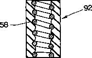
The hollow elasticity spare 90 that also can adopt as shown in Figure 10 internal mode to be shaped on spring 58 replaces the structure of Fig. 9.In addition, also can adopt as shown in figure 11, be molded with the such structure of tubular elastic component 92 in the outside of spring 58.