CN114803619B - Textile fabric cloth inspecting machine - Google Patents
Textile fabric cloth inspecting machine Download PDFInfo
- Publication number
- CN114803619B CN114803619B CN202210732500.9A CN202210732500A CN114803619B CN 114803619 B CN114803619 B CN 114803619B CN 202210732500 A CN202210732500 A CN 202210732500A CN 114803619 B CN114803619 B CN 114803619B
- Authority
- CN
- China
- Prior art keywords
- rollers
- rack
- roller
- fabric
- marking
- Prior art date
- Legal status (The legal status is an assumption and is not a legal conclusion. Google has not performed a legal analysis and makes no representation as to the accuracy of the status listed.)
- Active
Links
- 239000004744 fabric Substances 0.000 title claims abstract description 312
- 239000004753 textile Substances 0.000 title claims abstract description 28
- 239000000463 material Substances 0.000 claims abstract description 214
- 230000007246 mechanism Effects 0.000 claims abstract description 151
- 239000000428 dust Substances 0.000 claims abstract description 115
- 238000004140 cleaning Methods 0.000 claims abstract description 70
- 238000007599 discharging Methods 0.000 claims abstract description 70
- 238000010409 ironing Methods 0.000 claims abstract description 67
- 238000003825 pressing Methods 0.000 claims abstract description 66
- 238000001035 drying Methods 0.000 claims abstract description 49
- 238000004506 ultrasonic cleaning Methods 0.000 claims abstract description 49
- 238000007689 inspection Methods 0.000 claims abstract description 28
- 238000010438 heat treatment Methods 0.000 claims abstract description 13
- 238000004891 communication Methods 0.000 claims abstract description 12
- 239000011449 brick Substances 0.000 claims abstract description 10
- 238000005485 electric heating Methods 0.000 claims abstract description 10
- 230000007547 defect Effects 0.000 claims description 45
- 239000002994 raw material Substances 0.000 claims description 40
- 239000007788 liquid Substances 0.000 claims description 28
- 238000003860 storage Methods 0.000 claims description 27
- 230000000670 limiting effect Effects 0.000 claims description 15
- 238000010521 absorption reaction Methods 0.000 claims description 12
- 210000004209 hair Anatomy 0.000 claims description 8
- 238000001125 extrusion Methods 0.000 claims description 6
- 238000009958 sewing Methods 0.000 claims description 6
- 238000005498 polishing Methods 0.000 claims 1
- 230000000694 effects Effects 0.000 description 18
- 238000005096 rolling process Methods 0.000 description 8
- 239000012535 impurity Substances 0.000 description 7
- 238000000034 method Methods 0.000 description 7
- 238000005406 washing Methods 0.000 description 7
- 230000009471 action Effects 0.000 description 5
- 230000008569 process Effects 0.000 description 5
- 238000001514 detection method Methods 0.000 description 4
- 230000000630 rising effect Effects 0.000 description 4
- 239000002699 waste material Substances 0.000 description 4
- 238000012545 processing Methods 0.000 description 3
- 238000012360 testing method Methods 0.000 description 3
- 230000037303 wrinkles Effects 0.000 description 3
- XEEYBQQBJWHFJM-UHFFFAOYSA-N Iron Chemical compound [Fe] XEEYBQQBJWHFJM-UHFFFAOYSA-N 0.000 description 2
- 230000015572 biosynthetic process Effects 0.000 description 2
- 238000009960 carding Methods 0.000 description 2
- 210000001520 comb Anatomy 0.000 description 2
- 238000005516 engineering process Methods 0.000 description 2
- 238000007667 floating Methods 0.000 description 2
- 230000003760 hair shine Effects 0.000 description 2
- 239000003550 marker Substances 0.000 description 2
- 238000012986 modification Methods 0.000 description 2
- 230000004048 modification Effects 0.000 description 2
- 238000005507 spraying Methods 0.000 description 2
- 230000001360 synchronised effect Effects 0.000 description 2
- 238000009941 weaving Methods 0.000 description 2
- 238000004804 winding Methods 0.000 description 2
- 240000007594 Oryza sativa Species 0.000 description 1
- 235000007164 Oryza sativa Nutrition 0.000 description 1
- 230000009286 beneficial effect Effects 0.000 description 1
- 238000007664 blowing Methods 0.000 description 1
- 230000008859 change Effects 0.000 description 1
- 230000010405 clearance mechanism Effects 0.000 description 1
- 239000003086 colorant Substances 0.000 description 1
- 238000010276 construction Methods 0.000 description 1
- 238000006073 displacement reaction Methods 0.000 description 1
- 239000000284 extract Substances 0.000 description 1
- 230000006698 induction Effects 0.000 description 1
- 229910052742 iron Inorganic materials 0.000 description 1
- 238000007639 printing Methods 0.000 description 1
- 230000008439 repair process Effects 0.000 description 1
- 235000009566 rice Nutrition 0.000 description 1
- 238000007619 statistical method Methods 0.000 description 1
- 210000002268 wool Anatomy 0.000 description 1
Images


Classifications
-
- B—PERFORMING OPERATIONS; TRANSPORTING
- B65—CONVEYING; PACKING; STORING; HANDLING THIN OR FILAMENTARY MATERIAL
- B65H—HANDLING THIN OR FILAMENTARY MATERIAL, e.g. SHEETS, WEBS, CABLES
- B65H19/00—Changing the web roll
- B65H19/10—Changing the web roll in unwinding mechanisms or in connection with unwinding operations
- B65H19/12—Lifting, transporting, or inserting the web roll; Removing empty core
- B65H19/126—Lifting, transporting, or inserting the web roll; Removing empty core with both-ends supporting arrangements
-
- B—PERFORMING OPERATIONS; TRANSPORTING
- B65—CONVEYING; PACKING; STORING; HANDLING THIN OR FILAMENTARY MATERIAL
- B65H—HANDLING THIN OR FILAMENTARY MATERIAL, e.g. SHEETS, WEBS, CABLES
- B65H19/00—Changing the web roll
- B65H19/22—Changing the web roll in winding mechanisms or in connection with winding operations
- B65H19/30—Lifting, transporting, or removing the web roll; Inserting core
-
- D—TEXTILES; PAPER
- D06—TREATMENT OF TEXTILES OR THE LIKE; LAUNDERING; FLEXIBLE MATERIALS NOT OTHERWISE PROVIDED FOR
- D06B—TREATING TEXTILE MATERIALS USING LIQUIDS, GASES OR VAPOURS
- D06B13/00—Treatment of textile materials with liquids, gases or vapours with aid of vibration
-
- D—TEXTILES; PAPER
- D06—TREATMENT OF TEXTILES OR THE LIKE; LAUNDERING; FLEXIBLE MATERIALS NOT OTHERWISE PROVIDED FOR
- D06B—TREATING TEXTILE MATERIALS USING LIQUIDS, GASES OR VAPOURS
- D06B23/00—Component parts, details, or accessories of apparatus or machines, specially adapted for the treating of textile materials, not restricted to a particular kind of apparatus, provided for in groups D06B1/00 - D06B21/00
- D06B23/20—Arrangements of apparatus for treating processing-liquids, -gases or -vapours, e.g. purification, filtration or distillation
-
- D—TEXTILES; PAPER
- D06—TREATMENT OF TEXTILES OR THE LIKE; LAUNDERING; FLEXIBLE MATERIALS NOT OTHERWISE PROVIDED FOR
- D06C—FINISHING, DRESSING, TENTERING OR STRETCHING TEXTILE FABRICS
- D06C15/00—Calendering, pressing, ironing, glossing or glazing textile fabrics
- D06C15/10—Calendering, pressing, ironing, glossing or glazing textile fabrics between flat plates of a press
-
- D—TEXTILES; PAPER
- D06—TREATMENT OF TEXTILES OR THE LIKE; LAUNDERING; FLEXIBLE MATERIALS NOT OTHERWISE PROVIDED FOR
- D06G—MECHANICAL OR PRESSURE CLEANING OF CARPETS, RUGS, SACKS, HIDES, OR OTHER SKIN OR TEXTILE ARTICLES OR FABRICS; TURNING INSIDE-OUT FLEXIBLE TUBULAR OR OTHER HOLLOW ARTICLES
- D06G1/00—Beating, brushing, or otherwise mechanically cleaning or pressure cleaning carpets, rugs, sacks, hides, or other skin or textile articles or fabrics
-
- D—TEXTILES; PAPER
- D06—TREATMENT OF TEXTILES OR THE LIKE; LAUNDERING; FLEXIBLE MATERIALS NOT OTHERWISE PROVIDED FOR
- D06H—MARKING, INSPECTING, SEAMING OR SEVERING TEXTILE MATERIALS
- D06H1/00—Marking textile materials; Marking in combination with metering or inspecting
- D06H1/04—Marking textile materials; Marking in combination with metering or inspecting by attaching threads, tags, or the like
- D06H1/043—Marking textile materials; Marking in combination with metering or inspecting by attaching threads, tags, or the like by attaching threads
-
- F—MECHANICAL ENGINEERING; LIGHTING; HEATING; WEAPONS; BLASTING
- F26—DRYING
- F26B—DRYING SOLID MATERIALS OR OBJECTS BY REMOVING LIQUID THEREFROM
- F26B13/00—Machines and apparatus for drying fabrics, fibres, yarns, or other materials in long lengths, with progressive movement
- F26B13/10—Arrangements for feeding, heating or supporting materials; Controlling movement, tension or position of materials
- F26B13/14—Rollers, drums, cylinders; Arrangement of drives, supports, bearings, cleaning
- F26B13/18—Rollers, drums, cylinders; Arrangement of drives, supports, bearings, cleaning heated or cooled, e.g. from inside, the material being dried on the outside surface by conduction
- F26B13/183—Arrangements for heating, cooling, condensate removal
-
- F—MECHANICAL ENGINEERING; LIGHTING; HEATING; WEAPONS; BLASTING
- F26—DRYING
- F26B—DRYING SOLID MATERIALS OR OBJECTS BY REMOVING LIQUID THEREFROM
- F26B23/00—Heating arrangements
- F26B23/04—Heating arrangements using electric heating
-
- F—MECHANICAL ENGINEERING; LIGHTING; HEATING; WEAPONS; BLASTING
- F26—DRYING
- F26B—DRYING SOLID MATERIALS OR OBJECTS BY REMOVING LIQUID THEREFROM
- F26B3/00—Drying solid materials or objects by processes involving the application of heat
- F26B3/28—Drying solid materials or objects by processes involving the application of heat by radiation, e.g. from the sun
- F26B3/30—Drying solid materials or objects by processes involving the application of heat by radiation, e.g. from the sun from infrared-emitting elements
-
- G—PHYSICS
- G01—MEASURING; TESTING
- G01N—INVESTIGATING OR ANALYSING MATERIALS BY DETERMINING THEIR CHEMICAL OR PHYSICAL PROPERTIES
- G01N21/00—Investigating or analysing materials by the use of optical means, i.e. using sub-millimetre waves, infrared, visible or ultraviolet light
- G01N21/84—Systems specially adapted for particular applications
- G01N21/88—Investigating the presence of flaws or contamination
- G01N21/89—Investigating the presence of flaws or contamination in moving material, e.g. running paper or textiles
-
- G—PHYSICS
- G01—MEASURING; TESTING
- G01N—INVESTIGATING OR ANALYSING MATERIALS BY DETERMINING THEIR CHEMICAL OR PHYSICAL PROPERTIES
- G01N33/00—Investigating or analysing materials by specific methods not covered by groups G01N1/00 - G01N31/00
- G01N33/36—Textiles
- G01N33/367—Fabric or woven textiles
Landscapes
- Engineering & Computer Science (AREA)
- Textile Engineering (AREA)
- Chemical & Material Sciences (AREA)
- Life Sciences & Earth Sciences (AREA)
- Mechanical Engineering (AREA)
- Health & Medical Sciences (AREA)
- General Engineering & Computer Science (AREA)
- Physics & Mathematics (AREA)
- General Health & Medical Sciences (AREA)
- Pathology (AREA)
- Immunology (AREA)
- Materials Engineering (AREA)
- Analytical Chemistry (AREA)
- Biochemistry (AREA)
- General Physics & Mathematics (AREA)
- Combustion & Propulsion (AREA)
- Sustainable Development (AREA)
- Microbiology (AREA)
- Food Science & Technology (AREA)
- Medicinal Chemistry (AREA)
- Treatment Of Fiber Materials (AREA)
Abstract
The invention provides a textile fabric inspecting machine, which relates to the technical field of textile equipment and comprises a rack, wherein a discharging mechanism, a dust removing mechanism, an inspection mechanism, a marking mechanism, a cleaning mechanism and a material receiving mechanism are arranged on the rack, and a plurality of cloth guide rollers are arranged between every two cloth guide rollers; the inspection mechanism comprises a panel embedded with a flaw sensor, a lamp panel positioned above the panel is arranged on the rack, and the flaw sensor is in communication feedback connection with a controller in communication control connection with the marking mechanism and the cleaning mechanism; the cleaning mechanism comprises a cleaning assembly, a drying assembly and an ironing assembly, the cleaning assembly comprises an ultrasonic cleaning box, and two cloth pressing rollers are vertically and slidably mounted in the ultrasonic cleaning box; the drying assembly comprises a drying box arranged on the rack, a plurality of infrared heating bricks and a range-increasing roller are arranged on the inner wall of the drying box, and an electric heating roller is sleeved outside the range-increasing roller; the ironing assembly comprises a lower ironing plate and an upper ironing plate vertically and slidably mounted on the frame, and tensioning rollers vertically and slidably mounted on the frame are arranged on two sides of the lower ironing plate.
Description
Technical Field
The invention relates to the technical field of textile equipment, in particular to a textile fabric inspecting machine.
Background
After the textile fabric is woven, the surface quality of the textile fabric needs to be checked by using a cloth inspecting machine, and the flaw position on the textile fabric is found out, so that the flaw position is cut when the textile fabric is made into other textiles. When the cloth inspecting machine is normally used, the fabric is loosened and rolled, in the middle section of loosening and rolling, workers observe flaws such as holes and dirt on the fabric under a sufficient light source, record flaw positions, mark the flaw positions and finally roll the inspected fabric. Some current cloth inspecting machines are directly provided with electronic defect detecting devices, and the electronic defect detecting devices are used for statistical analysis by a computer, assisting cloth inspecting operation and printing output.
When the cloth inspecting machine in the prior art is used, only the defect parts are marked and not processed, the defect parts comprise defects such as holes which are not easy to repair and stains which are easy to remove, and the stain parts which are easy to remove are cut when the cloth inspecting machine is used, so that the waste of the fabric is caused. Moreover, the stains are easy to remove when the fabric is subjected to cloth inspection immediately after the weaving is finished, and if the fabric is not treated during the cloth inspection, the stains become stubborn and are difficult to remove after a long time. In addition, after one roll of fabric is tested, the rolled material roll needs to be manually moved down, and a new material roll needs to be manually lifted and transported to be installed at the discharging end of the cloth testing machine, and the raw material roll and the rolled material roll are large in size usually, so that the manual transportation burden is heavy.
Disclosure of Invention
The invention aims to provide a textile fabric inspecting machine which can not only mark hole flaws, but also clean stain flaws, is convenient for feeding raw material rolls and discharging finished product rolls, and effectively reduces the labor intensity of workers.
The technical purpose of the invention is realized by the following technical scheme:
a cloth inspecting machine for textile fabrics comprises a rack arranged along the fabric feeding direction, wherein a discharging mechanism, a dust removing mechanism, an inspection mechanism, a marking mechanism, a cleaning mechanism and a material receiving mechanism are sequentially arranged on the rack along the fabric feeding direction, a plurality of cloth guide rollers arranged along the width direction of the rack are arranged between every two cloth guide rollers, and the plurality of cloth guide rollers are arranged on the rack in a vertically staggered manner along the length direction of the rack;
the inspection mechanism comprises a panel arranged along the width direction of the rack, a flaw sensor is embedded in the upper end face of the panel, and a lamp panel which is positioned above the panel and can polish the panel is arranged on the rack; the flaw sensor is connected with a controller in a communication feedback mode, and the controller is connected with the marking mechanism and the cleaning mechanism in a communication control mode; an L-shaped rod is arranged at one end of the panel, one end, far away from the panel, of the L-shaped rod is close to the center of the panel, two parallel flaw meter meters and a total length meter are arranged at the end part of the L-shaped rod and are in communication connection with the controller, and the flaw sensor is in communication feedback linkage with the flaw meter meters;
the cleaning mechanism comprises a cleaning assembly, a drying assembly and an ironing assembly, the cleaning assembly is close to the marking mechanism, the ironing assembly is close to the material receiving mechanism, and the drying assembly is located between the cleaning assembly and the ironing assembly;
the cleaning assembly comprises an ultrasonic cleaning box arranged along the width direction of the frame, two sides of the ultrasonic cleaning box are respectively provided with a cloth guide roller positioned above the ultrasonic cleaning box, and two cloth pressing rollers parallel to the cloth guide rollers are arranged between the two cloth guide rollers; the fabric bypasses from the upper parts of the cloth guide rollers on the two sides of the ultrasonic cleaning box and bypasses from the lower parts of the two cloth pressing rollers, and the two ends of the two cloth pressing rollers are vertically and slidably arranged on the inner side wall of the ultrasonic cleaning box;
the drying assembly comprises a drying box arranged on the rack, the drying box is of a cavity structure with a cover plate at the upper end, and material ports for feeding and discharging the fabric are respectively arranged on two sides of the drying box; the inner wall of the drying box is provided with a plurality of infrared heating bricks, a plurality of range-extending rollers which are parallel to the cloth guide roller and are staggered up and down are also arranged in the drying box, and electric heating rollers are sleeved outside the range-extending rollers;
the ironing assembly comprises a lower ironing plate arranged along the width direction of the frame, an upper ironing plate parallel to the lower ironing plate and vertically slidably mounted on the frame is arranged above the lower ironing plate, tensioning rollers parallel to the cloth guide rollers and vertically slidably mounted on the frame are arranged on two sides of the lower ironing plate, and the fabric is wound above the tensioning rollers.
By adopting the technical scheme, the discharging mechanism releases the fabric to be inspected, the receiving mechanism winds the inspected fabric, and in the process, the dust removing mechanism removes dust, fluff and the like on the surface of the fabric firstly, so that the influence on the accuracy of the inspection result of the inspection mechanism is avoided; the inspection mechanism inspects the flaws on the surface of the fabric, feeds the results back to the controller, judges whether the flaws are irreparable hole flaws or removable stain flaws, and controls the marking mechanism or the cleaning mechanism to work correspondingly according to the judgment results, so that the marking of the hole flaws and the cleaning of the stain flaws are realized. Therefore, the stain and the flaw which can be cleaned are cleaned on line in the cloth inspecting process, the problem that stubborn stains are not cleaned well due to long-time formation is avoided, and the problem that the stain and the hole flaws are cut together when the fabric is used, so that the fabric is wasted is avoided.
The fabric penetrates through the space between the panel and the lamp panel, the flaw meter and the total length meter are abutted against the upper surface of the fabric, the lamp panel polishes the fabric, when holes and flaws are formed in the fabric, light can directly penetrate through the fabric and project onto the panel to be sensed by the flaw sensor, the projection of stains and flaws on the panel is only dark, the flaw sensor judges the positions and types of the flaws according to the sensing of shadow brightness, and the defects and the types are fed back to the controller, so that the controller can correspondingly control the marking mechanism or the cleaning mechanism to work. When the flaw sensor senses a flaw, the flaw meter starts to work, the distance of forward movement of the fabric is recorded, so that when the flaw moves to the marking mechanism or the cleaning mechanism, the controller controls the fabric to stop conveying and controls the marking mechanism or the cleaning mechanism to work, and the accuracy of flaw position processing is guaranteed. Wherein, total length meter rice ware is used for the whole length of record surface fabric to judge drop feed mechanism department surface fabric clout, guarantee to change in time and supply the surface fabric of waiting to inspect.
When the inspection mechanism detects the stain defects and the stain defect meter reflects that the stain defects move into the ultrasonic cleaning box, feeding of the fabric is suspended, the two cloth pressing rollers are driven to move downwards, the fabric is pressed into the position below the liquid level of the ultrasonic cleaning box, the ultrasonic cleaning box works, and ultrasonic cleaning is conducted on the stain defects of the fabric. Wherein, the surface fabric immerses in the washing liquid, and ultrasonic cleaning case utilizes the ultrasonic wave to handle the surface fabric surface, need not all to set up cleaning assembly in both sides about the surface fabric and can wash surface fabric upper and lower surface, guarantees the cleaning performance to the spot, and ultrasonic cleaning can avoid the washing liquid to splash and make dirty surface fabric clean part.
After the fabric is cleaned for a certain time, the cloth pressing roller resets, the material receiving mechanism winds the fabric, the fabric in the ultrasonic cleaning box is conveyed to the drying box, the fabric S-shaped bypasses the electric heating roller, and the fabric is dried under the heating action of the infrared heating brick and the electric heating roller. Wherein, set up and increase the journey that the journey roller can increase the surface fabric in the stoving incasement, improve the surface fabric in the stoving incasement stoving time, guarantee the stoving effect to the surface fabric. The electric heating roller is arranged to be directly contacted with the surface of the fabric for drying, and the auxiliary infrared heating brick improves the drying speed and the drying effect of the fabric.
After the fabric in the drying box is dried, the fabric is continuously rolled by the material receiving mechanism, the fabric is moved between the upper ironing plate and the lower ironing plate, then the tensioning roller and the upper ironing plate are driven to vertically move downwards, the upper ironing plate and the lower ironing plate are utilized to iron the surface of the fabric, the surface of the fabric is prevented from being wrinkled, and the surface quality of the fabric is ensured. After ironing is completed, the upper ironing plate and the tensioning roller reset, and the material receiving mechanism winds materials. The tensioning roller is used for ensuring the tensioning force of fabric rolling in a normal state, the neatness of the fabric rolling is ensured, and the tensioning roller moves downwards during ironing, so that the fabric has certain relaxation property, the ironing plate is convenient to press the fabric flatly, and the ironing effect is ensured.
Furthermore, vertically arranged cloth pressing grooves are symmetrically formed in the inner side walls of the two ends of the ultrasonic cleaning box, cloth pressing seats are vertically and slidably mounted in the cloth pressing grooves, and the end parts of the two cloth pressing rollers located on the same side are rotatably mounted on the same cloth pressing seat in a positioning mode; the upper end face of the cloth pressing seat is always located above the liquid level in the ultrasonic cleaning box, and a cloth pressing cylinder which is vertically arranged and is fixedly connected with the upper end face of the cloth pressing seat through a piston rod is fixed on the rack.
Through adopting above-mentioned technical scheme, the compress roller location is rotated and is installed on the compress seat, and the vertical slidable mounting of compress seat is in the compress inslot, realizes the vertical slidable mounting of compress roller at ultrasonic cleaning incasement wall, and two compress rollers set up on a compress seat, can the vertical removal of two compress rollers of synchronous drive, simplify the structure and guarantee the vertical gliding stability of compress roller. The upper end face of the cloth pressing seat is located above the liquid level in the ultrasonic cleaning box all the time, the cloth pressing cylinder is utilized to drive the cloth pressing seat to drive the cloth pressing roller to vertically slide, the driving structure is prevented from being located in cleaning liquid, the driving structure is guaranteed to normally drive the cloth pressing seat to slide, and the requirement for the material of the driving structure is reduced.
Furthermore, a hole plate arranged along the width direction of the rack is arranged between the drying box and the ultrasonic cleaning box, and a liquid receiving groove matched with the hole plate is arranged below the hole plate; the hole plate is provided with a pressing plate parallel to the hole plate, a vertical extrusion cylinder is fixed on the rack and drives the pressing plate to vertically slide, and a piston rod of the extrusion cylinder vertically faces downwards and is fixedly connected with the upper end face of the pressing plate.
Through adopting above-mentioned technical scheme, set up the hole board between stoving case and ultrasonic cleaning case, the abluent surface fabric of ultrasonic cleaning case removes the hole board top, and the extrusion jar drives the clamp plate and vertically moves down, and clamp plate and hole board cooperation are extruded the surface fabric, extrude partial washing liquid on the surface fabric earlier, and the washing liquid that flows out flows into from the hole of hole board and connects the cistern in, realizes the collection to unnecessary washing liquid. Can alleviate the stoving pressure of stoving case like this, improve the drying efficiency of stoving case to guarantee the clean and tidy of frame surrounding environment, avoid the washing liquid to drip everywhere from the surface fabric and trickle, its simple structure, the effect is obvious.
Furthermore, the marking mechanism comprises a supporting plate arranged along the width direction of the rack, a marking rod arranged along the width direction of the rack is arranged above the supporting plate, and marking frames slidably arranged on the rack along the length direction of the rack are arranged at two ends of the marking rod; the marking rod is provided with a marking seat which slides along the length direction of the marking rod, the marking seat is eccentrically and rotatably provided with a marking machine head with a vertically arranged rotating axis, and the color of a sewing thread used by the marking machine head is contrasted with the color of a fabric.
By adopting the technical scheme, when the defect sensor detects the hole defect and the defect meter counter judges that the hole defect moves to the marking mechanism, the controller controls the marking mechanism to work. The marking frame drives the marking rod to integrally move along the length direction of the rack, the marking seat drives the marking machine head to move along the length direction of the marking rod, so that the marking machine head moves to the position of the hole defect, and then the marking machine head is driven to rotate and sew a mark around the hole defect, so that the mark on the hole defect is realized. The invention utilizes the marking machine head to move to the position of the hole for marking, so that the mark of the hole flaw is more accurate, especially the color of the sewing thread and the color of the fabric are contrast colors, so that the mark of the hole flaw is more striking, the position of the hole can be easily determined when the fabric is used, the hole flaw can be accurately cut, the intact fabric near the hole can be still used, and the waste of the fabric is avoided. In addition, compared with the method of using the spraying method to mark the hole flaws, the sewing mark flaws can prevent the spraying marks from being washed off when the follow-up cleaning mechanism cleans the stain flaws, and the defects that the marks are dense or new stain flaws are splashed on the fabric when the marks are sprayed are also avoided.
Furthermore, the dust removing mechanism comprises dust collecting plates which are arranged along the width direction of the rack and are symmetrical up and down, and one side of each two adjacent dust collecting plates is provided with a horn-shaped dust collecting opening; the inside of the dust collection port is fixedly and rotatably provided with carding rollers arranged along the length direction of the dust collection port, and one side of each of the two carding rollers, which is close to each other, is positioned outside the corresponding dust collection port; the dust collection plate is provided with a dust storage cavity positioned on one side of the dust collection port, a dust collection pipe communicated with the dust storage cavity is arranged between the dust storage cavity and the dust collection port, and one end of the dust storage cavity is provided with a dust outlet with a plug cover.
Through adopting above-mentioned technical scheme, the surface fabric passes through between two combing roller, and the combing roller rotates and combs the impurity such as superficial hair of surface fabric, and the dust absorption pipe inhales the storage dirt intracavity through dust absorption mouth with the dust on surface fabric and the superficial hair of combing roller clearance etc. and realizes the cleanness to the surface fabric, avoids influencing the accuracy of inspection mechanism testing result. Wherein, the dust absorption opening is in a horn shape, so that the dust absorption effect is improved; the dust storage cavity is arranged on one side of the dust suction port and communicated with the dust suction pipe, so that sundries are prevented from falling onto the surface of the fabric when the dust suction pipe stops working. And a dust outlet with a plug cover is arranged at one end of the dust storage cavity, so that sundries sucked in the dust storage cavity can be cleaned conveniently, and the continuous use of the dust removing mechanism is ensured.
Furthermore, the discharging mechanism comprises a discharging roller which is arranged along the width direction of the rack and is provided with a raw material coil, supporting rollers which are positioned at two ends of the discharging roller and are coaxially clamped with the discharging roller are arranged on the rack, and the two supporting rollers are symmetrically arranged and are slidably mounted on the rack along the axial direction of the two supporting rollers; two material lifting rollers which are parallel to the supporting roller and are vertically and slidably mounted on the rack are arranged below the supporting roller, the axes of the supporting roller are positioned on the symmetrical planes of the two material lifting rollers, and the raw material roll on the supporting roller is placed on the two material lifting rollers.
By adopting the technical scheme, before the discharging roller with the raw material roll is used for feeding, the two material lifting rollers are vertically and slidably mounted at lower positions along the rack, so that the raw material roll can be conveniently placed on the two material lifting rollers; after the raw material roll is placed, the two material lifting rollers are driven to vertically move upwards until the discharging roller and the supporting rollers are coaxial, and then the two supporting rollers are driven to slide towards the direction close to the discharging roller until the two supporting rollers are clamped with the discharging roller. After the raw material roll is used, the supporting roll is pulled out of the discharging roll, the discharging roll can be rapidly detached, and the lifting roll can be reset to carry the next raw material roll. Above-mentioned simple structure need not to lift the raw materials book to higher position when realizing the material loading, rises the material roller and supports the raw materials book when removing the backing roll, also need not to lift the raw materials book all the time by the manual work, effectively reduces artifical intensity of labour, and convenient operation improves the material loading efficiency of the raw materials book.
Furthermore, a vertically arranged material lifting groove is formed in the rack, a material lifting seat is vertically installed in the material lifting groove in a sliding mode, and the end parts of the two material lifting rollers located on the same side are located and rotatably installed on the same material lifting seat; and an obliquely arranged material lifting plate is fixed between the two material lifting seats, the material lifting plate is positioned on one side of the material lifting seat away from the dust removal mechanism, and the lower end surface of the higher end of the material lifting plate is tangent to the outer wall of the material lifting roller away from the dust removal mechanism.
Through adopting above-mentioned technical scheme, rise the vertical slidable mounting of material seat and rise in the silo, rise material roller location and rotate and install on rising the material seat, realize will rise the vertical slidable mounting of material roller in the frame, only need drive to rise the material seat along rising the vertical slip of silo, can drive two and rise material roller synchronous motion and drive the raw materials book and rise, guarantee the stability of raw materials book material loading. Wherein, set up the liter flitch that the slope set up between rising the material seat, when placing raw materials book, only need drive to rise the vertical downstream of material seat to the lower end and the ground butt that rise the flitch, then roll the raw materials book to two along rising the flitch and rise between the material roller, need not to lift the raw materials book, it is more laborsaving convenient, further reduce artifical intensity of labour.
Furthermore, a support groove is formed in the rack and is axially arranged along the support roller, a support seat which is slidably installed in the support groove is arranged at one end, close to the support groove, of the support roller, and the support roller is installed on the support seat in a positioning and rotating mode; the support groove is internally and rotatably provided with an adjusting screw rod in threaded connection with the support seat, one end of the adjusting screw rod extends out of the support groove and is positioned outside the rack, and the adjusting screw rod is connected with an adjusting hand wheel for driving the adjusting screw rod to rotate.
Through adopting above-mentioned technical scheme, supporting seat slidable mounting realizes following its axial slidable mounting in the frame with the backing roll in supporting the inslot, only needs the drive supporting seat to slide in supporting the inslot, can realize that the drive backing roll inserts or extracts the blowing roller. When the supporting seat needs to be driven to slide. The adjusting screw rod is rotated by the adjusting hand wheel, the driving supporting seat slides along the supporting groove under the threaded connection effect of the adjusting screw rod and the supporting seat and the limiting effect of the supporting groove on the supporting seat, the structure is simple, the operation is convenient, the position of the fixed supporting seat is adjusted in real time, and the clamping and supporting stability of the supporting roller on the discharging roller is guaranteed.
Furthermore, the material receiving mechanism comprises a material receiving roller arranged along the width direction of the rack, and bearing seats which are symmetrically arranged at two ends of the material receiving roller and are matched with the material receiving roller are arranged on the rack; a clamping groove matched with the material receiving roller is formed in the upper end of the bearing seat, a limiting block with one end positioned and rotatably mounted on the upper end face of the bearing seat is arranged on one side of the clamping groove, and the rotating axis of the limiting block is vertically arranged; two discharging rollers parallel to the receiving rollers are arranged below the receiving rollers, the axes of the receiving rollers are positioned on the symmetrical planes of the two discharging rollers, and one of the discharging rollers is connected with a receiving motor for driving the receiving roller to rotate; the two blanking rollers are positioned at the end parts of the same side and are rotatably installed on the same blanking seat, the blanking seat is vertically and slidably installed on the rack, a vertically arranged first tension spring is connected between the bottom of the blanking seat and the rack, and the blanking rollers are abutted to the receiving rollers in a normal state.
By adopting the technical scheme, the limiting block is rotated to open the clamping groove of the bearing seat, the material receiving roller is installed in the bearing seat from the clamping groove, and then the limiting block is rotated to reset so as to limit the material receiving roller in the bearing seat. The fabric penetrates through a gap between the material receiving roller and the discharging roller and is wound on the material receiving roller, the material receiving motor drives the discharging roller to rotate, and the discharging roller rotates to drive the material receiving roller to rotate to receive the material. Wherein, under the effect of first tension spring, the unloading roller is all the time with receive the outer wall butt of the finished product material book outside the material roller, guarantees to receive the neat nature of material roller receipts material. When the finished product roll is required to be taken down, the limiting block is only required to be rotated to open the clamping groove, the material receiving roller is lifted upwards by a certain distance, and the material receiving roller can be taken out from the bearing seat.
Furthermore, one side of each of the two blanking seats, which is far away from the cleaning mechanism, is provided with a blanking plate which is obliquely arranged, and the lower end surface of the higher end of each blanking plate is tangent to the outer wall of the blanking roller, which is far away from the cleaning mechanism; the material collecting trolley is characterized in that a material collecting trolley is arranged on one side of the lower end of the lower material plate and comprises a base with universal wheels, an arc plate with an inwards concave upper end surface is arranged on the base, a plurality of vertically arranged telescopic columns are arranged between the lower end surface of the arc plate and the upper end surface of the base in a rectangular array mode, a second tension spring is sleeved outside the telescopic columns, and the lower end of the lower material plate is close to the upper end surface of the arc plate and is located above the upper end surface of the arc plate in a normal state.
Through adopting above-mentioned technical scheme, during the normality, the arc is under second tension spring's tension and under the limiting displacement of the lower end of lower feed plate, and the arc is close to the lower end of lower feed plate all the time. When the material receiving roller is lifted out of the bearing seat, the finished material roll on the material receiving roller directly rolls to the arc-shaped plate along the blanking plate, so that automatic blanking of the finished material roll is realized. After the arc-shaped plate receives a finished material roll, the telescopic column and the second tension spring are compressed, the arc-shaped plate moves downwards, the blanking seat drives the blanking plate to move upwards under the action of the first tension spring, the material receiving trolley is directly moved to remove the finished material roll, and the material receiving trolley is placed on one side of the blanking plate again before blanking. Above-mentioned simple structure utilizes down flitch and receipts material dolly to realize rolling the automatic unloading of finished product material and receive the material, need not artifical transport, greatly reduces artifical intensity of labour, and the arc structure of arc can avoid finished product material to roll on receiving the material dolly moreover, guarantees to receive the stability of material.
In conclusion, the invention has the following beneficial effects:
1. by arranging the inspection mechanism, the marking mechanism and the cleaning mechanism, the inspection mechanism detects flaws and judges whether the flaws are hole flaws or spot flaws, the marking mechanism is used for marking the hole flaws, and the cleaning mechanism is used for cleaning the spot flaws on line, so that the spot flaws capable of being cleaned are cleaned on line in the cloth inspecting process, the problem that stubborn stains are not cleaned well due to long-time formation is avoided, and the problem that the fabric is wasted due to the fact that the spot flaws and the hole flaws are cut together when the fabric is used is also avoided;
2. the cleaning mechanism is arranged to comprise the cleaning assembly, the drying assembly and the ironing assembly, and the cleaning assembly is cleaned by ultrasonic waves, so that the cleaning effect on stains and flaws is effectively ensured, the cleaned fabric is ensured to be dry and smooth, and the condition that the surface quality is influenced by the fact that the fabric is easy to mildew due to humidity or folds exist on the surface after being rolled is avoided;
3. by arranging the dust removal mechanism, dust, lint and other impurities on the upper surface and the lower surface of the fabric are removed and cleaned by the dust removal mechanism before the fabric moves to the inspection mechanism, so that the situation that the impurities are attached to the surface of the fabric to influence the accuracy of an inspection result of the inspection mechanism is avoided, and the marking mechanism and the cleaning mechanism are prevented from working mistakenly;
4. through setting up drop feed mechanism and receiving agencies, realize the quick unloading of rolling up the quick material loading of raw materials book and finished product material, need not artifical transport, effectively reduce artifical intensity of labour, improve material loading and unloading efficiency.
Drawings
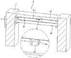
FIG. 1 is a schematic view of the overall structure of a textile fabric inspecting machine;
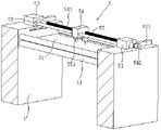
FIG. 2 is a schematic structural view of a discharging mechanism in a textile fabric inspecting machine;
FIG. 3 is a schematic structural view of a dust removing mechanism in a textile fabric inspecting machine;
FIG. 4 is a schematic structural view of an inspection mechanism in a textile fabric inspection machine;
FIG. 5 is a schematic structural view of a marking mechanism in a textile fabric inspection machine;
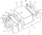
FIG. 6 is a schematic structural view of a cleaning mechanism in a textile fabric inspecting machine;
FIG. 7 is a schematic view of the drying assembly in the cleaning mechanism;
FIG. 8 is a schematic view of the construction of the ironing assembly of the cleaning mechanism;
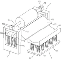
fig. 9 is a schematic structural view of a receiving mechanism in a textile fabric cloth inspecting machine.
In the figure, 1, a frame; 11. a cloth guide roller; 12. a support groove; 13. a material lifting groove; 2. a discharging mechanism; 21. a discharge roller; 22. a support roll; 23. a supporting seat; 24. adjusting the screw rod; 241. adjusting a hand wheel; 25. a material lifting seat; 251. a material lifting cylinder; 26. a material lifting roller; 27. a material lifting plate; 3. a dust removal mechanism; 31. a dust collection plate; 32. a dust suction port; 33. combing a wool roller; 331. a combing motor; 34. a dust storage chamber; 341. a plug cover; 342. a dust outlet; 35. a dust collection pipe; 4. a checking mechanism; 41. a panel; 411. an L-shaped rod; 42. a defect sensor; 43. a lamp panel; 44. a flaw meter counter; 45. a total length meter; 5. a marking mechanism; 51. a support plate; 52. a marker post; 53. a marker holder; 531. marking the cylinder; 54. a marking seat; 541. marking a screw rod; 542. adjusting the motor; 55. marking the handpiece; 551. marking the motor; 6. a cleaning mechanism; 6-1, cleaning the component; 6-2, drying the component; 6-3, an ironing assembly; 61. an ultrasonic cleaning tank; 611. a cloth pressing groove; 612. a cloth pressing seat; 613. a cloth pressing roller; 614. a cloth pressing cylinder; 62. drying box; 621. a cover plate; 622. a material port; 623. heating the brick by infrared rays; 624. a range increasing roller; 625. an electric heating roller; 63. a lower ironing board; 631. an upper ironing board; 632. an ironing board cylinder; 633. a tension roller; 634. a tensioning seat; 635. a tensioning cylinder; 64. a hole plate; 641. a liquid receiving tank; 642. pressing a plate; 643. an extrusion cylinder; 7. a material receiving mechanism; 71. a material receiving roller; 72. a bearing seat; 721. a clamping groove is formed; 722. a limiting block; 73. a blanking roller; 731. a material receiving motor; 74. a blanking seat; 741. a first tension spring; 75. a blanking plate; 8. a material receiving trolley; 81. a base; 82. an arc-shaped plate; 83. a telescopic column; 831. a second tension spring; 9. and a controller.
Detailed Description
The present invention will be described in further detail with reference to the following drawings and examples. It should be understood that the specific embodiments described herein are merely illustrative of the invention and are not intended to limit the invention.
The utility model provides a weaving surface fabric cloth inspection machine, as shown in figure 1, include the frame 1 that sets up along surface fabric direction of feed, be equipped with drop feed mechanism 2 along surface fabric direction of feed in proper order in frame 1, dust removal mechanism 3, inspection machine constructs 4, marking mechanism 5, clearance mechanism 6 and receiving agencies 7, and it is equipped with a plurality of fabric guide rollers 11 that set up along frame 1 width direction between two liang, a plurality of fabric guide rollers 11 along 1 length direction crisscross setting up from top to bottom of frame 1 on frame 1, the surface fabric is the S type and walks around fabric guide rollers 11 and carry forward. Wherein, still be equipped with the controller 9 that is located inspection mechanism 4 one side at frame 1 one side outer wall, each automatic work of mechanism and mutual linkage are controlled through PLC control technology to controller 9, and wherein, PLC control technology is prior art, does not do too much to describe.
As shown in figure 1, a material discharging mechanism 2 is provided with a raw material roll for discharging the fabric to be inspected, a material receiving mechanism 7 is used for winding the inspected fabric to form a finished material roll, and in the process, the fabric sequentially passes through a dust removal mechanism 3, an inspection mechanism 4, a marking mechanism 5 and a cleaning mechanism 6. The dust removal mechanism 3 removes dust, lint and the like on the surface of the fabric, so that the accuracy of the detection result of the detection mechanism 4 is prevented from being influenced; the inspection mechanism 4 inspects the flaws on the surface of the fabric, feeds the result back to the controller 9, judges whether the flaws are irreparable hole flaws or removable stain flaws, and correspondingly controls the marking mechanism 5 or the cleaning mechanism 6 to work according to the judgment result, so as to realize marking of the hole flaws and cleaning of the stain flaws.
The specific structures of the discharging mechanism 2, the dust removing mechanism 3, the inspecting mechanism 4, the marking mechanism 5, the cleaning mechanism 6 and the receiving mechanism 7 are explained in detail in sequence along the fabric feeding direction.
As shown in fig. 1 and 2, the discharging mechanism 2 includes supporting rollers 22 symmetrically disposed on the inner side wall of the frame 1 and located at two ends of the frame 1 in the width direction, the axial direction of the supporting rollers 22 is disposed along the width direction of the frame 1, and a discharging roller 21 coaxially disposed with the supporting rollers 22 and having a raw material roll is clamped between the two supporting rollers 22. When the materials are normally discharged, the supporting roller 22 is coaxially clamped with the discharging roller 21, and the discharging roller 21 is driven to rotate for discharging under the material collecting effect of the material collecting mechanism 7. In order to facilitate the replacement of a new raw material roll after the raw material roll is inspected, the two supporting rollers 22 are slidably mounted on the frame 1 along the axial direction of the two supporting rollers, when the raw material roll needs to be replaced, the two supporting rollers 22 are driven to slide away from each other and are pulled out from the supporting rollers 22, the clamping effect between the two supporting rollers and the discharging roller 21 is removed, and the empty discharging roller 21 can be taken down to replace the new discharging roller 21 with the raw material roll.
As shown in fig. 2, in order to slidably mount the two supporting rollers 22 on the frame 1, a supporting seat 23 is disposed on a side of the two supporting rollers 22 away from each other, and one end of the supporting roller 22 close to the supporting seat 23 is rotatably mounted on the corresponding supporting seat 23. The frame 1 is provided with support grooves 12 arranged along the axial direction of the support rollers 22, and the support seats 23 are slidably mounted in the corresponding support grooves 12. An adjusting screw rod 24 which is in threaded connection with the corresponding supporting seat 23 is positioned and rotatably installed in each supporting groove 12, one end of the adjusting screw rod 24 extends out of the corresponding supporting groove 12 and is positioned outside the machine frame 1, and the adjusting screw rod is connected with an adjusting hand wheel 241 which drives the adjusting screw rod to rotate. The adjusting hand wheel 241 is used for driving the adjusting screw rod 24 to rotate, and under the threaded connection effect of the adjusting screw rod 24 and the supporting seat 23 and the limiting and guiding effect of the supporting groove 12 on the supporting seat 23, the supporting seat 23 is driven to slide in the supporting groove 12, so that the supporting roller 22 is driven to be inserted into or pulled out of the discharging roller 21 in a sliding manner.
As shown in fig. 2, in order to reduce the labor intensity when changing the raw material roll, two parallel lifting rollers 26 are arranged below the discharging roller 21, and the axes of the discharging roller 21 are positioned on the symmetrical plane of the two lifting rollers 26. The two ends of the material lifting roller 26 are respectively provided with a material lifting seat 25, and the end parts of the two material lifting rollers 26 positioned on the same side are positioned and rotatably installed on the same material lifting seat 25. The material lifting groove 13 which is vertically arranged and matched with the material lifting seat 25 is arranged on the frame 1, the material lifting seat 25 is vertically and slidably installed in the corresponding material lifting groove 13, and the material lifting seat is connected with a material lifting cylinder 251 which drives the material lifting cylinder to vertically slide along the material lifting groove 13. As shown in fig. 1 and 2, an obliquely arranged material lifting plate 27 is fixed between the two material lifting seats 25, the material lifting plate 27 is located on one side of the material lifting seats 25 away from the dust removing mechanism 3, and the lower end face of the higher end of the material lifting plate is tangent to the outer wall of the material lifting roller 26 away from the dust removing mechanism 3.
As shown in fig. 2, when a new raw material roll needs to be replaced, the empty discharging roller 21 is taken down from the two supporting rollers 22, the lifting cylinder 251 drives the lifting seat 25 to drive the two lifting rollers 26 to vertically slide downwards until the lower end of the lifting plate 27 abuts against the ground, and then the new raw material roll rolls onto the two lifting rollers 26 along the lifting plate 27 and is placed on the two lifting rollers 26. Then the lifting cylinder 251 drives the lifting seat 25 to move upwards until the discharging roller 21 of the raw material roll is coaxial with the supporting rollers 22, then the adjusting screw rod 24 is driven to rotate by the adjusting hand wheel 241, and the two supporting rollers 22 are driven to be inserted into the end parts of the supporting rollers 22 to be clamped with the end parts of the supporting rollers 22, so that the discharging roller 21 rotates to release the fabric. The structure is simple, the material lifting plate 27 and the material lifting roller 26 are used for feeding the raw material roll, the raw material roll does not need to be lifted to a higher height manually, the raw material roll does not need to be lifted all the time when the supporting roller 22 is driven to move, and the manual labor intensity is greatly reduced.
As shown in fig. 1 and 3, in the present embodiment, the dust removing mechanism 3 includes two dust suction plates 31 disposed along the width direction of the frame 1 and vertically symmetrical, a trumpet-shaped dust suction opening 32 is disposed at a side where the two dust suction plates 31 are close to each other, and a side where the dust suction opening 32 is larger is directed toward the fabric. As shown in fig. 3, the combing rollers 33 are rotatably installed inside the dust suction port 32 along the length direction thereof, the axes of the two combing rollers 33 are located inside the dust suction port 32, but the sides close to each other are located outside the corresponding dust suction port 32, and the combing rollers 33 are connected with a combing motor 331 for driving the combing rollers 33 to rotate. The dust storage cavity 34 is arranged on one side of the dust suction opening 32 on the dust suction plate 31, the dust storage cavity 34 and the dust suction opening 32 are both arranged along the length direction of the dust suction plate 31, a dust suction pipe 35 for communicating the dust storage cavity 34 and the dust suction opening is arranged between the dust storage cavity 34 and the dust suction opening, and one end of the dust storage cavity 34 is provided with a dust outlet 342 with a plug cap 341.
As shown in fig. 1 and 3, the fabric passes between the two combing rollers 33, the combing motor 331 drives the combing rollers 33 to rotate to comb the impurities such as the floating hair on the surface of the fabric, the dust suction pipe 35 sucks the dust on the surface of the fabric and the floating hair cleaned by the combing rollers 33 into the dust storage cavity 34 through the dust suction port 32, and the surface of the fabric is cleaned. Wherein, the dust absorption opening 32 is in a horn shape, so that the dust absorption effect is improved; the dust storage cavity 34 is arranged at one side of the dust suction port 32 and is communicated with the dust suction pipe 35, so that sundries are prevented from falling onto the surface of the fabric when the dust suction pipe 35 stops working. In addition, one end of the dust storage cavity 34 is provided with a dust outlet 342 with a plug cap 341, when the dust storage cavity 34 is filled with a large amount of sundries, the plug cap 341 is taken down to clean the sundries in the dust storage cavity 34 from the dust outlet 342, thereby ensuring the continuous use of the dust storage cavity 34.
As shown in fig. 1 and 4, in the present embodiment, the inspection mechanism 4 includes a panel 41 disposed along the width direction of the rack 1, a defect sensor 42 connected to the controller 9 in a feedback manner is embedded in an upper end surface of the panel 41, a lamp panel 43 located above the panel 41 is disposed on the rack 1, the lamp panel 43 is illuminated toward the panel 41, and the brightness of the lamp panel 43 is adjustable. The fabric penetrates between the panel 41 and the lamp panel 43, the lamp panel 43 shines on the fabric, when holes are formed in the fabric, light can directly penetrate through the fabric and is projected onto the panel 41 to be sensed by the defect sensor 42, the projection of stains on the panel 41 is only dark, the defect sensor 42 judges the position and the type of the defects according to the sensing of shadow brightness, and therefore the position and the type of the defects are fed back to the controller 9, and the controller 9 can correspondingly control the marking mechanism 5 or the cleaning mechanism 6 to work.
In addition, as shown in fig. 4, an L-shaped rod 411 is provided at one end of the panel 41, a movable end of the L-shaped rod 411 parallel to the panel 41 is close to the center of the panel 41, two parallel defect meter 44 and total length meter 45 connected in communication with the controller 9 are provided at the movable end of the L-shaped rod 411, and the defect sensor 42 and the defect meter 44 are linked in communication feedback. As shown in fig. 1 and 4, when the fabric passes through between the panel 41 and the lamp panel 43, the flaw meter 44 and the total length meter 45 are pressed on the upper surface of the fabric, the total length meter 45 works all the time in the moving process of the fabric, and the whole length of the fabric is recorded, so that the excess fabric at the discharging mechanism 2 is judged, and a new raw material roll is timely replaced. When the flaw sensor 42 senses a flaw, the flaw counter 44 starts working and records the forward moving distance of the fabric, so that when the flaw moves to the marking mechanism 5 or the cleaning mechanism 6, the controller 9 controls the fabric to stop conveying and controls the marking mechanism 5 or the cleaning mechanism 6 to work, and the accuracy of processing the position of the flaw is ensured.
As shown in fig. 1 and 5, in the present embodiment, the marking mechanism 5 includes a support plate 51 disposed along the width direction of the frame 1, a marking rod 52 disposed along the width direction of the frame 1 is disposed above the support plate 51, marking frames 53 are disposed at both ends of the marking rod 52, and the marking frames 53 are connected to a marking cylinder 531 for driving the marking frames to slide on the frame 1 along the length direction of the frame 1. A marking screw 541 which is positioned at one side of the marking rod 52 and is parallel to the marking rod 52 is also positioned and rotatably installed between the marking frames 53, and one end of the marking screw 541 is connected with an adjusting motor 542 which drives the marking screw to rotate. The marking rod 52 is sleeved with a marking seat 54 which slides along the length direction of the marking rod, the marking seat 54 is in threaded connection with a marking screw 541, the bottom of the marking seat 54 is provided with an eccentric rotating marking head 55, and the rotating axis of the marking head 55 is vertically arranged and is connected with a marking motor 551 which drives the marking head 55 to eccentrically rotate.
As shown in fig. 4 and 5, the fabric passes through between the supporting plate 51 and the marking head 55, when the defect sensor 42 detects a hole defect and the defect counter 44 determines that the hole defect moves to the marking mechanism 5, the controller 9 controls the marking cylinder 531 to drive the marking frame 53 to move along the length direction of the frame 1 as a whole, the adjusting motor 542 drives the marking screw 541 to rotate, the marking seat 54 is driven to drive the marking head 55 to move along the length direction of the marking rod 52, so that the marking head 55 moves to the hole defect position, and then the marking motor 551 drives the marking head 55 to sew a mark around the hole defect while rotating, so as to mark the hole defect.
In the embodiment, the color of the sewing thread used by the marking head 55 is a contrast color with the color of the fabric, for example, the fabric is white, and the sewing thread is black or striking red, so that the hole flaws are marked more striking, the positions of the holes can be easily determined when the fabric is used, so that the hole flaws can be accurately cut off, and the perfect fabric near the holes can still be used, thereby avoiding the waste of the fabric.
As shown in figures 1 and 6, the cleaning mechanism 6 comprises a cleaning component 6-1 close to the marking mechanism 5, an ironing component 6-3 close to the material receiving mechanism 7 and a drying component 6-2 located between the cleaning component 6-1 and the ironing component 6-3, fabric with stain flaws is cleaned by the cleaning component 6-1 to wash away stains on the surface of the fabric, then the fabric is dried by the drying component 6-2 to prevent the fabric from mildewing easily after being wetted and wound, and finally the fabric is ironed by the ironing component 6-3 to prevent the fabric from forming wrinkles to influence the surface quality.
As shown in fig. 6, in the present embodiment, the cleaning assembly 6-1 includes an ultrasonic cleaning tank 61 disposed along the width direction of the frame 1 and having an open upper end surface, and the ultrasonic cleaning tank 61 contains a cleaning liquid, and the type of the cleaning liquid is selected according to the material of the fabric. The ultrasonic cleaning tank 61 is provided with cloth guide rollers 11 located above the ultrasonic cleaning tank 61 on both sides in the longitudinal direction thereof, and two cloth presser rollers 613 parallel to the cloth guide rollers 11 and located directly above the ultrasonic cleaning tank 61 are provided between the two cloth guide rollers 11. The fabric is wound around the upper side of the fabric guide rollers 11 at the two sides of the ultrasonic cleaning box 61 and is wound around the lower side of the two cloth pressing rollers 613, and the two ends of the two cloth pressing rollers 613 are vertically and slidably mounted on the inner side wall of the ultrasonic cleaning box 61. When the stain defect moves into the ultrasonic cleaning tank 61, the fabric feeding is suspended, the two cloth pressing rollers 613 are driven to move downwards, the fabric is completely pressed below the liquid level of the ultrasonic cleaning tank 61, the ultrasonic cleaning tank 61 works, and the stain defect of the fabric is subjected to ultrasonic cleaning.
As shown in fig. 6, in order to drive the two cloth pressing rollers 613 to slide vertically, two vertically arranged cloth pressing grooves 611 are symmetrically arranged on the inner side walls of the two ends of the ultrasonic cleaning tank 61, a cloth pressing base 612 is vertically and slidably mounted in the cloth pressing grooves 611, the two cloth pressing rollers 613 are positioned at the same end of the same side and rotatably mounted on the same cloth pressing base 612, the upper end surface of the cloth pressing base 612 is always positioned above the liquid level in the ultrasonic cleaning tank 61, and a cloth pressing cylinder 614 which is vertically arranged and is fixedly connected with the upper end surface of the cloth pressing base 612 is fixed on the machine frame 1. The cloth pressing cylinder 614 is used for driving the cloth pressing base 612 to drive the two cloth pressing rollers 613 to slide synchronously, so that the driving structure is simplified, the driving structure is prevented from being in a cleaning solution, and the driving effect on the cloth pressing rollers 613 is ensured.
As shown in fig. 6 and fig. 7, in the present embodiment, the drying assembly 6-2 includes a drying box 62 disposed on the frame 1, the drying box 62 is a cavity structure with a cover plate 621 at an upper end, and two sides of the drying box are respectively provided with a material inlet 622 for feeding and discharging the fabric. A plurality of infrared heating bricks 623 are arranged on five inner walls of the drying box 62, and the whole inside of the drying box 62 is heated by the infrared heating bricks 623. In addition, a plurality of stroke-increasing rollers 624 which are parallel to the cloth guide roller 11 and are arranged in a vertically staggered manner are also arranged in the drying box 62, and electric heating rollers 625 are sleeved outside the stroke-increasing rollers 624. In the abluent surface fabric of ultrasonic cleaning case 61 carried stoving case 62, electric heat roller 625 was walked around to surface fabric S type, realized the stoving to the surface fabric under infrared heating brick 623 and electric heat roller 625' S heating effect, effectively guaranteed the stoving speed and the stoving effect to the surface fabric. The arrangement of the range-increasing roller 624 can increase the travel of the fabric in the drying box 62, improve the drying time of the fabric in the drying box 62, and further improve the drying effect of the fabric.
As shown in fig. 6 and 7, a perforated plate 64 is disposed between the drying box 62 and the ultrasonic cleaning box 61 along the width direction of the frame 1, a liquid receiving groove 641 is disposed below the perforated plate 64, a pressing plate 642 is disposed above the perforated plate 64 in parallel with the perforated plate, a vertically disposed pressing cylinder 643 for driving the pressing plate 642 to vertically slide is fixed to the frame 1, and a piston rod of the pressing cylinder 643 is vertically downward and fixedly connected to the upper end surface of the pressing plate 642. The fabric cleaned by the ultrasonic cleaning box 61 moves above the hole plate 64, the pressing plate 642 is driven by the squeezing cylinder 643 to move vertically downwards, the pressing plate 642 and the hole plate 64 are matched to squeeze the fabric, a part of cleaning liquid on the fabric is squeezed out first, and the flowing cleaning liquid flows into the liquid receiving tank 641 from the holes of the hole plate 64, so that the collection of redundant cleaning liquid is realized. Can alleviate stoving case 62 like this pressure, improve stoving case 62's drying efficiency to avoid the washing liquid to drip everywhere from the surface fabric and trickle, guarantee the clean and tidy of frame 1 surrounding environment.
As shown in fig. 6 and 8, in the present embodiment, the ironing assembly 6-3 includes a lower ironing board 63 disposed along the width direction of the machine frame 1, an upper ironing board 631 parallel to the lower ironing board 63 is disposed above the lower ironing board 63, and an ironing board cylinder 632 is connected to the upper end surface of the upper ironing board 631 and drives the upper ironing board 631 to vertically slide along the machine frame 1. The two sides of the lower ironing plate 63 are also provided with tensioning rollers 633 parallel to the cloth guide roller 11, the two ends of the tensioning rollers 633 are provided with tensioning seats 634 vertically slidably mounted on the frame 1, and a tensioning cylinder 635 for driving the tensioning rollers 633 to vertically slide on the frame 1 is connected below the tensioning seats 634. The fabric is passed over the tensioning roller 633 and between the upper 631 and lower 63 ironing plates.
As shown in fig. 6 and 8, after the fabric in the drying box 62 is dried, the fabric moves between the upper ironing plate 631 and the lower ironing plate 63, the tensioning cylinder 635 and the ironing plate cylinder 632 respectively drive the tensioning roller 633 and the upper ironing plate 631 to vertically move downwards, and the surface of the fabric is ironed by the upper ironing plate 631 and the lower ironing plate 63, so that wrinkles on the surface of the fabric are avoided, and the surface quality of the fabric is ensured. After ironing, the upper ironing plate 631 and the tensioning roller 633 are reset, and the material receiving mechanism 7 is used for rolling materials. Wherein, the tensioning force of surface fabric rolling is guaranteed to tensioning roller 633 normality, guarantees the regularity of surface fabric rolling, and tensioning roller 633 moves down during ironing for the surface fabric has certain relaxation nature, and the last ironing plate 631 of being convenient for flattens the surface fabric, guarantees the effect of ironing.
As shown in fig. 1 and fig. 9, in this embodiment, the material receiving mechanism 7 includes a material receiving roller 71 disposed along the width direction of the frame 1, bearing seats 72 symmetrically disposed at two ends of the material receiving roller 71 and cooperating with the material receiving roller 71 are disposed on the frame 1, a snap-in groove 721 cooperating with the material receiving roller 71 is disposed at the upper end of the bearing seat 72, a limit block 722 having one end rotatably disposed on the upper end surface of the bearing seat 72 is disposed on one side of the snap-in groove 721, and the rotation axis of the limit block 722 is vertically disposed. When the material receiving roller 71 is installed, the clamping groove 721 of the bearing seat 72 is opened by the rotating limiting block 722, the material receiving roller 71 is installed in the bearing seat 72 from the clamping groove 721, and then the rotating limiting block 722 is reset to limit the material receiving roller 71 in the bearing seat 72. When material is taken, the limiting block 722 is only required to be rotated to open the clamping groove 721, and the material receiving roller 71 is lifted out of the bearing seat 72, so that convenience and trouble saving are realized.
As shown in fig. 9, in order to ensure the rotation of the material receiving roller 71 for receiving material, two parallel discharging rollers 73 are arranged below the material receiving roller 71, the axis of the material receiving roller 71 is located on the symmetry plane of the two discharging rollers 73, and the discharging rollers 73 are connected with a material receiving motor 731 for driving the rotation of the discharging rollers 73. The two blanking rollers 73 are positioned and rotatably mounted on the same blanking seat 74 at the end part of the same side, the blanking seat 74 is vertically and slidably mounted on the frame 1, a vertically arranged first tension spring 741 is connected between the bottom of the blanking seat and the frame 1, and in a normal state, the blanking rollers 73 are abutted to the material receiving rollers 71. The fabric passes through the gap between the material receiving roller 71 and the discharging roller 73 and is wound on the material receiving roller 71, the material receiving motor 731 drives the discharging roller 73 to rotate, and the discharging roller 73 rotates to drive the material receiving roller 71 to rotate for receiving the material. Under the action of the first tension spring 741, the blanking roller 73 is always abutted against the outer wall of the finished material roll outside the material receiving roller 71, so that the material receiving regularity of the material receiving roller 71 is ensured.
As shown in fig. 1 and fig. 9, in order to facilitate and save trouble when the winding roller is fully wound with the finished material roll, an obliquely arranged blanking plate 75 is arranged on one side of each of the two blanking seats 74 away from the cleaning mechanism 6, and the lower end surface of the higher end of the blanking plate 75 is tangent to the outer wall of the blanking roller 73 away from the cleaning mechanism 6. As shown in fig. 9, a material receiving trolley 8 is arranged on one side of the lower end of the material discharging plate 75, the material receiving trolley 8 comprises a base 81 with universal wheels, an arc-shaped plate 82 with an inward concave upper end surface is arranged on the base 81, and a plurality of vertically arranged telescopic columns 83 are arranged between the lower end surface of the arc-shaped plate 82 and the upper end surface of the base 81 in a rectangular array manner. A second tension spring 831 is sleeved outside the telescopic column 83, one end of the second tension spring 831 is fixed to the lower end face of the arc-shaped plate 82, and the other end of the second tension spring 831 is fixed to the upper end face of the base 81.
As shown in fig. 9, during material taking, the material receiving roller 71 is lifted up a little distance to take out the material receiving roller 71 from the bearing seat 72, then the finished material roll directly rolls on the arc plate 82 of the material receiving trolley 8 along the material discharging plate 75, after the arc plate 82 receives the finished material roll, the telescopic column 83 and the second tension spring 831 are compressed, the arc plate 82 moves downwards, the material discharging seat 74 drives the material discharging plate 75 to move upwards under the action of the first tension spring 741, so that the material receiving trolley 8 is directly moved to remove the finished material roll, and the material receiving trolley 8 is placed on one side of the material discharging plate 75 again before material discharging. Utilize flitch 75 and receipts material dolly 8 to realize the automatic unloading and receive the material of finished product material book, need not artifical transport, greatly reduce artifical intensity of labour, the arc structure of arc 82 can avoid the finished product material to roll on receiving the material dolly 8 in addition, guarantees to receive the stability of expecting.
The working principle and the using method of the invention are as follows:
raw material loading:the raw material roll rolls along the material lifting plate 27 and is placed on the two material lifting rollers 26, the material lifting seat 25 drives the material lifting rollers 26 to move upwards until the discharging roller 21 and the supporting roller 22 are coaxial, the supporting seat 23 is driven to drive the supporting roller 22 to slide along the axial direction of the supporting roller, and the end part of the supporting roller 22 is inserted into the discharging roller 21 and clamped with the discharging roller 21 so that the discharging roller 21 rotates to release the fabric. The material lifting plate 27 and the material lifting roller 26 are used for feeding the raw material coil, the raw material coil does not need to be lifted to a higher height manually, the raw material coil does not need to be lifted all the time when the supporting roller 22 is driven to move, and the manual labor intensity is greatly reduced.
Fabric dust removal:the fabric passes through between two combing rollers 33, and combing roller 33 rotates and combs impurity such as superficial hair on the fabric surface, and dust absorption pipe 35 inhales the dust on the fabric surface and the superficial hair that combing roller 33 cleared up into dust storage cavity 34 through dust absorption mouth 32, realizes the cleanness to the fabric surface, avoids the surperficial debris of fabric to influence the accuracy of detection mechanism testing result. When the dust storage chamber 34 absorbs a lot of impurities, the plug cap 341 is removed to clean the impurities in the dust storage chamber 34 through the dust outlet 342, so as to ensure the continuous use of the dust storage chamber 34.
And (4) flaw detection:the fabric passes through between the panel 41 and the lamp panel 43, the lamp panel 43 shines on the fabric, and the flaw sensor 42 judges the flaw position and the flaw type according to the induction of shadow brightness, so as to feed back the flaw position and the flaw type to the controller 9. When the flaw sensor 42 senses a flaw, the flaw counter 44 starts working and records the forward moving distance of the fabric, so that when the flaw moves to the marking mechanism 5 or the cleaning mechanism 6, the controller 9 controls the fabric to stop conveying and controls the marking mechanism 5 or the cleaning mechanism 6 to work, and the accuracy of processing the position of the flaw is ensured.
Marking holes:when the defect sensor 42 detects the hole defect and the defect counter 44 determines that the hole defect moves to the marking mechanism 5, the marking frame 53 is driven to move along the length direction of the rack 1, and the marking base 54 is driven to driveThe marking machine head 55 moves along the length direction of the marking rod 52, so that the marking machine head 55 moves to the position of the hole flaw, then the marking motor 551 drives the marking machine head 55 to rotate and sew a striking mark around the hole flaw, the hole flaw is marked, the position of the hole is easy to determine when the fabric is used, the hole flaw is accurately cut, the intact fabric near the hole can be still used, and the waste of the fabric is avoided.
Cleaning stains:when the stain defect moves into the ultrasonic cleaning tank 61, the fabric feeding is suspended, the two cloth pressing rollers 613 are driven to move downwards, the fabric is completely pressed below the liquid level of the ultrasonic cleaning tank 61, the ultrasonic cleaning tank 61 works, and the stain defect of the fabric is cleaned by ultrasonic. The cleaned fabric moves above the hole plate 64, the pressing plate 642 moves vertically downwards to press the fabric in cooperation with the hole plate 64, a part of the cleaning liquid on the fabric is firstly squeezed out, and the effluent cleaning liquid flows into the liquid receiving groove 641 from the holes of the hole plate 64. Then, the fabric enters the drying box 62 and bypasses the electric heating roller 625 in an S-shape, and the fabric is dried under the heating action of the infrared heating brick 623 and the electric heating roller 625. And finally, the fabric moves between the upper ironing plate 631 and the lower ironing plate 63, and the surface of the fabric is ironed by the upper ironing plate 631 and the lower ironing plate 63, so that wrinkles on the surface of the fabric are avoided, and the surface quality of the fabric is ensured.
Blanking of finished products:the fabric passes through the gap between the material receiving roller 71 and the discharging roller 73 and is wound on the material receiving roller 71, the material receiving motor 731 drives the discharging roller 73 to rotate, and the discharging roller 73 rotates to drive the material receiving roller 71 to rotate for receiving the material. When material is taken, the limiting plate is rotated to open the clamping groove 721, the material receiving roller 71 is lifted upwards by a certain distance to be taken out from the bearing seat 72, then the finished material roll directly rolls on the arc-shaped plate 82 of the material receiving trolley 8 along the blanking plate 75 to complete blanking of the finished material roll, and the material receiving trolley 8 can be directly moved to remove the finished material roll. The blanking plate 75 and the material receiving trolley 8 are utilized to automatically blank and receive the finished material rolls, manual carrying is not needed, and the labor intensity of workers is greatly reduced.
While the foregoing description shows and describes the preferred embodiments of the present invention, it is to be understood that the invention is not limited to the forms disclosed herein, but is not to be construed as excluding other embodiments and is capable of use in various other combinations, modifications, and environments and is capable of changes within the scope of the inventive concept as described herein, commensurate with the above teachings, or the skill or knowledge of the relevant art. And that modifications and variations may be effected by those skilled in the art without departing from the spirit and scope of the invention as defined by the appended claims.
Claims (8)
1. The utility model provides a textile fabric cloth inspection machine which characterized in that: the cloth guide device comprises a rack (1) arranged along the fabric feeding direction, wherein a material discharging mechanism (2), a dust removing mechanism (3), an inspection mechanism (4), a marking mechanism (5), a cleaning mechanism (6) and a material receiving mechanism (7) are sequentially arranged on the rack (1) along the fabric feeding direction, a plurality of cloth guide rollers (11) arranged along the width direction of the rack (1) are arranged between every two cloth guide rollers, and the cloth guide rollers (11) are arranged on the rack (1) in an up-and-down staggered manner along the length direction of the rack (1);
the inspection mechanism (4) comprises a panel (41) arranged along the width direction of the rack (1), a flaw sensor (42) is embedded in the upper end face of the panel (41), and a lamp panel (43) which is positioned above the panel (41) and used for polishing the panel (41) is arranged on the rack (1); the flaw sensor (42) is connected with a controller (9) in a communication feedback mode, and the controller (9) is connected with the marking mechanism (5) and the cleaning mechanism (6) in a communication control mode; an L-shaped rod (411) is arranged at one end of the panel (41), one end, far away from the panel (41), of the L-shaped rod (411) is close to the center of the panel (41), two parallel defect meter meters (44) and a total length meter (45) which are in communication connection with the controller (9) are arranged at the end of the L-shaped rod, and the defect sensor (42) is in communication feedback linkage with the defect meter meters (44);
the cleaning mechanism (6) comprises a cleaning component (6-1), a drying component (6-2) and an ironing component (6-3), the cleaning component (6-1) is close to the marking mechanism (5), the ironing component (6-3) is close to the receiving mechanism (7), and the drying component (6-2) is located between the cleaning component (6-1) and the ironing component (6-3);
the cleaning assembly (6-1) comprises an ultrasonic cleaning box (61) arranged along the width direction of the rack (1), two sides of the ultrasonic cleaning box (61) are respectively provided with a cloth guide roller (11) positioned above the ultrasonic cleaning box, and two cloth pressing rollers (613) parallel to the cloth guide rollers are arranged between the two cloth guide rollers (11); the fabric bypasses above the cloth guide rollers (11) on two sides of the ultrasonic cleaning box (61) and bypasses below the two cloth pressing rollers (613), and two ends of the two cloth pressing rollers (613) are vertically and slidably arranged on the inner side wall of the ultrasonic cleaning box (61);
the drying component (6-2) comprises a drying box (62) arranged on the rack (1), the drying box (62) is of a cavity structure with a cover plate (621) at the upper end, and material ports (622) for feeding and discharging the fabric are respectively arranged on two sides of the drying box (62); a plurality of infrared heating bricks (623) are arranged on the inner wall of the drying box (62), a plurality of range-extending rollers (624) which are parallel to the cloth guide roller (11) and are staggered up and down are also arranged in the drying box (62), and electric heating rollers (625) are sleeved outside the range-extending rollers (624);
the ironing assembly (6-3) comprises a lower ironing plate (63) arranged along the width direction of the machine frame (1), an upper ironing plate (631) which is parallel to the lower ironing plate (63) and vertically and slidably mounted on the machine frame (1) is arranged above the lower ironing plate (63), tensioning rollers (633) which are parallel to the cloth guide rollers (11) and vertically and slidably mounted on the machine frame (1) are arranged on two sides of the lower ironing plate (63), and fabric passes over the tensioning rollers (633);
a hole plate (64) arranged along the width direction of the rack (1) is arranged between the drying box (62) and the ultrasonic cleaning box (61), and a liquid receiving groove (641) matched with the hole plate (64) is arranged below the hole plate (64); a pressing plate (642) parallel to the hole plate (64) is arranged above the hole plate, a vertically arranged extrusion cylinder (643) for driving the pressing plate (642) to vertically slide is fixed on the frame (1), and a piston rod of the extrusion cylinder (643) vertically faces downwards and is fixedly connected with the upper end face of the pressing plate (642);
the marking mechanism (5) comprises a supporting plate (51) arranged along the width direction of the rack (1), a marking rod (52) arranged along the width direction of the rack (1) is arranged above the supporting plate (51), and marking frames (53) slidably arranged on the rack (1) along the length direction of the rack (1) are arranged at two ends of the marking rod (52); the marking rod (52) is provided with a marking seat (54) which slides along the length direction of the marking rod, the marking seat (54) is eccentrically and rotatably provided with a marking machine head (55) with a vertically arranged rotating axis, and the color of a sewing thread used by the marking machine head (55) is contrasted with the color of a fabric.
2. A textile fabric cloth inspecting machine according to claim 1, characterized in that: the inner side walls of two ends of the ultrasonic cleaning box (61) are symmetrically provided with vertically arranged cloth pressing grooves (611), cloth pressing seats (612) are vertically and slidably arranged in the cloth pressing grooves (611), and the end parts of the two cloth pressing rollers (613) positioned on the same side are positioned and rotatably arranged on the same cloth pressing seat (612); the upper end face of the cloth pressing seat (612) is always positioned above the liquid level in the ultrasonic cleaning box (61), and a cloth pressing cylinder (614) which is vertically arranged and is fixedly connected with the upper end face of the cloth pressing seat (612) is fixed on the rack (1).
3. The textile fabric cloth inspecting machine according to claim 1, characterized in that: the dust removing mechanism (3) comprises dust collecting plates (31) which are arranged along the width direction of the rack (1) and are symmetrical up and down, and one side of each two dust collecting plates (31) close to each other is provided with a horn-shaped dust collecting opening (32); the dust collection port (32) is internally positioned and rotatably provided with hair combing rollers (33) arranged along the length direction of the dust collection port, and one sides of the two hair combing rollers (33) close to each other are positioned outside the corresponding dust collection port (32); be equipped with on dust absorption board (31) and be located dust storage chamber (34) of dust absorption mouth (32) one side, be equipped with between dust storage chamber (34) and dust absorption mouth (32) with dust absorption pipe (35) of its intercommunication, just dust storage chamber (34) one end is equipped with the play dirt mouth (342) that have gag (341).
4. The textile fabric cloth inspecting machine according to claim 1, characterized in that: the discharging mechanism (2) comprises a discharging roller (21) which is arranged along the width direction of the rack (1) and is provided with a raw material roll, supporting rollers (22) which are positioned at two ends of the discharging roller (21) and coaxially clamped with the discharging roller (21) are arranged on the rack (1), and the two supporting rollers (22) are symmetrically arranged and are axially slidably mounted on the rack (1) along the axial direction; two material lifting rollers (26) which are parallel to the supporting roller (22) and are vertically and slidably mounted on the rack (1) are arranged below the supporting roller (22), the axis of the supporting roller (22) is located on the symmetrical planes of the two material lifting rollers (26), and the raw material roll on the supporting roller (22) is placed on the two material lifting rollers (26).
5. The textile fabric cloth inspecting machine according to claim 4, characterized in that: a material lifting groove (13) which is vertically arranged is formed in the rack (1), a material lifting seat (25) is vertically installed in the material lifting groove (13) in a sliding mode, and the end parts, located on the same side, of the two material lifting rollers (26) are rotatably installed on the same material lifting seat (25) in a positioning mode; an obliquely arranged material lifting plate (27) is fixed between the two material lifting seats (25), the material lifting plate (27) is positioned on one side of the material lifting seats (25) far away from the dust removal mechanism (3), and the lower end face of the higher end of the material lifting plate is tangent to the outer wall of a material lifting roller (26) far away from the dust removal mechanism (3).
6. A textile fabric cloth inspecting machine according to claim 4 or 5, characterized in that: a support groove (12) axially arranged along a support roller (22) is formed in the rack (1), a support seat (23) slidably mounted in the support groove (12) is arranged at one end, close to the support groove (12), of the support roller (22), and the support roller (22) is rotatably mounted on the support seat (23) in a positioning manner; the support groove (12) is internally positioned and rotatably provided with an adjusting screw rod (24) in threaded connection with the support seat (23), one end of the adjusting screw rod (24) extends out of the support groove (12) and is positioned outside the rack (1), and the adjusting screw rod is connected with an adjusting hand wheel (241) for driving the adjusting screw rod to rotate.
7. The textile fabric cloth inspecting machine according to claim 1, characterized in that: the receiving mechanism (7) comprises a receiving roller (71) arranged along the width direction of the rack (1), and bearing seats (72) which are symmetrically arranged at two ends of the receiving roller (71) and matched with the receiving roller (71) are arranged on the rack (1); a clamping groove (721) matched with the material receiving roller (71) is formed in the upper end of the bearing seat (72), a limiting block (722) with one end positioned and rotatably mounted on the upper end face of the bearing seat (72) is arranged on one side of the clamping groove (721), and the rotating axis of the limiting block (722) is vertically arranged; two blanking rollers (73) parallel to the blanking rollers are arranged below the material receiving rollers (71), the axes of the material receiving rollers (71) are positioned on the symmetrical planes of the two blanking rollers (73), and one of the blanking rollers (73) is connected with a material receiving motor (731) for driving the blanking roller to rotate; the two blanking rollers (73) are positioned at the end part of the same side and are rotatably installed on the same blanking seat (74) in a positioning mode, the blanking seat (74) is vertically and slidably installed on the rack (1), a vertically arranged first tension spring (741) is connected between the bottom of the blanking seat and the rack (1), and the blanking rollers (73) are abutted to the material receiving rollers (71) in a normal state.
8. The textile fabric cloth inspecting machine according to claim 7, characterized in that: one side of each blanking seat (74) far away from the cleaning mechanism (6) is provided with a blanking plate (75) which is obliquely arranged, and the lower end surface of the higher end of each blanking plate (75) is tangent to the outer wall of a blanking roller (73) far away from the cleaning mechanism (6); lower flitch (75) lower extreme one side is equipped with receipts material dolly (8), receive material dolly (8) including base (81) that have the universal wheel, be equipped with arc (82) of up end indent on base (81), rectangular array is equipped with flexible post (83) of a plurality of vertical settings between arc (82) lower extreme and base (81) up end, flexible post (83) overcoat is equipped with second tension spring (831), and during the normality, the lower extreme of flitch (75) is close to arc (82) up end and is located its top down.
Priority Applications (1)
| Application Number | Priority Date | Filing Date | Title |
|---|---|---|---|
| CN202210732500.9A CN114803619B (en) | 2022-06-27 | 2022-06-27 | Textile fabric cloth inspecting machine |
Applications Claiming Priority (1)
| Application Number | Priority Date | Filing Date | Title |
|---|---|---|---|
| CN202210732500.9A CN114803619B (en) | 2022-06-27 | 2022-06-27 | Textile fabric cloth inspecting machine |
Publications (2)
| Publication Number | Publication Date |
|---|---|
| CN114803619A CN114803619A (en) | 2022-07-29 |
| CN114803619B true CN114803619B (en) | 2022-09-13 |
Family
ID=82520812
Family Applications (1)
| Application Number | Title | Priority Date | Filing Date |
|---|---|---|---|
| CN202210732500.9A Active CN114803619B (en) | 2022-06-27 | 2022-06-27 | Textile fabric cloth inspecting machine |
Country Status (1)
| Country | Link |
|---|---|
| CN (1) | CN114803619B (en) |
Families Citing this family (4)
| Publication number | Priority date | Publication date | Assignee | Title |
|---|---|---|---|---|
| CN115032201B (en) * | 2022-08-10 | 2022-11-01 | 苏州柔羽智能科技有限公司 | Textile cloth quality on-line measuring device |
| CN116163086A (en) * | 2022-12-30 | 2023-05-26 | 万达集团股份有限公司 | Palm fiber cloth washer recycling equipment |
| CN116203034B (en) * | 2023-04-13 | 2024-08-09 | 江苏祥益纺织科技(集团)有限公司 | Sofa fabric warp knitting cloth inspecting equipment |
| CN116409009B (en) * | 2023-04-20 | 2023-10-31 | 武汉众望包装有限公司 | Production method of super-hydrophobic composite corrugated carton based on nano titanium dioxide |
Family Cites Families (6)
| Publication number | Priority date | Publication date | Assignee | Title |
|---|---|---|---|---|
| CN205023572U (en) * | 2015-09-01 | 2016-02-10 | 新疆天业(集团)有限公司 | Device of rolling up is rewinded to drip irrigation zone |
| CN105424718B (en) * | 2015-11-02 | 2018-08-03 | 东华大学 | A kind of vehicle mirror flaw on-line automatic detection device and method based on double-station |
| CN106915645A (en) * | 2017-03-08 | 2017-07-04 | 扬州市嘉鑫织造实业有限公司 | A kind of batcher with Defect Detection and processing function |
| CN107643294A (en) * | 2017-10-13 | 2018-01-30 | 陕西长岭软件开发有限公司 | A kind of Fabric Defect automatic checkout equipment |
| CN207984342U (en) * | 2018-03-28 | 2018-10-19 | 江苏博虏智能科技有限公司 | A kind of fabric defect marking device |
| CN113494017A (en) * | 2020-04-02 | 2021-10-12 | 上海企力服饰有限公司 | Cloth inspecting machine |
-
2022
- 2022-06-27 CN CN202210732500.9A patent/CN114803619B/en active Active
Also Published As
| Publication number | Publication date |
|---|---|
| CN114803619A (en) | 2022-07-29 |
Similar Documents
| Publication | Publication Date | Title |
|---|---|---|
| CN114803619B (en) | Textile fabric cloth inspecting machine | |
| CN208235116U (en) | A kind of cloth sorting device | |
| CN213113942U (en) | Textile ironing equipment | |
| CN218223584U (en) | Protection film surface defect detection device for OLED | |
| CN112757770A (en) | Screen printing machine | |
| CN210140679U (en) | Novel coating machine main shaft winding device | |
| CN109972377B (en) | Cloth inspecting machine | |
| CN113622111A (en) | Weaving production is with weaving cloth unhairing fine hair device | |
| CN112238029B (en) | Coating device | |
| CN212247491U (en) | Fabric printing and dyeing device capable of conveniently recycling dye | |
| CN211225718U (en) | Cloth inspection machine with auxiliary tensioning device | |
| CN211493294U (en) | Printing device for chemical fiber cloth | |
| CN219326945U (en) | Non-woven fabrics flaw detection rolling integrated device | |
| CN116353195A (en) | Cloth printing processing production line | |
| CN106004025A (en) | Dust collection type weaving and printing device for spinning | |
| CN210765946U (en) | Fabric setting machine | |
| CN211645749U (en) | Integrated device for inspecting and repairing fabric | |
| CN210101027U (en) | Printing device of textile cloth production line | |
| CN114318718A (en) | High-efficient grey cloth cleaning device | |
| CN114561759A (en) | Textile material flushing device with safety protection | |
| CN210506850U (en) | Wrinkle removing device for spinning | |
| CN111721771A (en) | Can prevent multi-functional cloth inspection machine of electrostatic interference perching flow | |
| CN219028884U (en) | Printing device for fabric processing | |
| CN221724819U (en) | Drum-type washing piece production manufacturing device | |
| CN221167173U (en) | Cloth inspection machine with cleaning function |
Legal Events
| Date | Code | Title | Description |
|---|---|---|---|
| PB01 | Publication | ||
| PB01 | Publication | ||
| SE01 | Entry into force of request for substantive examination | ||
| SE01 | Entry into force of request for substantive examination | ||
| GR01 | Patent grant | ||
| GR01 | Patent grant |