CN114799906A - Material rod clamping and pushing linkage device - Google Patents
Material rod clamping and pushing linkage device Download PDFInfo
- Publication number
- CN114799906A CN114799906A CN202210407328.XA CN202210407328A CN114799906A CN 114799906 A CN114799906 A CN 114799906A CN 202210407328 A CN202210407328 A CN 202210407328A CN 114799906 A CN114799906 A CN 114799906A
- Authority
- CN
- China
- Prior art keywords
- pushing
- rod
- trigger
- supporting
- clamping
- Prior art date
- Legal status (The legal status is an assumption and is not a legal conclusion. Google has not performed a legal analysis and makes no representation as to the accuracy of the status listed.)
- Granted
Links
Images


Classifications
-
- B—PERFORMING OPERATIONS; TRANSPORTING
- B23—MACHINE TOOLS; METAL-WORKING NOT OTHERWISE PROVIDED FOR
- B23P—METAL-WORKING NOT OTHERWISE PROVIDED FOR; COMBINED OPERATIONS; UNIVERSAL MACHINE TOOLS
- B23P23/00—Machines or arrangements of machines for performing specified combinations of different metal-working operations not covered by a single other subclass
- B23P23/04—Machines or arrangements of machines for performing specified combinations of different metal-working operations not covered by a single other subclass for both machining and other metal-working operations
-
- B—PERFORMING OPERATIONS; TRANSPORTING
- B23—MACHINE TOOLS; METAL-WORKING NOT OTHERWISE PROVIDED FOR
- B23Q—DETAILS, COMPONENTS, OR ACCESSORIES FOR MACHINE TOOLS, e.g. ARRANGEMENTS FOR COPYING OR CONTROLLING; MACHINE TOOLS IN GENERAL CHARACTERISED BY THE CONSTRUCTION OF PARTICULAR DETAILS OR COMPONENTS; COMBINATIONS OR ASSOCIATIONS OF METAL-WORKING MACHINES, NOT DIRECTED TO A PARTICULAR RESULT
- B23Q7/00—Arrangements for handling work specially combined with or arranged in, or specially adapted for use in connection with, machine tools, e.g. for conveying, loading, positioning, discharging, sorting
- B23Q7/04—Arrangements for handling work specially combined with or arranged in, or specially adapted for use in connection with, machine tools, e.g. for conveying, loading, positioning, discharging, sorting by means of grippers
-
- B—PERFORMING OPERATIONS; TRANSPORTING
- B23—MACHINE TOOLS; METAL-WORKING NOT OTHERWISE PROVIDED FOR
- B23Q—DETAILS, COMPONENTS, OR ACCESSORIES FOR MACHINE TOOLS, e.g. ARRANGEMENTS FOR COPYING OR CONTROLLING; MACHINE TOOLS IN GENERAL CHARACTERISED BY THE CONSTRUCTION OF PARTICULAR DETAILS OR COMPONENTS; COMBINATIONS OR ASSOCIATIONS OF METAL-WORKING MACHINES, NOT DIRECTED TO A PARTICULAR RESULT
- B23Q7/00—Arrangements for handling work specially combined with or arranged in, or specially adapted for use in connection with, machine tools, e.g. for conveying, loading, positioning, discharging, sorting
- B23Q7/06—Arrangements for handling work specially combined with or arranged in, or specially adapted for use in connection with, machine tools, e.g. for conveying, loading, positioning, discharging, sorting by means of pushers
Landscapes
- Engineering & Computer Science (AREA)
- Mechanical Engineering (AREA)
- Physics & Mathematics (AREA)
- Optics & Photonics (AREA)
- Sawing (AREA)
Abstract
The invention belongs to the technical field of lathe machining, and discloses a material bar clamping and pushing linkage device which comprises a base and is characterized in that a bar clamping device, a material cutting and receiving device and a pushing and supporting linkage device are arranged on the base; through the mutual cooperation of the bar clamping device, the cutting and receiving device and the pushing and supporting linkage device, the grinding and rolling continuous operation of a grinding and rolling tool bit is realized, and the coordinated linkage integral linkage control of a plurality of processes of clamping, grinding, rolling, cutting, supporting, pushing and the like of a material bar to be cut is realized, so that the working efficiency is improved; in the material pushing and supporting linkage device, the material supporting mechanism, the linkage trigger mechanism and the material pushing mechanism are mutually matched to realize the smooth, quick and accurate pushing and in-place of the material rods to be cut, so that the next period of working procedures can be conveniently carried out, and the overall processing efficiency is greatly improved.
Description
Technical Field
The invention belongs to the technical field of lathe machining, and particularly relates to a material rod clamping and pushing linkage device.
Background
Grinding is a mechanical processing method for removing materials, and refers to a processing method for cutting off redundant materials on a workpiece by using an abrasive material and a grinding tool. Grinding is one of the more widely used material removal methods.
Rolling is a common process in automobile production and comprises rolling of an inner hole, rolling of a rim, rolling and forming of door frame strips, rolling and forming of frame longitudinal beams, rolling and strengthening and straightening of a crankshaft, rolling and forming of a small-modulus spline shaft, rolling and forming of screws and the like.
Polishing refers to a process of reducing the roughness of the surface of a workpiece by mechanical, chemical or electrochemical action to obtain a bright, flat surface. When the polishing machine works, a wheel made of soft materials such as cloth, leather or wood with abrasive materials is generally used for high-speed rotation to wipe the surface of a workpiece so as to improve the surface smoothness of the workpiece. The conventional polishing machine has a good polishing effect on a plane and a surface having a low curvature, however, when a circumferential surface is polished, uneven polishing occurs, greatly reducing the processing efficiency, and the vibration of the conventional polishing machine also reduces the polishing effect.
The processes all need a device for clamping, fixing and automatically feeding the material rods to be cut so as to ensure that the previous processes can be smoothly, stably and quickly carried out.
Disclosure of Invention
The invention aims to provide a material rod clamping and pushing linkage device, which realizes the stable, rapid and accurate pushing and in-place of a material rod to be cut so as to facilitate the next cycle of working procedures and greatly improve the overall processing efficiency; the technical scheme adopted for achieving the purpose is as follows:
a material bar clamping and pushing linkage device comprises a base, wherein a bar clamping device, a material cutting and receiving device and a pushing and supporting linkage device are arranged on the base;
the bar clamping device comprises a second lead screw sliding table mechanism, a sliding table of the second lead screw sliding table mechanism moves in the front-back direction, a supporting frame is mounted on the sliding table, a vertical rotating shaft is connected in the supporting frame in a rotating mode, the vertical rotating shaft is sequentially divided into an upper threaded section, a smooth section and a lower threaded section from top to bottom, and a second servo motor for providing power for the rotation of the vertical rotating shaft is arranged at the bottom of the supporting frame; the cutting device comprises a supporting frame, and is characterized in that a vertical slideway is arranged on the supporting frame, an upper clamping arm and a lower clamping arm are vertically and slidably connected in the vertical slideway, the tail end of the upper clamping arm is in threaded connection with an upper threaded section, the tail end of the lower clamping arm is in threaded connection with a lower threaded section, an upper arc-shaped clamping plate is arranged at the front end of the upper clamping arm, a lower arc-shaped clamping plate is arranged at the front end of the lower clamping arm, and the upper arc-shaped clamping plate and the lower arc-shaped clamping plate are used for clamping a material bar to be cut;
the cutting and receiving device comprises a linear cutting device and a receiving device, the linear cutting device is used for cutting a material bar to be cut, and the receiving device is used for receiving the cut material plate;
the material pushing and supporting linkage device comprises a linkage trigger mechanism, a material supporting mechanism and a material pushing mechanism, wherein the linkage trigger mechanism comprises a trigger support, a transmission rod is connected in the trigger support in a vertical sliding mode, a trigger rod is connected in the trigger support in a horizontal sliding mode, a horizontal rotating shaft is connected in the rotating mode, a steering gear is fixed on the horizontal rotating shaft, teeth are arranged on the transmission rod, the trigger rod and the horizontal rotating shaft, namely the transmission rod is connected with the horizontal rotating shaft in a meshing mode, the steering gear is connected with the trigger rod in a meshing mode, a contact rod is arranged on a lower clamping arm, when the lower clamping arm moves downwards, the contact rod presses the transmission rod downwards, the transmission rod drives the horizontal rotating shaft to rotate, the steering gear drives the trigger rod to move, the trigger rod triggers the material supporting mechanism to move, and meanwhile, the bottom of the transmission rod moves downwards to trigger the material pushing mechanism to move.
Preferably, a support seat is arranged in the middle of the support frame, the vertical rotating shaft penetrates through the support seat and is rotatably connected with the support seat, an upper threaded section and a smooth section of the vertical rotating shaft are positioned above the support seat, and a lower threaded section is positioned below the support seat; and a pressure spring is sleeved on the upper threaded section above the upper clamping arm, one end of the pressure spring abuts against the tail end of the upper clamping arm, and the other end of the pressure spring abuts against a supporting frame at the top of the upper threaded section.
Preferably, be equipped with the screw thread regulation pole under on the centre gripping arm, be equipped with the bar hole that sets up along length direction on the screw thread regulation pole, sliding connection has two regulation poles in the bar hole, all is equipped with down the arc grip block on two regulation poles, all is equipped with adjusting nut in the left and right sides and upper and lower both sides of adjusting the pole, adjusting nut and screw thread regulation pole threaded connection.
Preferably, the material supporting mechanism comprises a material supporting support, a material supporting rod is connected in the material supporting support in a vertical sliding mode, a spring used for pushing the material supporting rod to pop up is arranged at the bottom of the material supporting rod, an arc-shaped material supporting plate is arranged at the top of the material supporting rod, a spring button is arranged on the material supporting support, and when the spring button is triggered by a trigger rod, the material supporting rod pops up under the action of the spring to support a material rod to be cut in a lifting mode; when the trigger rod is separated from the spring button, the material supporting rod can be reset by manually pressing down the material supporting rod.
Preferably, the pushing mechanism comprises a pushing support, a pushing transmission rod is connected in the pushing support in a vertical sliding manner, a pushing trigger rod is connected in the pushing support in a left-right sliding manner, and a horizontal rotating shaft is rotatably connected; a balance type swing rod is arranged between the linkage trigger mechanism and the material pushing transmission rod, one end of the balance type swing rod is hinged with the bottom of the transmission rod, the other end of the balance type swing rod is hinged with the bottom of the material pushing transmission rod, and a return spring is arranged at one end of the balance type swing rod.
Preferably, the arc-shaped material supporting plate comprises an arc-shaped plate with an upward opening, and a positioning plate is arranged on the side surface of the arc-shaped plate.
Preferably, still include the material pushing auxiliary mechanism, the material pushing auxiliary mechanism includes the framework, sliding connection has the step slider about in the framework, right-hand member fixedly connected with at the step slider is used for promoting the cross that waits to cut the material stick and pushes away the frame, be equipped with the recess at step slider left end, be equipped with multistage step on the relative inner wall in the recess, the multistage step of both sides is the symmetric distribution, and the distance between the multistage step of both sides reduces step by step from left to right, sliding connection has the draw runner about at the framework left end, the draw runner right-hand member stretches into in the recess, be equipped with two guide bars at the draw runner right-hand member symmetry, sliding connection has the pushing arm on the guide bar, the cover is equipped with the spring on the guide bar between pushing arm and the draw runner, under the pressure effect of spring, the pushing arm pushes up and leans on corresponding multistage step.
Preferably, a connecting rod extending out of the groove is arranged on the pushing arm, and the left end of the sliding strip is connected with the pushing trigger rod.
The invention has the following beneficial effects: (1) through the mutual cooperation of the bar clamping device C, the material cutting and receiving device A and the material pushing and supporting linkage device D, the continuous grinding and rolling operation of the grinding and rolling cutter head B10 is realized, the coordinated linkage and integral linkage control of a plurality of processes of clamping, grinding, rolling, cutting, material supporting, material pushing and the like of the material bar C21 to be cut is realized, and the working efficiency is improved.
(2) In the bar clamping device C, the quick clamping and releasing of the bar C21 to be cut are realized by arranging different thread sections and smooth sections on a vertical rotating shaft, and the overall structure is compact; meanwhile, the left side, the right side, the upper side and the lower side of the adjusting rod are respectively provided with an adjusting nut, and the adjusting nuts are in threaded connection with the threaded adjusting rod, so that the free adjustment of the adjusting rod in the up-down and left-right directions is realized; simultaneously, bar clamping device through the coordination of two private clothes motors, can reciprocate about in processing.
(3) In the material pushing and supporting linkage device D, the material supporting mechanism D1, the linkage trigger mechanism D2 and the material pushing mechanism D3 are mutually matched to realize the smooth, quick and accurate pushing and in-place of the material rod C21 to be cut, so that the next period of working procedures can be conveniently carried out, and the overall processing efficiency is greatly improved.
Drawings
FIG. 1 is a schematic perspective view of the present invention;
FIG. 2 is a second schematic perspective view of the present invention;
FIG. 3 is a schematic perspective view of a bar clamping device;
FIG. 4 is an enlarged schematic view of a portion G of FIG. 3;
FIG. 5 is a schematic view of a vertical structure of the receiving device;
FIG. 6 is a schematic view of the body structure of the pushing and supporting linkage device;
FIG. 7 is an enlarged view of the portion K in FIG. 6;
FIG. 8 is a perspective view of the pushing assistance mechanism;
FIG. 9 is a second schematic perspective view of the pushing assisting mechanism;
fig. 10 is a sectional view of the pusher assist mechanism taken along the direction H-H.
Detailed Description
The invention is further described below with reference to the accompanying drawings.
As shown in fig. 1 and fig. 2, a grinding and rolling apparatus capable of continuous operation comprises a base 1, a bar clamping device C, a material cutting and receiving device a and a material pushing and supporting linkage device D are mounted on the base 1;
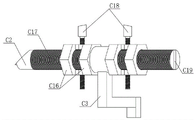
as shown in fig. 3, the bar clamping device C includes a second screw sliding table mechanism C14, a sliding table C20 of the second screw sliding table mechanism C14 moves in the front-back direction, a support frame C1 is mounted on the sliding table C20, a vertical rotating shaft is rotatably connected in the support frame C1, the vertical rotating shaft is sequentially divided into an upper threaded section C8, a smooth section C9 and a lower threaded section C11 from top to bottom, and a second servo motor C13 for providing power for the rotation of the vertical rotating shaft is arranged at the bottom of the support frame C1; a vertical slideway is arranged on the supporting frame C1, an upper clamping arm C6 and a lower clamping arm C2 are connected in the vertical slideway in an up-and-down sliding manner, the tail end of the upper clamping arm C6 is in threaded connection with an upper threaded section C8, the tail end of the lower clamping arm C2 is in threaded connection with a lower threaded section C11, an upper arc-shaped clamping plate C4 is arranged at the front end of the upper clamping arm C6, a lower arc-shaped clamping plate C5 is arranged at the front end of the lower clamping arm C2, and the upper arc-shaped clamping plate C4 and the lower arc-shaped clamping plate C5 are used for clamping a material rod C21 to be cut;
as shown in fig. 1, fig. 2 and fig. 5, the material cutting and receiving device a includes a wire cutting device a1 and a material receiving device a2, the wire cutting device a21 is used for cutting a material rod C21 to be cut, and the material receiving device a2 is used for receiving a cut material plate; in this embodiment, the material receiving device a2 may have a structure, where the material receiving device a2 includes a support a27, a support plate a24 and a fourth servo motor a26 are fixed to the support a27, the support plate a24 is slidably connected to a material receiving plate a22 through a guide rod a23, a threaded rod a21 is rotatably connected to the support plate a24, the threaded rod a21 penetrates through the support plate a24 and is in threaded connection with the support plate a24, and the threaded rod a21 is in transmission connection with the fourth servo motor a26 through a bevel gear a 25.
As shown in fig. 1, 2, 6 and 7, in order to realize the automatic linkage action of supporting and pushing after the cutting is completed, the device further comprises a supporting and pushing linkage device D, the supporting and pushing linkage device D comprises a linkage trigger mechanism D2, a supporting mechanism D1 and a pushing mechanism D3, wherein the linkage trigger mechanism D2 comprises a trigger support D21, a transmission rod D25 is connected in the trigger support D21 in a vertical sliding manner, a trigger rod D22 is connected in a horizontal sliding manner and a horizontal rotating shaft D24 is connected in a rotating manner, a steering gear D26 is fixed on the horizontal rotating shaft D24, teeth are arranged on the transmission rod D25, the trigger rod D22 and the horizontal rotating shaft 695d 2, namely, the transmission rod D25 is connected with the horizontal rotating shaft D24 in a meshing manner, the steering gear D26 is connected with the trigger rod D22 in a meshing manner, a contact rod C3 is arranged on the lower clamping arm C2, and when the lower clamping arm C2 moves downwards, the contact rod C3 presses the transmission rod D25 downwards, the transmission rod D25 drives the horizontal rotating shaft D24 to rotate, the steering gear D24 drives the trigger rod D22 to move, the trigger rod D22 triggers the material supporting mechanism D1 to act, and meanwhile, the bottom of the transmission rod D25 moves downwards to trigger the material pushing mechanism D3 to act.
As shown in fig. 3 and 4, a support seat C10 is provided at the middle of the support frame C16, the vertical rotating shaft passes through the support seat C10 and is rotatably connected with the support seat C10, an upper threaded section C8 and a smooth section C9 of the vertical rotating shaft are located above the support seat C10, and a lower threaded section C11 is located below the support seat C10; a compression spring C7 is sleeved on the upper threaded section C8 above the upper clamping arm C6, one end of the compression spring C7 abuts against the tail end of the upper clamping arm C6, and the other end of the compression spring C7 abuts against a supporting frame C1 at the top of the upper threaded section C8.
On the other hand, be equipped with screw thread adjusting lever C17 on centre gripping arm C2 down, be equipped with the bar hole C19 that sets up along length direction on screw thread adjusting lever C17, sliding connection has two regulation poles C18 in bar hole C19, arc grip block C5 under all being equipped with on two regulation poles C18, all be equipped with adjusting nut C16 in regulation pole C18 both sides, adjusting nut C18 and screw thread adjusting lever C17 threaded connection, just so can adjust the distance between two regulation poles C18 through two adjusting nut C16, with the waiting to cut material stick C21 of adaptation different diameters.
The material supporting mechanism D1 comprises a material supporting support D12, a material supporting rod D13 is connected in the material supporting support D12 in a vertical sliding mode, a spring D11 used for pushing the material supporting rod D13 to pop up is arranged at the bottom of the material supporting rod D13, an arc-shaped material supporting plate D16 is arranged at the top of the material supporting rod D13, a spring button D14 is arranged on the material supporting support D12, and when the spring button is triggered by a trigger rod D22, the material supporting rod D13 pops up under the action of the spring D11 to support a material rod C21 to be cut; when the trigger lever is disengaged from the button of the spring D14, the material supporting rod D13 can be manually pressed downwards to reset.
Further, the arc material supporting plate D16 comprises an arc plate with an upward opening, and a positioning plate D15 is arranged on the side surface of the arc plate, so that the material rod C21 to be cut is pushed forwards and is pushed to the position by abutting against the positioning plate D15.
The pushing mechanism D3 comprises a pushing support D36, a pushing transmission rod D33 is connected in the pushing support D36 in a vertical sliding manner, a pushing trigger rod D35 is connected in a left-right sliding manner, and a horizontal rotating shaft D34 is connected in a rotating manner, two steering gears D37 and D39 are fixed on the horizontal rotating shaft D34, teeth are arranged on both the pushing transmission rod D33 and the pushing trigger rod D35, namely the pushing transmission rod D33 is meshed with the gear D37 on the horizontal rotating shaft D34, and the steering gear D39 is meshed with the pushing trigger rod D35; a balance type swing rod D32 is arranged between the linkage triggering mechanism D2 and the material pushing transmission rod D33, one end of the balance type swing rod D32 is hinged to the bottom of the transmission rod D25, the other end of the balance type swing rod D32 is hinged to the bottom of the material pushing transmission rod D33, and a return spring D31 is arranged at one end of the balance type swing rod D32.
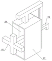
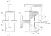
As shown in fig. 8, 9 and 10, the utility model also comprises a pushing auxiliary mechanism E, which comprises a frame E7, a step slider E8 is connected in the frame body E7 in a left-right sliding way, a cross-shaped pushing frame E6 used for pushing a material rod C21 to be cut is fixedly connected at the right end of the step slider E8, the left end of the step slide block E8 is provided with a groove, the opposite inner wall in the groove is provided with a multi-step E5, the multi-step E5 at the two sides are symmetrically distributed, the distance between the multi-step E5 at the two sides is gradually reduced from left to right, a slide bar E4 is connected at the left end of the frame body E7 in a left-right sliding way, the right end of the slide bar E4 extends into the groove, two guide rods are symmetrically arranged at the right end of the slide bar E4, a push arm E1 is connected on the guide rods in a sliding way, a spring E3 is sleeved on the guide rod between the pushing arm E1 and the slide bar E4, and under the pressure of the spring E3, the pushing arm E1 is abutted against the corresponding multi-stage step E5.
As shown in fig. 3, in order to ensure that the relative position between the pushing assisting mechanism E and the material rod C21 to be cut remains unchanged, so as to push the material rod C21 to be cut more accurately and stably, the pushing assisting mechanism E may be fixed on the upper clamping arm C6.
In order to reset the two pushing arms E1 so as to push a new material stick C21 to be cut, and perform the next periodic action, a connecting rod E2 extending out of the groove is arranged on the pushing arm E1, and the left end of the sliding strip E4 is connected with a material pushing trigger rod D35.
When the invention works, as shown in fig. 1, fig. 2, fig. 3 and fig. 4, firstly, a billet C21 to be cut is fixed on a billet clamping device C, and the concrete steps are as follows: the second servo motor C13 drives the vertical rotating shaft to rotate, the upper clamping arm C6 and the lower clamping arm C2 are driven by the upper threaded section C8 and the lower threaded section C11 to move downwards, when the upper clamping arm C6 moves downwards to the smooth section C9 and does not move downwards, the lower clamping arm C2 continues to move downwards so as to open the upper arc-shaped clamping plate C4 and the lower arc-shaped clamping plate C5, two adjusting nuts C16 are adjusted according to the diameter of the bar C21 to be cut so as to adjust the distance between the two adjusting rods C18, the bar C21 to be cut is placed on the two lower arc-shaped clamping plates C5, the tail of the bar C21 to be cut is abutted against the cross push frame E6, then the vertical rotating shaft is rotated reversely, the lower clamping arm C2 carries the bar C21 to be cut to move upwards, after the upper arc-shaped clamping plate C4 is abutted, the upper clamping arm C21 is further clamped after the upper threaded section C8 is connected with the lower clamping arm C2 continuing to be cut under the pressure of the pressure spring C7, and then the upper clamping arm C6, the material rod C21 to be cut and the lower clamping arm C2 are integrally lifted to a proper height, and finally the servo motor C15 acts to drive the sliding table C20 and the whole body on the sliding table to move back and forth to a proper position until the adjustment is finished.
After the above-mentioned process, grind, roll extrusion, cutting through the lathe area grinding rolling tool to expect stick C21 end face to cut, grind, roll extrusion process after expecting stick C21 end face to cut, roll extrusion process, carry out blank and connect the material process, as shown in fig. 1, fig. 2 and fig. 5, linear cutting device A1 can adopt existing equipment, adopt the linear cutting technique to cut off the end face after grinding, roll extrusion processing, at this moment, fourth servo motor A26 action drive threaded rod A21 rotates thereby drive and connect flitch A22 to stretch out fast and catch the product thin slice that cuts off.
After the material cutting and receiving process is finished, the material bar C21 to be cut is pushed forward step by step through the material pushing and supporting linkage device D so as to carry out grinding, rolling and cutting operations of the next cycle period. Firstly, a second servo motor C13 drives a vertical rotating shaft to rotate, an upper clamping arm C6, a material rod C21 to be cut and a lower clamping arm C2 integrally move downwards under the driving of an upper thread section C8 and a lower thread section C11, when the upper clamping arm C6 moves downwards to a smooth section C9, the upper clamping arm C2 does not move downwards, the lower clamping arm C2 continues to move downwards so as to open an upper arc-shaped clamping plate C4 and a lower arc-shaped clamping plate C5, at the moment, a contact rod C3 is pressed on a transmission rod D25, the transmission rod D25 moves downwards to drive a trigger rod D22 to extend out and press on a spring button D14, and a material supporting rod D13 is popped upwards under the action of a spring D11 to support the material rod C21 to be cut; when the trigger lever is disengaged from the button of the spring D14, the material supporting rod D13 can be manually pressed downwards to reset. On the other hand, the transmission rod D25 moves downwards, one end of the balance swing rod D32 is pressed downwards, the pushing transmission rod D33 is pushed to move upwards, the pushing trigger rod D35 is driven to extend out, the pushing trigger rod D35 is connected with the sliding strip E4, as shown in the figures 8 to 10, the sliding strip E4 is driven to push forwards for a certain distance, the sliding strip E4 pushes the step slider E8 rightwards, the cross-shaped pushing frame E6 pushes the to-be-cut rod C21 forwards to a proper position, or the to-be-cut rod C21 is pushed to the position of the positioning plate D15, namely the working position is pushed.
When the material bar C21 to be cut is pushed to the right position, the upper clamping arm C6, the material bar C21 to be cut and the lower clamping arm C2 move upwards to reset integrally, the material supporting rod D13, the transmission rod D25 and the sliding strip E4 are pushed to reset under the action of the reset spring D31, and in the process that the sliding strip E4 retracts to reset, the pushing arms E1 on the two sides are lifted by one step, so that the pushing of the next period is not influenced.
In this embodiment, the pushing assisting mechanism E may also be fixedly installed at the top of the pushing mechanism D3, and the connecting end D38 of the pushing triggering lever D35 is directly and fixedly connected to the slide bar E4. To reduce the hard contact between the trigger lever D22 and the spring button D14, a resilient contact D23 is provided at the end of the trigger lever D22.
Finally, it should be noted that: the above examples are only intended to illustrate the technical solution of the present invention, but not to limit it; although the present invention has been described in detail with reference to the foregoing embodiments, it will be understood by those of ordinary skill in the art that: it is to be understood that modifications may be made to the technical solutions described in the foregoing embodiments, or equivalents may be substituted for some of the technical features thereof, but such modifications or substitutions do not depart from the spirit and scope of the technical solutions of the embodiments of the present invention.
Claims (8)
1. A material bar clamping and pushing linkage device comprises a base and is characterized in that a bar clamping device, a material cutting and receiving device and a pushing and supporting linkage device are mounted on the base;
the bar clamping device comprises a second lead screw sliding table mechanism, a sliding table of the second lead screw sliding table mechanism moves in the front-back direction, a supporting frame is mounted on the sliding table, a vertical rotating shaft is connected in the supporting frame in a rotating mode, the vertical rotating shaft is sequentially divided into an upper threaded section, a smooth section and a lower threaded section from top to bottom, and a second servo motor for providing power for the rotation of the vertical rotating shaft is arranged at the bottom of the supporting frame; the cutting device comprises a supporting frame, and is characterized in that a vertical slideway is arranged on the supporting frame, an upper clamping arm and a lower clamping arm are vertically and slidably connected in the vertical slideway, the tail end of the upper clamping arm is in threaded connection with an upper threaded section, the tail end of the lower clamping arm is in threaded connection with a lower threaded section, an upper arc-shaped clamping plate is arranged at the front end of the upper clamping arm, a lower arc-shaped clamping plate is arranged at the front end of the lower clamping arm, and the upper arc-shaped clamping plate and the lower arc-shaped clamping plate are used for clamping a material bar to be cut;
the cutting and receiving device comprises a linear cutting device and a receiving device, the linear cutting device is used for cutting a material bar to be cut, and the receiving device is used for receiving the cut material plate;
the material pushing and supporting linkage device comprises a linkage trigger mechanism, a material supporting mechanism and a material pushing mechanism, wherein the linkage trigger mechanism comprises a trigger support, a transmission rod is connected in the trigger support in a vertical sliding mode, a trigger rod is connected in the trigger support in a horizontal sliding mode, a horizontal rotating shaft is connected in the rotating mode, a steering gear is fixed on the horizontal rotating shaft, teeth are arranged on the transmission rod, the trigger rod and the horizontal rotating shaft, namely the transmission rod is connected with the horizontal rotating shaft in a meshing mode, the steering gear is connected with the trigger rod in a meshing mode, a contact rod is arranged on a lower clamping arm, when the lower clamping arm moves downwards, the contact rod presses the transmission rod downwards, the transmission rod drives the horizontal rotating shaft to rotate, the steering gear drives the trigger rod to move, the trigger rod triggers the material supporting mechanism to move, and meanwhile, the bottom of the transmission rod moves downwards to trigger the material pushing mechanism to move.
2. The material bar clamping and pushing linkage device as claimed in claim 1, wherein a support seat is provided at the middle part of the support frame, the vertical shaft passes through the support seat and is rotatably connected with the support seat, an upper threaded section and a smooth section of the vertical shaft are located above the support seat, and a lower threaded section is located below the support seat; and a pressure spring is sleeved on the upper threaded section above the upper clamping arm, one end of the pressure spring abuts against the tail end of the upper clamping arm, and the other end of the pressure spring abuts against a supporting frame at the top of the upper threaded section.
3. A bar clamping and pushing linkage as claimed in claim 2, wherein the lower clamping arm has a threaded rod, the threaded rod has a strip-shaped hole along the length thereof, two adjusting rods slidably connected in the strip-shaped hole, the two adjusting rods each have a lower arc-shaped clamping plate, and the left and right sides and upper and lower sides of the adjusting rod have adjusting nuts threadedly connected to the threaded rod.
4. The material bar clamping and pushing linkage device according to claim 2, wherein the material supporting mechanism comprises a material supporting support, a material supporting rod is connected in the material supporting support in a vertical sliding manner, a spring for pushing the material supporting rod to pop up is arranged at the bottom of the material supporting rod, an arc-shaped material supporting plate is arranged at the top of the material supporting rod, a spring button is arranged on the material supporting support, and when the spring button is triggered by a trigger rod, the material supporting rod pops up under the action of the spring to support the material bar to be cut; when the trigger rod is separated from the spring button, the material supporting rod can be reset by manually pressing down the material supporting rod.
5. The material bar clamping and pushing linkage device as claimed in any one of claims 1 to 4, wherein the pushing mechanism comprises a pushing support, a pushing transmission rod is connected in the pushing support in a vertical sliding manner, a pushing trigger rod is connected in the pushing support in a left-right sliding manner, a horizontal rotating shaft is rotatably connected, two steering gears are fixed on the horizontal rotating shaft, teeth are arranged on the pushing transmission rod and the pushing trigger rod, namely the pushing transmission rod is meshed with a gear on the horizontal rotating shaft, and the steering gears are meshed with the pushing trigger rod; a balance type swing rod is arranged between the linkage trigger mechanism and the material pushing transmission rod, one end of the balance type swing rod is hinged to the bottom of the transmission rod, the other end of the balance type swing rod is hinged to the bottom of the material pushing transmission rod, and a return spring is arranged at one end of the balance type swing rod.
6. The material bar clamping and pushing linkage device as claimed in claim 5, wherein the arc-shaped material supporting plate comprises an arc-shaped plate with an upward opening, and a positioning plate is arranged on the side surface of the arc-shaped plate.
7. The material bar clamping and pushing linkage device as claimed in claim 5, further comprising a pushing auxiliary mechanism, wherein the pushing auxiliary mechanism comprises a frame body, a step slide block is connected in the frame body in a left-right sliding way, a cross-shaped pushing frame used for pushing a material bar to be cut is fixedly connected at the right end of the step slide block, the left end of the step slide block is provided with a groove, the opposite inner walls in the groove are provided with multi-stage steps, the multi-stage steps at two sides are symmetrically distributed, and the distance between the multi-stage steps at two sides is gradually reduced from left to right, the left end of the frame body is connected with a slide bar in a left-right sliding way, the right end of the slide bar extends into the groove, two guide rods are symmetrically arranged at the right end of the slide bar, the guide rod is connected with a push arm in a sliding mode, a spring is sleeved on the guide rod between the push arm and the slide bar, and the push arm abuts against the corresponding multistage step under the pressure action of the spring.
8. The material bar clamping, pushing and supporting linkage device as claimed in claim 7, wherein a connecting rod extending out of the groove is arranged on the pushing arm, and the left end of the sliding strip is connected with the pushing trigger rod.
Priority Applications (1)
| Application Number | Priority Date | Filing Date | Title |
|---|---|---|---|
| CN202210407328.XA CN114799906B (en) | 2022-04-19 | 2022-04-19 | Material rod clamping and pushing linkage device |
Applications Claiming Priority (1)
| Application Number | Priority Date | Filing Date | Title |
|---|---|---|---|
| CN202210407328.XA CN114799906B (en) | 2022-04-19 | 2022-04-19 | Material rod clamping and pushing linkage device |
Publications (2)
| Publication Number | Publication Date |
|---|---|
| CN114799906A true CN114799906A (en) | 2022-07-29 |
| CN114799906B CN114799906B (en) | 2023-02-03 |
Family
ID=82536534
Family Applications (1)
| Application Number | Title | Priority Date | Filing Date |
|---|---|---|---|
| CN202210407328.XA Active CN114799906B (en) | 2022-04-19 | 2022-04-19 | Material rod clamping and pushing linkage device |
Country Status (1)
| Country | Link |
|---|---|
| CN (1) | CN114799906B (en) |
Citations (7)
| Publication number | Priority date | Publication date | Assignee | Title |
|---|---|---|---|---|
| GB745278A (en) * | 1953-11-05 | 1956-02-22 | Carver & Company Engineers Ltd | Improved means for transversely cutting bars, tubes, strips or the like |
| CN108672610A (en) * | 2018-05-19 | 2018-10-19 | 芜湖七创工业设计有限公司 | The automatic cutting processing method of the bars such as reinforcing bar, sunpender applied to building trade |
| CN109877655A (en) * | 2018-02-16 | 2019-06-14 | 合肥雅观匠道科技有限公司 | The orientation conveying cutting of rodlike construction material and the automatic edge-chamfering method of section |
| CN112476648A (en) * | 2020-11-06 | 2021-03-12 | 黄国春 | Automatic cutting machine for wood bar stripes |
| CN113146255A (en) * | 2021-04-23 | 2021-07-23 | 无锡市同维机电制造有限公司 | Copper bar saw cutting and skin turning assembly line and copper bar saw cutting and skin turning method thereof |
| CN113635095A (en) * | 2021-08-04 | 2021-11-12 | 安徽宝立华机械设备有限公司 | Cutting machine is used in oil drill pipe processing |
| CN214977431U (en) * | 2021-06-09 | 2021-12-03 | 杭州兴发弹簧有限公司 | Grinding tip clamping device for subway spring bar |
-
2022
- 2022-04-19 CN CN202210407328.XA patent/CN114799906B/en active Active
Patent Citations (7)
| Publication number | Priority date | Publication date | Assignee | Title |
|---|---|---|---|---|
| GB745278A (en) * | 1953-11-05 | 1956-02-22 | Carver & Company Engineers Ltd | Improved means for transversely cutting bars, tubes, strips or the like |
| CN109877655A (en) * | 2018-02-16 | 2019-06-14 | 合肥雅观匠道科技有限公司 | The orientation conveying cutting of rodlike construction material and the automatic edge-chamfering method of section |
| CN108672610A (en) * | 2018-05-19 | 2018-10-19 | 芜湖七创工业设计有限公司 | The automatic cutting processing method of the bars such as reinforcing bar, sunpender applied to building trade |
| CN112476648A (en) * | 2020-11-06 | 2021-03-12 | 黄国春 | Automatic cutting machine for wood bar stripes |
| CN113146255A (en) * | 2021-04-23 | 2021-07-23 | 无锡市同维机电制造有限公司 | Copper bar saw cutting and skin turning assembly line and copper bar saw cutting and skin turning method thereof |
| CN214977431U (en) * | 2021-06-09 | 2021-12-03 | 杭州兴发弹簧有限公司 | Grinding tip clamping device for subway spring bar |
| CN113635095A (en) * | 2021-08-04 | 2021-11-12 | 安徽宝立华机械设备有限公司 | Cutting machine is used in oil drill pipe processing |
Also Published As
| Publication number | Publication date |
|---|---|
| CN114799906B (en) | 2023-02-03 |
Similar Documents
| Publication | Publication Date | Title |
|---|---|---|
| CN110394857B (en) | Square wood processing device | |
| CN206997878U (en) | Turbine Blade Machining copying planer | |
| CN217832096U (en) | Precise die forging is with side cut equipment that can multiaspect process | |
| CN211661498U (en) | Cutting device of copper bar hydraulic drawing machine | |
| CN2902508Y (en) | Metal plate material digital control spinning machine | |
| CN114799906B (en) | Material rod clamping and pushing linkage device | |
| CN219819183U (en) | Be used for material feeding unit for metal product production | |
| CN218656319U (en) | Punch press with guide structure | |
| CN114871890A (en) | Deburring equipment for machining mechanical parts | |
| CN115319598A (en) | Polishing device for hot-work die steel | |
| CN210256327U (en) | Board separator for improving board separation stability of circuit board | |
| CN112517692A (en) | Metal bending and cutting method | |
| CN112091650A (en) | Machine tool for mechanical finish machining | |
| CN112176123A (en) | Quantitative cutting equidistant punching device for leather products | |
| CN219946423U (en) | Plastic cutting machine convenient to position | |
| CN220006019U (en) | Automatic lathe adjusting mechanism | |
| CN220903459U (en) | Automobile foot pad corner trimming machine | |
| CN216397581U (en) | Rib tearing tool for aluminum profile | |
| CN218340721U (en) | Plate slotting bending machine | |
| CN220533125U (en) | Sawing machine feeding frame and sawing machine | |
| CN219401797U (en) | High-precision plate bending arc die | |
| CN219786252U (en) | Stamping die convenient to deburring location | |
| CN219503799U (en) | Plate shearing machine for steel structure machining | |
| CN219924720U (en) | Auxiliary limiting assembly of hydraulic plate shearing machine | |
| CN220597967U (en) | Trimming device |
Legal Events
| Date | Code | Title | Description |
|---|---|---|---|
| PB01 | Publication | ||
| PB01 | Publication | ||
| SE01 | Entry into force of request for substantive examination | ||
| SE01 | Entry into force of request for substantive examination | ||
| GR01 | Patent grant | ||
| GR01 | Patent grant |