CN114762165A - Secondary battery, portable information terminal, and vehicle - Google Patents
Secondary battery, portable information terminal, and vehicle Download PDFInfo
- Publication number
- CN114762165A CN114762165A CN202080083917.6A CN202080083917A CN114762165A CN 114762165 A CN114762165 A CN 114762165A CN 202080083917 A CN202080083917 A CN 202080083917A CN 114762165 A CN114762165 A CN 114762165A
- Authority
- CN
- China
- Prior art keywords
- positive electrode
- active material
- secondary battery
- lithium
- electrode active
- Prior art date
- Legal status (The legal status is an assumption and is not a legal conclusion. Google has not performed a legal analysis and makes no representation as to the accuracy of the status listed.)
- Pending
Links
Images


Classifications
-
- H—ELECTRICITY
- H01—ELECTRIC ELEMENTS
- H01M—PROCESSES OR MEANS, e.g. BATTERIES, FOR THE DIRECT CONVERSION OF CHEMICAL ENERGY INTO ELECTRICAL ENERGY
- H01M10/00—Secondary cells; Manufacture thereof
- H01M10/05—Accumulators with non-aqueous electrolyte
- H01M10/052—Li-accumulators
-
- H—ELECTRICITY
- H01—ELECTRIC ELEMENTS
- H01M—PROCESSES OR MEANS, e.g. BATTERIES, FOR THE DIRECT CONVERSION OF CHEMICAL ENERGY INTO ELECTRICAL ENERGY
- H01M4/00—Electrodes
- H01M4/02—Electrodes composed of, or comprising, active material
- H01M4/36—Selection of substances as active materials, active masses, active liquids
- H01M4/48—Selection of substances as active materials, active masses, active liquids of inorganic oxides or hydroxides
- H01M4/52—Selection of substances as active materials, active masses, active liquids of inorganic oxides or hydroxides of nickel, cobalt or iron
- H01M4/525—Selection of substances as active materials, active masses, active liquids of inorganic oxides or hydroxides of nickel, cobalt or iron of mixed oxides or hydroxides containing iron, cobalt or nickel for inserting or intercalating light metals, e.g. LiNiO2, LiCoO2 or LiCoOxFy
-
- H—ELECTRICITY
- H01—ELECTRIC ELEMENTS
- H01M—PROCESSES OR MEANS, e.g. BATTERIES, FOR THE DIRECT CONVERSION OF CHEMICAL ENERGY INTO ELECTRICAL ENERGY
- H01M10/00—Secondary cells; Manufacture thereof
- H01M10/05—Accumulators with non-aqueous electrolyte
- H01M10/052—Li-accumulators
- H01M10/0525—Rocking-chair batteries, i.e. batteries with lithium insertion or intercalation in both electrodes; Lithium-ion batteries
-
- H—ELECTRICITY
- H01—ELECTRIC ELEMENTS
- H01M—PROCESSES OR MEANS, e.g. BATTERIES, FOR THE DIRECT CONVERSION OF CHEMICAL ENERGY INTO ELECTRICAL ENERGY
- H01M10/00—Secondary cells; Manufacture thereof
- H01M10/05—Accumulators with non-aqueous electrolyte
- H01M10/056—Accumulators with non-aqueous electrolyte characterised by the materials used as electrolytes, e.g. mixed inorganic/organic electrolytes
- H01M10/0564—Accumulators with non-aqueous electrolyte characterised by the materials used as electrolytes, e.g. mixed inorganic/organic electrolytes the electrolyte being constituted of organic materials only
- H01M10/0566—Liquid materials
- H01M10/0567—Liquid materials characterised by the additives
-
- H—ELECTRICITY
- H01—ELECTRIC ELEMENTS
- H01M—PROCESSES OR MEANS, e.g. BATTERIES, FOR THE DIRECT CONVERSION OF CHEMICAL ENERGY INTO ELECTRICAL ENERGY
- H01M10/00—Secondary cells; Manufacture thereof
- H01M10/05—Accumulators with non-aqueous electrolyte
- H01M10/056—Accumulators with non-aqueous electrolyte characterised by the materials used as electrolytes, e.g. mixed inorganic/organic electrolytes
- H01M10/0564—Accumulators with non-aqueous electrolyte characterised by the materials used as electrolytes, e.g. mixed inorganic/organic electrolytes the electrolyte being constituted of organic materials only
- H01M10/0566—Liquid materials
- H01M10/0568—Liquid materials characterised by the solutes
-
- H—ELECTRICITY
- H01—ELECTRIC ELEMENTS
- H01M—PROCESSES OR MEANS, e.g. BATTERIES, FOR THE DIRECT CONVERSION OF CHEMICAL ENERGY INTO ELECTRICAL ENERGY
- H01M10/00—Secondary cells; Manufacture thereof
- H01M10/42—Methods or arrangements for servicing or maintenance of secondary cells or secondary half-cells
- H01M10/4235—Safety or regulating additives or arrangements in electrodes, separators or electrolyte
-
- H—ELECTRICITY
- H01—ELECTRIC ELEMENTS
- H01M—PROCESSES OR MEANS, e.g. BATTERIES, FOR THE DIRECT CONVERSION OF CHEMICAL ENERGY INTO ELECTRICAL ENERGY
- H01M4/00—Electrodes
- H01M4/02—Electrodes composed of, or comprising, active material
- H01M4/36—Selection of substances as active materials, active masses, active liquids
- H01M4/48—Selection of substances as active materials, active masses, active liquids of inorganic oxides or hydroxides
- H01M4/50—Selection of substances as active materials, active masses, active liquids of inorganic oxides or hydroxides of manganese
- H01M4/505—Selection of substances as active materials, active masses, active liquids of inorganic oxides or hydroxides of manganese of mixed oxides or hydroxides containing manganese for inserting or intercalating light metals, e.g. LiMn2O4 or LiMn2OxFy
-
- H—ELECTRICITY
- H01—ELECTRIC ELEMENTS
- H01M—PROCESSES OR MEANS, e.g. BATTERIES, FOR THE DIRECT CONVERSION OF CHEMICAL ENERGY INTO ELECTRICAL ENERGY
- H01M4/00—Electrodes
- H01M4/02—Electrodes composed of, or comprising, active material
- H01M4/36—Selection of substances as active materials, active masses, active liquids
- H01M4/58—Selection of substances as active materials, active masses, active liquids of inorganic compounds other than oxides or hydroxides, e.g. sulfides, selenides, tellurides, halogenides or LiCoFy; of polyanionic structures, e.g. phosphates, silicates or borates
- H01M4/583—Carbonaceous material, e.g. graphite-intercalation compounds or CFx
-
- H—ELECTRICITY
- H01—ELECTRIC ELEMENTS
- H01M—PROCESSES OR MEANS, e.g. BATTERIES, FOR THE DIRECT CONVERSION OF CHEMICAL ENERGY INTO ELECTRICAL ENERGY
- H01M10/00—Secondary cells; Manufacture thereof
- H01M10/05—Accumulators with non-aqueous electrolyte
- H01M10/056—Accumulators with non-aqueous electrolyte characterised by the materials used as electrolytes, e.g. mixed inorganic/organic electrolytes
- H01M10/0564—Accumulators with non-aqueous electrolyte characterised by the materials used as electrolytes, e.g. mixed inorganic/organic electrolytes the electrolyte being constituted of organic materials only
- H01M10/0566—Liquid materials
- H01M10/0569—Liquid materials characterised by the solvents
-
- H—ELECTRICITY
- H01—ELECTRIC ELEMENTS
- H01M—PROCESSES OR MEANS, e.g. BATTERIES, FOR THE DIRECT CONVERSION OF CHEMICAL ENERGY INTO ELECTRICAL ENERGY
- H01M4/00—Electrodes
- H01M4/02—Electrodes composed of, or comprising, active material
- H01M2004/026—Electrodes composed of, or comprising, active material characterised by the polarity
- H01M2004/027—Negative electrodes
-
- H—ELECTRICITY
- H01—ELECTRIC ELEMENTS
- H01M—PROCESSES OR MEANS, e.g. BATTERIES, FOR THE DIRECT CONVERSION OF CHEMICAL ENERGY INTO ELECTRICAL ENERGY
- H01M4/00—Electrodes
- H01M4/02—Electrodes composed of, or comprising, active material
- H01M2004/026—Electrodes composed of, or comprising, active material characterised by the polarity
- H01M2004/028—Positive electrodes
-
- H—ELECTRICITY
- H01—ELECTRIC ELEMENTS
- H01M—PROCESSES OR MEANS, e.g. BATTERIES, FOR THE DIRECT CONVERSION OF CHEMICAL ENERGY INTO ELECTRICAL ENERGY
- H01M2220/00—Batteries for particular applications
- H01M2220/20—Batteries in motive systems, e.g. vehicle, ship, plane
-
- H—ELECTRICITY
- H01—ELECTRIC ELEMENTS
- H01M—PROCESSES OR MEANS, e.g. BATTERIES, FOR THE DIRECT CONVERSION OF CHEMICAL ENERGY INTO ELECTRICAL ENERGY
- H01M2220/00—Batteries for particular applications
- H01M2220/30—Batteries in portable systems, e.g. mobile phone, laptop
-
- H—ELECTRICITY
- H01—ELECTRIC ELEMENTS
- H01M—PROCESSES OR MEANS, e.g. BATTERIES, FOR THE DIRECT CONVERSION OF CHEMICAL ENERGY INTO ELECTRICAL ENERGY
- H01M2300/00—Electrolytes
- H01M2300/0017—Non-aqueous electrolytes
- H01M2300/0025—Organic electrolyte
- H01M2300/0028—Organic electrolyte characterised by the solvent
- H01M2300/0037—Mixture of solvents
-
- H—ELECTRICITY
- H01—ELECTRIC ELEMENTS
- H01M—PROCESSES OR MEANS, e.g. BATTERIES, FOR THE DIRECT CONVERSION OF CHEMICAL ENERGY INTO ELECTRICAL ENERGY
- H01M2300/00—Electrolytes
- H01M2300/0017—Non-aqueous electrolytes
- H01M2300/0048—Molten electrolytes used at high temperature
- H01M2300/0051—Carbonates
-
- H—ELECTRICITY
- H01—ELECTRIC ELEMENTS
- H01M—PROCESSES OR MEANS, e.g. BATTERIES, FOR THE DIRECT CONVERSION OF CHEMICAL ENERGY INTO ELECTRICAL ENERGY
- H01M4/00—Electrodes
- H01M4/02—Electrodes composed of, or comprising, active material
- H01M4/36—Selection of substances as active materials, active masses, active liquids
- H01M4/58—Selection of substances as active materials, active masses, active liquids of inorganic compounds other than oxides or hydroxides, e.g. sulfides, selenides, tellurides, halogenides or LiCoFy; of polyanionic structures, e.g. phosphates, silicates or borates
- H01M4/583—Carbonaceous material, e.g. graphite-intercalation compounds or CFx
- H01M4/587—Carbonaceous material, e.g. graphite-intercalation compounds or CFx for inserting or intercalating light metals
-
- Y—GENERAL TAGGING OF NEW TECHNOLOGICAL DEVELOPMENTS; GENERAL TAGGING OF CROSS-SECTIONAL TECHNOLOGIES SPANNING OVER SEVERAL SECTIONS OF THE IPC; TECHNICAL SUBJECTS COVERED BY FORMER USPC CROSS-REFERENCE ART COLLECTIONS [XRACs] AND DIGESTS
- Y02—TECHNOLOGIES OR APPLICATIONS FOR MITIGATION OR ADAPTATION AGAINST CLIMATE CHANGE
- Y02E—REDUCTION OF GREENHOUSE GAS [GHG] EMISSIONS, RELATED TO ENERGY GENERATION, TRANSMISSION OR DISTRIBUTION
- Y02E60/00—Enabling technologies; Technologies with a potential or indirect contribution to GHG emissions mitigation
- Y02E60/10—Energy storage using batteries
Abstract
A secondary battery that withstands at least high temperatures is realized by improving the structure of the secondary battery. The secondary battery uses a positive electrode active material obtained by the following production method, and LiBOB is added to the electrolytic solution. The manufacturing method comprises the following steps: a first step of preparing a first mixture by micronizing a magnesium fluoride, a lithium fluoride, a nickel source and an aluminum source, respectively, and mixing the micronized magnesium fluoride, the lithium fluoride, the nickel source and the aluminum source with a lithium cobaltate powder; and a second step of heating at a temperature lower than the heat-resistant temperature of lithium cobaltate to produce a second mixture.
Description
Technical Field
The present invention relates to an object, a method or a method of manufacture. Alternatively, the present invention relates to a process (process), machine (machine), product (manufacture) or composition (matter). In particular, one embodiment of the present invention relates to a semiconductor device, a display device, a light-emitting device, a secondary battery, a power storage device, a method for driving the semiconductor device, the display device, the light-emitting device, the secondary battery, the power storage device, and the storage device, or a method for manufacturing the semiconductor device, the display device, the light-emitting device, the secondary battery, the power storage device, and the storage device. In particular, one embodiment of the present invention relates to a secondary battery, an electric storage device, and a method for manufacturing the same.
Note that the secondary battery or the power storage device in this specification refers to all elements and devices having a power storage function.
Background
In recent years, various power storage devices such as lithium ion secondary batteries, lithium ion capacitors, air batteries, and all-solid-state batteries have been studied and developed. In particular, with the development of the semiconductor industry of portable information terminals such as mobile phones, smart phones, tablet computers, and notebook personal computers, portable music players, digital cameras, medical devices, and new-generation clean energy vehicles such as Hybrid Electric Vehicles (HEV), Electric Vehicles (EV), and plug-in hybrid electric vehicles (PHEV), demand for high-output and high-energy-density lithium ion secondary batteries has increased dramatically. As an energy supply source capable of being charged, a lithium ion secondary battery has become a necessity in modern information-oriented society.
An Electric Vehicle (EV) is a vehicle having only an electric motor as a drive unit, and a hybrid vehicle includes both an internal combustion engine such as an engine and an electric motor. A plurality of secondary batteries for use in an automobile are used as one battery pack, and the plurality of battery packs are disposed in a lower portion of the automobile.
As such, lithium ion secondary batteries are used in various fields or applications. Among them, lithium ion secondary batteries are required to have characteristics such as high energy density, high cycle characteristics, and safety under various operating environments.
In addition, a fluoride such as fluorite (calcium fluoride) has been used as a flux for iron making and the like since the past and its physical properties have been studied (non-patent document 1).
[ Prior Art document ]
[ patent document ]
[ patent document 1]
Japanese patent application laid-open No. 2019-179758
[ non-patent document ]
[ non-patent document 1]
W.E.Counts,R.Roy,and E.F.Osborn,“Fluoride Model Systems:II,The Binary Systems CaF2-BeF2,MgF2-BeF2,and LiF-MgF2”,Journal of the American Ceramic Society,36[1]12-17(1953).
Disclosure of Invention
Technical problem to be solved by the invention
Since an electric vehicle is likely to change in temperature depending on the operating state or the environment, safety measures against temperature need to be taken. Among the vehicle-mounted members of the electric vehicle, the secondary battery has the most important function as a power source of the electric vehicle. On the other hand, there are the following problems: the allowable range of temperature in which the secondary battery can normally operate is narrow relative to the environment in which the electric vehicle is used.
When the temperature environment is out of the normal range, there is a possibility that the charge/discharge performance and the life of the secondary battery are greatly affected, and therefore it is preferable to use the secondary battery in a predetermined temperature environment as much as possible. In addition to the problem of the surrounding environment, when a large amount of current flows through the secondary battery by charging and discharging, the temperature of the secondary battery itself rises.
In addition, the electrolyte used for the structure of the secondary battery uses an organic solvent. However, the organic solvent has volatility and a low ignition point, and when the organic solvent is used in a lithium ion secondary battery, the internal temperature of the lithium ion secondary battery may increase due to internal short circuit, overcharge, or the like, thereby causing rupture, ignition, or the like of the lithium ion secondary battery. In addition, a part of the electrolyte (lithium salt) generates hydrofluoric acid by a hydrolysis reaction, and the hydrofluoric acid corrodes the metal, thereby possibly affecting the reliability of the battery.
Accordingly, one object of one embodiment of the present invention is to realize a secondary battery that can withstand at least high temperatures by improving the structure of the secondary battery.
Further, since the electric vehicle is mounted with a large-capacity secondary battery, there is a possibility that the charging time may be long when fully charged after the capacity becomes small. In order to realize rapid charging, a secondary battery that withstands high-voltage charging is required. An object of one embodiment of the present invention is to provide a secondary battery that can be charged at a high charging voltage.
Another object of one embodiment of the present invention is to provide an electric storage device that has little deterioration at high temperatures or at high charging voltages. Another object of one embodiment of the present invention is to provide a novel power storage device, an electronic apparatus, and the like.
Means for solving the problems
If the charging voltage applied to the secondary battery can be increased, the time during which charging at a high voltage is performed is extended, so that the amount of charge per unit time is increased, whereby the charging time is shortened. In an electrochemical cell represented by a lithium ion secondary battery, when the voltage is high exceeding 4.5V, deterioration of the battery occurs.
When the charging voltage applied to the secondary battery is increased, a side reaction may occur to significantly reduce the battery performance. The side reaction means that a chemical reaction occurs between the active material and the electrolyte to form a reactant, or oxidation or decomposition of the electrolyte is accelerated. When the electrolyte is decomposed, gas may be generated or volume expansion may occur.
One embodiment of the present invention is a secondary battery in which a boron-based additive is added to an electrolyte solution. As the boron-based additive, LiBOB or lithium oxalyldifluoroborate (LiDFOB) may be used.
In addition, one embodiment of the present invention uses fluorine-containing positive electrode active material particles.
The method for producing fluorine-containing positive electrode active material particles includes: a first step of disposing a container containing lithium oxide and fluoride in a heating furnace; and a second step of heating the substrate in a heating furnace in an oxygen-containing atmosphere, wherein the heating temperature in the second step is 750 ℃ to 950 ℃. The heating temperature in the second step may be a temperature at which elements contained in the lithium oxide and the fluoride are diffused into each other, and the fluoride contains LiF and MgF2In the case of (2), as shown in FIG. 13, because of LiF and MgF2The eutectic point P in (2) is in the vicinity of 742 ℃ (T1), and therefore the heating temperature in the second step is preferably 742 ℃ or higher.
In the method for producing positive electrode active material particles, the heating temperature is preferably 775 ℃ to 925 ℃, more preferably 800 ℃ to 900 ℃.
Preferably, the method for producing positive electrode active material particles includes a step of covering the container before or during heating, and the fluoride is lithium fluoride. The heating is maintained by covering the container with a lid so that the concentration of the fluoride to be gasified in the space in the container is kept constant or the concentration of the fluoride is prevented from decreasing, whereby fluorine can be contained in the surface layer portion of the particles. By using the cover, the anode active material can be annealed simply and inexpensively in an atmosphere containing a fluoride. In the present specification and the like, the surface portion refers to a region of the positive electrode active material from the surface to a depth of about 10 nm. The surface resulting from the crack and/or fissure may also be referred to as the surface. The region of the positive electrode active material deeper than the surface layer is referred to as an inner portion. The surface portion of the positive electrode active material may be referred to as the vicinity of the surface.
The composite oxide containing lithium, transition metal (cobalt, nickel, manganese, etc.) and oxygen preferably has a layered rock-salt type crystal structure with few defects and deformation. For this reason, it is preferable to use a composite oxide containing less impurities. When a complex oxide containing lithium, a transition metal and oxygen contains a large amount of impurities, the crystal structure is likely to have a large number of defects or deformations.
In order not to contain impurities, it is preferable to perform surface modification of the positive electrode active material by heating with a lid after mixing the fluoride. As the timing for covering the lid, any one of the following timings may be adopted; covering the container with a cover before heating to place the container in the heating furnace; covering the container after the heating furnace is arranged; and covering the cover during heating before the fluoride is melted.
By adopting the above production method, the positive electrode active material particles can contain fluorine, and the fluorine improves the wettability of the positive electrode active material surface to achieve homogenization and planarization. The combination of the positive electrode active material particles and LiBOB obtained through the above steps makes the crystal structure less likely to collapse when charge and discharge are repeated at a high voltage, and the cycle characteristics of a secondary battery including the combination of the positive electrode active material particles and LiBOB thus obtained are greatly improved.
Further, since the initial capacity may be decreased when the amount of LiBOB added is too large, the ratio of LiBOB in the electrolyte solution is preferably more than 0.1 wt% and less than 3 wt%.
The positive electrode active material particles have a layered structure, and the mechanical strength or chemical strength of the region including the outer surface of the positive electrode active material particles (the surface layer portion of the particles) is improved by adding aluminum or magnesium so that the transition metal, specifically, cobalt does not elute. Further, the elution of the transition metal, specifically, nickel or cobalt may be suppressed by adding manganese to the outside of the positive electrode active material particles.
Note that the secondary battery uses at least a positive electrode, a negative electrode, a conductive material, a separator, an electrolytic solution, and a lithium salt.
Examples of the lithium salt include lithium chloride (LiCl), lithium fluoride (LiF), and lithium perchlorate (LiClO)4) Lithium fluoroborate (LiBF)4)、LiAsF6、LiPF6、Li(CF3SO3)、Li(FSO2)2N (so-called LiFSA), Li (CF)3SO2)2N (so-called LiTFSA), and the like.
The lithium salt facilitates movement of Li ions in the electrolyte. From the viewpoint of compatibility with aluminum used for the electrode, cost, and the like, LiPF is preferably used6. However, LiPF6Unstable at high temperatures, LiPF6Hydrofluoric acid is generated by decomposition or the like at a high temperature, and may cause deterioration of the secondary battery.
As the electrolytic solution, a material capable of moving carrier ions is used. As the solvent of the electrolytic solution, an aprotic organic solvent is preferably used. As typical examples of the aprotic organic solvent, one or more of Ethylene Carbonate (EC), Propylene Carbonate (PC), dimethyl carbonate, diethyl carbonate (DEC), γ -butyrolactone, acetonitrile, ethylene glycol dimethyl ether, tetrahydrofuran, and the like can be used. Further, when a gelled polymer material is used as a solvent for the electrolyte, safety against liquid leakage and the like is improved. In addition, the battery can be made thinner and lighter. Typical examples of the gelled polymer material include silicone adhesive, acrylic adhesive, acrylonitrile adhesive, polyoxyethylene adhesive, polyoxypropylene adhesive, and fluorine-based polymer adhesive.
Among the electrolytic solutions, Ethylene Carbonate (EC) and diethyl carbonate (DEC) are particularly preferable because of their high heat resistance.
By using LiBOB as an additive, a first coating film is formed on the surface of the positive electrode active material and a second coating film is formed on the surface of the negative electrode active material, whereby elution of transition metal and LiPF can be prevented6Decomposition of the electrolyte solution. When charging and discharging are performed under high-temperature and high-voltage conditions of 4.5V or more, elution of transition metals and LiPF may occur6Decomposition of (3). The first and second coating films are hardly formed immediately after the manufacture of the secondary battery cell, and are formed using generated charges at the time of charge and discharge of the secondary battery. When a secondary battery cell is manufactured, in the case where degassing is performed by applying a current, that is, so-called aging treatment, the first coating film and the second coating film may be formed when a current is applied.
In addition, if there is a trace amount of LiPF6The decomposition, hydrofluoric acid, may contribute to the formation of a coating film having good quality at the negative electrode interface. Due to LiPF6The fluoride ions generated by the decomposition of (a) prevent corrosion of aluminum used for the positive electrode, particularly pitting corrosion (pitting corrosion) of aluminum, as a coating film of good quality.
According to the above-described combined structure, by combining the positive electrode active material capable of being charged at a high voltage with LiBOB, LiPF, which is one of lithium salts, is used6Also ensures the stability at high temperature, and has the effect of greatly improving the high-temperature cycle characteristics, and can obtain remarkable synergistic effect.
Effects of the invention
The cycle characteristics of the secondary battery having a charging voltage of 4.5V and 45 ℃ or 60 ℃ can be improved. Therefore, the electric storage device having good cycle characteristics in rapid charging and little deterioration at high temperature and high charging voltage can be realized.
Brief description of the drawings
Fig. 1A and 1B are diagrams illustrating cycle characteristics of a secondary battery.
Fig. 2 is a graph showing the relationship between the addition amount and the discharge capacity.
Fig. 3 is an example showing a flow of manufacturing a positive electrode active material according to an embodiment of the present invention.
Fig. 4 shows an example of a flow of manufacturing a positive electrode active material according to an embodiment of the present invention.
Fig. 5A, 5B, and 5C are diagrams illustrating examples of manufacturing a secondary battery.
Fig. 6A and 6B are diagrams illustrating a laminate-type secondary battery.
Fig. 7A is a plan view of the positive electrode, fig. 7B is a plan view of the negative electrode, and fig. 7C is a view for explaining the laminate.
Fig. 8A is a plan view illustrating a laminate type secondary battery, and fig. 8B is a view illustrating a sectional view.
Fig. 9A is a perspective view, fig. 9B is a sectional perspective view, fig. 9C is a perspective view, and fig. 9D is a plan view of a battery pack including a plurality of secondary batteries.
Fig. 10 is a diagram illustrating the crystal structure and magnetism of the positive electrode active material.
Fig. 11 is a diagram illustrating a crystal structure and magnetism of a positive electrode active material according to a conventional example.
Fig. 12A, 12B, 12C, 12D, and 12E are perspective views illustrating an electronic apparatus.
Fig. 13 is a phase diagram showing the relationship between the composition and temperature of lithium fluoride and magnesium fluoride.
Fig. 14A is a model diagram showing the state of the positive electrode active material in the secondary battery and the electrolyte, additives, etc. disposed around the positive electrode active material, and fig. 14B is a model diagram showing a conventional example.
Fig. 15 is a diagram showing a chemical reaction formula.
Fig. 16 is a diagram showing a chemical reaction formula.
Fig. 17A is a chemical formula showing one kind of lithium salt, fig. 17B, 17C, and 17D are chemical formulas showing an electrolytic solution, fig. 17E is a chemical formula showing an additive, and fig. 17F and 17G are chemical formulas showing an electrolytic solution.
Fig. 18 is an enlarged schematic diagram of a part of a secondary battery according to an embodiment of the present invention.
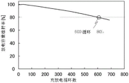
Fig. 19 is a graph showing the cycle characteristics of the secondary battery.
Modes for carrying out the invention
Embodiments of the present invention will be described in detail below with reference to the drawings. Note that the present invention is not limited to the following description, and a person of ordinary skill in the art can easily understand the fact that the modes and details thereof can be changed into various forms. The present invention should not be construed as being limited to the embodiments described below.
(embodiment mode 1)
The secondary battery of the present embodiment includes a positive electrode active material containing lithium, a transition metal, magnesium, oxygen, and fluorine, and an electrolyte solution containing lithium bis (oxalato) borate (LiBOB). The transition metal is at least one of cobalt, nickel and manganese. The positive electrode active material also contains aluminum. The electrolyte contains a lithium salt, and diethyl carbonate and ethylene carbonate dissolving the lithium salt. The lithium salt is lithium hexafluorophosphate. The negative active material is artificial graphite. Further, a mixture in which a conductive material is added to the positive electrode active material may be used, and Acetylene Black (AB), VGCF (registered trademark), or a graphene oxide compound may be used as the conductive material. The graphene oxide compound is particularly preferable because it has a small surface area and can suppress decomposition of the electrolytic solution.
Graphene compounds sometimes have excellent electrical characteristics of high conductivity and excellent physical characteristics of high flexibility and high mechanical strength. In addition, the graphene compound has a planar shape. The graphene compound can form an area contact having low contact resistance. Further, since the graphene compound has very high conductivity even when it is thin, a small amount of a conductive path can be efficiently formed in the active material layer. Therefore, the graphene compound is preferably used as a conductive auxiliary agent because the contact area between the active material and the conductive auxiliary agent can be increased. Further, the resistance may be reduced, which is preferable. Here, the graphene compound includes, for example, graphene, multilayer graphene, multi-graphene (multi graphene), graphene oxide, multilayer graphene oxide, multiple graphene oxide, reduced multilayer graphene oxide, reduced multiple graphene oxide, graphene quantum dots, and the like. The Reduced Graphene Oxide is also referred to as Reduced Graphene Oxide (hereinafter, RGO). Herein, RGO refers to, for example, a compound obtained by reducing Graphene Oxide (GO). When active material particles having a small particle diameter, for example, active material particles having a particle diameter of 1 μm or less are used, the specific surface area of the active material particles is large, and therefore, a large number of conductive paths for connecting the active material particles are required. In this case, it is particularly preferable that: a graphene compound capable of efficiently forming a conductive path even in a small amount is used. Further, in this specification and the like, graphene oxide refers to a graphene compound containing carbon and oxygen, having a sheet-like shape, including a functional group, particularly an epoxy group, a carboxyl group, or a hydroxyl group. Further, a plurality of graphene compounds are bonded to each other, whereby a graphene compound sheet in a net shape (hereinafter referred to as a graphene compound net or a graphene net) can be formed. When the graphene net covers the active materials, the graphene net may also be used as a binder to bond the active materials to each other. Therefore, the amount of the binder can be reduced or the binder can be not used, whereby the ratio of the active material in the volume of the electrode or the weight of the electrode can be increased. That is, the capacity of the secondary battery can be improved.
Fig. 1A and 1B show cycle characteristics of a secondary battery including a positive electrode active material containing lithium, cobalt, nickel, aluminum, oxygen, and fluorine, and an electrolyte containing 1 wt% of lithium bis (oxalato) borate. Fig. 1A shows the cycle characteristics under the conditions of 45 ℃ and 4.5V charging, and fig. 1B shows the cycle characteristics under the conditions of 60 ℃ and 4.5V charging. Fig. 19 also shows the result when the horizontal axis of the number of charging cycles is 800, and shows that the number of cycles corresponding to a maintenance rate of 80% is 600 cycles. Note that the portion of cycle number 300 in fig. 19 corresponds to fig. 1A.
In fig. 1A, the cycle conditions were CCCV charge (0.5C, 4.5V, end current 0.2C) and CC discharge (0.5C, 3.0V), and the cycle characteristics were evaluated at 45 ℃. In fig. 1B, the cycle conditions were CCCV charge (0.5C, 4.5V, and a termination current of 0.2C) and CC discharge (0.5C, 3V), and the cycle characteristics were evaluated at 60 ℃. Note that in fig. 1A, the initial discharge capacity of the secondary battery with the additive was 191.4 mAh/g.
Note that the electrolyte solution of these secondary batteries contains lithium hexafluorophosphate as a lithium salt, and diethyl carbonate and ethylene carbonate for dissolving the lithium salt, in addition to LiBOB. The ratio of ethylene carbonate to diethyl carbonate was 3: 7.
LiBOB as an additive is not easily dissolved in a solvent, and as shown in fig. 2, the discharge capacity decreases when the amount is large. In fig. 2, the vertical axis represents the maximum discharge capacity, and the graph shows the respective maximum discharge capacities of the secondary battery without the additive, the secondary battery with LiBOB of 1 wt%, the secondary battery with LiBOB of 1.5 wt%, and the secondary battery with LiBOB of 2 wt%. Note that fig. 2 shows the results of performing charging of 0.5C to 0.2C at 3V to 4.5V at 45 ℃ and performing discharging at 0.5C after the cutoff voltage is reached. Further, when the addition amount is too large, LiBOB may be precipitated at a low temperature, so the ratio of LiBOB in the electrolyte solution is preferably more than 0.1 wt% and less than 3 wt%.
The positive electrode active material is also characterized by containing lithium, cobalt, magnesium, aluminum, nickel, oxygen, and fluorine. By combining the positive electrode active material, the electrolyte, and the additive, a significant effect shown in fig. 1 appears.
The production of the positive electrode active material is described below with reference to the production flow shown in fig. 3.
< step S21>
First, a halogen source such as a fluorine source or a chlorine source, a magnesium source, a nickel source, and an aluminum source are prepared as materials of the mixture 901. Preferably, a lithium source is also prepared.
As the fluorine source, for example, lithium fluoride, magnesium fluoride, or the like can be used. Among these, lithium fluoride is preferably low in melting point of 848 ℃ and is easily melted in an annealing step described later. As the chlorine source, for example, lithium chloride, magnesium chloride, or the like can be used. Examples of the magnesium source include magnesium fluoride, magnesium oxide, magnesium hydroxide, and magnesium carbonate. As the lithium source, for example, lithium fluoride and lithium carbonate can be used. That is, lithium fluoride may be used as both a lithium source and a fluorine source. In addition, magnesium fluoride can be used as both a fluorine source and a magnesium source.
In the present embodiment, lithium fluoride LiF is prepared as a fluorine source and a lithium source, and magnesium fluoride MgF is prepared as a fluorine source and a magnesium source2(step S21 of FIG. 3).
When lithium fluoride LiF and magnesium fluoride MgF2The method comprises the following steps of (1) preparing LiF: MgF265: about 35 (molar ratio) is most effective in lowering the melting point. When the amount of lithium fluoride is large, lithium becomes too much and may cause deterioration of cycle characteristics. For this purpose, lithium fluoride LiF and magnesium fluoride MgF2The molar ratio of (c) is preferably LiF: MgF2X: 1(0. ltoreq. x. ltoreq.1.9), more preferably LiF: MgF2X: 1 (0.1. ltoreq. x. ltoreq.0.5), more preferably LiF: MgF2X: 1(x is about 0.33).
As the nickel source, for example, nickel hydroxide (Ni (OH))2). At this time, the nickel source is preferably micronized. For example, the nickel hydroxide is mixed and pulverized by a ball mill, a sand mill, or the like using acetone as a solvent to obtain micronized nickel hydroxide.
As the aluminum source, for example, aluminum hydroxide (Al (OH)3). The aluminium source is preferably micronized. For example, aluminum hydroxide is mixed and pulverized using acetone as a solvent by a ball mill, a sand mill, or the like, to obtain micronized aluminum hydroxide.
In addition, when the subsequent mixing and pulverizing steps are performed by a wet method, a solvent is prepared. As the solvent, ketones such as acetone, alcohols such as ethanol and isopropanol, diethyl ether, dioxane, acetonitrile, N-methyl-2-pyrrolidone (NMP), and the like can be used. It is preferable to use an aprotic solvent which does not readily react with lithium. In the present embodiment, acetone is used (see step S21 in fig. 3).
< step S22>
Next, the materials of the mixture 901 are mixed and pulverized (step S22 in fig. 3). Mixing may be performed using a dry method or a wet method, which can pulverize the material into smaller particles, and is therefore preferable. For example, a ball mill or a sand mill can be used for mixing. When a ball mill is used, for example, zirconium balls are preferably used as the medium. The mixing and pulverizing process is preferably performed sufficiently to micronize the mixture 901.
The mixing is preferably carried out by using a stirrer, a mixer, or a ball mill.
< step S23, step S24>
The mixed and pulverized material is recovered (step S23 in fig. 3) to obtain a mixture 901 (step S24 in fig. 3).
The mixture 901 preferably has a median particle diameter (D50) of 600nm or more and 20 μm or less, and more preferably 1 μm or more and 10 μm or less. By using the mixture 901 thus micronized, when the mixture is mixed with a composite oxide containing lithium, a transition metal, and oxygen in a later process, the mixture 901 is more likely to be uniformly attached to the surface of the particles of the composite oxide. When the mixture 901 is uniformly adhered to the surface of the particles of the composite oxide, the halogen and magnesium may be distributed over the entire surface layer portion of the composite oxide particles after heating, which is preferable. When a region containing no halogen and no magnesium is present in the surface layer portion, the above pseudospinel crystal structure is not easily formed in a charged state.
< step S25>
As step S25, a previously synthesized composite oxide containing lithium, a transition metal, and oxygen is used.
When a previously synthesized composite oxide containing lithium, a transition metal, and oxygen is used, it is preferable to use a composite oxide containing less impurities. In this specification and the like, lithium, cobalt, nickel, manganese, aluminum, and oxygen are used as main components of a composite oxide containing lithium, a transition metal, and oxygen, and a positive electrode active material, and elements other than the main components are used as impurities. For example, when analyzed by glow discharge mass spectrometry, the total impurity concentration is preferably 10,000ppm wt or less, more preferably 5000ppm wt or less. In particular, the total impurity concentration of a transition metal such as titanium and arsenic is preferably 3000ppm wt or less, more preferably 1500ppm wt or less.
For example, lithium cobaltate particles (trade name: CELLSEED C-10N) manufactured by Nippon CHEMICAL industry Co., Ltd., LTD) can be used as the lithium cobaltate synthesized in advance. The lithium cobaltate has a median particle diameter (D50) of about 12 [ mu ] m, and has a magnesium concentration and a fluorine concentration of 50ppm wt or less, a calcium concentration, an aluminum concentration and a silicon concentration of 100ppm wt or less, a nickel concentration of 150ppm wt or less, a sulfur concentration of 500ppm wt or less, an arsenic concentration of 1100ppm wt or less, and a concentration of an element other than lithium, cobalt and oxygen of 150ppm wt or less in impurity analysis by glow discharge mass spectrometry (GD-MS).
The composite oxide containing lithium, transition metal, and oxygen in step S25 preferably has a layered rock-salt crystal structure with few defects and deformations. For this reason, it is preferable to use a composite oxide containing less impurities. When a complex oxide containing lithium, a transition metal and oxygen contains a large amount of impurities, the crystal structure is likely to have a large number of defects or deformations.
< step S31>
Next, the mixture 901 and the composite oxide containing lithium, transition metal, and oxygen are mixed (step S31 of fig. 3). The number of transition metal atoms TM in the composite oxide containing lithium, transition metal and oxygen and the magnesium Mg in the mixture 902Mix1The ratio of the number of atoms of (c) is preferably TM: mg (magnesium)Mix11: y (0.005. ltoreq. y. ltoreq.0.05), more preferably TM: mg (magnesium)Mix11: y (0.007. ltoreq. y. ltoreq.0.04), more preferably TM: mg (Mg)Mix11: about 0.02.
The mixing of step S31 is preferably performed under milder conditions than the mixing of step S22 in order not to damage the particles of the composite oxide. For example, it is preferable to perform the mixing under the condition that the number of revolutions is smaller or the time is shorter than that of the mixing in step S22. Furthermore, the dry method is a milder condition compared to the wet method. The mixing may be performed by, for example, a ball mill, a sand mill, or the like. When a ball mill is used, for example, zirconium balls are preferably used as the medium.
The above mixed materials are recovered (step S32 of fig. 3) to obtain a mixture 903 (step S33 of fig. 3).
Next, the mixture 903 is heated (step S34 of fig. 3). This process is also sometimes referred to as annealing or firing. Annealing to form LiMO2. Thus, e.g. temperature, time, atmosphere orThe conditions for performing step S34, such as the weight of the mixture 903 subjected to annealing, are important. In addition, "annealing" in the present specification includes: in the case of heating the mixture 903; and heating a heating furnace in which at least the mixture 903 is disposed. In this specification, a heating furnace is an apparatus used for heat treatment (annealing) of a substance or a mixture, and includes a heater portion and an inner wall that can withstand an atmosphere containing a fluoride and at least 600 ℃. The heating furnace may be provided with a pump having a function of depressurizing and/or pressurizing the inside of the heating furnace. For example, the pressing may be performed during the annealing in S34.
The annealing temperature of S34 needs to be higher than the temperature at which the reaction of lithium cobaltate (S25) and fluoride progresses. Here, the temperature at which the reaction progresses may be a temperature at which interdiffusion of lithium cobaltate and an element included in the fluoride occurs. Thus, the temperature may also be below the melting temperature of these materials. For example, in oxides, from the melting temperature Tm0.757 times (Taman temperature T)d) Solid phase diffusion begins to occur. Thus, for example, it may be 500 ℃ or higher.
Note that the reaction is preferably performed at a temperature equal to or higher than the temperature at which at least a part of the mixture 903 is melted. Therefore, the annealing temperature is preferably equal to or higher than the eutectic point of the fluoride. The fluoride contains LiF and MgF2Then, as shown in FIG. 13 (FIG. 1471-A of non-patent document 1 is modified by citation), LiF and MgF2Since the eutectic point P of (2) is around 742 ℃ (T1), the annealing temperature of S34 is preferably 742 ℃ or higher.
The higher the annealing temperature of S34, the more easily the reaction proceeds, the shorter the annealing time, and the higher the productivity, and therefore, it is preferable.
In addition, the temperature at which annealing is performed needs to be LiCoO2The decomposition temperature (1130 ℃) of (A) is not higher than. Further, LiCoO2Has a decomposition temperature of 1130 ℃ but may generate a minute LiCoO at a temperature in the vicinity thereof2Decomposition of (3). Therefore, the annealing temperature is preferably 1130 ℃ or less, more preferably 1000 ℃ or less, still more preferably 950 ℃ or less, and still more preferably 900 ℃ or less.
Thus, the annealing temperature is preferably 500 ℃ or higher and 1130 ℃ or lower, more preferably 500 ℃ or higher and 1000 ℃ or lower, still more preferably 500 ℃ or higher and 950 ℃ or lower, and still more preferably 500 ℃ or higher and 900 ℃ or lower. Moreover, it is preferably 742 ℃ to 1130 ℃, more preferably 742 ℃ to 1000 ℃, still more preferably 742 ℃ to 950 ℃, yet still more preferably 742 ℃ to 900 ℃. Further, it is preferably 800 ℃ to 1130 ℃, more preferably 800 ℃ to 1000 ℃, further preferably 800 ℃ to 950 ℃, and most preferably 800 ℃ (T2) to 900 ℃ (T3) inclusive (range L). Further, it is preferably 830 ℃ to 1130 ℃, more preferably 830 ℃ to 1000 ℃, still more preferably 830 ℃ to 950 ℃, and yet more preferably 830 ℃ to 900 ℃.
More specifically, by using LiF as the fluoride and performing annealing at S34 with a lid, a positive electrode active material having good cycle characteristics and the like can be produced. In addition, it can be considered that: use of LiF and MgF as fluorides2When it is reacted with LiCoO2To form LiMO2。
In addition, it is considered that LiF as a fluoride is used as the flux in the present embodiment. Thus, it can be estimated that: the volume inside the furnace is larger than the volume of the vessel and LiF is lighter than oxygen, so when LiF volatilizes and LiF in the mixture 903 decreases, LiMO2Is suppressed. Therefore, heating while suppressing volatilization of LiF is required. In addition, when LiF is not used, Li on the surface of lithium cobaltate reacts with F to generate LiF, and LiF may volatilize. Thus, even if fluoride having a melting point higher than LiF is used, it is similarly necessary to suppress volatilization.
Thus, volatilization of LiF in the mixture 903 is suppressed by heating the mixture 903 under an atmosphere containing LiF, that is, heating the mixture 903 in a state where the partial pressure of LiF in the heating furnace is high. By using a fluoride (LiF or MgF) forming a eutectic mixture and annealing with a lid, the annealing temperature can be lowered to LiCoO2Is not more than 1130 ℃ and, more specifically, is not less than 742 ℃ and not more than 1000 ℃, whereby L is efficiently developediMO2And (4) generating. Therefore, a positive electrode active material having good characteristics can be produced, and the annealing time can be shortened.
The annealing of step S34 described above is preferably performed at an appropriate temperature and time. The appropriate temperature and time are different depending on conditions such as the size and composition of the lithium cobaltate (S25) particles. In the case where the particles are small, annealing at a lower temperature or in a shorter time is sometimes preferable than when the particles are large. The method includes a step of removing the lid after the annealing in S34.
For example, when the median diameter (D50) of the particles of the lithium cobaltate (S25) is about 12 μm, the annealing time is, for example, preferably 3 hours or more, and more preferably 10 hours or more.
On the other hand, when the median diameter (D50) of the particles of the lithium cobaltate (S25) is about 5 μm, the annealing time is, for example, preferably 1 hour or more and 10 hours or less, and more preferably about 2 hours.
The temperature reduction time after annealing is preferably 10 hours or more and 50 hours or less, for example.
The annealed material is recovered (step S35 in fig. 3). Also, the particles are preferably screened. Through the above steps, the positive electrode active material 200A according to one embodiment of the present invention can be produced (step S36 in fig. 3).
The positive electrode active material is not limited to the above-described structure, and even if a positive electrode active material that does not use nickel and aluminum is used, a significant effect can be obtained by combining the positive electrode active material, the electrolyte solution, and the additive.
Another example of the production of the positive electrode active material not using nickel and aluminum is shown below with reference to the production flow shown in fig. 4.
As shown in step S11 of fig. 4, first, as a material of the mixture 902, lithium fluoride serving as a fluorine source and magnesium fluoride serving as a magnesium source are prepared. Lithium fluoride is preferably low in melting point of 848 ℃ because it is easily melted in the annealing step described later. Lithium fluoride can be used as both a lithium source and a fluorine source. Further, magnesium fluoride may be used as both a fluorine source and a magnesium source.
In FIG. 4, lithium fluoride LiF was prepared as a fluorine source and a lithium source, and lithium fluoride LiF was prepared as a fluorine source and a magnesium sourcePreparing magnesium fluoride MgF2(step S11 of FIG. 4). Lithium fluoride LiF and magnesium fluoride MgF2The molar ratio of (c) is preferably LiF: MgF2X: 1(0. ltoreq. x. ltoreq.1.9), more preferably LiF: MgF2X: 1 (0.1. ltoreq. x. ltoreq.0.5), more preferably LiF: MgF2X: 1(x is about 0.33).
In addition, when the subsequent mixing and pulverizing steps are performed by a wet method, a solvent is prepared. As the solvent, ketones such as acetone, alcohols such as ethanol and isopropanol, diethyl ether, dioxane, acetonitrile, N-methyl-2-pyrrolidone (NMP), and the like can be used. It is preferable to use an aprotic solvent which does not readily react with lithium. In the present embodiment, acetone is used (see step S11 in fig. 4).
Next, the materials of the mixture 902 are mixed and pulverized (step S12 of fig. 4). Mixing may be performed using a dry method or a wet method, which may pulverize the material to be smaller, and is therefore preferable. For example, a ball mill or a sand mill can be used for mixing. When a ball mill is used, for example, zirconium balls are preferably used as the medium. The mixing and pulverizing process is preferably performed sufficiently to micronize the mixture 902.
The mixed and pulverized material is recovered (step S13 in fig. 4) to obtain a mixture 902 (step S14 in fig. 4).
The mixture 902 is preferably one in which D50 is 600nm or more and 20 μm or less, and more preferably 1 μm or more and 10 μm or less, for example. By using the mixture 902 thus micronized, when the mixture is mixed with a composite oxide containing lithium, a transition metal, and oxygen in a later step, the mixture 902 is more likely to be uniformly attached to the surface of the particles of the composite oxide. When the mixture 902 is uniformly adhered to the surface of the composite oxide particle, the halogen and magnesium are preferably distributed over the entire surface layer portion of the composite oxide particle after heating. When a region containing no halogen and no magnesium is present in the surface layer portion, the above pseudospinel crystal structure is not easily formed in a charged state.
Next, a lithium source is prepared as shown in step S25. As step S25, a previously synthesized composite oxide containing lithium, a transition metal, and oxygen is used.
For example, lithium cobaltate particles (trade name: CELLSEED C-10N) manufactured by Nippon CHEMICAL industry Co., Ltd. can be used as the lithium cobaltate synthesized in advance. The lithium cobaltate has a median particle diameter (D50) of about 12 [ mu ] m, and has a magnesium concentration and a fluorine concentration of 50ppm wt or less, a calcium concentration, an aluminum concentration and a silicon concentration of 100ppm wt or less, a nickel concentration of 150ppm wt or less, a sulfur concentration of 500ppm wt or less, an arsenic concentration of 1100ppm wt or less, and a concentration of an element other than lithium, cobalt and oxygen of 150ppm wt or less in impurity analysis by glow discharge mass spectrometry (GD-MS).
The composite oxide containing lithium, transition metal, and oxygen in step S25 preferably has a layered rock-salt crystal structure with few defects and deformations. For this reason, it is preferable to use a composite oxide containing less impurities. When a complex oxide containing lithium, a transition metal, and oxygen contains a large amount of impurities, the crystal structure is likely to have a large number of defects or deformations.
Next, the mixture 902 and the composite oxide containing lithium, transition metal, and oxygen are mixed (step S31 of fig. 4). The number of transition metal atoms TM in the composite oxide containing lithium, transition metal and oxygen and the magnesium Mg in the mixture 902Mix1The ratio of the number of atoms of (c) is preferably TM: mg (magnesium)Mix11: y (0.005. ltoreq. y. ltoreq.0.05), more preferably TM: mg (magnesium)Mix11: y (0.007. ltoreq. y. ltoreq.0.04), more preferably TM: mg (magnesium)Mix11: about 0.02.
The mixing of step S31 is preferably performed under milder conditions than the mixing of step S12 in order not to damage the particles of the composite oxide. For example, it is preferable to perform the mixing under the condition of a smaller number of revolutions or a shorter time than the mixing in step S12. Furthermore, the dry method is a milder condition compared to the wet method. For example, a ball mill or a sand mill can be used for mixing. When a ball mill is used, for example, zirconium balls are preferably used as the medium.
The above mixed materials are recovered (step S32 of fig. 4) to obtain a mixture B (step S33 of fig. 4).
Next, the mixture B is heated (step S34 of fig. 4).
The annealing is preferably performed at an appropriate temperature and time. The appropriate temperature and time vary depending on the conditions such as the size and composition of the particles of the composite oxide containing lithium, transition metal, and oxygen in step S25. In the case where the particles are small, annealing at a lower temperature or in a shorter time is sometimes preferable than when the particles are large.
For example, when the median diameter (D50) of the particles in step S25 is about 12 μm, the annealing temperature is, for example, preferably 600 ℃ or higher and 950 ℃ or lower. The annealing time is, for example, preferably 3 hours or more, more preferably 10 hours or more, and further preferably 60 hours or more.
When the median diameter (D50) of the particles of step S25 is about 5 μm, the annealing temperature is, for example, preferably 600 ℃ to 950 ℃. The annealing time is, for example, preferably 1 hour or more and 10 hours or less, and more preferably about 2 hours.
The temperature reduction time after annealing is preferably 10 hours or more and 50 hours or less, for example.
It is considered that when the mixture B is annealed, the low-melting-point material (for example, lithium fluoride, melting point 848 ℃) in the mixture B melts first and is distributed in the surface layer portion of the composite oxide particles. Next, it is presumed that the melting point of the other material is lowered by the presence of the molten material, and the other material is melted. For example, it is considered that magnesium fluoride (melting point 1263 ℃) melts and is distributed in the surface layer portion of the composite oxide particle.
The elements contained in the mixture B diffuse more rapidly in the surface layer portion and the vicinity of the grain boundary than in the interior of the composite oxide particles. Therefore, the concentrations of magnesium and halogen in the surface layer portion and the vicinity of the grain boundary are higher than those in the composite oxide particle. As described later, the higher the magnesium concentration in the surface layer portion and the vicinity of the grain boundary, the more effectively the change in the crystal structure can be suppressed.
The annealed material is recovered (step S35 in fig. 4) to obtain a positive electrode active material 200B (step S36 in fig. 4).
When an electrolyte solution to which LiBOB is added is used as a secondary battery using the positive electrode active material 200B obtained in the above-described procedure, good results can be obtained as cycle characteristics at 45 ℃.
(embodiment mode 2)
An example of a method for manufacturing a laminated secondary battery is described with reference to fig. 5B and 5C.
First, the negative electrode 506, the separator 507, and the positive electrode 503 are stacked.
Fig. 5A shows an external view of the positive electrode 503 and the negative electrode 506. The positive electrode 503 includes a positive electrode current collector 501, and a positive electrode active material layer 502 is formed on the surface of the positive electrode current collector 501. The anode active material: acetylene Black (AB): polyvinylidene fluoride (PVDF) ═ 95: 3: 2 (weight ratio), AB and PVDF, and the positive electrode active material was applied to the positive electrode current collector 501, and the positive electrode active material layer 502 was formed by pressing at 120 ℃ at a line pressure of 120 kN/m. AB is used as a conductive material (also referred to as a conductive aid). The mixing method comprises the following steps: first, an active material, AB, and tetra-form polyvinylidene fluoride (PVDF) were mixed and kneaded until uniform, and then the remaining (hexa-form) PVDF was added and NMP was further mixed to adjust the viscosity, thereby producing a slurry. After coating, drying was carried out at 80 ℃ for 30 minutes using a circulating drying oven.
The positive electrode 503 has a region (hereinafter referred to as tab region) where a part of the positive electrode current collector 501 is exposed. The negative electrode 506 has a negative electrode current collector 504, and a negative electrode active material layer 505 is formed on the surface of the negative electrode current collector 504. The negative electrode 506 has a tab region, which is a region where a part of the negative electrode current collector 504 is exposed. The areas and shapes of the tab regions of the positive and negative electrodes are not limited to the example shown in fig. 5A.
Fig. 5B shows the stacked anode 506, separator 507, and cathode 503. Here, an example using 5 sets of negative electrodes and 4 sets of positive electrodes is shown. Next, the tab regions of the positive electrodes 503 are joined to each other, and the positive electrode lead electrode 510 is joined to the tab region of the outermost positive electrode. For example, ultrasonic welding or the like can be used for bonding. Similarly, the tab regions of the negative electrodes 506 are joined to each other, and the negative lead electrode 511 is joined to the tab region of the outermost negative electrode.
Next, the negative electrode 506, the separator 507, and the positive electrode 503 are disposed on the exterior package 509.
Next, as shown in fig. 5C, the outer package 509 is folded along the portion indicated by the broken line. Then, the outer peripheral portion of the outer package 509 is joined. For example, thermal compression bonding or the like can be used for bonding. At this time, a region (hereinafter referred to as an inlet) which is not bonded to a part (or one side) of the outer package 509 is provided for later injection of the electrolyte 508.
Next, the electrolytic solution 508 is introduced into the outer package 509 from an inlet provided in the outer package 509. The electrolytic solution 508 is preferably introduced under a reduced pressure atmosphere or an inert atmosphere. In the present embodiment, 1mol/l LiPF is used as the lithium salt6As solvent, EC: DEC ═ 3: EC and DEC were used in the proportion of 7 (volume ratio), LiBOB was used as an additive in an amount of 1 wt%, and the total amount introduced from the inlet was 600. mu.L. Finally, the inlets are joined. In this manner, the secondary battery 500 of the laminate type secondary battery can be manufactured.
By using the positive electrode active material particles and LiBOB described in the above embodiment mode for the positive electrode 503, a secondary battery 500 with less deterioration and high safety can be realized.
Next, an aging process performed after the production of the secondary battery will be described. The aging process is preferably performed after the secondary battery is manufactured. An example of the aging process conditions will be described below. First, charging is performed at a rate of 0.001C or more and 0.2C or less. The temperature may be set to room temperature or higher and 60 ℃ or lower. Here, when the reaction potential of the positive electrode or the negative electrode exceeds the potential window of the electrolyte solution 508, the electrolyte solution may be decomposed by charge and discharge of the secondary battery. If decomposition of the electrolyte causes generation of gas, the battery is filled with the gas, and thus the electrolyte cannot contact the electrode surface in some region. That is, the effective reaction area of the electrode is reduced, and the effective resistance is increased.
In addition, if the resistance is too high, the negative electrode potential decreases, and lithium is intercalated into graphite and lithium is precipitated on the graphite surface. This lithium deposition sometimes leads to a decrease in capacity. For example, if a film or the like is grown on the surface after lithium deposition, lithium deposited on the surface cannot be eluted again, and lithium that does not contribute to capacity is increased. When the deposited lithium is physically damaged and cannot be electrically connected to the electrode, lithium that does not contribute to the capacity is similarly generated. Therefore, it is preferable to perform degassing before the potential of the negative electrode reaches the lithium potential due to the increase in the charging voltage.
After the degassing is performed, the charged state may be maintained at a temperature higher than room temperature, preferably 30 ℃ or higher and 60 ℃ or lower, and more preferably 35 ℃ or higher and 50 ℃ or lower, for example, 1 hour or higher and 100 hours or lower. During the initial charging, the electrolyte decomposed on the surface forms a film on the graphite surface. Therefore, for example, by maintaining the charged state at a temperature higher than room temperature after performing degassing, it is possible to densify the formed coating film.
Further, the remaining electrolyte is sometimes removed after degassing is performed. However, since the amount of the electrolyte is very small, it is considered that the change in the weight of the battery or the like is hardly affected.
An example of a method for manufacturing a laminate-type secondary battery will be described with reference to fig. 6A and 6B.
Fig. 6A shows an example of an external view of a laminate-type secondary battery 500. Fig. 6B shows another example of an external view of the laminate type secondary battery 500.
Fig. 6A and 6B include: a positive electrode 503; a negative electrode 506; an insulator 507; an outer package body 509; a positive electrode lead electrode 510; and a negative lead electrode 511.
The laminate-type secondary battery 500 includes a plurality of positive electrodes 503 in a stripe shape, separators 507, and a plurality of negative electrodes 506 in a stripe shape.
In the example of lamination shown in fig. 5, a roll may be used. In this case, the negative electrode 506 and the positive electrode 503 are stacked on each other with the separator 507 interposed therebetween to form a laminated sheet, and the wound body is wound around the laminated sheet.
Fig. 7A shows a positive electrode including a positive electrode current collector 701 and a positive electrode active material layer 702, which has an L-shape. The positive electrode has a region where a part of the positive electrode current collector 701 is exposed (hereinafter referred to as a tab region). Fig. 7B shows a negative electrode including a negative electrode current collector 704 and a negative electrode active material layer 705, which has an L-shaped shape. The negative electrode has a region where a part of the negative electrode current collector 704 is exposed, i.e., a tab region.
Fig. 7C is a perspective view in which four positive electrodes 703 and four negative electrodes 706 are stacked. Note that in fig. 7C, the separator provided between the cathode 703 and the anode 706 is indicated by a broken line for the sake of simplicity.
The laminate-type secondary battery shown in fig. 8A includes: an L-shaped positive electrode 703 including a positive electrode current collector 701 and a positive electrode active material layer 702; an L-shaped negative electrode 706 including a negative electrode current collector 704 and a negative electrode active material layer 705; an isolator 707; an electrolyte 708; and an outer package 709. A separator 707 is provided between the positive electrode 703 and the negative electrode 706 provided in the outer package 709. The outer package 709 is filled with an electrolyte 708.
In the laminate type secondary battery shown in fig. 8A, the positive electrode current collector 701 and the negative electrode current collector 704 also serve as terminals that are electrically contacted with the outside. Therefore, a part of the positive electrode current collector 701 and the negative electrode current collector 704 may be exposed to the outside of the outer package 709. The lead electrode may be exposed to the outside of the outer package 709 by ultrasonically welding the lead electrode to the positive electrode current collector 701 or the negative electrode current collector 704 using the lead electrode without exposing the positive electrode current collector 701 or the negative electrode current collector 704 to the outside of the outer package 709.
In the laminate type secondary battery, as the outer package 709, for example, a laminate film having a three-layer structure as follows can be used: a highly flexible metal thin film of aluminum, stainless steel, copper, nickel or the like is provided on a film made of a material such as polyethylene, polypropylene, polycarbonate, ionomer, polyamide or the like, and an insulating synthetic resin thin film of polyamide resin, polyester resin or the like is provided on the metal thin film as an outer surface of the outer package.
Fig. 8B shows an example of a cross-sectional structure of the laminate type secondary battery. In fig. 8A, it is omitted for the sake of simplicity, but in reality the cell includes a plurality of electrode layers.
In fig. 8B, for example, 16 electrode layers are included. Fig. 8B shows a structure of a total of 16 layers of the negative electrode current collector 704 having 8 layers and the positive electrode current collector 701 having 8 layers. Fig. 8B shows a cross section of the extraction portion of the positive electrode cut along the chain line of fig. 8A, and the 8-layer negative electrode current collector 704 is subjected to ultrasonic welding. Of course, the number of electrode layers is not limited to 16, and may be more or less. When the number of electrode layers is large, a secondary battery having a larger capacity can be manufactured. In addition, when the number of electrode layers is small, the thickness can be reduced.
Further, an example of the cylindrical secondary battery will be described with reference to fig. 9A to 9D. As shown in fig. 9A, a cylindrical secondary battery 600 has a positive electrode cover (battery cover) 601 on the top surface and a battery can (outer can) 602 on the side surface and the bottom surface. The positive electrode cover is insulated from the battery can (outer can) 602 by a gasket (insulating gasket) 610.
Fig. 9B is a view schematically showing a cross section of the cylindrical secondary battery. Inside the hollow cylindrical battery can 602, a battery element in which a strip-shaped positive electrode 604 and a strip-shaped negative electrode 606 are wound with a separator 605 interposed therebetween is provided. Although not shown, the battery element is wound around a center pin. One end of the battery can 602 is closed and the other end is open. As the battery can 602, a metal such as nickel, aluminum, or titanium, an alloy thereof, or an alloy thereof with other metals (e.g., stainless steel) having corrosion resistance to an electrolyte can be used. In addition, in order to prevent corrosion by the electrolytic solution, it is preferable to cover nickel, aluminum, or the like. Inside the battery can 602, a battery element in which a positive electrode, a negative electrode, and a separator are wound is sandwiched between a pair of insulating plates 608 and 609 that face each other. A nonaqueous electrolytic solution (not shown) is injected into the battery case 602 provided with the battery element. As the nonaqueous electrolytic solution, the same electrolytic solution as that of the coin-type secondary battery can be used.
Since the positive electrode and the negative electrode for the cylindrical secondary battery are wound, the active material is preferably formed on both surfaces of the current collector. The positive electrode 604 is connected to a positive terminal (positive current collecting wire) 603, and the negative electrode 606 is connected to a negative terminal (negative current collecting wire) 607. A metal material such as aluminum can be used for both the positive electrode terminal 603 and the negative electrode terminal 607. The positive terminal 603 is resistance-welded to the safety valve mechanism 612, while the negative terminal 607 is electrically connectedSolder resist is attached to the bottom of the battery can 602. The safety valve mechanism 612 and the Positive electrode cap 601 are electrically connected by a PTC element (Positive Temperature Coefficient) 611. When the internal pressure of the battery rises to exceed a predetermined threshold value, the safety valve mechanism 612 cuts off the electrical connection between the positive electrode cover 601 and the positive electrode 604. In addition, the PTC element 611 is a heat sensitive resistance element whose resistance increases at the time of temperature rise, and limits the amount of current by the increase of resistance to prevent abnormal heat generation. As the PTC element, barium titanate (BaTiO) can be used3) Quasi-semiconductor ceramics, and the like.
As shown in fig. 9C, a plurality of secondary batteries 600 may be sandwiched between a conductive plate 613 and a conductive plate 614 to form a module 615. The plurality of secondary batteries 600 may be connected in parallel, connected in series, or connected in parallel and then connected in series. By constituting the module 615 including a plurality of secondary batteries 600, it is possible to extract a large electric power.
Fig. 9D is a top view of module 615. For clarity, the conductive plate 613 is shown in dashed lines. As shown in fig. 9D, the module 615 may include a wire 616 that electrically connects the plurality of secondary batteries 600. A conductive plate may be disposed on the conductive line 616 in such a manner as to overlap the conductive line 616. Further, temperature control device 617 may be provided between the plurality of secondary batteries 600. When secondary battery 600 is overheated, it may be cooled by temperature control device 617, and when secondary battery 600 is overcooled, it may be heated by temperature control device 617. The performance of the module 615 is thus not easily affected by the outside air temperature.
When the positive electrode active material produced by the production method described in the above embodiment is used for the positive electrode 604, the cylindrical secondary battery 600 with less deterioration and high safety can be realized.
(embodiment mode 3)
[ Structure of Positive electrode active Material ]
Lithium cobaltate (LiCoO)2) And the like have a layered rock salt type crystal structure, have a high discharge capacity, and are considered to be excellent positive electrode active materials for secondary batteries. The material having a layered rock salt crystal structure may be, for example, LiMO2The compound oxide shown. As an example of element M, canOne or more selected from the group consisting of Co, Ni and Mn. Further, as an example of the element M, one or more selected from Al and Mg may be mentioned in addition to one or more selected from Co, Ni and Mn.
The magnitude of the ginger-taylor effect of the transition metal oxide is considered to be changed depending on the number of electrons of the d orbital of the transition metal.
Nickel-containing compounds are sometimes prone to skewing due to the ginger-taylor effect. Thus, in LiNiO2When charging and discharging are performed at a high voltage, a crystal structure may collapse due to distortion. LiCoO2The ginger-taylor effect of (b) is less adversely affected, and the resistance to charge and discharge at high voltage may be more excellent, and therefore, is preferable.
The positive electrode active material will be described below with reference to fig. 10 and 11. Fig. 10 and 11 illustrate a case where cobalt is used as a transition metal contained in the positive electrode active material.
< conventional Positive electrode active Material >
The positive electrode active material shown in fig. 11 is lithium cobaltate (LiCoO) to which no halogen or magnesium is added2). The crystal structure of lithium cobaltate shown in fig. 11 changes depending on the charging depth.
As shown in fig. 11, lithium cobaltate whose charge depth is 0 (discharge state) includes a region having a crystal structure of space group R-3m, lithium occupies Octahedral (Octahedral) positions, and includes three coos in a unit cell2And (3) a layer. Thus, this crystal structure is sometimes referred to as an O3 type crystal structure. Note that CoO2The layer is a structure in which an octahedral structure formed by cobalt and six coordinated oxygens maintains a state in which ridges are shared on one plane.
When the depth of charge is 1, has a crystal structure of space group P-3m1, and the unit cell includes a CoO2And (3) a layer. Thus, this crystal structure is sometimes referred to as an O1 type crystal structure.
When the charge depth is about 0.8, lithium cobaltate has a crystal structure of space group R-3 m. The structure can also be said to be a CoO such as P-3m1(O1)2LiCoO with a structure similar to that of R-3m (O3)2The structures are alternately stacked. Thus, there areThis crystal structure is referred to as H1-3 type crystal structure. In fact, the number of cobalt atoms in the unit cell of the H1-3 type crystal structure is 2 times that of the other structures. However, in this specification such as fig. 11, the c-axis in the H1-3 type crystal structure is represented as 1/2 of a unit cell for easy comparison with other structures.
As an example of the H1-3 type crystal structure, the coordinates of cobalt and oxygen in the unit cell can be represented by Co (0, 0, 0.42150. + -. 0.00016), O1(0,0,0.27671±0.00045)、O2(0, 0, 0.11535. + -. 0.00045). O is1And O2Are all oxygen atoms. As such, the H1-3 type crystal structure is represented by a unit cell using one cobalt and two oxygen. On the other hand, as described below, it is preferable to express the O3' type crystal structure in one embodiment of the present invention in a unit cell using one cobalt and one oxygen. This indicates that the O3 'type crystal structure differs from the H1-3 type crystal structure in the symmetry of cobalt and oxygen, and that the O3' type crystal structure changes less from the O3 structure than the H1-3 type crystal structure. For example, any unit cell may be selected so as to more suitably express the crystal structure of the positive electrode active material under the condition that the GOF (good of fit) value in the ritnwalder analysis of the XRD pattern is as small as possible.
When high-voltage charging with a charging voltage of 4.6V or more with respect to the redox potential of lithium metal or deep charging and discharging with a charging depth of 0.8 or more are repeated, the crystal structure of lithium cobaltate is repeatedly changed (i.e., nonequilibrium phase transition) between the H1-3 type crystal structure and the crystal structure of R-3m (O3) in a discharged state.
However, CoO of the above two crystal structures2The deviation of the layer is large. As shown by the dotted line and arrow in FIG. 11, in the H1-3 crystal structure, CoO2The layers deviate significantly from R-3m (O3). Such dynamic structural changes can adversely affect the stability of the crystal structure.
Also, the volume difference is large. The difference in volume between the H1-3 type crystal structure and the O3 type crystal structure in a discharged state is 3.0% or more per the same number of cobalt atoms.
In addition to the above, the H1-3 type crystal structure has a CoO like P-3m1(O1)2The possibility of structural instability of the layer continuity is high.
Thus, when high-voltage charge and discharge are repeated, the crystal structure of lithium cobaltate collapses. And collapse of the crystal structure causes deterioration of cycle characteristics. This is because the sites where lithium can stably exist are reduced due to collapse of the crystal structure, and insertion and desorption of lithium become difficult.
< Positive electrode active Material according to one embodiment of the present invention >
The positive electrode active material 904 manufactured in one embodiment of the present invention can reduce CoO even when charge and discharge are repeated at a high voltage2Deviation of the layers. Furthermore, volume changes can be reduced. Therefore, the compound can realize excellent cycle characteristics. In addition, the compound may have a stable crystal structure in a high-voltage charged state. Thus, the compound is less likely to cause short-circuiting even when the charged state of the compound is maintained at a high voltage. In this case, safety is further improved, which is preferable.
The positive electrode active material according to one embodiment of the present invention has a small change in crystal structure between a fully discharged state and a charged state at a high voltage, and a small volume difference between the two states when compared with each other for the same number of transition metal atoms.
Fig. 10 shows a crystal structure of a positive electrode active material 904 according to an embodiment of the present invention before and after charge and discharge. The positive electrode active material 904 is a composite oxide containing lithium, cobalt as a transition metal, and oxygen. Preferably, magnesium is contained as an additive element in addition to the above. Further, it is preferable that the additive element contains a halogen such as fluorine or chlorine.
The crystal structure of the charge depth 0 (discharge state) of fig. 10 is the same R-3m (O3) as fig. 11. However, the positive electrode active material 904 has a crystal structure different from the H1-3 type crystal structure when it has a sufficiently charged depth of charge. The structure is a space group R-3m, not a spinel crystal structure, but ions of cobalt, magnesium and the like occupy an oxygen 6 coordination position, and the arrangement of cations has symmetry similar to that of the spinel structure. In addition, the first and second substrates are,in this structure, CoO2The symmetry of the layers is the same as the O3 type. Therefore, this structure is referred to as an O3' type crystal structure or a pseudospinel type crystal structure in this specification and the like. Therefore, the O3' type crystal structure can also be referred to as a pseudospinel type crystal structure. In addition, in order to explain the symmetry of cobalt atoms and the symmetry of oxygen atoms, lithium is not shown in the diagram of the O3' type crystal structure shown in fig. 10, but CoO is actually used2Lithium is present between the layers at 20 atomic% or less, for example, with respect to cobalt. Further, of the O3 type crystal structure and O3' type crystal structure, CoO is preferable2A small amount of magnesium is present between the layers, i.e. at the lithium sites. In addition, a small amount of halogen such as fluorine is preferably present at the oxygen site in an irregular manner.
Further, in the O3' type crystal structure, a light element such as lithium sometimes occupies an oxygen 4 coordination site, and in this case, the arrangement of ions also has symmetry similar to that of the spinel type.
The O3' type crystal structure may have a structure in which Li is irregularly contained in the interlayer, but may have a structure in which Li is mixed with CdCl2Crystal structure of the crystal type is similar to that of the crystal type. The and CdCl2The crystal structure of the type analogous was similar to that of lithium nickelate charged to a depth of charge of 0.94 (Li)0.06NiO2) But a pure lithium cobaltate or a layered rock salt type positive electrode active material containing a large amount of cobalt generally does not have such a crystal structure.
In the positive electrode active material 904 according to one embodiment of the present invention, the change in the crystal structure when a large amount of lithium is desorbed by high-voltage charging is further suppressed as compared with a conventional positive electrode active material. For example, as shown by the dotted line in FIG. 10, there is almost no CoO in the above crystal structure2Deviation of the layers.
More specifically, the positive electrode active material 904 according to one embodiment of the present invention has structural stability even when the charging voltage is high. For example, although a conventional positive electrode active material has an H1-3 type crystal structure at a charging voltage of about 4.6V based on the potential of lithium metal, the positive electrode active material 904 according to one embodiment of the present invention can maintain the crystal structure of R-3m (O3) even at the charging voltage of about 4.6V. The positive electrode active material 904 according to one embodiment of the present invention may have an O3' type crystal structure even at a higher charging voltage, for example, a voltage of about 4.65V to 4.7V with respect to the potential of lithium metal. When the charging voltage is increased to a voltage higher than 4.7V, H1-3 type crystals are not observed in the positive electrode active material 904 according to one embodiment of the present invention. Further, at a lower charging voltage (for example, a charging voltage of 4.5V or more and less than 4.6V with respect to the potential of lithium metal), the positive electrode active material 904 according to one embodiment of the present invention may have an O3' type crystal structure.
For example, in the case of using graphite as a negative electrode active material of a secondary battery, the voltage of the secondary battery is lower than that of the above case by the potential of graphite. The potential of graphite is about 0.05V to 0.2V with respect to the potential of lithium metal. Therefore, the positive electrode active material 904 according to one embodiment of the present invention can maintain the crystal structure of R-3m (O3) even at a voltage of 4.3V or more and 4.5V or less of a secondary battery using graphite as a negative electrode active material, and can have an O3' type crystal structure even at a voltage exceeding 4.5V and 4.6V or less of a secondary battery, for example, in a region where the charging voltage is further increased. Further, at a lower charging voltage, for example, a voltage of 4.2V or more and less than 4.3V of the secondary battery, the positive electrode active material 904 according to one embodiment of the present invention may have an O3' type crystal structure.
Thus, the crystal structure of the positive electrode active material 904 according to one embodiment of the present invention is not easily collapsed even when charge and discharge are repeated at a high voltage.
In the positive electrode active material 904, the volume difference between the O3 type crystal structure having a depth of charge of 0 and the O3' type crystal structure having a depth of charge of 0.8 is 2.5% or less, specifically 2.2% or less.
The coordinates of cobalt and oxygen in the unit cell of O3' type crystal structure can be represented by the ranges of Co (0, 0, 0.5), O (0, 0, x), 0.20. ltoreq. x.ltoreq.0.25, respectively.
In CoO2CoO inhibition by an additive element such as magnesium present in small amounts irregularly between layers (i.e., in the lithium position)2Bias of layerThe effect of the detachment. Thereby when in CoO2The presence of magnesium between the layers readily gives a crystal structure of the O3' type. Therefore, it is preferable that magnesium is distributed throughout the particles of the positive electrode active material 904 according to one embodiment of the present invention. In order to distribute magnesium throughout the entire particle, it is preferable to perform heat treatment in the production process of the positive electrode active material 904 according to one embodiment of the present invention.
However, when the temperature of the heat treatment is too high, cation mixing (cation mixing) occurs, and the possibility that an additive element such as magnesium enters the cobalt site increases. Magnesium present at the cobalt site does not have the effect of retaining R-3m upon high voltage charging. Further, when the heat treatment temperature is too high, cobalt may be reduced to have an adverse effect such as divalent state and evaporation of lithium.
Therefore, it is preferable to add a halogen compound such as a fluorine compound to the lithium cobaltate before performing a heating treatment for distributing magnesium throughout the entire particle. The melting point of lithium cobaltate was lowered by adding the halogen compound. By lowering the melting point, magnesium can be easily distributed over the entire particle at a temperature at which cation mixing is less likely to occur. When a fluorine compound is also present, it is expected to improve corrosion resistance against hydrofluoric acid generated by decomposition of the electrolyte.
Note that when the magnesium concentration is higher than a desired value, the effect of stabilizing the crystal structure may be reduced. This is because magnesium enters not only lithium sites but also cobalt sites. The atomic number of magnesium contained in the positive electrode active material according to one embodiment of the present invention is preferably 0.001 times or more and 0.1 times or less, more preferably more than 0.01 times and less than 0.04 times, and still more preferably about 0.02 times the atomic number of the transition metal. The concentration of magnesium shown here may be a value obtained by elemental analysis of the entire particles of the positive electrode active material using ICP-MS or the like, or a value obtained from mixing of raw materials in the production process of the positive electrode active material, for example.
For example, it is preferable to add one or more metals selected from nickel, aluminum, manganese, titanium, vanadium, and chromium as metals (additive elements) other than cobalt to lithium cobaltate, and it is particularly preferable to add one or more metals selected from nickel and aluminum. Manganese, titanium, vanadium and chromium are sometimes stable to be tetravalent and sometimes contribute greatly to the structural stabilization. The positive electrode active material according to one embodiment of the present invention can have a more stable crystal structure in a charged state at a high voltage, for example, by adding an additive element. Here, in the positive electrode active material according to another embodiment of the present invention, it is preferable that the additive element is added at a concentration that does not significantly change the crystallinity of the lithium cobaltate. For example, the addition amount is preferably such that the ginger-taylor effect or the like described above is not caused.
As shown in fig. 10, the transition metal such as nickel or manganese and aluminum are preferably present at the cobalt site, but a part thereof may be present at the lithium site. Furthermore, magnesium is preferably present at the lithium site. A part of the oxygen may also be substituted by fluorine.
The increase in the magnesium concentration of the positive electrode active material according to one embodiment of the present invention may reduce the capacity of the positive electrode active material. This is mainly probably because, for example, magnesium enters lithium sites so that the amount of lithium contributing to charge and discharge is reduced. In addition, excess magnesium may produce a magnesium compound that does not contribute to charge and discharge. The positive electrode active material according to one embodiment of the present invention may contain nickel as an additive element in addition to magnesium, thereby increasing the capacity per unit weight and volume. In addition, the positive electrode active material according to one embodiment of the present invention may contain aluminum as an additive element in addition to magnesium, thereby increasing the capacity per unit weight and volume. In addition, the positive electrode active material according to one embodiment of the present invention may contain nickel and aluminum in addition to magnesium, thereby increasing the capacity per unit weight and volume.
The concentration of an element such as magnesium contained in the positive electrode active material according to one embodiment of the present invention is expressed by the number of atoms.
The atomic number of nickel contained in the positive electrode active material according to one embodiment of the present invention is preferably 10% or less, more preferably 7.5% or less, still more preferably 0.05% or more and 4% or less, and particularly preferably 0.1% or more and 2% or less of the atomic number of cobalt. The concentration of nickel shown here may be a value obtained by elemental analysis of the entire particles of the positive electrode active material using ICP-MS or the like, or a value obtained from mixing of raw materials in the production process of the positive electrode active material, for example.
When the high-voltage charged state is maintained for a long time, the transition metal in the positive electrode active material is eluted into the electrolytic solution, and the crystal structure may collapse. However, by containing nickel in the above ratio, elution of the transition metal in the positive electrode active material 904 can be suppressed in some cases.
The atomic number of aluminum contained in the positive electrode active material according to one embodiment of the present invention is preferably 0.05% to 4%, more preferably 0.1% to 2%, of the atomic number of cobalt. The concentration of aluminum shown here may be a value obtained by elemental analysis of the entire particles of the positive electrode active material using ICP-MS or the like, or a value obtained from mixing of raw materials in the production process of the positive electrode active material, for example.
The positive electrode active material according to one embodiment of the present invention preferably contains an additive element X, and phosphorus is preferably used as the additive element X. The positive electrode active material according to one embodiment of the present invention more preferably contains a compound containing phosphorus and oxygen.
The positive electrode active material according to one embodiment of the present invention contains a compound containing the additive element X, and thus may not easily cause a short circuit even when a high-voltage charged state is maintained.
In the case where the positive electrode active material according to one embodiment of the present invention contains phosphorus as the additive element X, hydrogen fluoride generated by decomposition of the electrolyte may react with phosphorus, thereby lowering the concentration of hydrogen fluoride in the electrolyte.
The electrolyte contains LiPF6In the case of (3), hydrogen fluoride may be generated by hydrolysis. Further, PVDF used as a constituent of the positive electrode may react with alkali to generate hydrogen fluoride. By reducing the hydrogen fluoride concentration in the electrolyte solution, corrosion of the current collector and/or peeling of the coating film may be suppressed. Further, the deterioration of the adhesiveness due to gelation and/or insolubilization of PVDF may be suppressed.
When the positive electrode active material according to one embodiment of the present invention contains magnesium in addition to the element X, the positive electrode active material has extremely high stability in a high-voltage charged state. When the additive element X is phosphorus, the atomic number of phosphorus is preferably 1% or more and 20% or less, more preferably 2% or more and 10% or less, and still more preferably 3% or more and 8% or less of the atomic number of cobalt, and the atomic number of magnesium is preferably 0.1% or more and 10% or less, more preferably 0.5% or more and 5% or less, and still more preferably 0.7% or more and 4% or less of the atomic number of cobalt. The concentrations of phosphorus and magnesium shown here may be values obtained from elemental analysis of the entire particles of the positive electrode active material using ICP-MS or the like, or values obtained from mixing of raw materials in the production process of the positive electrode active material, for example.
When the positive electrode active material contains cracks, phosphorus may be present therein, and more specifically, a compound containing phosphorus and oxygen may be present, so that the crack growth is suppressed.
Note that, as is apparent from the oxygen atom indicated by the arrow in fig. 10, the symmetry of the oxygen atom of the O3 type structure is slightly different from that of the O3' type crystal structure. Specifically, the oxygen atom in the O3 type crystal structure is aligned along the (-102) plane indicated by the dotted line, and the oxygen atom in the O3' type crystal structure is strictly not aligned along the (-102) plane. This is because: in the O3' type crystal structure, as the tetravalent cobalt increases with the decrease of lithium, the strain occurring due to the Zingiber-Taylor effect becomes large, and CoO6The octahedral structure of (a) is skewed. In addition, CoO is affected by the decrease of lithium2The effect of the increased repulsion of the individual oxygens of the layer.
Magnesium is preferably distributed throughout the particles of the positive electrode active material 904 according to one embodiment of the present invention, but in addition to this, the magnesium concentration in the surface layer portion is preferably higher than the average of the entire particles. For example, the magnesium concentration of the surface layer portion measured by XPS or the like is preferably higher than the average magnesium concentration of the entire particle measured by ICP-MS or the like.
In addition, when the positive electrode active material 904 according to one embodiment of the present invention contains an element other than cobalt, for example, one or more metals selected from nickel, aluminum, manganese, iron, and chromium, the concentration of the metal in the particle surface layer portion is higher than the average of the entire particle. For example, the concentration of an element other than cobalt in the surface layer portion measured by XPS or the like is preferably higher than the average concentration of the element in the entire particle measured by ICP-MS or the like.
The particle surface is a crystal defect and lithium on the surface is extracted during charging, so that the lithium concentration on the surface is lower than that in the inside. Therefore, the particle surface tends to be unstable and the crystal structure tends to collapse easily. When the magnesium concentration in the surface layer portion is high, the change in the crystal structure can be more effectively suppressed. Further, when the magnesium concentration in the surface layer portion is high, it is expected to improve corrosion resistance against hydrofluoric acid generated by decomposition of the electrolytic solution.
In addition, the concentration of halogen such as fluorine in the surface layer portion of the positive electrode active material 904 according to one embodiment of the present invention is preferably higher than the average concentration of the entire particles. The corrosion resistance to hydrofluoric acid can be effectively improved by the halogen present in the surface portion of the region in contact with the electrolytic solution.
Thus, it is preferred that: the surface layer portion of the positive electrode active material 904 according to one embodiment of the present invention has a different composition from the inside, that is, the concentration of an additive element such as magnesium or fluorine is higher than that in the inside. A crystal structure stable at normal temperature is preferably used as the composition. Thus, the surface layer portion may have a different crystal structure from the inside. For example, at least a part of the surface layer of the positive electrode active material 904 according to one embodiment of the present invention may have a rock-salt crystal structure. Note that when the surface layer portion has a crystal structure different from that of the inside, the orientations of the crystals in the surface layer portion and the inside are preferably substantially the same.
The anions of the layered rock salt type crystal and the rock salt type crystal form a cubic closest packing structure (face-centered cubic lattice structure), respectively. It is presumed that the anion in the O3' type crystal also has a cubic closest packing structure. When these crystals are brought into contact, there are crystal faces of the cubic closest packing structure constituted by anions that are uniformly oriented. The space group of the layered rock-salt crystal and the O3 'crystal is R-3m, which is different from the space group Fm-3m (space group of general rock-salt crystal) and Fd-3m (space group of rock-salt crystal having the simplest symmetry) of the rock-salt crystal, and therefore the Miller indices of the crystal planes of the layered rock-salt crystal and the O3' crystal, which satisfy the above conditions, are different from those of the rock-salt crystal. In the present specification, the alignment of the cubic closest packing structure composed of anions may be substantially the same in the layered rock salt type crystal, the O3' type crystal, and the rock salt type crystal.
The crystal orientations of the two regions can be judged to be substantially coincident with each other based on a TEM (transmission electron microscope) image, a STEM (scanning transmission electron microscope) image, an HAADF-STEM (high-angle annular dark field-scanning transmission electron microscope) image, an ABF-STEM (annular bright field-scanning transmission electron microscope) image, or the like. In addition, X-ray diffraction (XRD), electron diffraction, neutron diffraction, or the like can be used as a criterion. When the crystal orientations are substantially uniform, a difference in the direction of the rows in which the cations and the anions are alternately arranged in a straight line is observed to be 5 degrees or less, more preferably 2.5 degrees or less in a TEM image or the like. Note that in a TEM image or the like, light elements such as oxygen and fluorine may not be clearly observed, and in this case, alignment of the orientation can be judged from the arrangement of the metal elements.
However, when the surface layer portion has a structure in which only MgO or only MgO is solid-dissolved with coo (ii), lithium insertion and desorption hardly occur. Therefore, the surface layer portion needs to contain at least cobalt, and lithium is contained during discharge so as to have a path for insertion and desorption of lithium. Further, the concentration of cobalt is preferably higher than that of magnesium.
The additive element X is preferably located in a surface layer portion of the particles of the positive electrode active material 904 according to one embodiment of the present invention. For example, the positive electrode active material 904 according to one embodiment of the present invention may be covered with a coating film containing the additive element X.
< grain boundary > <
The additive element X included in the positive electrode active material 904 according to one embodiment of the present invention may be present in an irregular and small amount inside, but is more preferably partially segregated in grain boundaries.
In other words, the concentration of the additive element X in the grain boundaries of the positive electrode active material 904 and the vicinity thereof in one embodiment of the present invention is preferably higher than in other regions inside.
Grain boundaries are surface defects, as are particle surfaces. This tends to cause instability and the crystal structure tends to start changing. Thus, when the concentration of the additive element X in the grain boundary and the vicinity thereof is high, the change in the crystal structure can be more effectively suppressed.
In addition, when the concentration of the additive element X is high in the grain boundary and the vicinity thereof, even when cracks are generated along the grain boundary of the particles of the positive electrode active material 904 according to one embodiment of the present invention, the concentration of the additive element X becomes high in the vicinity of the surface where the cracks are generated. It is therefore possible to improve the corrosion resistance to hydrofluoric acid of the positive electrode active material after crack generation.
Note that in this specification and the like, the vicinity of the grain boundary refers to a region ranging from the grain boundary to about 10 nm.
< particle size >
When the particle diameter of the positive electrode active material 904 is too large, the following problems occur: diffusion of lithium becomes difficult; the surface of the active material layer is excessively rough when coated on the current collector. On the other hand, when the particle diameter of the positive electrode active material is too small, the following problems occur: the active material layer is not easy to be supported when the current collector is coated; excessive reaction with the electrolyte, etc. Therefore, the average particle diameter (D50: median diameter) is preferably 1 μm or more and 100 μm or less, more preferably 2 μm or more and 40 μm or less, and still more preferably 5 μm or more and 30 μm or less.
< analytical method >
In order to determine whether or not a certain positive electrode active material shows an O3' type crystal structure when charged at a high voltage, the positive electrode charged at a high voltage may be determined by analysis using XRD, electron diffraction, neutron diffraction, Electron Spin Resonance (ESR), Nuclear Magnetic Resonance (NMR), or the like. In particular, XRD has the following advantages, and is therefore preferable: the symmetry of the transition metal such as cobalt contained in the positive electrode active material can be analyzed with high resolution; the degree of crystallinity can be compared with the orientation of the crystals; the periodical distortion and the grain size of the crystal lattice can be analyzed; sufficient accuracy and the like can be obtained also when the positive electrode obtained by disassembling the secondary battery is directly measured.
As described above, the positive electrode active material 904 according to one embodiment of the present invention is characterized in that: there is little change in the crystal structure between the high voltage charged state and the discharged state. A material having a crystal structure which largely changes between charging and discharging at high voltage of 50 wt% or more is not preferable because it cannot withstand high-voltage charging and discharging. Note that sometimes the desired crystal structure cannot be achieved by only adding the additive element. For example, a positive electrode active material of lithium cobaltate containing magnesium and fluorine may have an O3' type crystal structure of 60 wt% or more and an H1-3 type crystal structure of 50 wt% or more in a state of being charged at a high voltage. Further, the O3' type crystal structure becomes almost 100 wt% when a predetermined voltage is applied, and the H1-3 type crystal structure is sometimes generated when the predetermined voltage is further increased. Accordingly, when determining whether or not the positive electrode active material 904 is one embodiment of the present invention, it is necessary to analyze the crystal structure by XRD or the like.
However, the crystal structure of the positive electrode active material in a high-voltage charged state or discharged state may change when exposed to air. For example, the crystal structure is sometimes changed from O3' type to H1-3 type. Therefore, all samples are preferably treated in an inert atmosphere such as an argon atmosphere.
(embodiment mode 4)
In this embodiment, an example in which the secondary battery according to one embodiment of the present invention is mounted in an electronic apparatus or a mobile body will be described.
First, fig. 12A to 12E show an example in which a secondary battery including a part of the description of embodiment 3 is mounted in an electronic apparatus. Examples of electronic devices to which the secondary battery is applied include a television set (also referred to as a television or a television receiver), a display of a computer or the like, a digital camera, a digital video camera, a digital photo frame, a mobile phone handset (also referred to as a mobile phone or a mobile phone device), a portable game machine, a portable information terminal, an audio reproducing device, a large-sized game machine such as a pachinko machine, and the like.
In addition, the secondary battery may be used for a mobile body, typically an automobile. As the automobile, a new generation clean energy automobile such as a Hybrid Electric Vehicle (HEV), an Electric Vehicle (EV), or a plug-in hybrid electric vehicle (PHEV) may be mentioned, and a secondary battery may be used as one of power sources mounted on the automobile. The moving body is not limited to an automobile. For example, the mobile body may be an electric train, a monorail, a ship, a flying object (a helicopter, an unmanned plane (drone), an airplane, a rocket), an electric bicycle, an electric motorcycle, or the like, and the secondary battery including one embodiment of the present invention can be applied to the mobile body.
The secondary battery of the present embodiment may be applied to a charging device installed on the ground in a house or a charging station installed in a commercial facility.
Fig. 12A shows an example of a mobile phone. The mobile phone 2100 includes an operation button 2103, an external connection port 2104, a speaker 2105, a microphone 2106, and the like in addition to the display portion 2102 attached to the housing 2101. In addition, the mobile phone 2100 includes a secondary battery 2107.
The mobile phone 2100 may execute various applications such as reading and writing of mobile phones, e-mails, articles, music playing, network communication, computer games, and the like.
The operation button 2103 may have various functions such as a power switch, a wireless communication switch, setting and canceling of a mute mode, setting and canceling of a power saving mode, and the like, in addition to time setting. For example, the functions of the operation buttons 2103 can be freely set by using an operation system incorporated in the mobile phone 2100.
In addition, the mobile phone 2100 can perform short-range wireless communication standardized for communication. For example, by communicating with a headset that can communicate wirelessly, a handsfree call can be made.
In addition, the mobile phone 2100 includes an external connection port 2104 through which data can be directly transmitted to or received from another information terminal. In addition, charging can be performed through the external connection port 2104. Further, the charging operation can be performed by wireless power supply without using the external connection port 2104.
The mobile phone 2100 preferably includes a sensor. As the sensor, for example, a human body sensor such as a fingerprint sensor, a pulse sensor, or a body temperature sensor, a touch sensor, a pressure sensor, or an acceleration sensor is preferably mounted.
Fig. 12B shows an unmanned aerial vehicle 2300 including a plurality of rotors 2302. The unmanned aerial vehicle 2300 is also referred to as a drone. The unmanned aerial vehicle 2300 includes the secondary battery 2301, the camera 2303, and an antenna (not shown) according to one embodiment of the present invention. The unmanned aerial vehicle 2300 may be remotely operable via an antenna. The secondary battery according to one embodiment of the present invention has high safety, and therefore can be safely used for a long period of time, and is suitable for use as a secondary battery mounted on the unmanned aerial vehicle 2300.
As shown in fig. 12C, a secondary battery 2602 including a plurality of secondary batteries 2601 according to one embodiment of the present invention may be mounted in a Hybrid Electric Vehicle (HEV), an Electric Vehicle (EV), a plug-in hybrid electric vehicle (PHEV), or another electronic device.
Fig. 12D shows an example of a vehicle mounted with the secondary battery 2602. The vehicle 2603 is an electric vehicle using an electric motor as a power source for running. Alternatively, the vehicle 2603 is a hybrid vehicle in which an electric motor and an engine can be appropriately selected as power sources for running. The vehicle 2603 using an electric motor includes a plurality of ECUs (electronic Control units), and the ECUs perform engine Control and the like. The ECU includes a microcomputer. The ECU is connected to a can (controller Area network) provided in the electric vehicle. CAN is one of serial communication standards used as an in-vehicle LAN. By using the secondary battery according to one embodiment of the present invention as a power source of the ECU, a vehicle with high safety and a long travel distance can be realized.
The secondary battery can supply electric power to a light-emitting device such as a headlight or a room lamp, as well as drive a motor (not shown). The secondary battery may supply electric power to a display device and a semiconductor device of a speedometer, a tachometer, a navigation system, and the like, which the vehicle 2603 has.
In the vehicle 2603, the secondary battery of the secondary battery 2602 can be charged by receiving electric power from an external charging device using a plug-in system, a non-contact power supply system, or the like.
Fig. 12E shows a case where vehicle 2603 is charged from ground-mounted charging device 2604 through a cable. In the case of Charging, the Charging method, the specification of the connector, and the like may be appropriately performed according to a predetermined method such as CHAdeMO (registered trademark) or Combined Charging System. For example, the secondary battery 2602 mounted in the vehicle 2603 may be charged by supplying electric power from the outside using a plug-in technique. The charging may be performed by converting ac power into dc power by a conversion device such as an ACDC converter. The charging device 2604 may be installed in a house as shown in fig. 12E, or may be a charging station installed in a commercial facility.
Although not shown, the power receiving device may be mounted in a vehicle and charged by supplying electric power from a power transmitting device on the ground in a non-contact manner. When the non-contact power supply system is used, the power transmission device is incorporated in a road or an outer wall, so that charging can be performed not only when the vehicle is stopped but also when the vehicle is running. In addition, the contactless power feeding method may be used to transmit and receive electric power between vehicles. Further, a solar battery may be provided outside the vehicle, and the secondary battery may be charged when the vehicle is stopped or traveling. Such non-contact power supply may be realized by an electromagnetic induction method or a magnetic field resonance method.
The house shown in fig. 12E includes a power storage system 2612 including a secondary battery according to one embodiment of the present invention and a solar panel 2610. Power storage system 2612 is electrically connected to solar panel 2610 via wiring 2611 or the like. Power storage system 2612 may be electrically connected to ground-mounted charging device 2604. The power obtained by the solar panel 2610 may be charged into the electrical storage system 2612. Further, the electric power stored in the power storage system 2612 may be charged into the secondary battery 2602 included in the vehicle 2603 by the charging device 2604.
The electric power stored in the power storage system 2612 may also be supplied to other electronic devices in the house. Therefore, even when the supply of electric power from the commercial power supply cannot be received due to a power failure or the like, the electronic apparatus can be used by using the power storage system 2612 according to one embodiment of the present invention as an uninterruptible power supply.
This embodiment can be used in appropriate combination with other embodiments.
(embodiment 5)
In the present embodiment, the relationship between the positive electrode active material particles, the electrolyte, the additive, and the like will be described below.
Fig. 14A is a model diagram showing the state of a plurality of positive electrode active materials in the secondary battery according to embodiment 1 or embodiment 2, and the electrolyte solution, additives, and the like disposed around the positive electrode active materials. Fig. 14A shows a plurality of particles on the left side, and a model diagram showing one particle enlarged on the right side.
As shown in FIG. 14A, Li is used for charge and discharge+The ions move into the particles of the positive electrode active material 200A or into the electrolyte.
Mg, Al, and Ni are unevenly distributed in the surface layer portion of the particles of the positive electrode active material 200A, and a coating film of an additive is formed at least partially on the surface. The additive coating is formed by adhesion of the boron (B) portion of LiBOB to a portion of the particles of the positive electrode active material 200A. The region in which Mg, Al, and Ni are unevenly distributed also contains fluorine, and suppresses elution of transition metals, typically cobalt (or manganese, nickel, and the like), contained in the particles into the electrolytic solution. In addition, the coating film also suppresses elution of the transition metal into the electrolyte. In addition, the coating film also suppresses side reactions with the electrolyte. The existence of the region in which Mg, Al and Ni are unevenly distributed and the synergistic effect of the film greatly improve the reliability.
In addition, as a comparative example, fig. 14B is a model diagram showing a plurality of LiCoO inside a conventional secondary battery2The state of the particles during charge and discharge. Fig. 14B shows a plurality of particles on the left side, and a model diagram showing one particle enlarged on the right side. Fig. 18 is an example of a model showing the relationship between the positive electrode active material particles 101 and the additive 103. As shown in fig. 18, by adding LiBOB to the electrolyte solution, a portion where LiBOB contacts the surface layer portion 102 of the positive electrode active material particle 101 and a portion where LiBOB does not contact the surface layer portion 102 of the positive electrode active material particle 101 are generated, and Li enters and exits through a gap between portions where LiBOB contacts the surface layer portion 102 during charge and discharge. By adding an appropriate amount of LiBOB to the electrolyte, the positive electrode can be suppressedElution of nickel, manganese, and the like contained in the active material particles 101. The optimum equivalent of LiBOB to be added to the electrolytic solution is preferably in contact with the surface layer portion 102 of the positive electrode active material particle 101.
As shown in FIG. 14B, Li is added during charge and discharge+Ion transfer to LiCoO2Within particles or in the electrolyte. In addition, LiCoO is included in the case of charge and discharge2The transition metal in the particles, typically cobalt (or manganese, nickel, etc.), dissolves in the electrolyte. The eluted cobalt adheres to the negative electrode of the secondary battery, and thus, there is a problem that deterioration is accelerated.
In addition, in the electrolyte of the secondary battery according to embodiment 1 or embodiment 2, LiPF shown in fig. 17A is used as the lithium salt6. Diethyl carbonate (DEC) shown in fig. 17B and Ethylene Carbonate (EC) shown in fig. 17C were used as the electrolyte.
Fig. 15 or 16 shows a chemical reaction occurring in these secondary batteries.
As other solvents of the electrolyte solution, Propylene Carbonate (PC) shown in fig. 17D, Ethyl Methyl Carbonate (EMC) shown in fig. 17F, and dimethyl carbonate (DMC) shown in fig. 17G can be used. As the solvent of the other electrolyte, one of butylene carbonate, chloroethylene carbonate, γ -butyrolactone, γ -valerolactone, methyl formate, methyl acetate, ethyl acetate, methyl propionate, ethyl propionate, propyl propionate, methyl butyrate, 1, 3-dioxane, 1, 4-dioxane, Dimethoxyethane (DME), dimethyl sulfoxide, diethyl ether, methyl diglyme (methyl diglyme), acetonitrile, benzonitrile, tetrahydrofuran, sulfolane, sultone, and the like may be used, or two or more of the above may be used in any combination and ratio. In the present embodiment, other additives (e.g., a dinitrile compound such as Vinylene Carbonate (VC), Propane Sultone (PS), tert-butyl benzene (TBB), fluoroethylene carbonate (FEC), succinonitrile, adiponitrile, etc.) may be added as additives in addition to LiBOB. Note that Vinylene Carbonate (VC) shown in fig. 17E is an additive.
This embodiment can be used in appropriate combination with other embodiments.
[ description of symbols ]
200A: positive electrode active material, 200B: positive electrode active material, 500: secondary battery, 501: positive electrode current collector, 502: positive electrode active material layer, 503: positive electrode, 504: negative electrode current collector, 505: negative electrode active material layer, 506: negative electrode, 507: isolator, 508: electrolyte, 509: outer package body, 510: positive electrode lead electrode, 511: negative electrode lead electrode, 600: secondary battery, 601: positive electrode cover, 602: battery can, 603: positive electrode terminal, 604: positive electrode, 605: separator, 606: negative electrode, 607: negative terminal, 608: insulating plate, 609: insulating plate, 611: PTC element, 612: safety valve mechanism, 613: conductive plate, 614: conductive plate, 615: module, 616: lead, 617: temperature control device, 902: mixture, 903: mixture, 2100: mobile phone, 2101: frame, 2102: display unit, 2103: operation button, 2104: external connection port, 2105: speaker, 2106: microphone, 2107: secondary battery, 2300: unmanned aerial vehicle, 2301: secondary battery, 2302: rotor, 2303: camera, 2601: secondary battery, 2602: secondary battery, 2603: vehicle, 2604: charging device, 2610: solar cell panel, 2611: wiring, 2612: an electrical storage system.
Claims (7)
1. A secondary battery includes a positive electrode active material containing lithium, a transition metal, magnesium, oxygen, and fluorine, and an electrolyte containing lithium bis (oxalato) borate.
2. The secondary battery according to claim 1, wherein the transition metal is at least one of cobalt, nickel, and manganese.
3. The secondary battery according to claim 1 or 2, wherein the positive electrode active material further contains aluminum.
4. The secondary battery according to any one of claims 1 to 3, wherein the electrolyte contains a lithium salt and diethyl carbonate and ethylene carbonate that dissolve the lithium salt.
5. The secondary battery according to claim 4, wherein the lithium salt is lithium hexafluorophosphate.
6. The secondary battery according to any one of claims 1 to 5, wherein the negative electrode active material of the secondary battery is graphite.
7. The secondary battery according to any one of claims 1 to 6, wherein the ratio occupied by the lithium bis (oxalato) borate in the electrolytic solution exceeds 0.1 wt% and is less than 3 wt%.
Applications Claiming Priority (7)
| Application Number | Priority Date | Filing Date | Title |
|---|---|---|---|
| JP2019-219137 | 2019-12-03 | ||
| JP2019219137 | 2019-12-03 | ||
| JP2019-223652 | 2019-12-11 | ||
| JP2019223652 | 2019-12-11 | ||
| JP2020-185764 | 2020-11-06 | ||
| JP2020185764 | 2020-11-06 | ||
| PCT/IB2020/061166 WO2021111257A1 (en) | 2019-12-03 | 2020-11-26 | Secondary battery, mobile information terminal, and vehicle |
Publications (1)
| Publication Number | Publication Date |
|---|---|
| CN114762165A true CN114762165A (en) | 2022-07-15 |
Family
ID=76222332
Family Applications (1)
| Application Number | Title | Priority Date | Filing Date |
|---|---|---|---|
| CN202080083917.6A Pending CN114762165A (en) | 2019-12-03 | 2020-11-26 | Secondary battery, portable information terminal, and vehicle |
Country Status (5)
| Country | Link |
|---|---|
| US (1) | US20220416239A1 (en) |
| JP (1) | JPWO2021111257A1 (en) |
| KR (1) | KR20220106120A (en) |
| CN (1) | CN114762165A (en) |
| WO (1) | WO2021111257A1 (en) |
Family Cites Families (6)
| Publication number | Priority date | Publication date | Assignee | Title |
|---|---|---|---|---|
| JP3687665B2 (en) * | 2002-07-16 | 2005-08-24 | 日亜化学工業株式会社 | Cathode active material for non-aqueous electrolyte secondary battery and non-aqueous electrolyte secondary battery |
| CN102522590B (en) * | 2011-12-26 | 2014-09-17 | 华为技术有限公司 | Non-aqueous organic electrolyte, lithium ion secondary battery containing non-aqueous organic electrolyte, preparation method of lithium ion secondary battery and terminal communication equipment |
| JP2013164992A (en) * | 2012-02-10 | 2013-08-22 | Toyota Motor Corp | Nonaqueous electrolyte secondary battery |
| JP6628697B2 (en) * | 2015-09-30 | 2020-01-15 | パナソニック株式会社 | Non-aqueous electrolyte secondary battery |
| KR102529620B1 (en) | 2017-06-26 | 2023-05-04 | 가부시키가이샤 한도오따이 에네루기 켄큐쇼 | Method for manufacturing positive electrode active material, and secondary battery |
| KR102264634B1 (en) * | 2017-09-08 | 2021-06-15 | 주식회사 엘지에너지솔루션 | Positive electrode active material for lithium secondary battery, preparing method of the same, positive electrode and lithium secondary battery including the same |
-
2020
- 2020-11-26 CN CN202080083917.6A patent/CN114762165A/en active Pending
- 2020-11-26 US US17/780,049 patent/US20220416239A1/en active Pending
- 2020-11-26 WO PCT/IB2020/061166 patent/WO2021111257A1/en active Application Filing
- 2020-11-26 KR KR1020227016961A patent/KR20220106120A/en unknown
- 2020-11-26 JP JP2021562203A patent/JPWO2021111257A1/ja active Pending
Also Published As
| Publication number | Publication date |
|---|---|
| KR20220106120A (en) | 2022-07-28 |
| WO2021111257A1 (en) | 2021-06-10 |
| US20220416239A1 (en) | 2022-12-29 |
| JPWO2021111257A1 (en) | 2021-06-10 |
Similar Documents
| Publication | Publication Date | Title |
|---|---|---|
| CN112864380A (en) | Positive electrode active material, secondary battery, and electronic device | |
| CN116234777A (en) | Positive electrode active material, lithium ion secondary battery, and vehicle | |
| WO2021130610A1 (en) | Positive electrode active material layer, active material layer, positive electrode, secondary battery and vehicle | |
| US20230045920A1 (en) | Positive electrode active material, secondary battery, electronic device, and vehicle | |
| CN115917777A (en) | Secondary battery and vehicle | |
| CN116034495A (en) | Electrode, negative electrode active material, negative electrode, secondary battery, mobile body, electronic device, method for producing negative electrode active material, and method for producing negative electrode | |
| CN114762165A (en) | Secondary battery, portable information terminal, and vehicle | |
| JP2022045263A (en) | Positive electrode active material, secondary battery, manufacturing method of secondary battery, electronic equipment, and vehicle | |
| KR20220112263A (en) | Manufacturing method of positive electrode active material, kiln, heating furnace | |
| CN115398675A (en) | Positive electrode active material, secondary battery, and electronic device | |
| WO2021111249A1 (en) | Positive electrode active material, secondary battery, and vehicle | |
| WO2021240292A1 (en) | Secondary battery and vehicle comprising secondary battery | |
| US20230052499A1 (en) | Secondary battery, method for manufacturing positive electrode active material, portable information terminal, and vehicle | |
| US20230238583A1 (en) | Secondary battery, and vehicle including secondary battery | |
| WO2022034414A1 (en) | Secondary battery, electronic device, vehicle, and method for producing positive electrode active material | |
| CN116685557A (en) | Positive electrode, method for manufacturing positive electrode, secondary battery, electronic device, power storage system, and vehicle | |
| CN116830283A (en) | Method for manufacturing electrode | |
| CN115768724A (en) | Graphene compound, secondary battery, mobile object, and electronic device | |
| CN116134019A (en) | Nonaqueous solvent, secondary battery, and vehicle equipped with secondary battery | |
| CN116998085A (en) | Power storage device management system and electronic apparatus | |
| CN115916705A (en) | Method for producing positive electrode active material and method for producing secondary battery | |
| KR20230042026A (en) | Secondary battery, vehicle and manufacturing method of secondary battery | |
| CN116848667A (en) | Method for producing positive electrode active material, secondary battery, and vehicle | |
| KR20230038213A (en) | Electrodes, secondary batteries, moving bodies, electronic devices, and manufacturing methods for electrodes for lithium ion secondary batteries | |
| CN116998029A (en) | Method for producing composite oxide, positive electrode, lithium ion secondary battery, electronic device, power storage system, and mobile body |
Legal Events
| Date | Code | Title | Description |
|---|---|---|---|
| PB01 | Publication | ||
| PB01 | Publication | ||
| SE01 | Entry into force of request for substantive examination | ||
| SE01 | Entry into force of request for substantive examination |